Disclosure of Invention
The present application is directed to solving, at least to some extent, one of the technical problems in the related art.
Therefore, the first objective of the present application is to provide a device for measuring vascular sclerosis parameters, which can obtain stable vascular sclerosis parameters and has a good clinical application value.
A second object of the present application is to propose a method for measuring vascular sclerosis parameters.
To achieve the above object, a first embodiment of the present application provides a device for measuring vascular sclerosis parameters, comprising: the device comprises a geometric measurement module, a pressure measurement module, a data processing module and a display output module;
the geometric measurement module is used for acquiring a cross section image and a longitudinal section image of a blood vessel through the imaging equipment;
the pressure measurement module is used for acquiring a pressure signal of the blood vessel through a sensor;
the data processing module is used for analyzing the blood vessel cross-section image and the blood vessel longitudinal-section image to obtain a geometric change waveform, analyzing the pressure signal to obtain a pressure change waveform, and processing according to the geometric change waveform and the pressure change waveform to obtain a blood vessel hardening parameter;
and the display output module is used for displaying the vascular sclerosis parameters.
The device for measuring the vascular sclerosis parameter of the embodiment of the application is used for acquiring a cross-section image and a longitudinal-section image of a blood vessel through imaging equipment through a geometric measurement module; the pressure measurement module is used for acquiring a pressure signal of a blood vessel through a sensor; the data processing module is used for analyzing the blood vessel cross section image and the blood vessel longitudinal section image, acquiring a geometric change waveform, analyzing the pressure signal, acquiring a pressure change waveform, and processing according to the geometric change waveform and the pressure change waveform to acquire a blood vessel hardening parameter; and the display output module is used for displaying the vascular sclerosis parameters. Therefore, stable angiosclerosis parameters can be obtained, and the method has a good clinical application value.
In an embodiment of the present application, the analyzing the blood vessel cross-sectional image and the blood vessel longitudinal-sectional image to obtain a geometric variation waveform includes:
fitting the blood vessel cross-section image in a preset shape to obtain a cross-sectional area, and determining the radius of the blood vessel according to the cross-sectional area;
measuring the thickness of the intima-media of the blood vessel according to the longitudinal section image of the blood vessel;
and acquiring the geometric variation waveform according to the radius of the blood vessel and the thickness of the intima-media.
In an embodiment of the present application, the analyzing the pressure signal is performed to obtain a pressure variation waveform;
determining a pressure value according to the pressure signal;
and acquiring the pressure change waveform according to the pressure value.
In an embodiment of the present application, the performing a fitting process according to the geometry variation waveform and the pressure variation waveform to obtain a vascular sclerosis parameter includes:
acquiring an electrocardiosignal, and synchronously processing the geometric change waveform and the pressure change waveform according to the electrocardiosignal to acquire an experimental pressure radius curve;
and fitting according to the experimental pressure data and the experimental radius data in the experimental pressure radius curve and the preset pressure in the preset pressure radius curve to obtain the vascular sclerosis parameters.
In an embodiment of the application, the obtaining of the vascular sclerosis parameter by fitting according to the experimental pressure data and the experimental radius data in the experimental pressure radius curve and the preset pressure in the preset pressure radius curve includes:
giving a constitutive model of the vascular material; establishing a mechanical relationship corresponding to the theoretical pressure data and the theoretical radius data based on a mechanical principle and the constitutive model;
establishing a geometric relation corresponding to the theoretical inner mesolamella thickness and the theoretical radius data based on a mechanical principle;
and fitting to obtain a parameter set according to the mechanical relationship and the geometric relationship, the experimental pressure data, the experimental radius data and the experimental intima-media thickness data, and obtaining the vascular sclerosis parameter based on the parameter set.
In one embodiment of the present application, the constitutive model of the vascular material is:
wherein W represents a strain energy density function, μ represents a shear modulus of elastic fiber, c represents a shear modulus of collagen fiber, and bθRepresenting the hardening coefficient of the vessel in the circumferential direction, bzRepresents the hardening coefficient of the blood vessel along the axial direction, and lambda is the circumferential extension ratiozAs axial elongation ratio, I1=λ2+λz 2+λ-2λz -2In particular, bθIs the vascular sclerosis parameter.
In one embodiment of the present application, the mechanical relationship is:
wherein P represents the theoretical pressure, μ represents the shear modulus of the elastic fiber, c represents the shear modulus of the collagen fiber, and bθRepresenting the hardening coefficient of the vessel in the circumferential direction, bzRepresents the hardening coefficient of the blood vessel along the axial direction, and lambda is the circumferential extension ratioiIs the ratio of circumferential extension, λ, to the inner diameteroIs the ratio of circumferential extension, λ, to the outer diameterzFor the axial elongation ratio, in particular, λ ═ ri/Ri,riRepresents the theoretical radius, RiIndicating the inner diameter of the vessel in the initial configuration.
In one embodiment of the present application, the geometric relationship is:
wherein H is the wall thickness of the blood vessel under the current configuration, namely the thickness of the theoretical intima media, H is the wall thickness of the blood vessel under the initial configuration, riIs the inner diameter of the blood vessel under the current configuration, namely the theoretical radius data, RiIs the inner diameter of the vessel in the initial configuration, λzIs the axial elongation ratio.
In one embodiment of the present application, the parameter set is Ω ═ (μ, c, b)θ,bz,λz,Ri) Mu denotes the shear modulus of elastic fibers, c denotes the shear modulus of collagen fibers, bθRepresents the hardening coefficient of the blood vessel in the circumferential direction, bzDenotes the hardening coefficient, λ, of the blood vessel in the axial directionzAs axial elongation ratio, RiThe inner diameter of the vessel in its initial configuration.
To achieve the above object, a second aspect of the present application provides a method for measuring vascular sclerosis parameters, including:
acquiring a cross-section image and a longitudinal-section image of a blood vessel by an imaging device;
acquiring a pressure signal of the blood vessel through a sensor;
analyzing the blood vessel cross section image and the blood vessel longitudinal section image to obtain a geometric change waveform, analyzing the pressure signal to obtain a pressure change waveform, and performing fitting treatment according to the geometric change waveform and the pressure change waveform to obtain a blood vessel hardening parameter;
displaying the vascular sclerosis parameters.
According to the method for measuring the vascular sclerosis parameters, the cross-section image and the longitudinal-section image of the blood vessel are obtained through the imaging equipment; acquiring a pressure signal of a blood vessel through a sensor; analyzing the cross section image and the longitudinal section image of the blood vessel to obtain a geometric variation waveform, analyzing the pressure signal to obtain a pressure variation waveform, and processing according to the geometric variation waveform and the pressure variation waveform to obtain a vascular sclerosis parameter; vascular sclerosis parameters are displayed. Therefore, stable angiosclerosis parameters can be obtained, and the method has a good clinical application value.
Additional aspects and advantages of the present application will be set forth in part in the description which follows and, in part, will be obvious from the description, or may be learned by practice of the present application.
Detailed Description
Reference will now be made in detail to embodiments of the present application, examples of which are illustrated in the accompanying drawings, wherein like or similar reference numerals refer to the same or similar elements or elements having the same or similar function throughout. The embodiments described below with reference to the drawings are exemplary and intended to be used for explaining the present application and should not be construed as limiting the present application.
The device and method for measuring vascular sclerosis parameters of the embodiments of the present application are described below with reference to the accompanying drawings.
Fig. 1 is a schematic structural diagram of a device for measuring vascular sclerosis parameters according to an embodiment of the present application.
As shown in fig. 1, the device for measuring vascular sclerosis parameters comprises: geometry measurement module 100, pressure measurement module 200, data processing module 300, and display output module 400.
The geometric measurement module 100 is configured to acquire a cross-sectional image and a longitudinal-sectional image of a blood vessel by using an imaging device; a pressure measurement module 200, configured to obtain a pressure signal of a blood vessel through a sensor; the data processing module 300 is configured to analyze the blood vessel cross-sectional image and the blood vessel longitudinal-sectional image to obtain a geometric variation waveform, analyze the pressure signal to obtain a pressure variation waveform, and process the pressure variation waveform according to the geometric variation waveform and the pressure variation waveform to obtain a blood vessel hardening parameter; and a display output module 400 for displaying the vascular sclerosis parameters.
In particular, the geometry measurement module 100 is responsible for acquiring the geometry-changing waveform of the superficial artery during the cardiac cycle, and usable imaging devices include, but are not limited to, ultrasound imaging, magnetic resonance imaging, CT imaging, and the like. One embodiment comprises an ultrasonic host and an ultrasonic probe, wherein the ultrasonic probe can be a common linear array probe, a convex array probe, a phased array probe or a flexible probe, the center frequency of the probe is 4-30 MHz, and the ultrasonic host is required to be provided with an electrocardio acquisition module and can synchronously record electrocardio signals.
Specifically, the pressure measurement module 200 is responsible for acquiring the pressure variation waveform of the superficial artery in the cardiac cycle, and usable devices include, but are not limited to, a pressure sensor, a photoelectric sensor, and the like. One embodiment comprises a pressure sensor, an analog-to-digital converter and a bridge amplifier, wherein the range of the pressure sensor is 0-500 mmHg, the measurement precision is not lower than 5mmHg, and an electrocardio acquisition module is required to be arranged in a pressure measurement system and can synchronously record electrocardio signals.
Specifically, the data processing module 300 is mainly composed of a computer and software loaded thereon, and is mainly responsible for processing data from the geometric measurement module and the pressure measurement module, analyzing and fitting the data, and obtaining the vascular sclerosis parameters.
Specifically, the display output module 400 is mainly composed of a display and a printer, and outputs the blood vessel hardening parameters to the user in a screen display mode or a printing paper mode, and outputs data to the user in a statistical form for multiple sets of measurement data.
It should be noted that the geometric measurement module can be designed to be directly synchronous with the pressure measurement module, so as to realize the measurement of the blood vessel at the same time; and can be respectively provided with synchronous electrocardio measuring elements to carry out synchronization by taking electrocardio as a reference.
In the embodiment of the present application, analyzing the cross-sectional image and the longitudinal-sectional image of the blood vessel to obtain a geometric variation waveform includes: fitting the blood vessel cross-section image in a preset shape to obtain a cross-sectional area, and determining the radius of the blood vessel according to the cross-sectional area; measuring the thickness of the intima-media of the blood vessel according to the longitudinal section image of the blood vessel; and acquiring a geometric variation waveform according to the radius of the blood vessel and the thickness of the intima-media.
In the embodiment of the application, the pressure signal is analyzed to obtain a pressure change waveform; determining a pressure value according to the pressure signal; and acquiring a pressure change waveform according to the pressure value.
In an embodiment of the present application, the obtaining of the vascular sclerosis parameter by performing the processing according to the geometry variation waveform and the pressure variation waveform includes: acquiring an electrocardiosignal, and synchronously processing a geometric change waveform and a pressure change waveform according to the electrocardiosignal to acquire an experimental pressure radius curve; fitting according to the experimental pressure data and the experimental radius data in the experimental pressure radius curve and the preset pressure in the preset pressure radius curve to obtain the vascular sclerosis parameters. The preset pressure radius curve can be the theoretical pressure in the theoretical pressure radius curve, and can also be the simulated pressure in the simulated pressure radius curve, and the setting is specifically selected according to the application requirement.
In the embodiment of the present application, fitting is performed according to the experimental pressure data and the experimental radius data in the experimental pressure radius curve and the preset pressure in the preset pressure radius curve, and vascular sclerosis parameters are obtained, including: setting a constitutive model of the vascular material; establishing a corresponding relation between theoretical pressure data and theoretical radius data based on a mechanical principle and a constitutive model; establishing a geometric relation corresponding to the theoretical inner mesolamella thickness and the theoretical radius data based on a mechanical principle; and fitting to obtain a parameter set according to the mechanical relationship and the geometric relationship, the experimental pressure data, the experimental radius data and the experimental intima-media thickness data, and obtaining the vascular sclerosis parameter based on the parameter set.
In the embodiment of the present application, the constitutive model of the vascular material may be selectively set according to the application scenario, for example:
wherein W represents a strain energy density function, μ represents a shear modulus of elastic fiber, c represents a shear modulus of collagen fiber, and bθRepresenting the hardening coefficient of the vessel in the circumferential direction, bzRepresents the hardening coefficient of the blood vessel along the axial direction, and lambda is the circumferential extension ratiozAs axial elongation ratio, I1=λ2+λz 2+λ-2λz -2In particular, bθIs the vascular sclerosis parameter.
The constitutive model of the vascular material of the present application is not limited to the form of (1), and may be, for example:
wherein W represents a strain energy density function, μ represents a shear modulus of the vascular material, b represents a hardening coefficient of the vascular material, I1=λ2+λz 2+λ-2λz -2λ is the ratio of circumferential extension, λzIs the axial elongation ratio.
In the embodiment of the present application, the mechanical relationship is:
wherein P represents theoretical pressure, μ represents shear modulus of elastic fiber, c represents shear modulus of collagen fiber, and b represents shear modulus of collagen fiberθRepresents the hardening coefficient of the blood vessel in the circumferential direction, bzRepresents the hardening coefficient of the blood vessel along the axial direction, and lambda is the circumferential extension ratioiIs the ratio of circumferential extension, λ, to the inner diameteroIs the ratio of circumferential extension, λ, to the outer diameterzFor the axial elongation ratio, in particular, λ ═ ri/Ri,riDenotes the theoretical radius, RiIndicating the inner diameter of the vessel in the initial configuration.
In the embodiments of the present application, the geometric relationship is:
wherein H is the thickness of the vessel wall under the current configuration, namely the theoretical intima-media thickness, H is the thickness of the vessel wall under the initial configuration, riIs the data of the inner diameter of the blood vessel under the current configuration, namely the theoretical radius RiIs the internal diameter of the vessel in the initial configuration, λzIs the axial elongation ratio.
In an embodiment of the application, the parameter set is Ω ═ (μ, c, b)θ,bz,λz,Ri) Mu denotes the shear modulus of elastic fibers, c denotes the shear modulus of collagen fibers, bθRepresenting the hardening coefficient of the vessel in the circumferential direction, bzDenotes the hardening coefficient, λ, of the blood vessel in the axial directionzAs axial elongation ratio, RiThe inner diameter of the vessel in its initial configuration.
For example, the specific operation steps of the present application are described by taking the subject as an example of measuring the common carotid artery, and it should be noted that the common carotid artery is only an implementation example, and the implementation steps can be applied to any superficial blood vessel in principle:
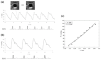
specifically, the cross section and the longitudinal section of the blood vessel are respectively measured by the geometric measurement module 100, and the pulsation animation of the cross section of the blood vessel and the thickness of the intravascular medium membrane are obtained. As one embodiment, an ultrasound imaging system is employed. As shown in fig. 2a, the ultrasound probe is gently placed on the skin surface along the minor axis of the carotid artery to avoid squeezing the blood vessel. The inclination angle of the ultrasonic probe is adjusted to ensure that the imaging surface of the probe is vertical to the local blood vessel, and the cross section of the blood vessel is kept in the middle of the imaging surface as much as possible. An ultrasound image 5s is recorded, corresponding to about 5-7 cardiac cycles, corresponding frame by frame images denoted F1, F2, …, Fn, as shown in fig. 2 b. While recording the ultrasound images, an electrocardiogram signal ECG (electrocardiogram) is recorded at the same time.
Specifically, the probe is rotated 90 ° about the midpoint of the probe, so that the vessel appears to be a cut-plane view along the longitudinal axis under ultrasound, and the position of the probe is slightly adjusted, so that the intima-media of the vessel wall is clearly imaged, as shown in fig. 2 c. The ultrasound image 5s is recorded for about 5-7 cardiac cycles, corresponding frame by frame images denoted Fl1, Fl2, …, Fln, as shown in fig. 2 d.
Specifically, the carotid blood pressure is measured with the pressure measurement module 200, and as an example, with a pressure sensor, as shown in FIG. 3 a. The method for measuring blood pressure used in this embodiment is a flattening method, as shown in fig. 3b, the pressure sensor is pressed against the carotid artery, so that the carotid artery is tightly attached to the bone below, the artery is in a flattened shape, and the pressure signal output by the pressure sensor is recorded. (it should be emphasized that the pressure waveform obtained by the sensor is only the relative value of the carotid blood pressure, and calibration is needed to obtain the absolute value of the pressure.) the brachial artery systolic pressure and diastolic pressure are measured by an electronic sphygmomanometer, and the carotid artery pressure is calibrated by the brachial artery pressure value, and the specific calibration method will be described in the next section. The pressure waveform was recorded for 5s, corresponding to about 5-7 cardiac cycles. While recording the pressure signal, an electrocardiogram signal ECG is recorded at the same time.
Specifically, the image of the cross section of the blood vessel obtained by the geometric measurement module 100 measures the luminal area of the blood vessel frame by frame, and the area or the equivalent radius may be analyzed as experimental data. The cross-sectional area may be the area enclosed by the vessel boundary, or may be the area obtained when fitting a circle, ellipse or other shape. As an embodiment, the cross-sectional area is fitted with a circle, the area is marked as A, and the radius r of the blood vessel is obtained by calculating the areaiThe measured waveform is shown in FIG. 5aAs shown.
Specifically, the intima-media thickness (IMT) of the blood vessel is measured from the image of the longitudinal section of the blood vessel obtained by the geometry measuring module 100. As an example, when measuring intima-media thickness using ultrasound, the intima-media thickness h (which corresponds to the maximum value of intima-media thickness and the vessel diameter reaches the minimum value) is recorded during diastole due to the limitation of the resolution of the ultrasound image, as shown in FIG. 4 b.
Specifically, if the blood vessel pressure is obtained by an indirect measurement method, the real blood pressure needs to be obtained by calibration. As an example, a skin surface pressure waveform generated by blood vessel pulsation is obtained by a pressure sensor and calibrated by combining a brachial artery pressure value obtained by an electronic sphygmomanometer. The calibration principle is to consider that the diastolic pressure and the average pressure of the brachial artery and the carotid artery are equal, so that the absolute pressure value P of the carotid artery can be obtained, and the measurement result is shown in FIG. 5 b.
The pressure-radius relationship is obtained by time-aligning the radius curve (fig. 5a) and the pressure curve (fig. 5b) by means of an electrocardiogram, as shown in fig. 5 c. It is emphasized that the pressure and radius data for the entire time period, as well as the loading segment (i.e., the portion of the curve where both pressure and radius are in the ascending segment), can be extracted as raw data to fit the vessel-hardening parameters.
The fitting method of the vascular sclerosis parameters comprises the following steps: the vascular mechanical properties are described by a specific constitutive model. As an example, the HGO constitutive model:
wherein the meaning of each variable is: w represents the strain energy density function, μ represents the shear modulus of the elastic fibers, c represents the shear modulus of the collagen fibers, b
θRepresenting the hardening coefficient of the vessel in the circumferential direction, b
zRepresents the hardening coefficient of the blood vessel along the axial direction, and lambda is the circumferential extension ratio
zAs axial elongation ratio, I
1=λ
2+λ
z 2+λ
-2λ
z -2。
Establishing a mechanical model of the internal pressure of the thick-wall cylinder, and obtaining a pressure-radius (P-r) relation through theoretical analysis, for example, using the results of the HGO structure:
wherein the meaning of each variable is: λ is the hoop elongation ratio, λ R/R, where R represents the radius at any material point in the initial configuration and R represents the radius at the corresponding material point in the current configuration, as shown in fig. 6. LambdazAs axial elongation ratio, λzZ/Z, which represents the ratio of the axial length of the blood vessel in the current configuration to the axial length in the initial configuration. LambdaiIs the elongation ratio at the inner diameter, λi=ri/RiWherein R isiCorresponding to the inner diameter of the vessel in the initial configuration, riCorresponding to the inner diameter of the vessel in the current configuration, as shown in fig. 6. Lambda [ alpha ]oIs defined as lambdao=ro/RoWherein R iso=Ri+H,ro=ri+ H, H and H correspond to vessel wall thickness for the initial and current configurations, respectively. P represents pressure, μ represents shear modulus of elastic fiber, c represents shear modulus of collagen fiber, bθRepresenting the hardening coefficient of the vessel in the circumferential direction, bzIndicating the hardening coefficient of the blood vessel in the axial direction.
In addition, the geometric relationship between the initial configuration and the current configuration is obtained by the mechanical principle:
wherein the meaning of each variable is: h and H correspond to vessel wall thickness, R, of the initial and current configurations, respectivelyiAnd riThe inner diameters, lambda, of the vessels corresponding to the initial configuration and the current configuration, respectivelyzIs the axial elongation ratio.
And fitting the measurement result by using a theoretical curve to obtain a parameter set omega and obtain vascular sclerosis parameters. As the details of the implementation of this step, the experimental data is (r)j,Pj) J-1, 2,3, …, n, n denotes the total number of experimental data points, and the blood vesselAnd (5) the wall thickness h. The parameter r is the inner diameter r of blood vesseli. A parameter set is defined as (μ, c, b)θ,bz,λz,Ri) The unknown parameter H passes through the formula (3) and experimental data H and riParameter set parameter Ri、λzAnd (6) performing calculation. Using theoretical curve (2) formula to test data (r)j,Pj) Fitting is carried out to obtain a parameter set omega, and a parameter b is extracted from omegaθAs a vascular sclerosis parameter.
And repeatedly acquiring the parameter set omega by changing the initial guess value, and checking the stability of the hardening parameters. Taking HGO constitutive model as an example, different initial guess values, hardening parameters b are takenθThe inversion stability of (2) is high, and the error is only within +/-10%.
Thus, a stable vascular sclerosis parameter b can be obtainedθThe expressed mechanical meaning is the hardening index of the blood vessel along the annular direction, and the value can be used as a direct parameter for representing the hardening of the blood vessel. The material parameter has the characteristics of good stability and clear mechanical meaning, so the material has better clinical application value and is expected to become a new index for clinically diagnosing the rigidity of the blood vessel.
Therefore, the method and the device can measure the hardening parameters of the blood vessels, have the characteristics of simplicity in operation and stable data, and comprise a geometric measurement module, a pressure measurement module, a data processing module and a display output module. The geometric measurement module is responsible for acquiring a geometric variation waveform of the superficial artery in a cardiac cycle; the pressure measurement module is responsible for acquiring a pressure change waveform of the superficial artery in a cardiac cycle; the data processing module is responsible for extracting and analyzing the image and pressure data and consists of a computer and software loaded on the computer; the display output module is composed of a computer and is responsible for outputting the hardening parameters of the blood vessels in a screen display mode.
The device for measuring the vascular sclerosis parameter has the advantages of good feasibility, simple measuring method and low measuring equipment cost, the cost is far lower than that of a shear wave elastography-based method, the vascular sclerosis parameter is measured, the stable material sclerosis parameter is obtained, the intrinsic mechanical property of the blood vessel is reflected, the device has potential application value in detecting diseases such as arteriosclerosis and the like, the device is expected to become a new clinical index, the real-time performance is good, the data processing speed is high, and the vascular sclerosis parameter can be obtained in real time.
The device for measuring the vascular sclerosis parameter of the embodiment of the application is used for acquiring a cross-section image and a longitudinal-section image of a blood vessel through imaging equipment through a geometric measurement module; the pressure measurement module is used for acquiring a pressure signal of a blood vessel through a sensor; the data processing module is used for analyzing the blood vessel cross section image and the blood vessel longitudinal section image, acquiring a geometric change waveform, analyzing the pressure signal, acquiring a pressure change waveform, and processing according to the geometric change waveform and the pressure change waveform to acquire a blood vessel hardening parameter; and the display output module is used for displaying the vascular sclerosis parameters. Therefore, stable angiosclerosis parameters can be obtained, and the method has a good clinical application value.
In order to realize the embodiment, the application also provides a method for measuring the vascular sclerosis parameter.
Fig. 7 is a schematic flowchart of a method for measuring vascular sclerosis parameters according to an embodiment of the present disclosure.
As shown in fig. 7, the method for measuring vascular sclerosis parameters comprises the following steps:
step 101, obtaining a cross-section image and a longitudinal-section image of a blood vessel by an imaging device.
Step 102, acquiring a pressure signal of a blood vessel through a sensor.
And 103, analyzing the blood vessel cross-section image and the blood vessel longitudinal-section image to obtain a geometric variation waveform, analyzing the pressure signal to obtain a pressure variation waveform, and processing according to the geometric variation waveform and the pressure variation waveform to obtain a blood vessel hardening parameter.
And 104, displaying the vascular sclerosis parameters.
According to the method for measuring the vascular sclerosis parameters, the cross-section image and the longitudinal-section image of the blood vessel are obtained through the imaging equipment; acquiring a pressure signal of a blood vessel through a sensor; analyzing the cross section image and the longitudinal section image of the blood vessel to obtain a geometric variation waveform, analyzing the pressure signal to obtain a pressure variation waveform, and processing according to the geometric variation waveform and the pressure variation waveform to obtain a vascular sclerosis parameter; vascular sclerosis parameters are displayed. Therefore, stable angiosclerosis parameters can be obtained, and the method has a good clinical application value.
It should be noted that the foregoing explanation of the embodiment of the apparatus for measuring vascular sclerosis also applies to the method for measuring vascular sclerosis of the embodiment, and is not repeated herein.
In the description herein, reference to the description of the term "one embodiment," "some embodiments," "an example," "a specific example," or "some examples," etc., means that a particular feature, structure, material, or characteristic described in connection with the embodiment or example is included in at least one embodiment or example of the application. In this specification, the schematic representations of the terms used above are not necessarily intended to refer to the same embodiment or example. Furthermore, the particular features, structures, materials, or characteristics described may be combined in any suitable manner in any one or more embodiments or examples. Furthermore, various embodiments or examples and features of different embodiments or examples described in this specification can be combined and combined by one skilled in the art without contradiction.
Furthermore, the terms "first", "second" and "first" are used for descriptive purposes only and are not to be construed as indicating or implying relative importance or implicitly indicating the number of technical features indicated. Thus, a feature defined as "first" or "second" may explicitly or implicitly include at least one such feature. In the description of the present application, "plurality" means at least two, e.g., two, three, etc., unless explicitly specified otherwise.
Any process or method descriptions in flow charts or otherwise described herein may be understood as representing modules, segments, or portions of code which include one or more executable instructions for implementing steps of a custom logic function or process, and alternate implementations are included within the scope of the preferred embodiment of the present application in which functions may be executed out of order from that shown or discussed, including substantially concurrently or in reverse order, depending on the functionality involved, as would be understood by those reasonably skilled in the art of the present application.
The logic and/or steps represented in the flowcharts or otherwise described herein, e.g., an ordered listing of executable instructions that can be considered to implement logical functions, can be embodied in any computer-readable medium for use by or in connection with an instruction execution system, apparatus, or device, such as a computer-based system, processor-containing system, or other system that can fetch the instructions from the instruction execution system, apparatus, or device and execute the instructions. For the purposes of this description, a "computer-readable medium" can be any means that can contain, store, communicate, propagate, or transport the program for use by or in connection with the instruction execution system, apparatus, or device. More specific examples (a non-exhaustive list) of the computer-readable medium would include the following: an electrical connection (electronic device) having one or more wires, a portable computer diskette (magnetic device), a Random Access Memory (RAM), a read-only memory (ROM), an erasable programmable read-only memory (EPROM or flash memory), an optical fiber device, and a portable compact disc read-only memory (CDROM). Additionally, the computer-readable medium could even be paper or another suitable medium upon which the program is printed, as the program can be electronically captured, via for instance optical scanning of the paper or other medium, then compiled, interpreted or otherwise processed in a suitable manner if necessary, and then stored in a computer memory.
It should be understood that portions of the present application may be implemented in hardware, software, firmware, or a combination thereof. In the above embodiments, the various steps or methods may be implemented in software or firmware stored in memory and executed by a suitable instruction execution system. If implemented in hardware, as in another embodiment, any one or combination of the following techniques, which are known in the art, may be used: a discrete logic circuit having a logic gate circuit for implementing a logic function on a data signal, an application specific integrated circuit having an appropriate combinational logic gate circuit, a Programmable Gate Array (PGA), a Field Programmable Gate Array (FPGA), or the like.
It will be understood by those skilled in the art that all or part of the steps carried by the method for implementing the above embodiments may be implemented by hardware related to instructions of a program, which may be stored in a computer readable storage medium, and when the program is executed, the program includes one or a combination of the steps of the method embodiments.
In addition, functional units in the embodiments of the present application may be integrated into one processing module, or each unit may exist alone physically, or two or more units are integrated into one module. The integrated module can be realized in a hardware mode, and can also be realized in a software functional module mode. The integrated module, if implemented in the form of a software functional module and sold or used as a separate product, may also be stored in a computer-readable storage medium.
The storage medium mentioned above may be a read-only memory, a magnetic or optical disk, etc. Although embodiments of the present application have been shown and described above, it is understood that the above embodiments are exemplary and should not be construed as limiting the present application, and that variations, modifications, substitutions and alterations may be made to the above embodiments by those of ordinary skill in the art within the scope of the present application.