Disclosure of Invention
The embodiment of the disclosure provides a metal middle frame, a millimeter wave antenna structure and a mobile terminal, which can solve the problem that a millimeter wave module can only cover in a single direction but cannot cover in multiple directions. The technical scheme is as follows:
according to an aspect of the present disclosure, there is provided a metal middle frame, a frame body of which includes: a first side and a second side joined at their sides;
the frame body is provided with an L-shaped slot, the L-shaped slot comprises a first slot edge and a second slot edge, the end points of the first slot edge and the second slot edge are connected, the first slot edge is arranged on the first side face, and the second slot edge is arranged on the second side face;
the millimeter wave antenna is arranged in the L-shaped slot and used for millimeter wave radiation through the first slot edge and the second slot edge of the L-shaped slot.
In an optional embodiment, the frame body is provided with n L-shaped slots, where the n L-shaped slots are arranged in an array on the frame body, and n is a positive integer.
In an optional embodiment, the n L-shaped slots include n end-to-end first slot edges and n end-to-end second slot edges;
the n first slot edges are arranged on the first side face in parallel, and the n second slot edges are arranged on the second side face in parallel.
In an optional embodiment, the frame body of the metal middle frame further includes: a third side joined to said first side and said second side;
n L-shaped slot seams are arranged on the frame body, and n is a positive integer;
p L type slot seam set up in the first side with the junction of second side, q L type slot seam set up in the second side with the junction of third side, k L type slot seam set up in the first side with the junction of third side, wherein, p, q, k all are positive integers, and p, q, k sum is n.
In an optional embodiment, the frame body of the metal middle frame further comprises a fourth side surface connected with the second side surface and not connected with the first side surface;
n L-shaped slot seams are arranged on the frame body, and n is a positive integer;
f L type slot sets up in the first side with the junction of second side, g L type slot sets up in the second side with the junction of fourth side, wherein, f, g all are positive integer, and f, g sum are n.
In an optional embodiment, a metal strip is arranged in the metal middle frame and at a position separated from the L-shaped slot by a preset distance, and the metal strip is perpendicular to the first slot edge and the second slot edge in the L-shaped slot;
the millimeter wave antenna is coupled and fed through the metal strip.
In an optional embodiment, a feeding point is welded on the L-shaped slot, and the feeding point is used for feeding the millimeter wave antenna.
In an optional embodiment, an electrical connection metal sheet is connected to the L-shaped slot, and the millimeter wave antenna is fed by hard contact with the electrical connection metal sheet.
In an alternative embodiment, the L-shaped slot is a slot filled with an insulating material;
or the like, or, alternatively,
the L-shaped slot is a hollow slot;
or the like, or, alternatively,
the L-shaped slot is a slot covered by a net structure.
According to another aspect of the present disclosure, there is provided a millimeter-wave antenna structure including: metal center and millimeter wave antenna, the metal center includes the metal center that this disclosed embodiment provided as described above.
According to another aspect of the present disclosure, there is provided a mobile terminal including: metal center and millimeter wave antenna, the metal center includes the metal center that this disclosed embodiment provided as described above.
The technical scheme provided by the embodiment of the disclosure has the beneficial effects that:
through set up L type slot joint between first side and second side to through the first slot joint limit and the second slot joint limit radiation millimeter wave of this L type slot joint, promptly, single millimeter wave module can carry out millimeter wave radiation in the direction that first side corresponds and the direction that the second side corresponds, and single millimeter wave module covers two directions simultaneously, has widened the coverage of millimeter wave antenna, strengthens millimeter wave radiation's performance.
Detailed Description
Reference will now be made in detail to the exemplary embodiments, examples of which are illustrated in the accompanying drawings. When the following description refers to the accompanying drawings, like numbers in different drawings represent the same or similar elements unless otherwise indicated. The implementations described in the exemplary embodiments below are not intended to represent all implementations consistent with the present disclosure. Rather, they are merely examples of apparatus and methods consistent with certain aspects of the present disclosure, as detailed in the appended claims.
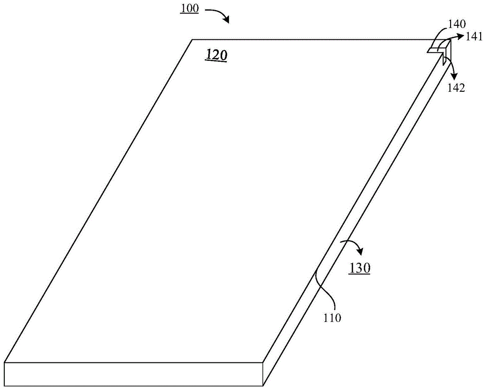
Fig. 1 is a schematic view of a metal middle frame 100 provided in an exemplary embodiment of the present disclosure, where the metal middle frame 100 is used to provide a millimeter wave antenna, and as shown in fig. 1, a frame body of the metal middle frame 100 includes: a first side 120 and a second side 130 joined by a side 110;
the metal middle frame 100 is provided with an L-shaped slot 140, the L-shaped slot 140 includes a first slot edge 141 and a second slot edge 142, where the end points of the first slot edge 141 and the second slot edge 142 are connected, the first slot edge 141 is disposed on the first side surface 120, and the second slot edge 142 is disposed on the second side surface 130.
Alternatively, the first side 120 and the second side 130 are illustrated in fig. 1 as being connected by the longitudinal side 110, the first side 120 and the second side 130 can also be connected by the transverse side, which is not limited in the embodiments of the present disclosure, and as can be seen from the terminal structure, in the terminal frame generally includes 8 sides, the first side 120 and the second side 130 can be two sides connected by any one of the 8 sides.
Optionally, when the first side 120 and the second side 130 are joined by longitudinal sides, the first slot edge 141 and the second slot edge 142 of the L-shaped slot 140 are perpendicular to the longitudinal sides, and the first slot edge 141 is parallel to the terminal transverse side on the first side 120 and the second slot edge 142 is parallel to the terminal transverse side on the second side 130; when the first side 120 and the second side 130 are joined by lateral sides, the first slot edge 141 and the second slot edge 142 of the L-shaped slot 140 are perpendicular to the lateral sides, with the first slot edge 141 being parallel to the terminal longitudinal side on the first side 120 and the second slot edge 142 being parallel to the terminal longitudinal side on the second side 130.
Optionally, the first slot edge 141 of the L-shaped slot 140 may be disposed at any angle on the first side 120, and the second slot edge 142 may be disposed at any angle on the second side 130, which is not limited by the embodiment of the disclosure.
Optionally, the L-shaped slot 140 is a slot filled with an insulating material, such as: glass, plastic, etc., or the L-shaped slot 140 is a hollow slot; alternatively, the L-shaped slot 140 is a slot covered by a net structure, such as: when the L-shaped slot 140 is located at the position of the microphone, the receiver, and the loudspeaker, the L-shaped slot 140 is covered by a net structure.
Optionally, the millimeter-wave antenna at the L-shaped slot 140 needs to be fed, and the feeding manner of the millimeter-wave antenna includes at least one of the following manners:
firstly, a metal strip is arranged at a position in the metal middle frame 100, which is separated from the L-shaped slot 140 by a preset distance, the metal strip is perpendicular to a first slot edge and a second slot edge in the L-shaped operation, and the millimeter wave antenna is fed by the metal strip in a coupling manner;
referring to fig. 2, schematically, a metal strip 210 is disposed at a position of the L-shaped slot 140 at a predetermined distance, the metal strip 210 is perpendicular to the L-shaped slot, and the millimeter-wave antenna corresponding to the L-shaped slot 140 is fed by the metal strip 210.
Secondly, a feed point is welded on the L-shaped slot, and the millimeter wave antenna is fed through the feed point;
thirdly, an electric connection metal sheet is connected to the L-shaped slot, and the millimeter wave antenna feeds power through hard contact with the electric connection metal sheet.
Optionally, the electrically connecting metal sheet may be implemented in a form of a spring sheet, and may also be implemented in other forms, which are not limited in this disclosure.
Optionally, the millimeter wave antenna may be disposed at the L-shaped slot by using a Laser Direct Structuring (LDS) technique, or may be disposed at the L-shaped slot by using a flexible board, such as: liquid Crystal Polymer film (LCP), Flexible Printed Circuit (FPC), Modified Polyimide (MPI), and the like.
To sum up, the metal middle frame that this disclosed embodiment provided through set up L type slot between first side and second side to through the first slot seam limit and the second slot limit radiation millimeter wave of this L type slot, promptly, single millimeter wave module can carry out millimeter wave radiation in the direction that first side corresponds and the direction that the second side corresponds, and single millimeter wave module covers two directions simultaneously, has widened the coverage of millimeter wave antenna, strengthens millimeter wave radiation's performance.
In an optional embodiment, a plurality of L-shaped slots may be further disposed on the metal middle frame 100, and illustratively, n L-shaped slots are disposed on the metal middle frame 100, where n is a positive integer, and the n L-shaped slots may be disposed between the same two side surfaces and arranged in an array, or disposed between different side surfaces, which is not limited in the embodiment of the present disclosure.
Illustratively, the arrangement of the n L-shaped slots includes any one of the following ways:
firstly, n L-shaped slots are arranged on a frame body in an array mode;
optionally, the n L-shaped slots include n first slot edges and n second slot edges connected at end points, the n first slot edges are arranged in parallel on the first side surface, and the n second slot edges are arranged in parallel on the second side surface.
Referring to fig. 3, a schematic diagram of an array arrangement of L-shaped slots provided in an exemplary embodiment of the present disclosure is shown, and it is described by taking 4L-shaped slots as an example, as shown in fig. 3, an L-shaped slot 310, an L-shaped slot 320, an L-shaped slot 330, and an L-shaped slot 340 are provided on a frame body of the metal middle frame 100;
the L-shaped slot 310 includes a first slot edge 311 and a second slot edge 312, the end points of which are connected, the first slot edge 311 is disposed on the first side 350, the second slot edge 312 is disposed on the second side 360, and optionally, a millimeter wave antenna is disposed in the L-shaped slot 310, and the millimeter wave antenna is configured to perform millimeter wave radiation through the first slot edge 311 and the second slot edge 312 of the L-shaped slot 310;
the L-shaped slot 320 includes a first slot edge 321 and a second slot edge 322 with end points connected, the first slot edge 321 is disposed on the first side 350, the second slot edge 322 is disposed on the second side 360, and optionally, a millimeter wave antenna is disposed in the L-shaped slot 320, and the millimeter wave antenna is configured to perform millimeter wave radiation through the first slot edge 321 and the second slot edge 322 of the L-shaped slot 320;
the L-shaped slot 330 includes a first slot edge 331 and a second slot edge 332 with end points connected, the first slot edge 331 is disposed on the first side 350, the second slot edge 332 is disposed on the second side 360, and optionally, a millimeter wave antenna is disposed in the L-shaped slot 330, and the millimeter wave antenna is configured to perform millimeter wave radiation through the first slot edge 331 and the second slot edge 332 of the L-shaped slot 330;
the L-shaped slot 340 includes a first slot seam 341 and a second slot seam 342, the end points of which are connected, the first slot seam 341 is disposed on the first side 350, the second slot seam 342 is disposed on the second side 360, and optionally, a millimeter wave antenna is disposed in the L-shaped slot 340, and the millimeter wave antenna is used for millimeter wave radiation through the first slot seam 341 and the second slot seam 342 of the L-shaped slot 340;
alternatively, the first slot edge 311, the first slot edge 321, the first slot edge 331, and the first slot edge 341 are arranged in parallel on the first side 350, and the second slot edge 312, the second slot edge 322, the second slot edge 332, and the second slot edge 342 are arranged in parallel on the second side 360, that is, the L-shaped slots 310, the L-shaped slots 320, the L-shaped slots 330, and the L-shaped slots 340 are arranged in an array between the first side 350 and the second side 360.
Optionally, the n L-shaped slots may respectively correspond to one radio frequency front end, or a plurality of L-shaped slots may correspond to one radio frequency front end and be controlled by a switch.
Second, n L-shaped slots are distributed on the frame body between the first side surface and the second side surface and between the second side surface and the third side surface
Between the faces and between the first side and the third side;
optionally, the frame body of the metal middle frame 100 further includes a third side surface connected to the first side surface and the second side surface, p L-shaped slots are disposed at a connection position of the first side surface and the second side surface, q L-shaped slots are disposed at a connection position of the second side surface and the third side surface, and k L-shaped slots are disposed at a connection position of the first side surface and the third side surface, where p, q, and k are positive integers, and a sum of p, q, and k is n. Optionally, one or two of p, q, and k may be 0.
Schematically, as shown in fig. 4, a schematic diagram of an L-shaped slot arrangement provided by an exemplary embodiment of the present disclosure is shown, and it is described by taking 4L-shaped slots as an example, as shown in fig. 4, an L-shaped slot 410, an L-shaped slot 420, an L-shaped slot 430, and an L-shaped slot 440 are provided on a frame body of the metal middle frame 100;
the L-shaped slot 410 includes a first slot margin 411 and a second slot margin 412, which are connected at end points, the first slot margin 411 is disposed on the first side surface 450, the second slot margin 412 is disposed on the second side surface 460, and optionally, a millimeter wave antenna is disposed in the L-shaped slot 410, and the millimeter wave antenna is configured to perform millimeter wave radiation through the first slot margin 411 and the second slot margin 412 of the L-shaped slot 410;
the L-shaped slot 420 includes a first slot edge 421 and a second slot edge 422, end points of which are connected, the first slot edge 421 is disposed on the first side surface 450, the second slot edge 422 is disposed on the second side surface 460, and optionally, a millimeter wave antenna is disposed in the L-shaped slot 420, and the millimeter wave antenna is configured to perform millimeter wave radiation through the first slot edge 421 and the second slot edge 422 of the L-shaped slot 420;
the L-shaped slot 430 comprises a first slot edge 431 and a second slot edge 432, the end points of which are connected, the first slot edge 431 is arranged on the second side surface 460, the second slot edge 432 is arranged on the third side surface 470, and optionally, a millimeter wave antenna is arranged in the L-shaped slot 430, and is used for millimeter wave radiation through the first slot edge 431 and the second slot edge 432 of the L-shaped slot 430;
the L-shaped slot 440 includes a first slot edge 441 and a second slot edge 442, which are end-to-end, the first slot edge 441 is disposed on the first side 450, the second slot edge 442 is disposed on the third side 470, and optionally, a millimeter wave antenna is disposed in the L-shaped slot 440, and the millimeter wave antenna is configured to radiate millimeter waves through the first slot edge 441 and the second slot edge 442 of the L-shaped slot 440.
In summary, the metal middle frame provided by this embodiment, the L-shaped slot is disposed between the first side surface and the second side surface, between the second side surface and the third side surface, and the first slot edge and the second slot edge of the L-shaped slot radiate the millimeter waves, that is, the millimeter wave module can radiate the millimeter waves in the direction corresponding to the first side surface, the direction corresponding to the second side surface, and the direction corresponding to the third side surface, and cover three directions at the same time, so that the coverage range of the millimeter wave antenna is expanded, and the performance of the millimeter wave radiation is enhanced.
Third, n L-shaped slots are distributed on the frame body between the first side surface and the second side surface and between the second side surface and the fourth side surface
Between the faces;
optionally, the frame body of the metal middle frame 100 further includes a fourth side surface connected to the second side surface and disconnected from the first side surface, f L-shaped slots are disposed at a connection position of the first side surface and the second side surface, and g L-shaped slots are disposed at a connection position of the second side surface and the fourth side surface, where f and g are positive integers, and a sum of f and g is n. Optionally, one of f and g may have a value of 0.
Schematically, as shown in fig. 5, a schematic diagram of an L-shaped slot arrangement provided in an exemplary embodiment of the present disclosure is shown, and the frame body is described as including 3L-shaped slots, as shown in fig. 5, the frame body of the metal middle frame 100 is provided with an L-shaped slot 510, an L-shaped slot 520, and an L-shaped slot 530;
the L-shaped slot 510 includes a first slot edge 511 and a second slot edge 512, the end points of which are connected, the first slot edge 511 is disposed on the first side surface 550, the second slot edge 512 is disposed on the second side surface 560, and optionally, a millimeter wave antenna is disposed in the L-shaped slot 510, and the millimeter wave antenna is configured to radiate millimeter waves through the first slot edge 511 and the second slot edge 512 of the L-shaped slot 510;
the L-shaped slot 520 comprises a first slot edge 521 and a second slot edge 522 which are connected in end points, the first slot edge 521 is arranged on the first side surface 550, the second slot edge 522 is arranged on the second side surface 560, and optionally, a millimeter wave antenna is arranged in the L-shaped slot 520 and is used for millimeter wave radiation through the first slot edge 521 and the second slot edge 522 of the L-shaped slot 520;
the L-shaped slot 530 includes a first slot margin 531 and a second slot margin 532 having end points joined, the first slot margin 531 is disposed on the second side 560, the second slot margin 532 is disposed on the fourth side 570, and optionally a millimeter wave antenna is disposed within the L-shaped slot 530 for millimeter wave radiation through the first slot margin 531 and the second slot margin 532 of the L-shaped slot 530.
Referring to fig. 6, schematically, an S-11 parameter diagram provided by an exemplary embodiment of the present disclosure is shown, as shown in fig. 6, after the L-shaped slot is arranged in the above manner, the millimeter wave antenna of the terminal reaches-14.193 dB when the frequency reaches 28GHz, which meets the radio frequency requirement of millimeter waves.
Fig. 7 is a block diagram of a mobile terminal according to an exemplary embodiment of the present disclosure, and as shown in fig. 7, the mobile terminal 700 includes: a metal bezel 710 and a millimeter wave antenna 720.
The mobile terminal 700 is a terminal capable of positioning, and optionally, the mobile terminal may be any one of a mobile phone, a tablet, a laptop computer, and a car navigator.
The metal middle frame 710 is the metal middle frame described in any one of fig. 1 to 3, the millimeter wave antenna 720 is configured to radiate millimeter waves, and the millimeter wave antenna 720 is disposed on the metal middle frame 710. Optionally, the terminal 700 further includes:
a memory storing at least one instruction, at least one piece of code, a code level, or a set of instructions to be loaded by the processor and to perform a function to be performed by the mobile terminal 700.
The processor is configured to load the at least one instruction, the at least one section of code, the code set, or the instruction set stored in the memory, so as to execute a function to be implemented by the mobile terminal 700, and optionally, the processor may be at least one of a single-core processor, a multi-core processor, and an embedded chip.
FIG. 8 is a block diagram illustrating a computer device 800 according to an example embodiment. The computer device 800 may be, for example, the terminal introduced above. For example, the terminal may be an electronic device such as a mobile phone, a tablet Computer, an e-book reader, a multimedia playing device, a Personal Computer (PC), and a wearable device.
Referring to fig. 8, computer device 800 may include one or more of the following components: processing component 802, memory 804, power component 806, multimedia component 808, audio component 810, Input/Output (I/O) interface 812, sensor component 814, and communication component 816.
The processing component 802 generally controls overall operation of the computer device 800, such as operations associated with display, telephone calls, data communications, camera operations, and recording operations. The processing components 802 may include one or more processors 820 to execute instructions. Further, the processing component 802 can include one or more modules that facilitate interaction between the processing component 802 and other components. For example, the processing component 802 can include a multimedia module to facilitate interaction between the multimedia component 808 and the processing component 802.
The memory 804 is configured to store various types of data to support operations at the computer device 800. Examples of such data include instructions for any application or method operating on computer device 800, contact data, phonebook data, messages, pictures, videos, and so forth. The Memory 804 may be implemented by any type of volatile or non-volatile Memory device or combination thereof, such as Static Random-Access Memory (SRAM), Electrically Erasable Programmable Read Only Memory (EEPROM), Erasable Programmable Read Only Memory (EPROM), Programmable Read Only Memory (PROM), Read Only Memory (ROM), magnetic Memory, flash Memory, magnetic disk or optical disk.
The power components 806 provide power to the various components of the computer device 800. The power components 806 may include a power management system, one or more power supplies, and other components associated with generating, managing, and distributing power for the computer device 800.
The multimedia component 808 includes a screen that provides an output interface between the computer device 800 and a user. In some embodiments, the screen may include an Organic Light-Emitting Diode (OLED) display screen and a Touch Panel (TP). If the screen includes a touch panel, the screen may be implemented as a touch screen to receive an input signal from a user. The touch panel includes one or more touch sensors to sense touch, slide, and gestures on the touch panel. The touch sensor may not only sense the boundary of a touch or slide action, but also detect the duration and pressure associated with the touch or slide operation. In some embodiments, the multimedia component 808 includes a front facing camera and/or a rear facing camera. The front-facing camera and/or the rear-facing camera may receive external multimedia data when the computer device 800 is in an operating mode, such as a shooting mode or a video mode. Each front camera and rear camera may be a fixed optical lens system or have a focal length and optical zoom capability.
The audio component 810 is configured to output and/or input audio signals. For example, audio component 810 includes a Microphone (MIC) configured to receive external audio signals when computer device 800 is in an operational mode, such as a call mode, a recording mode, and a voice recognition mode. The received audio signals may further be stored in the memory 804 or transmitted via the communication component 816. In some embodiments, audio component 810 also includes a speaker for outputting audio signals.
The I/O interface 812 provides an interface between the processing component 802 and peripheral interface modules, which may be keyboards, click wheels, buttons, etc. These buttons may include, but are not limited to: a home button, a volume button, a start button, and a lock button.
The sensor assembly 814 includes one or more sensors for providing various aspects of state assessment for the computer device 800. For example, the sensor assembly 814 can detect an open/closed state of the computer device 800, the relative positioning of components, such as a display and keypad of the computer device 800, the sensor assembly 814 can also detect a change in position of the computer device 800 or a component of the computer device 800, the presence or absence of user contact with the computer device 800, orientation or acceleration/deceleration of the computer device 800, and a change in temperature of the computer device 800. Sensor assembly 814 may include a proximity sensor configured to detect the presence of a nearby object without any physical contact. The sensor assembly 814 may also include a photosensor, such as a Complementary Metal Oxide Semiconductor (CMOS) or Charge-coupled Device (CCD) image sensor, for use in imaging applications. In some embodiments, the sensor assembly 814 may also include an acceleration sensor, a gyroscope sensor, a magnetic sensor, a pressure sensor, or a temperature sensor.
The communication component 816 is configured to facilitate communications between the computer device 800 and other devices in a wired or wireless manner. The computer device 800 may access a wireless network based on a communication standard, such as Wi-Fi, 2G, or 3G, or a combination thereof. In an exemplary embodiment, the communication component 816 receives a broadcast signal or broadcast related information from an external broadcast management system via a broadcast channel. In an exemplary embodiment, the Communication component 816 further includes a Near Field Communication (NFC) module to facilitate short-range communications. For example, the NFC module may be implemented based on Radio Frequency Identification (RFID) technology, Infrared Data Association (IrDA) technology, Ultra Wide Band (UWB) technology, BlueTooth (BlueTooth, BT) technology, and other technologies.
In an exemplary embodiment, the computer Device 800 may be implemented by one or more Application Specific Integrated Circuits (ASICs), Digital Signal Processors (DSPs), Digital Signal Processing Devices (DSPDs), Programmable Logic Devices (PLDs), Field Programmable Gate Arrays (FPGAs), controllers, microcontrollers, microprocessors, or other electronic components.
In an exemplary embodiment, a non-transitory computer readable storage medium is also provided, having stored thereon a computer program that, when executed by a processor of the computer device 800, enables the computer device 800 to implement controlling a millimeter wave antenna. For example, the non-transitory computer-readable storage medium may be a ROM, a Random-Access Memory (RAM), a CD-ROM, a magnetic tape, a floppy disk, an optical data storage device, and the like.
Other embodiments of the disclosure will be apparent to those skilled in the art from consideration of the specification and practice of the disclosure disclosed herein. This disclosure is intended to cover any variations, uses, or adaptations of the disclosure following, in general, the principles of the disclosure and including such departures from the present disclosure as come within known or customary practice within the art to which the disclosure pertains. It is intended that the specification and examples be considered as exemplary only, with a true scope and spirit of the disclosure being indicated by the following claims.
It will be understood that the present disclosure is not limited to the precise arrangements described above and shown in the drawings and that various modifications and changes may be made without departing from the scope thereof. The scope of the present disclosure is limited only by the appended claims.