CN112740024A - Particle isolation from whole blood - Google Patents
Particle isolation from whole blood Download PDFInfo
- Publication number
- CN112740024A CN112740024A CN201880097962.XA CN201880097962A CN112740024A CN 112740024 A CN112740024 A CN 112740024A CN 201880097962 A CN201880097962 A CN 201880097962A CN 112740024 A CN112740024 A CN 112740024A
- Authority
- CN
- China
- Prior art keywords
- buffer
- particle separation
- whole blood
- particles
- interest
- Prior art date
- Legal status (The legal status is an assumption and is not a legal conclusion. Google has not performed a legal analysis and makes no representation as to the accuracy of the status listed.)
- Pending
Links
Images


Classifications
-
- B—PERFORMING OPERATIONS; TRANSPORTING
- B01—PHYSICAL OR CHEMICAL PROCESSES OR APPARATUS IN GENERAL
- B01L—CHEMICAL OR PHYSICAL LABORATORY APPARATUS FOR GENERAL USE
- B01L3/00—Containers or dishes for laboratory use, e.g. laboratory glassware; Droppers
- B01L3/50—Containers for the purpose of retaining a material to be analysed, e.g. test tubes
- B01L3/502—Containers for the purpose of retaining a material to be analysed, e.g. test tubes with fluid transport, e.g. in multi-compartment structures
- B01L3/5027—Containers for the purpose of retaining a material to be analysed, e.g. test tubes with fluid transport, e.g. in multi-compartment structures by integrated microfluidic structures, i.e. dimensions of channels and chambers are such that surface tension forces are important, e.g. lab-on-a-chip
- B01L3/502761—Containers for the purpose of retaining a material to be analysed, e.g. test tubes with fluid transport, e.g. in multi-compartment structures by integrated microfluidic structures, i.e. dimensions of channels and chambers are such that surface tension forces are important, e.g. lab-on-a-chip specially adapted for handling suspended solids or molecules independently from the bulk fluid flow, e.g. for trapping or sorting beads, for physically stretching molecules
-
- B—PERFORMING OPERATIONS; TRANSPORTING
- B03—SEPARATION OF SOLID MATERIALS USING LIQUIDS OR USING PNEUMATIC TABLES OR JIGS; MAGNETIC OR ELECTROSTATIC SEPARATION OF SOLID MATERIALS FROM SOLID MATERIALS OR FLUIDS; SEPARATION BY HIGH-VOLTAGE ELECTRIC FIELDS
- B03C—MAGNETIC OR ELECTROSTATIC SEPARATION OF SOLID MATERIALS FROM SOLID MATERIALS OR FLUIDS; SEPARATION BY HIGH-VOLTAGE ELECTRIC FIELDS
- B03C5/00—Separating dispersed particles from liquids by electrostatic effect
- B03C5/005—Dielectrophoresis, i.e. dielectric particles migrating towards the region of highest field strength
-
- B—PERFORMING OPERATIONS; TRANSPORTING
- B03—SEPARATION OF SOLID MATERIALS USING LIQUIDS OR USING PNEUMATIC TABLES OR JIGS; MAGNETIC OR ELECTROSTATIC SEPARATION OF SOLID MATERIALS FROM SOLID MATERIALS OR FLUIDS; SEPARATION BY HIGH-VOLTAGE ELECTRIC FIELDS
- B03C—MAGNETIC OR ELECTROSTATIC SEPARATION OF SOLID MATERIALS FROM SOLID MATERIALS OR FLUIDS; SEPARATION BY HIGH-VOLTAGE ELECTRIC FIELDS
- B03C5/00—Separating dispersed particles from liquids by electrostatic effect
- B03C5/02—Separators
- B03C5/022—Non-uniform field separators
- B03C5/026—Non-uniform field separators using open-gradient differential dielectric separation, i.e. using electrodes of special shapes for non-uniform field creation, e.g. Fluid Integrated Circuit [FIC]
-
- G—PHYSICS
- G01—MEASURING; TESTING
- G01N—INVESTIGATING OR ANALYSING MATERIALS BY DETERMINING THEIR CHEMICAL OR PHYSICAL PROPERTIES
- G01N27/00—Investigating or analysing materials by the use of electric, electrochemical, or magnetic means
- G01N27/26—Investigating or analysing materials by the use of electric, electrochemical, or magnetic means by investigating electrochemical variables; by using electrolysis or electrophoresis
- G01N27/416—Systems
- G01N27/447—Systems using electrophoresis
- G01N27/44756—Apparatus specially adapted therefor
- G01N27/44791—Microapparatus
-
- B—PERFORMING OPERATIONS; TRANSPORTING
- B01—PHYSICAL OR CHEMICAL PROCESSES OR APPARATUS IN GENERAL
- B01L—CHEMICAL OR PHYSICAL LABORATORY APPARATUS FOR GENERAL USE
- B01L2200/00—Solutions for specific problems relating to chemical or physical laboratory apparatus
- B01L2200/02—Adapting objects or devices to another
- B01L2200/026—Fluid interfacing between devices or objects, e.g. connectors, inlet details
- B01L2200/027—Fluid interfacing between devices or objects, e.g. connectors, inlet details for microfluidic devices
-
- B—PERFORMING OPERATIONS; TRANSPORTING
- B01—PHYSICAL OR CHEMICAL PROCESSES OR APPARATUS IN GENERAL
- B01L—CHEMICAL OR PHYSICAL LABORATORY APPARATUS FOR GENERAL USE
- B01L2200/00—Solutions for specific problems relating to chemical or physical laboratory apparatus
- B01L2200/06—Fluid handling related problems
- B01L2200/0636—Focussing flows, e.g. to laminate flows
-
- B—PERFORMING OPERATIONS; TRANSPORTING
- B01—PHYSICAL OR CHEMICAL PROCESSES OR APPARATUS IN GENERAL
- B01L—CHEMICAL OR PHYSICAL LABORATORY APPARATUS FOR GENERAL USE
- B01L2200/00—Solutions for specific problems relating to chemical or physical laboratory apparatus
- B01L2200/06—Fluid handling related problems
- B01L2200/0647—Handling flowable solids, e.g. microscopic beads, cells, particles
- B01L2200/0652—Sorting or classification of particles or molecules
-
- B—PERFORMING OPERATIONS; TRANSPORTING
- B01—PHYSICAL OR CHEMICAL PROCESSES OR APPARATUS IN GENERAL
- B01L—CHEMICAL OR PHYSICAL LABORATORY APPARATUS FOR GENERAL USE
- B01L2200/00—Solutions for specific problems relating to chemical or physical laboratory apparatus
- B01L2200/10—Integrating sample preparation and analysis in single entity, e.g. lab-on-a-chip concept
-
- B—PERFORMING OPERATIONS; TRANSPORTING
- B01—PHYSICAL OR CHEMICAL PROCESSES OR APPARATUS IN GENERAL
- B01L—CHEMICAL OR PHYSICAL LABORATORY APPARATUS FOR GENERAL USE
- B01L2300/00—Additional constructional details
- B01L2300/06—Auxiliary integrated devices, integrated components
- B01L2300/0627—Sensor or part of a sensor is integrated
- B01L2300/0645—Electrodes
-
- B—PERFORMING OPERATIONS; TRANSPORTING
- B01—PHYSICAL OR CHEMICAL PROCESSES OR APPARATUS IN GENERAL
- B01L—CHEMICAL OR PHYSICAL LABORATORY APPARATUS FOR GENERAL USE
- B01L2300/00—Additional constructional details
- B01L2300/08—Geometry, shape and general structure
- B01L2300/0861—Configuration of multiple channels and/or chambers in a single devices
- B01L2300/0864—Configuration of multiple channels and/or chambers in a single devices comprising only one inlet and multiple receiving wells, e.g. for separation, splitting
-
- B—PERFORMING OPERATIONS; TRANSPORTING
- B01—PHYSICAL OR CHEMICAL PROCESSES OR APPARATUS IN GENERAL
- B01L—CHEMICAL OR PHYSICAL LABORATORY APPARATUS FOR GENERAL USE
- B01L2400/00—Moving or stopping fluids
- B01L2400/04—Moving fluids with specific forces or mechanical means
- B01L2400/0403—Moving fluids with specific forces or mechanical means specific forces
- B01L2400/0415—Moving fluids with specific forces or mechanical means specific forces electrical forces, e.g. electrokinetic
- B01L2400/0424—Dielectrophoretic forces
-
- B—PERFORMING OPERATIONS; TRANSPORTING
- B03—SEPARATION OF SOLID MATERIALS USING LIQUIDS OR USING PNEUMATIC TABLES OR JIGS; MAGNETIC OR ELECTROSTATIC SEPARATION OF SOLID MATERIALS FROM SOLID MATERIALS OR FLUIDS; SEPARATION BY HIGH-VOLTAGE ELECTRIC FIELDS
- B03C—MAGNETIC OR ELECTROSTATIC SEPARATION OF SOLID MATERIALS FROM SOLID MATERIALS OR FLUIDS; SEPARATION BY HIGH-VOLTAGE ELECTRIC FIELDS
- B03C2201/00—Details of magnetic or electrostatic separation
- B03C2201/26—Details of magnetic or electrostatic separation for use in medical or biological applications
-
- C—CHEMISTRY; METALLURGY
- C12—BIOCHEMISTRY; BEER; SPIRITS; WINE; VINEGAR; MICROBIOLOGY; ENZYMOLOGY; MUTATION OR GENETIC ENGINEERING
- C12M—APPARATUS FOR ENZYMOLOGY OR MICROBIOLOGY; APPARATUS FOR CULTURING MICROORGANISMS FOR PRODUCING BIOMASS, FOR GROWING CELLS OR FOR OBTAINING FERMENTATION OR METABOLIC PRODUCTS, i.e. BIOREACTORS OR FERMENTERS
- C12M23/00—Constructional details, e.g. recesses, hinges
- C12M23/02—Form or structure of the vessel
- C12M23/16—Microfluidic devices; Capillary tubes
-
- C—CHEMISTRY; METALLURGY
- C12—BIOCHEMISTRY; BEER; SPIRITS; WINE; VINEGAR; MICROBIOLOGY; ENZYMOLOGY; MUTATION OR GENETIC ENGINEERING
- C12M—APPARATUS FOR ENZYMOLOGY OR MICROBIOLOGY; APPARATUS FOR CULTURING MICROORGANISMS FOR PRODUCING BIOMASS, FOR GROWING CELLS OR FOR OBTAINING FERMENTATION OR METABOLIC PRODUCTS, i.e. BIOREACTORS OR FERMENTERS
- C12M47/00—Means for after-treatment of the produced biomass or of the fermentation or metabolic products, e.g. storage of biomass
- C12M47/04—Cell isolation or sorting
Landscapes
- Chemical & Material Sciences (AREA)
- Health & Medical Sciences (AREA)
- Life Sciences & Earth Sciences (AREA)
- General Health & Medical Sciences (AREA)
- Chemical Kinetics & Catalysis (AREA)
- Molecular Biology (AREA)
- Dispersion Chemistry (AREA)
- Electrochemistry (AREA)
- Physics & Mathematics (AREA)
- Analytical Chemistry (AREA)
- Fluid Mechanics (AREA)
- Engineering & Computer Science (AREA)
- Microelectronics & Electronic Packaging (AREA)
- Hematology (AREA)
- Clinical Laboratory Science (AREA)
- General Physics & Mathematics (AREA)
- Immunology (AREA)
- Pathology (AREA)
- Biochemistry (AREA)
- Apparatus Associated With Microorganisms And Enzymes (AREA)
- Investigating Or Analyzing Materials By The Use Of Electric Means (AREA)
Abstract
Techniques for separating particles of interest from whole blood are disclosed. An example particle separation chip includes a first inlet on the particle separation chip for receiving whole blood and a second inlet on the particle separation chip for receiving a lysis buffer. The particle separation chip further comprises a mixer for mixing the whole blood with a lysis buffer to provide lysis of red blood cells in the whole blood. The particle separation chip further comprises a buffer exchanger for exchanging the lysis buffer to a dielectrophoresis buffer to generate a solution enabling dielectrophoretic separation of the particles of interest. The particle separation chip also includes a separator coupled to an output of the buffer exchanger to separate the particles of interest from other particles in the solution via dielectrophoretic separation and deliver the particles of interest to an outlet on the particle separation chip.
Description
Background
Separating particles from blood may enable a wide range of diagnostic capabilities. For example, particle isolation may be used to isolate rare cells, such as cancer cells, from blood to enable analysis of cancer cells. Other particles that can be separated from blood include proteins, white blood cells, and other substances.
Drawings
Certain examples are described in the following detailed description and with reference to the following drawings.
Fig. 1 is a block diagram of a particle separation apparatus according to an example.
Fig. 2A is a top view of a particle separation chip according to an example.
Fig. 2B is a side view of a particle separation chip according to an example.
Fig. 3 is a block diagram of a particle separation system according to an example.
Fig. 4 is a graph showing a relationship between cell crossover frequency and buffer conductivity according to an example.
Fig. 5 is a block diagram summarizing a method of separating particles of interest from whole blood according to an example.
Detailed Description
The present disclosure relates to a novel way of isolating cells of interest from whole blood. More specifically, the present disclosure describes an integrated system for lysing red blood cells and performing Dielectrophoretic (DEP) separation in one continuous flow. Dielectrophoresis is a phenomenon in which a force is applied to dielectric particles when they are subjected to a non-uniform electric field. The force on the particles will depend on the size and polarization characteristics of the particles. These forces can be used to separate particles from body fluids, for example, to separate cancer cells from blood.
Cells are not separated directly from untreated body fluids because body fluids (such as whole blood) have too high a conductivity to allow efficient DEP separation. Thus, in an example, to isolate cells from whole blood via DEP, whole blood is first centrifuged and washed or fully diluted. These steps are not automated and are prone to contaminating the sample and/or releasing rare cells from the sample.
The present disclosure describes a microfluidic chip that takes whole blood as an input, combines the blood with Red Blood Cell (RBC) lysis buffer to lyse the RBCs, and then exchanges the buffer in the blood/lysate solution for a buffer with a specific conductivity and osmolarity to enable DEP separation and not lyse the cells of interest. The microfluidic chip then dilutes the cell flow to an appropriate cell volume fraction to enable DEP separation and delivers the cells to a section that applies dielectrophoretic forces orthogonal to the focused flow direction. Dielectrophoretic forces move cells of interest into a particular channel and cells not of interest into another channel.
Fig. 1 is a block diagram of a particle separation apparatus according to an example. The particle separation apparatus 100 comprises a mixer 102, a buffer exchanger 104 and a separator 106. The mixer 102, buffer exchanger 104, and separator 106 can be included in a single unified assembly, such as a single microfluidic chip. However, in some embodiments, the mixer 102, buffer exchanger 104, and separator 106 can also be two or more separate components configured to be coupled together to enable fluid communication between the components.
The particle separation apparatus 100 further comprises an inlet for receiving a lysis buffer 110. The lysis buffer can be any of a variety of buffers capable of lysing red blood cells. Specific types of lysis buffers are described further below. Lysis buffer 110 and red blood cells 108 are introduced into mixer 102. The mixer 102 may be a passive mixer, such as a serpentine mixer. The mixer 102 enables the lysis buffer to lyse red blood cells without lysing other cell types that may be of interest. Lysis of blood cells is a time-dependent process in which red blood cells tend to be more sensitive to lysis buffers than other cells, such as white blood cells, cancer cells, and others. Thus, the mixer 102 may be sized such that at a particular flow rate, the lysis buffer and blood will mix for a period of time sufficient to lyse the red blood cells without lysing other cells.
The output of the mixer 102 is coupled to the input of the buffer exchanger 104. After the lysis buffer has had time to lyse most or all of the red blood cells in the whole blood, the whole blood stream passes from the mixer 102 to the buffer exchanger 104. The buffer exchanger removes the lysis buffer and replaces it with Dielectrophoresis (DEP) buffer 112. DEP buffer was isotonic with respect to blood to avoid lysis of the cells of interest. The lysis process was stopped by replacing the lysis buffer with DEP buffer to ensure that the cells of interest were not lysed. The introduction of the DEP buffer produced a solution with osmotic pressure and conductivity levels suitable for dielectrophoretic separation.
In some examples, the buffer exchanger operates according to a dialysis process, wherein DEP buffer 112 is used as the dialysate. The buffer exchanger outputs waste 114, which is the used dialysate from the dialysis process. The waste carries away at least some of the byproducts of the red blood cell lysing process. In some examples, an additional supply of DEP buffer can be introduced into the buffer exchange solution to dilute the cell stream to an appropriate cell volume fraction to enable DEP separation. The output of the buffer exchanger was a solution of blood and DEP buffer.
The resulting solution is output from the buffer exchanger to a separator 106, which separator 106 can be any type of dielectrophoretic separator. The separator 106 includes electrodes that are coupled to an AC signal generator 116 to generate an electromagnetic field within the separator 106. The electric field generates dielectrophoretic forces on cells and other particles within the solution. Proper selection of the conductivity of the DEP buffer and the frequency of the AC signal will cause different particle types to experience different dielectrophoretic forces. As a result, the particle of interest will be moved to one channel and the other particles will be moved to another channel. Selection of DEP buffer conductivity and AC signal frequency is further described below with respect to fig. 4.
The separator 106 shown in fig. 1 includes two outlets for outputting separated particles, referred to as output a 118 and output B120. As an example, output a 118 may receive the particle of interest and output B120 may receive all other particles that may not be of interest and may be considered waste. However, various other configurations are possible. For example, in some cases, there may be two particles of interest, one transferred to output a 118 and one transferred to output B120. Additionally, although two outputs are shown in FIG. 1, the separator 106 may also include additional outputs for receiving additional particles of interest and/or waste products.
It should be understood that the block diagram of fig. 1 is not intended to indicate that the particle separation apparatus 100 is to include all of the components shown in fig. 1. Rather, the particle separation apparatus may include fewer or additional components not illustrated in fig. 1. A more detailed example of the particle separating apparatus is described below with reference to fig. 2A and 2B.
Fig. 2A is a top view of a particle separation chip according to an example. The particle separation chip 200 is an example of the particle separation apparatus 100 shown in fig. 1. The particle separation chip 200 includes a plurality of sections, including an RBC lysis section 202, a buffer exchanger 104, a dilution section 204, a particle focuser 206, and a separator 106.
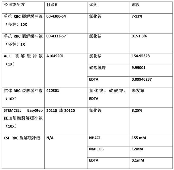
The RBC lysis zone 202 includes a first inlet 208 for receiving lysis buffer and a second inlet 201 for receiving whole blood. The whole blood and lysis buffer are combined in the mixer 102. As mentioned above, the mixer 102 may be a serpentine mixer or other type of mixer that allows the lysis buffer and red blood cells to mix for a period of time sufficient to lyse the red blood cells without lysing other cells or particles (including cells or particles of interest). Examples of commercially available lysis buffers are described in table 1 below. The lysis buffer injected into inlet 208 may be one of the lysis buffers described in table 1, or other lysis buffers.
Table 1: lysis buffer
After exiting the mixer, the whole blood enters the buffer exchanger 104 at the buffer exchanger input 212. Buffer exchanger 104 comprises a membrane through which cells cannot pass, but through which smaller components (such as ions, sugars, and proteins) can diffuse freely. Buffer exchanger 104 is discussed in more detail with respect to fig. 2B, which fig. 2B shows a side view of buffer exchanger 104. As shown in fig. 2A, the buffer exchanger includes a membrane support grid 214. DEP buffer can be injected at the DEP buffer input port 216 and flow through the membrane to exit at the waste port 218. It will be appreciated that the buffer exchanger may be operated in either a forward flow or a reverse flow exchange mode. In the counter-current exchange mode, DEP buffer is injected at port 218 and flows through the membrane to exit at port 216. Examples of DEP buffer chemistry are further described with respect to fig. 4.
The buffer-exchanged blood at the output 220 of the buffer exchanger 104 may be referred to herein as a solution comprising cells. The amount of lysis buffer in the solution comprising the cells will be significantly reduced or eliminated, thereby preventing further lysis that might otherwise affect the cells of interestAnd (4) cells. The solution containing cells at the output of the buffer exchanger 104 will also have a significant amount of red blood cells lysed and eliminated. In some examples, the red blood cell concentration may be from about 10 per milliliter9The individual red blood cells are reduced to about 10 per ml6Individual red blood cells. Thus, to analyze one milliliter of blood, the apparatus need only be paired with 106Individual cells were classified, not 109And thus increase the throughput of the device by a factor of 1000.
After the buffer exchanger 104, the solution containing the cells may enter the dilution section 204. At dilution section 204, additional DEP buffer is injected into the cell-containing solution through port 222 to further dilute the cell-containing solution. In some examples, the dilution may achieve a cell concentration (cell volume/buffer volume) of less than one percent. In some examples, a cell counter 224 may be disposed between the output 220 of the buffer exchanger and the port 22 of the dilution section 204. A cell counter 224 can be used to count the cells exiting the buffer exchanger 204 to determine the cell concentration. To achieve the target cell concentration, the cell counter 224 can be used to measure the cell concentration of the solution exiting the buffer exchanger 220, and the measured cell concentration can be used to control the amount of DEP buffer injected into the port 22 of the dilution section 204.
The solution containing the diluted cells exits dilution section 204 and enters particle focuser 206. The particle focuser comprises two DEP buffer inlets 226. The DEP buffer injected into the DEP buffer inlet meets the solution containing the cells at the inlet passage 228 of the separator 106. Particle focuser 206 focuses particles entrained in the solution containing cells into a laminar flow within inlet passage 228 prior to separation. In the example shown in fig. 2, the particle focuser 206 is a hydrodynamic focuser that uses first and second sheath flows of DEP buffer solution to sandwich the cell-containing solution to provide a laminar flow of particles through the inlet passage 228. In other embodiments, other particle focusers may be used, such as a free-flow negative dielectrophoresis particle focuser and a free-flow isotachophoresis particle focuser. Focusing the particles improves the accuracy of DEP separation by improving the consistency of the DEP force exerted on the particles. In some examples, the focuser 206 may be eliminated, and the solution containing the cells may enter the DEP separator 106 directly from the dilution section.
The focused particle stream enters the inlet passage 228 of the DEP separator 106. In the example shown in fig. 2, the separator 106 includes an inlet passage 228, a first separation passage 230, and a second separation passage 232. Separation channels 230 and 232 comprise channels, such as microfluidic channels that extend and branch from inlet channel 228. The separation pathways 230 and 232 lead to output wells 234 and 236 where the separated particles or cells can be collected and analyzed. Although passages 234 and 236 are illustrated as branching off from inlet passage 228 at an angle of approximately 135 degrees, it should be appreciated that passages 234 and 236 may extend from inlet passage 228 at other angles. Additionally, the separator 106 may include additional separation passages and additional output wells than shown on fig. 2. For example, in some embodiments, particles directed to separation pathways 230 and 232 may be further separated downstream.
The example separator 106 also includes electrodes 238, 240, and 242 that create an electric field across the pathways 228, 230, and 232. Electrodes 238, 240, and 242 extend in a single plane such that they generate an electric field that extends in the same plane as vias 228, 230, and 232. In the example shown in fig. 2, electrode 238 is a grounded electrode extending alongside vias 228 and 232, electrode 240 extends alongside vias 228 and 230, and electrode 242 extends alongside vias 230 and 232. The electrodes 240, 242 may have opposite polarities. For example, electrode 240 may be a positive electrode and electrode 242 may be a negative electrode, or vice versa. Each of the electrodes 238, 240, and 242 may be a continuous electrode or may be formed from a plurality of separate elements connected to ground or a current source, such as an alternating frequency current source.
In some examples, electrodes 238 and 240 are separated by a distance across inlet passageway 228 that is at least 10 times the diameter of the target particles to be separated. Likewise, electrodes 240 and 242 and electrodes 238 and 242 are also separated by a distance across separation pathways 230 and 232, respectively, that is at least 10 times the diameter of the target particle being separated.
Fig. 2B is a side view of a particle separation chip according to an example. The membrane of the buffer exchanger 104 of figure 2B is shown with reference numeral 244. The membrane 244 may be a 1000 kilodaltons (kDa) cut cellulose dialysis membrane. One side of the membrane 244 is a channel for whole blood flow, while the other side is a channel for DEP dialysis buffer flow. The buffer is isotonic with respect to blood so as not to lyse cells of interest, such as nucleated circulating tumor cells, nucleated red blood cells, and white blood cells. The buffer exchanger can be operated in either a forward flow or a counter-flow exchange mode.
The particle separation chip 200 may be coupled to a particle separation system, such as the particle separation system shown in fig. 3. The particle separation system controls the flow of fluids (such as whole blood and various buffers) through the particle separation chip at a particular flow rate. The flow rate will depend on various factors, including the size of the various components of the particle separation chip 200.
For example, the buffer exchanger 104 can be sized and controlled to provide a solution comprising cells at the output of the buffer exchanger having a conductivity of about 0.3 millisiemens per centimeter (mS/cm). The conductivity of whole blood is about 15-20 mS/cm, and blood is splitThe conductivity of the solution is substantially similar. For example, 100 mM ammonium chloride has a conductivity of 13 mS/cm. Thus, to achieve 0.3 mS/cm of the solution comprising the cells, the buffer exchanger can dialyze the whole blood against a volume of DEP buffer approximately equal to 100 times the volume of the whole blood. Thus, the flow rate of DEP buffer (referred to herein as Q) entering buffer exchanger 104 at input 216D) Will be greater than or equal to the whole blood flow rate (referred to herein as Q) entering the buffer exchanger at input 212BL) 100 times of the total weight of the powder.
Residence time of blood in buffer exchanger 104 Can be calculated according to the following formula:
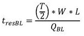
in the above formula, W is the width of the buffer exchanger, L is the length of the buffer exchanger, and T/2 is the overall thickness of the whole blood channel in the buffer exchanger, as shown in FIGS. 2A and 2B. Residence time to achieve the desired blood conductivity Should be equal to or greater than the total time for diffusion of ions and sugars from the blood into the buffer and from the buffer into the blood
 The time may be determined according to the following formula:
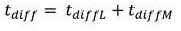
in the above-mentioned formula, the first and second, represents the total time of diffusion through the liquid, an
 Representing the total time of diffusion through the membrane. Additionally, the determination may be made according to the following formula
 :
:
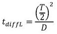
In the above-mentioned formula, the first and second,Dis the diffusivity of the slowest diffusing species. In the case of sucrose, the sugar may,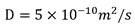 . The time of diffusion through the membrane can be modeled as a first approximation
 WhereinkIs a constant that scales with the thickness of the membrane and the permeability of the membrane. Depending on the nature of the film, it is,
 or
or Predominantly. In some examples, the film thickness may be selected such that
 And
And are comparable such that
 . As mentioned above, for the buffer exchanger to work properly,
 . This leads to the following relationship:
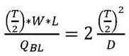
the simplification of the above formula yields:
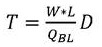
based on the above equations, the example buffer exchanger 104 can be constructed and operated according to the values shown in table 2 below.
Table 2: example buffer exchanger design
| Parameter(s) | Value of |
 |
0.005 ml/min |
 |
0.5 ml/min |
| W | 1 cm |
| L | 2 cm |
| T | 1.2 mm (or smaller) |
| k | 0.36 mm2 |
The particle separation chip 200 may be manufactured according to any suitable manufacturing technique. In some examples, the particle separation chip 200 may be fabricated as a silicon or polymer substrate with a glass plate coupled to the top surface. Suitable polymers may include Cyclic Olefin Copolymers (COC), polycarbonates, acrylic, teflon, nitrocellulose, polyether ketones (PEEK), and other polymers. The channels in the substrate may be formed by cutting, ablating, etching or other material removal processes carried out on the material layer(s) forming the substrate. The channels may also be formed by selective deposition, such as printing or additive manufacturing processes carried out on an underlying base layer or platform. The channels in the substrate may also be hot stamped or formed by injection molding to form a Molded Interconnect Device (MID). The electrodes 238, 240, and 242 may be formed by vapor deposition or sputtering of a conductive material such as copper or gold, among other suitable techniques.
Fig. 3 is a block diagram of a particle separation system according to an example. Particle separation system 300 includes particle separation apparatus 200, as well as various hardware that may be controlled to deliver fluid to the particle separation apparatus and direct the processes performed to effect particle separation. The particle separation apparatus 200 may be in the form of a cartridge or chip that may be inserted into a container of the particle separation system 300.
The example particle separation system 300 shown in fig. 3 includes a multi-channel pressure controller 302 to control the delivery of various fluids to the particle separation apparatus 200. The multi-channel pressure controller 302 is coupled to a plurality of vessels containing fluids, including a blood vessel 304 containing whole blood, a lysis buffer vessel 306, and a plurality of DEP buffer vessels 308. A multi-channel pressure controller 302 controls the injection of fluid from vessels 304, 306 and 308 into the particle separation apparatus 200. For example, the multi-channel pressure controller 302 may operate by delivering a pressurized gas (such as air or nitrogen) to the headspace of the vessels 304, 306, and 308. Each output of the multi-channel pressure controller 302 may be individually controlled to deliver different fluid injection rates depending on the design details of the particular implementation.
Additionally, each vessel 304, 306, and 308 may be coupled to a flow meter 310, which flow meter 310 senses the actual flow rate. The flow meter 310 may be of any suitable type, including a thermal pulse flow meter, as well as others. The flow meter 310 may provide a feedback signal corresponding to the measured flow rate back to the multi-channel pressure controller 302. This feedback loop enables the multi-channel pressure controller 302 to accurately control the flow rate.
The controller 302 may include a processor, which may be a microprocessor, a multi-core processor, a multi-threaded processor, an ultra-low voltage processor, an embedded processor, or other type of processor. The processor 1202 may be an integrated microcontroller, with the processor 1202 and other components formed on a single integrated circuit board or a single integrated circuit, such as a system on a chip (SoC). As an example, processors 1202 may comprise processors from Intel corporation of Santa Clara, CA, such as Quark ™ processors, Atom ™ chambers, i3, i5, i7 or MCU grade processors. Other processors that may be used may be available from advanced micro device corporation (AMD) of CA senivir, MIPS-based designs from MIPS technologies of CA senivir, ARM-based designs licensed from ARM holdings limited, or customers thereof, or licensees or adopters thereof. The processors may comprise units such as A5-A10 processors from Apple @, Inc., Snapdagon processors from Qualcomm technologies, Inc., or OMAP processors from Texas instruments, Inc.
The controller 302 may be in communication with a computer-readable medium 322, which computer-readable medium 322 may include any type and number of memory devices provided for a given amount of system memory. The computer-readable medium 322 may be implemented using volatile or non-volatile memory devices such as Random Access Memory (RAM), Solid State Drives (SSD), flash memory such as SD cards, microSD cards, xD picture cards, USB flash drives, hard drives, and the like.
The controller 320 may also include or be coupled to a user interface 324. For example, the user interface 324 may include a display panel and an input device, such as a touch screen or keypad, among other display panels and input devices. User interface 324 enables a user of particle separation system 300 to interact with particle separation system 300 and implement the functionality of particle separation system 300, as described herein.
Fig. 4 is a graph showing a relationship between cell crossover frequency and buffer conductivity according to an example. As explained above, dielectrophoretic separation is a process in which an electric field generates dielectrophoretic forces on cells and other particles within a solution. The degree and direction of the dielectrophoretic force depends on the conductivity of the solution containing the cells, the frequency of the AC signal and the electrical properties of the cells. Thus, proper selection of the conductivity and AC signal frequency of the solution containing the cells enables an operator of the particle separation system 300 to target a particular type of cell.
To ensure cell viability and general health, the DEP buffer may be a phosphate-based buffer at pH7 with various components to reduce cell stress. For example, sugars (such as sucrose and glucose) may be added to balance the osmotic pressure of the solution containing the cells and to provide a source of energy for the cells. Other components that may be added include pluronic acid, which protects cells from flow damage, and bis (trimethylsilyl) acetamide (BSA), which minimizes cell adhesion. Additionally, the DEP buffer may include catalase to reduce free radical production and subsequent damage. DEP buffers may also include calcium acetate and magnesium acetate to stabilize the integrity of the membrane. One example of a DEP buffer that can be used in the described technology includes 9.5% sucrose, 0.1mg/ml glucose, 0.1% Pluronic F68, 0.1% bovine serum albumin, 1mM phosphate buffer pH7, 0.1mM calcium acetate, 0.5mM magnesium acetate, and 100 units/ml catalase. The conductivity of the DEP buffer can be varied by varying the concentration of the phosphate buffer, wherein a higher concentration of phosphate buffer results in a higher conductivity, and vice versa.
Fig. 5 is a block diagram summarizing a method of separating particles of interest from whole blood according to an example. The method 500 may be performed by a particle separation system, such as the particle separation system 300 described above with respect to fig. 3. The method 500 may begin at block 502.
At block 502, whole blood is injected into a first inlet of a particle separation chip. At block 504, a lysis buffer is injected into a second inlet of the particle separation chip. At block 506, the whole blood is passed through a mixer of the particle separation chip. The mixer mixes the whole blood with a lysis buffer to lyse red blood cells in the whole blood.
At block 508, the whole blood passes through a buffer exchanger coupled to the output of the mixer to exchange lysis buffer to dielectrophoresis buffer, thereby generating a solution that enables dielectrophoretic separation of the particles of interest. In some examples, the buffer exchanger includes two channels separated by a semipermeable dialysis membrane. Whole blood flows through one channel and dielectrophoretic buffer flows through the other channel.
At block 510, the solution passes through a separator coupled to an output of the buffer exchanger to separate the particles of interest from other particles in the solution via dielectrophoretic separation.
At block 512, the particles of interest are delivered to an outlet on a particle separation chip. In some examples, the separator includes a particle focuser that receives an additional supply of dielectrophoretic buffer and focuses the particles of interest into a laminar flow. Additionally, the separator may be operated by applying an AC electric field to the solution containing the cells in the separator. The frequency of the AC electric field may be selected to target the particle of interest.
The method 500 should not be construed as implying that the blocks are necessarily performed in the order shown. Additionally, fewer or more actions may be included in method 500 depending on design considerations of a particular implementation. For example, another supply of dielectrophoretic buffer may be injected at the output of the buffer exchanger to further dilute the solution.
While the present technology may be susceptible to various modifications and alternative forms, the examples discussed above have been shown by way of example. It should be understood that the techniques are not intended to be limited to the particular examples disclosed herein. Indeed, the present technology includes all alternatives, modifications, and equivalents falling within the scope of the present technology.
Claims (15)
1. A particle separation chip, comprising:
a first inlet on the particle separation chip for receiving whole blood;
a second inlet on the particle separation chip for receiving a lysis buffer;
a mixer for mixing whole blood with a lysis buffer to provide lysis of red blood cells in the whole blood;
a buffer exchanger coupled to an output of the mixer to exchange the lysis buffer to a dielectrophoresis buffer, thereby producing a solution that enables dielectrophoretic separation of the particles of interest; and
a separator coupled to an output of the buffer exchanger to separate the particles of interest from other particles in the solution via dielectrophoretic separation and deliver the particles of interest to an outlet on the particle separation chip.
2. The particle separation chip of claim 1, wherein the buffer exchanger comprises:
a first channel through whole blood flow;
a second channel for buffering liquid flow by dielectrophoresis; and
a semi-permeable membrane separating the first channel and the second channel.
3. The particle separation chip of claim 1, comprising a third inlet on the particle separation chip for receiving a second supply of dielectrophoretic buffer at an output of the buffer exchanger to further dilute the solution.
4. A particle separation chip according to claim 1, comprising a fourth inlet on the particle separation chip for receiving a third supply of dielectrophoretic buffer, wherein the third supply of dielectrophoretic buffer is delivered to the particle focuser for focusing the particles of interest into a laminar flow.
5. The particle separation chip of claim 1, wherein the separator comprises electrodes that apply an Alternating Current (AC) electric field to the solution, wherein a frequency of the AC electric field is adjustable to target particles of interest.
6. A method of separating particles of interest from whole blood, comprising:
injecting whole blood into a first inlet of a particle separation chip;
injecting a lysis buffer into a second inlet of the particle separation chip;
passing the whole blood through a mixer of the particle separation chip to mix the whole blood with a lysis buffer, thereby lysing red blood cells in the whole blood;
passing whole blood through a buffer exchanger coupled to an output of the mixer to exchange lysis buffer to dielectrophoresis buffer, thereby producing a solution that enables dielectrophoretic separation of particles of interest; and
passing the solution through a separator coupled to an output of the buffer exchanger to separate the particles of interest from other particles in the solution via dielectrophoretic separation; and
delivering the particles of interest to an outlet on a particle separation chip.
7. The method of claim 6, wherein passing whole blood through a buffer exchanger comprises:
passing whole blood through a first channel; and
the dielectrophoretic buffer solution is passed through a second channel separated from the first channel by a semi-permeable membrane.
8. The method of claim 6, comprising injecting a second supply of dielectrophoresis buffer at an output of the buffer exchanger to further dilute the solution.
9. The method of claim 6, comprising injecting a third supply of dielectrophoretic buffer into the particle focuser to focus the particles of interest into a laminar flow.
10. The method of claim 6, comprising applying an Alternating Current (AC) electric field to the solution in the separator, wherein a frequency of the AC electric field is selected to target the particles of interest.
11. A particle separation system, comprising:
a container for receiving the particle separation chip;
a signal generator for supplying an Alternating Current (AC) electric signal to the electrodes of the particle separation chip to generate a dielectrophoretic force;
a fluid delivery system configured to provide a plurality of fluids to a particle separation chip, wherein the fluid delivery system is to:
injecting whole blood into a first inlet of a particle separation chip;
injecting a lysis buffer into a second inlet of the particle separation chip, wherein the lysis buffer is to lyse red blood cells in whole blood; and
a dielectrophoresis buffer is injected into the third inlet of the particle separation chip to dialyze the whole blood, thereby replacing the lysis buffer with the dielectrophoresis buffer to produce a solution that enables dielectrophoretic separation of the particles of interest from the whole blood due to the dielectrophoretic force.
12. The particle separation system of claim 11, wherein the third inlet is coupled to a buffer exchanger comprising:
a first channel through whole blood flow;
a second channel for buffering liquid flow by dielectrophoresis; and
a semi-permeable membrane separating the first channel and the second channel.
13. A particle separation system as claimed in claim 11, comprising a fourth inlet on the particle separation chip for receiving a second supply of dielectrophoretic buffer to further dilute the solution after dialysis of the whole blood.
14. A particle separation system according to claim 11, comprising a fifth inlet on the particle separation chip for receiving a third supply of dielectrophoretic buffer, wherein the third supply of dielectrophoretic buffer is delivered to the particle focuser for focusing the particles of interest into a laminar flow.
15. A particle separation system according to claim 11, wherein said AC electric field is adjustable to target particles of interest.
Applications Claiming Priority (1)
| Application Number | Priority Date | Filing Date | Title |
|---|---|---|---|
| PCT/US2018/052465 WO2020068041A1 (en) | 2018-09-24 | 2018-09-24 | Particle separation from whole blood |
Publications (1)
| Publication Number | Publication Date |
|---|---|
| CN112740024A true CN112740024A (en) | 2021-04-30 |
Family
ID=69950116
Family Applications (1)
| Application Number | Title | Priority Date | Filing Date |
|---|---|---|---|
| CN201880097962.XA Pending CN112740024A (en) | 2018-09-24 | 2018-09-24 | Particle isolation from whole blood |
Country Status (4)
| Country | Link |
|---|---|
| US (1) | US20210205812A1 (en) |
| EP (1) | EP3857215A4 (en) |
| CN (1) | CN112740024A (en) |
| WO (1) | WO2020068041A1 (en) |
Families Citing this family (1)
| Publication number | Priority date | Publication date | Assignee | Title |
|---|---|---|---|---|
| JP2025006982A (en) * | 2023-06-30 | 2025-01-17 | 株式会社Screenホールディングス | Flow Channel Chip |
Citations (8)
| Publication number | Priority date | Publication date | Assignee | Title |
|---|---|---|---|---|
| EP0171676A2 (en) * | 1984-07-31 | 1986-02-19 | Hitachi, Ltd. | Free-flow electrophoretic separation method and apparatus therefor |
| WO1998010267A1 (en) * | 1996-09-04 | 1998-03-12 | Technical University Of Denmark | A micro flow system for particle separation and analysis |
| US20040233424A1 (en) * | 2003-05-21 | 2004-11-25 | National Cheng Kung University | Chip-based microfluidic particle detector with three dimensional focusing mechanisms |
| CN103353476A (en) * | 2008-04-03 | 2013-10-16 | 加利福尼亚大学董事会 | Ex-vivo multi-dimensional system for the separation and isolation of cells, vesicles, nanoparticles and biomarkers |
| CN104797340A (en) * | 2012-09-21 | 2015-07-22 | 麻省理工学院 | Micro-fluidic device and uses thereof |
| US20170184545A1 (en) * | 2015-12-28 | 2017-06-29 | International Business Machines Corporation | Operation of diagnostic devices involving microchannels and electrodes |
| WO2017131162A1 (en) * | 2016-01-29 | 2017-08-03 | 株式会社Afiテクノロジー | Analysis device and separation device |
| US20170248512A1 (en) * | 2014-06-27 | 2017-08-31 | The Regents Of The University Of California | Apparatus and method for label-free analysis of rare cells from bodily fluids |
-
2018
- 2018-09-24 US US17/255,789 patent/US20210205812A1/en not_active Abandoned
- 2018-09-24 CN CN201880097962.XA patent/CN112740024A/en active Pending
- 2018-09-24 WO PCT/US2018/052465 patent/WO2020068041A1/en not_active Ceased
- 2018-09-24 EP EP18935011.9A patent/EP3857215A4/en active Pending
Patent Citations (9)
| Publication number | Priority date | Publication date | Assignee | Title |
|---|---|---|---|---|
| EP0171676A2 (en) * | 1984-07-31 | 1986-02-19 | Hitachi, Ltd. | Free-flow electrophoretic separation method and apparatus therefor |
| US4749458A (en) * | 1984-07-31 | 1988-06-07 | Hitachi, Ltd. | Free-flow electrophoretic separation method and apparatus therefor |
| WO1998010267A1 (en) * | 1996-09-04 | 1998-03-12 | Technical University Of Denmark | A micro flow system for particle separation and analysis |
| US20040233424A1 (en) * | 2003-05-21 | 2004-11-25 | National Cheng Kung University | Chip-based microfluidic particle detector with three dimensional focusing mechanisms |
| CN103353476A (en) * | 2008-04-03 | 2013-10-16 | 加利福尼亚大学董事会 | Ex-vivo multi-dimensional system for the separation and isolation of cells, vesicles, nanoparticles and biomarkers |
| CN104797340A (en) * | 2012-09-21 | 2015-07-22 | 麻省理工学院 | Micro-fluidic device and uses thereof |
| US20170248512A1 (en) * | 2014-06-27 | 2017-08-31 | The Regents Of The University Of California | Apparatus and method for label-free analysis of rare cells from bodily fluids |
| US20170184545A1 (en) * | 2015-12-28 | 2017-06-29 | International Business Machines Corporation | Operation of diagnostic devices involving microchannels and electrodes |
| WO2017131162A1 (en) * | 2016-01-29 | 2017-08-03 | 株式会社Afiテクノロジー | Analysis device and separation device |
Also Published As
| Publication number | Publication date |
|---|---|
| WO2020068041A1 (en) | 2020-04-02 |
| EP3857215A1 (en) | 2021-08-04 |
| EP3857215A4 (en) | 2022-06-22 |
| US20210205812A1 (en) | 2021-07-08 |
Similar Documents
| Publication | Publication Date | Title |
|---|---|---|
| Wu et al. | Label-free multitarget separation of particles and cells under flow using acoustic, electrophoretic, and hydrodynamic forces | |
| US20210155889A1 (en) | End-to-end cell therapy bioprocessing device for continuous-flow enrichment, washing, and electrotransfection of target cells | |
| US10670508B2 (en) | Microfluidic device for selection of semen | |
| JP5018879B2 (en) | Component separation device | |
| CN110366451B (en) | particle separation | |
| CN103354903B (en) | Measurement chip, microfluidic device and method | |
| Tanaka et al. | Separation of cancer cells from a red blood cell suspension using inertial force | |
| CN103403547A (en) | Counting particles using an electrical differential counter | |
| Ali et al. | Numerical study on the complete blood cell sorting using particle tracing and dielectrophoresis in a microfluidic device | |
| US20140339088A1 (en) | Dielectrophoresis methods for determining a property of a plurality of cancer cells | |
| Lee et al. | An integrated microfluidic platform for size-selective single-cell trapping of monocytes from blood | |
| KR101511569B1 (en) | Particle separation apparatus | |
| US12036555B2 (en) | Microfluidic particle sorting apparatus and manufacturing method thereof | |
| CN104031819A (en) | Flow Channel Device And Sorting Apparatus | |
| CN108369178A (en) | The micro- characterizing arrangement of fluid processing and method | |
| CN112740024A (en) | Particle isolation from whole blood | |
| US20140102948A1 (en) | High efficiency particle separating apparatus and method | |
| Xu et al. | Sequential ensemble-decision aliquot ranking isolation and fluorescence in situ hybridization identification of rare cells from blood by using concentrated peripheral blood mononuclear cells | |
| CN110106069A (en) | A kind of biochip based on fluid dynamic label-free separation cancer cell | |
| Ramya et al. | Microfluidic circulating tumour cell sorter using deterministic lateral displacement | |
| JP2004097886A (en) | Micro separation apparatus and separating method using the same | |
| KR100942364B1 (en) | Fine particle separator | |
| Lee et al. | Author Affiliations | |
| EP3300805B1 (en) | Microdevice for capturing particles, and method for capturing, concentrating, or separating particles using the same | |
| US11364503B2 (en) | Dielectrophoresis separators with cell ejection devices |
Legal Events
| Date | Code | Title | Description |
|---|---|---|---|
| PB01 | Publication | ||
| PB01 | Publication | ||
| SE01 | Entry into force of request for substantive examination | ||
| SE01 | Entry into force of request for substantive examination | ||
| WD01 | Invention patent application deemed withdrawn after publication | ||
| WD01 | Invention patent application deemed withdrawn after publication |
Application publication date: 20210430 |