CN112674819B - Suture auxiliary operation instrument and operation method thereof - Google Patents
Suture auxiliary operation instrument and operation method thereof Download PDFInfo
- Publication number
- CN112674819B CN112674819B CN202110056822.1A CN202110056822A CN112674819B CN 112674819 B CN112674819 B CN 112674819B CN 202110056822 A CN202110056822 A CN 202110056822A CN 112674819 B CN112674819 B CN 112674819B
- Authority
- CN
- China
- Prior art keywords
- locking
- suture
- thread trimming
- state
- thread
- Prior art date
- Legal status (The legal status is an assumption and is not a legal conclusion. Google has not performed a legal analysis and makes no representation as to the accuracy of the status listed.)
- Active
Links
Images


Landscapes
- Materials For Medical Uses (AREA)
- Surgical Instruments (AREA)
Abstract
The application provides a suture auxiliary operation instrument and an operation method thereof, and the suture auxiliary operation instrument comprises a locking device with a locking structure and a locking control structure and a suture cutting device with a suture cutting structure and a suture cutting control structure, wherein the locking control structure can move relative to the locking structure to control the locking structure to lock a suture thread which is arranged in a penetrating mode, and the suture cutting control structure can move relative to the suture cutting control structure to control the suture cutting structure to cut the suture thread. Borrow this application has easy operation, and the high advantage of the locking reliability of stylolite to can improve the operational safety nature.
Description
Technical Field
The embodiment of the application relates to the technical field of medical instruments, in particular to a suture auxiliary operating instrument and an operating method thereof.
Background
With the increasing prevalence of minimally invasive and interventional procedures, knotting or locking of sutures in patients is often required during the procedure, i.e., locking of such sutures generally needs to be accomplished in a small, flexible, remote passageway.
The prior art discloses a suture locking device that uses a rigid collet to clamp a locking pin to achieve the purpose of locking the suture. However, when such a locking device is required for smaller access, the clamping force provided by the locking device is insufficient to clamp the suture due to part size limitations. Alternatively, the risk of surgery is increased due to the unreliable locking effect provided by the locking device. In addition, due to the fact that the existing locking device is large in number of parts, complex in matching relation and complex in device manufacturing process, the technical problems also limit further reduction of the size of the parts; in addition, the suture locking and the thread cutting provided by the existing locking device are simultaneously completed through one driving action, and the repeatability of the locking action cannot be met when the locking position is not excellent.
In view of the above, there is a need for a suture thread assisting operation instrument which can improve the suture thread locking reliability, has a simple structural design, and is suitable for a small operation space.
Disclosure of Invention
In view of the above, the present application provides a suture-assist operating instrument and a method of operating the same to overcome or at least partially solve the above problems.
The present application provides a suture thread auxiliary operation instrument, it includes: the locking device is provided with a locking structure and a locking control structure, wherein the locking control structure can move back and forth relative to the locking structure so as to control the locking structure to lock the suture or provide the suture to move relative to the locking structure; and the thread cutting device can be used for the suture thread to penetrate through and is provided with a thread cutting structure and a thread cutting control structure, and the thread cutting control structure can move relative to the thread cutting structure so as to control the thread cutting structure to cut off the suture thread.
Optionally, the locking control structure is reciprocally movable along an axial direction thereof relative to the locking structure to control the locking structure to be reciprocally switched between an unlocked state and a locked state, wherein the suture is movable relative to the locking structure when the locking structure is in the unlocked state, and the suture is lockable when the locking structure is in the locked state; and the thread trimming control structure can move relative to the thread trimming structure along the axial direction of the thread trimming control structure so as to control the thread trimming structure to be switched from a non-thread trimming state to a thread trimming state, wherein when the thread trimming structure is in the non-thread trimming state, the suture thread can move relative to the thread trimming structure, and when the thread trimming structure is in the thread trimming state, the suture thread can be trimmed.
Optionally, the locking structure comprises a locking portion, and the locking control structure comprises a first accommodating portion for accommodating the locking structure; wherein the locking portion is in the unlocked state in an unstressed state so that the suture thread moves relative to the locking portion; when the locking control structure moves axially relative to the locking structure, so that the locking structure gradually enters the first accommodating part, acting force is applied to at least one part of the locking part by the locking control structure, and the locking part is deformed and gradually switched from the non-locking state to the locking state to lock the suture.
Optionally, the locking part comprises a plurality of sawtooth engaging units for engaging the suture thread, so that the suture thread in the locking state is in a Z-shaped folding state or a snake-shaped folding state, and the engaging heights of the sawtooth engaging units are the same or different.
Optionally, the locking structure further comprises a first limiting portion adjacent to the locking portion for limiting the suture to be positioned at a preset position of the locking portion.
Optionally, the first limiting part is a limiting hole arranged at a side part of the locking part.
Optionally, the locking device further includes a positioning structure respectively disposed on an inner sidewall of the first accommodating portion and an outer sidewall of the locking structure, and the positioning structure is configured to provide that the locking structure is positioned in the first accommodating portion, so that the locking portion maintains the locked state.
Optionally, the locking control structure further includes a first sleeve having a first clamping portion, a second sleeve having a second clamping portion, and a mandrel; when the mandrel penetrates through the first sleeve and the second sleeve, the first clamping part and the second clamping part can be in a clamping state, so that the first sleeve and the second sleeve are connected into a whole; when the mandrel is drawn out from the first sleeve and the second sleeve, the clamping state of the first clamping part and the second clamping part can be released, so that the first sleeve and the second sleeve are mutually separated.
Optionally, the locking device further comprises a connecting structure respectively arranged on the locking structure and the mandrel, and is used for providing that the mandrel is detachably and coaxially connected with the locking structure; when the mandrel penetrates through the first sleeve and the second sleeve and is coaxially connected with the locking structure, the locking structure and the first accommodating part can be aligned in position with each other, so that the locking structure can gradually enter the first accommodating part; when the locking structure is positioned in the first accommodating part, only the first sleeve and the locking structure in the first accommodating part of the first sleeve can be reserved by removing the mandrel so that the second sleeve is removed together with the mandrel.
Optionally, the trimming structure includes a trimming portion, and the trimming control structure includes a second accommodating portion for accommodating the trimming structure; wherein the thread trimming portion is in the non-thread trimming state in a non-stressed state for movement of the suture thread relative to the thread trimming portion; when the trimming control structure moves axially relative to the trimming structure, so that the trimming structure gradually enters the second accommodating part, acting force is applied to at least one part of the trimming part by the trimming control structure, and the trimming part is deformed and gradually switched from the non-trimming state to the trimming state to trim the suture.
Optionally, the suture line cutting structure further includes a second limiting portion adjacent to the suture line cutting portion, and the second limiting portion is used for limiting the suture line to be positioned at a preset position of the suture line cutting portion.
Optionally, the second limiting portion is a limiting hole arranged at a side portion of the trimming portion.
Optionally, the locking device further includes a screw connection structure respectively disposed on an outer side wall of the locking structure and an inner side wall of the locking control structure, and configured to provide that the locking control structure rotates along a circumferential direction thereof relative to the locking structure, so that the locking control structure moves back and forth along an axial direction thereof relative to the locking structure, and the locking structure is switched back and forth between the non-locking state and the locking state; the thread trimming device further comprises a screw connection structure which is respectively arranged on the outer side wall of the thread trimming structure and the inner side wall of the thread trimming control structure and is used for providing that the thread trimming control structure rotates relative to the thread trimming structure along the circumferential direction of the thread trimming control structure so as to enable the thread trimming control structure to move relative to the thread trimming structure along the axial direction of the thread trimming control structure, and therefore the thread trimming structure is switched from the non-thread trimming state to the thread trimming state.
Optionally, the locking structure and the trimming structure are made of a memory alloy material, and the memory alloy material comprises a nickel-titanium alloy material.
Optionally, the thread trimming control structure and the locking control structure are designed in the same structure.
Another embodiment of the present application provides a method of operating a suture-assist operating instrument having a locking device and a thread cutting device, including: a suture is arranged in a locking device with a locking structure and a locking control structure in a penetrating way, and a mandrel of the locking control structure is coaxially connected with the locking structure; moving the locking control structure relative to the locking structure along the axial direction of the locking control structure, so that the locking structure at least partially enters a first sleeve of the locking control structure, and applying acting force to at least one part of the locking structure by virtue of the first sleeve, so that the locking structure is deformed and gradually switched from a non-locking state to a locking state, thereby locking the suture; removing the mandrel to cause the first and second sleeves of the locking control structure to disassociate from one another and removing the second sleeve while retaining only the first sleeve and the locking structure within the first sleeve; the suture line is arranged in a thread cutting device with a thread cutting structure and a thread cutting control structure in a penetrating mode, and a mandrel of the thread cutting control structure is coaxially connected with the thread cutting structure; moving the thread trimming control structure relative to the thread trimming structure, so that the thread trimming structure at least partially enters the thread trimming control structure, and applying an acting force to at least one part of the thread trimming structure by means of the thread trimming control structure, so that the thread trimming structure is deformed and gradually switched from a non-thread trimming state to a thread trimming state, and the suture thread is trimmed; and taking out the thread trimming device.
It can be seen from the above technical solutions that the suture thread auxiliary operation instrument of the embodiments of the present application can provide the locking control structure to reciprocate relative to the locking structure for repeatedly performing the locking operation of the suture thread, so as to adjust the locking position of the suture thread and improve the reliability of the locking of the suture thread.
Furthermore, this application can avoid the risk of not cutting under the circumstances that the stylolite is not locked through independently carrying out the locking operation and the trimming operation of stylolite, can increase the operational safety.
Drawings
In order to more clearly illustrate the embodiments of the present application or the technical solutions in the prior art, the drawings needed to be used in the description of the embodiments or the prior art will be briefly described below, it is obvious that the drawings in the following description are only some embodiments described in the embodiments of the present application, and other drawings can be obtained by those skilled in the art according to the drawings.
FIGS. 1 and 2 are schematic views of the suture-assist handling instrument of the present application in different states;
FIG. 3 is a side elevational view of the suture-assist operating instrument illustrated in FIG. 2 in a use configuration;
fig. 4A to 4C are schematic views of different embodiments of the locking structure of the present application;
FIG. 5 is a schematic view of an embodiment of the trimming structure of the present application;
fig. 6 to 9 are schematic views of an embodiment of a locking control structure/trimming control structure of the present application;
FIG. 10 is a schematic view of another embodiment of the locking device of the present application;
FIG. 11 is a schematic view of another embodiment of the thread trimming apparatus of the present application;
fig. 12A to 12E are schematic views illustrating an operation method of the suture assisting operation instrument of the present application.
Element number
1: a suture-assisted manipulation instrument;
2: a locking device;
21: a locking structure;
211: a locking portion;
211A: a saw tooth engaging unit;
212: a first limiting part;
22: a locking control structure;
221: a first receptacle portion;
222: a first sleeve;
2221: a first clamping part;
223: a second sleeve;
2231: a second clamping part;
224: a mandrel;
23: a positioning structure;
231: a groove;
232: a flange;
24: a connecting structure;
241: an external thread;
242: an internal thread;
25: a screw connection structure;
251: an external thread;
252: an internal thread;
3: a thread trimming device;
31: a thread trimming structure;
311: a trimming part;
312: a second limiting part;
32: a trimming control structure;
321: a second receptacle portion;
324: a mandrel;
35: a screw connection structure;
351: an external thread;
352: an internal thread;
4: and (4) sewing.
Detailed Description
In order to make those skilled in the art better understand the technical solutions in the embodiments of the present application, the technical solutions in the embodiments of the present application will be described clearly and completely below with reference to the drawings in the embodiments of the present application, and it is obvious that the described embodiments are only a part of the embodiments of the present application, but not all embodiments. All other embodiments obtained by a person of ordinary skill in the art based on the embodiments in the present application shall fall within the scope of the protection of the embodiments in the present application.
In view of the above problems in the background art, the conventional locking device has the problems of complicated structural design, unreliable locking of the suture, and the like, and the present application provides a suture auxiliary operating instrument, and the following will further explain the embodiments of the present application by referring to the drawings of the embodiments of the present application.
Referring to fig. 1 to 3, the suture assisting operation instrument 1 of the present embodiment is suitable for use in a transcatheter (not shown) or a minimally invasive use scenario, and mainly includes a locking device 2 and a thread cutting device 3.
The locking device 2 can provide a suture 4 to pass through and is provided with a locking structure 21 and a locking control structure 22, wherein the locking control structure 22 can be stressed to move in a reciprocating manner relative to the locking structure 21 so as to control the locking structure 21 to lock the suture 4 or provide a movement of the suture 4 relative to the locking structure 21 so as to adjust the locking position of the suture 4.
In this embodiment, the locking control structure 22 is reciprocally movable along its axial direction relative to the locking structure 21 to control the locking structure 21 to be reciprocally switched between the unlocked state and the locked state, wherein when the locking structure 21 is in the unlocked state, the suture 4 can be moved relative to the locking structure 21 to adjust the locking position of the suture 4, and when the locking structure 21 is in the locked state, the suture 4 can be positioned and locked. Therefore, the locking device 2 can provide the user with repeated locking operation of the suture 4, not only can flexibly adjust the locking position of the suture 4, but also can improve the locking reliability of the suture 4.
Referring to fig. 4A to 4C and fig. 6 to 9, the locking structure 21 of the present embodiment includes a locking portion 211, wherein the locking portion 211 is in a non-locking state (i.e., the state shown in fig. 1, 4A and 4B) when not stressed, and at least a portion of the locking portion 211 can be deformed when being subjected to an external force, so as to gradually switch from the non-locking state to the locking state (refer to the state shown in fig. 2 and 3).
Alternatively, the locking portion 211 may be made of a memory alloy material, such as nitinol, but not limited thereto, and other memory alloy materials may be used.
In this embodiment, after the locking device 21 is initially processed (for example, in the state shown in fig. 4C), the locking portion 211 in the locking device 21 is kept in the unlocked state (i.e., in the state shown in fig. 4B) by a shaping process, so that the locking portion 211 is kept in the unlocked state in the unstressed state.
However, it is not limited to this, and the locking portion 211 may be kept in the unlocked state after the initial processing of the locking device 21 is completed, so that the suture 4 can freely pass through the locking portion 211 in the opened state (unlocked state).
In the present embodiment, the locking portion 211 includes a plurality of saw-tooth engaging units 211A for engaging the suture 4, so that the suture 4 in the locked state can assume a Z-folded state or a serpentine folded state.
Preferably, each saw-tooth engaging unit 211A in the locking part 211 may not have the same or different engaging height, thereby further improving the locking reliability of the suture 4.
In this embodiment, the locking structure 21 may further include a first limiting portion 212, as shown in fig. 4A, the first limiting portion 212 may be disposed adjacent to the locking portion 211 for limiting the suture 4 to be positioned at a predetermined position of the locking portion 211, thereby preventing the suture 4 from falling off from the locking portion 211, which may result in the problem that the locking portion 211 cannot effectively lock the suture 4.
Alternatively, the first position-limiting portion 212 may be a position-limiting hole disposed at a side portion of the locking portion 211, but not limited thereto, and other position-limiting structures may also be adopted, which is not limited in this application.
In the embodiment, the locking control structure 22 includes a first accommodating portion 221 for accommodating the locking structure 21, and is configured to accommodate the locking structure 2 therein.
In this embodiment, the locking control structure 22 further includes a first sleeve 222, a second sleeve 223, and a core shaft 224 (refer to fig. 7 to 9).
The first sleeve 222 has a first clamping portion 2221, and the second sleeve 223 has a second clamping portion 2231.
In this embodiment, when the mandrel 224 is inserted into the first sleeve 222 and the second sleeve 223, the first clamping portion 2221 and the second clamping portion 2231 can be in a clamping state, and when the mandrel 224 is pulled out from the first sleeve 222 and the second sleeve 223, the clamping state between the first clamping portion 2221 and the second clamping portion 2231 can be released, that is, as shown in fig. 6, when the mandrel 224 penetrates through the first sleeve 222 and the second sleeve 223, the first clamping portion 2221 and the second clamping portion 2231 can be fixedly combined together, so that the first sleeve 222 and the second sleeve 223 are connected into a whole; when the mandrel 224 is pulled away from the first sleeve 222 and the second sleeve 223, the first snapping portions 2221 and the second snapping portions 2231 are naturally separated from each other, so that the first sleeve 222 and the second sleeve 223 are separated from each other.
In the present embodiment, the first accommodating portion 221 for accommodating the locking structure 21 is formed in the first sleeve 222 of the locking control structure 22.
In this embodiment, the locking device 2 further includes a positioning structure 23 disposed on the inner sidewall of the first receiving portion 221 and the outer sidewall of the locking structure 21, respectively, for providing the locking structure 21 to be positioned in the first receiving portion 221, so as to maintain the locking state of the locking portion 211.
For example, the positioning structure 23 includes a groove 231 disposed on the inner sidewall of the first receiving portion 221 and a flange 232 disposed on the outer sidewall of the locking structure 21, and the groove 231 and the flange 232 cooperate to limit the locking structure 21 from moving axially in the first receiving portion 221 relative to the first receiving portion 221, so as to ensure that the locking structure 21 is maintained in a locked state to lock the suture 4 passing therethrough.
In this embodiment, the locking device 2 further comprises a connecting structure 24 provided on the locking structure 21 and the spindle 224 respectively, for providing the spindle 224 to be detachably connected coaxially with the locking structure 21.
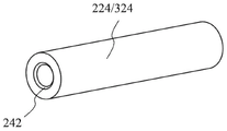
For example, the connecting structure 24 may include external threads 241 disposed at a proximal end of the locking structure 21 (i.e., an end of the locking structure 21 closer to the operator) and internal threads 242 disposed at a distal end of the mandrel 224 (i.e., an end of the mandrel 224 farther from the operator) to threadably connect the mandrel 224 coaxially with the locking structure 21.
In this embodiment, when the mandrel 224 is inserted into the first sleeve 222 and the second sleeve 223 and the internal thread 242 at the distal end of the mandrel 224 is screwed with the external thread 241 at the proximal end of the locking structure 21, the locking structure 21 and the first receiving portion 221 of the locking control structure 22 can be aligned with each other, so that when the integrally connected first sleeve 222 and the second sleeve 223 are moved back and forth along the axial direction thereof relative to the locking structure 21, the locking structure 21 can be gradually inserted into the first receiving portion 221 or removed from the first receiving portion 221.
Furthermore, when the locking structure 21 is located in the first receiving portion 221, only the first sleeve 222 and the locking structure 21 located in the first receiving portion 221 of the first sleeve 222 can be retained by removing the mandrel 224 so that the second sleeve 223 is removed along with the mandrel 224.
Specifically, the second sleeve 223 may be further removed by releasing the coaxial connection between the mandrel 224 and the locking structure 21 and withdrawing the mandrel 224 from the first sleeve 222 and the second sleeve 223, such that the first sleeve 22 and the second sleeve 223 are disengaged from each other, and only the first sleeve 222 of the locking control structure 22 and the locking structure 21 remain in the patient.
Referring to fig. 5, the thread-cutting structure 31 may include a thread-cutting portion 311, wherein the thread-cutting portion 311 is in a non-thread-cutting state (i.e., the state shown in fig. 1 and 5) in an unstressed state, so that the suture thread 4 moves relative to the thread-cutting portion 311; when an external force is applied to at least a portion of the trimming portion 311, the portion is deformed and gradually switched from the non-trimming state to the trimming state (refer to the states shown in fig. 2 and 3).
Alternatively, the wire-cutting portion 311 may be made of a memory alloy material, such as nitinol, but not limited thereto, and other memory alloy materials may be used.
In addition, as for the manufacturing process of the wire trimming portion 311, reference may be made to the above-mentioned related description regarding the manufacturing process of the locking portion 211, and therefore, no further description is given here.
Optionally, the thread trimming structure 31 further includes a second limiting portion 312 adjacent to the thread trimming portion 311 for limiting the position of the suture thread 4 at the preset position of the thread trimming portion 311, so that the suture thread 4 can be prevented from falling off from the thread trimming portion 311, which results in a problem that the thread trimming portion 311 cannot effectively trim the suture thread 4.
In the embodiment, the second position-limiting portion 312 may be a position-limiting hole disposed at a side portion of the wire-cutting portion 311, but not limited thereto, and other position-limiting structures may also be adopted, which is not limited in the present application.
In the present embodiment, the trimming control structure 32 and the locking control structure 22 can be designed in the same structure, so that the manufacturing process can be simplified to effectively reduce the manufacturing cost.
Specifically, the trimming control structure 32 includes a second receiving portion 321 (refer to fig. 6) for receiving the trimming structure 31, wherein when the trimming control structure 32 moves axially relative to the trimming structure 31 so that the trimming structure 31 gradually enters the second receiving portion 321, a force is applied to at least a portion of the trimming portion 311 by the trimming control structure 32, so that the trimming portion 311 deforms and gradually switches from the non-trimming state to the trimming state to trim the suture thread 4.
In the present embodiment, the components of the trimming control structure 32, the connection relationship and the actuation relationship between the trimming control structure 32 and the trimming structure 31 are substantially the same as the locking control structure 22 and the locking structure 21, and are not described herein again.
It should be noted that the sleeve portion of the thread cutting device 3 can be designed as a split design of the first sleeve 222 and the second sleeve 223, but not limited thereto, since the thread cutting device 3 of the present application is integrally removed to the outside of the patient after completing the cutting operation of the suture thread 4, the thread cutting control structure 32 can also change the split design of the first sleeve 222 and the second sleeve 223 into an integrated sleeve design.
In another embodiment, the locking device 2 further comprises a screw structure 25 respectively disposed on an outer side wall of the locking structure 21 and an inner side wall of the locking control structure 22 for providing rotation of the locking control structure 22 relative to the locking structure 21 along a circumferential direction thereof to reciprocate the locking control structure 22 relative to the locking structure 21 along an axial direction thereof to reciprocally switch the locking structure 21 between the unlocked state and the locked state.
Referring to fig. 10, the screw-coupling structure 25 of the locking device 2 may include an external thread 251 disposed on an outer sidewall of the locking structure 21 and an internal thread 252 disposed on an inner sidewall of the first accommodating portion 221 of the locking control structure 22, so that the locking control structure 22 reciprocates relative to the locking structure 21 along an axial direction thereof by rotating relative to the locking structure 21 along a circumferential direction thereof, thereby controlling the locking structure 21 to switch between the unlocked state and the locked state.
It should be noted that, with this structure, the design of the positioning structure 23 can be eliminated, and the self-locking function provided by the screw structure 25 of the locking device 2 can be used to replace the positioning function of the positioning structure 23.
In another embodiment, the thread trimming device 3 further includes a screw connection structure (35) respectively disposed on an outer sidewall of the thread trimming structure 31 and an inner sidewall of the thread trimming control structure 32, for providing the thread trimming control structure 32 to rotate along its circumferential direction relative to the thread trimming structure 31, so that the thread trimming control structure 32 moves along its axial direction relative to the thread trimming structure 31, and the thread trimming structure 31 is switched from the non-thread trimming state to the thread trimming state.
Referring to fig. 11, the screw structure 35 of the thread trimming device 3 may include an external thread 351 disposed on an outer sidewall of the thread trimming structure 11 and an internal thread 352 disposed on an inner sidewall of the second accommodating portion 321 of the thread trimming control structure 32, so that the thread trimming control structure 32 rotates relative to the thread trimming structure 31 along a circumferential direction thereof, so as to move the thread trimming control structure 32 relative to the thread trimming structure 31 along an axial direction thereof, and further control the thread trimming structure 31 to switch from the non-thread trimming state to the thread trimming state.
Referring to fig. 12A to 12E, which illustrate the operation method of the suture assisting operation instrument of the present application, the method of the present embodiment can be applied to a suture assisting operation instrument 1 having a locking device 2 and a thread cutting device 3, and mainly includes the following operation steps:
as shown in fig. 12A, suture 4 is threaded into locking device 2 having locking structure 21 and locking control structure 22, and core 224 of locking control structure 22 is coaxially connected with locking structure 21.
As shown in fig. 12B, the locking control structure 22 is moved relative to the locking structure 21 along the axial direction thereof, so that the locking structure 21 enters at least a part of the first sleeve 222 of the locking control structure 22, and the first sleeve 222 applies a force to at least a part of the locking structure 21, so that the locking structure 21 is deformed to gradually switch from the non-locking state to the locking state, thereby locking the suture 4.
Preferably, locking structure 21 is switchable between the unlocked state and the locked state by reciprocating locking control structure 22 in its axial direction relative to locking structure 21 for adjusting the locked position of suture 4.
As shown in fig. 12C, the mandrel 224 is removed to disengage the first sleeve 222 and the second sleeve 223 of the locking control structure 22 from each other, and the second sleeve 223 is further removed to leave only the first sleeve 222 and the locking structure 21 in the first sleeve 222 in the patient.
As shown in fig. 12D, the suture 4 is inserted into the thread cutting device 3 having the thread cutting structure 31 and the thread cutting control structure 32, the mandrel 324 of the thread cutting control structure 32 is coaxially connected to the thread cutting structure 31, and then the thread cutting control structure 32 is moved relative to the thread cutting structure 31, so that the thread cutting structure 31 at least partially enters the thread cutting control structure 32, and the thread cutting control structure 32 applies an acting force to at least a portion of the thread cutting structure 31, so that the thread cutting structure 31 is deformed and gradually switched from the non-thread cutting state to the thread cutting state, thereby cutting the suture 4.
As shown in fig. 12E, after the cutting operation of the suture 4 is completed, the thread cutting device 3 (including the thread cutting structure 31 and the thread cutting control structure 32) is removed from the patient.
To sum up, the suture auxiliary operation apparatus that this application provided utilizes locking structure and the trimming structure that memory alloy made, can realize the switching of different states to reduce part use quantity, make this application have simple, the convenient operation's of structural design advantage.
Furthermore, the locking device of this application can provide the repetitive operation of stylolite locking, is convenient for adjust the latched position of stylolite in a flexible way, in addition, utilizes the mode of folding stylolite to carry out the locking operation, can provide bigger locking force to improve the locking reliability of stylolite.
In addition, this application can avoid the suture to be cut off under the state of not locking through independently carrying out the locking operation and the operation of cutting off of suture, has improved the operational safety.
Finally, it should be noted that: the above embodiments are only used for illustrating the technical solutions of the embodiments of the present application, and are not limited thereto; although the present application has been described in detail with reference to the foregoing embodiments, it should be understood by those of ordinary skill in the art that: the technical solutions described in the foregoing embodiments may still be modified, or some technical features may be equivalently replaced; and such modifications or substitutions do not depart from the spirit and scope of the corresponding technical solutions in the embodiments of the present application.
Claims (14)
Priority Applications (1)
| Application Number | Priority Date | Filing Date | Title |
|---|---|---|---|
| CN202110056822.1A CN112674819B (en) | 2021-01-15 | 2021-01-15 | Suture auxiliary operation instrument and operation method thereof |
Applications Claiming Priority (1)
| Application Number | Priority Date | Filing Date | Title |
|---|---|---|---|
| CN202110056822.1A CN112674819B (en) | 2021-01-15 | 2021-01-15 | Suture auxiliary operation instrument and operation method thereof |
Publications (2)
| Publication Number | Publication Date |
|---|---|
| CN112674819A CN112674819A (en) | 2021-04-20 |
| CN112674819B true CN112674819B (en) | 2022-04-19 |
Family
ID=75458252
Family Applications (1)
| Application Number | Title | Priority Date | Filing Date |
|---|---|---|---|
| CN202110056822.1A Active CN112674819B (en) | 2021-01-15 | 2021-01-15 | Suture auxiliary operation instrument and operation method thereof |
Country Status (1)
| Country | Link |
|---|---|
| CN (1) | CN112674819B (en) |
Citations (6)
| Publication number | Priority date | Publication date | Assignee | Title |
|---|---|---|---|---|
| CN203914987U (en) * | 2014-06-13 | 2014-11-05 | 江苏唯德康医疗科技有限公司 | Stitching thread locking device |
| CN204016381U (en) * | 2014-07-17 | 2014-12-17 | 江苏唯德康医疗科技有限公司 | Axial cutting facility |
| CN104706391A (en) * | 2015-03-26 | 2015-06-17 | 诺琅医疗科技(上海)有限公司 | Gasket locking catheter capable of cutting suture line |
| CN110313951A (en) * | 2018-03-28 | 2019-10-11 | 杭州德晋医疗科技有限公司 | Suture lock and suture lock clone system |
| CN111839626A (en) * | 2019-04-30 | 2020-10-30 | 杭州德晋医疗科技有限公司 | Suture locking device with improved locking mode and suture lock catch thereof |
| CN112206021A (en) * | 2019-07-10 | 2021-01-12 | 杭州德晋医疗科技有限公司 | Intervention type remote suture locking device |
Family Cites Families (5)
| Publication number | Priority date | Publication date | Assignee | Title |
|---|---|---|---|---|
| JPS57170240A (en) * | 1981-04-14 | 1982-10-20 | Janome Sewing Machine Co Ltd | Suturing stitch constitution by suturing device for operation |
| US20060122633A1 (en) * | 2002-06-13 | 2006-06-08 | John To | Methods and devices for termination |
| US8888791B2 (en) * | 2008-10-07 | 2014-11-18 | Kardium Inc. | Surgical instrument and method for tensioning and securing a flexible suture |
| EP2696778B1 (en) * | 2011-04-11 | 2020-05-06 | St. Jude Medical Puerto Rico LLC | Suture locking device |
| WO2018081233A1 (en) * | 2016-10-25 | 2018-05-03 | Gittard Shaun Davis | Suture lock device |
-
2021
- 2021-01-15 CN CN202110056822.1A patent/CN112674819B/en active Active
Patent Citations (6)
| Publication number | Priority date | Publication date | Assignee | Title |
|---|---|---|---|---|
| CN203914987U (en) * | 2014-06-13 | 2014-11-05 | 江苏唯德康医疗科技有限公司 | Stitching thread locking device |
| CN204016381U (en) * | 2014-07-17 | 2014-12-17 | 江苏唯德康医疗科技有限公司 | Axial cutting facility |
| CN104706391A (en) * | 2015-03-26 | 2015-06-17 | 诺琅医疗科技(上海)有限公司 | Gasket locking catheter capable of cutting suture line |
| CN110313951A (en) * | 2018-03-28 | 2019-10-11 | 杭州德晋医疗科技有限公司 | Suture lock and suture lock clone system |
| CN111839626A (en) * | 2019-04-30 | 2020-10-30 | 杭州德晋医疗科技有限公司 | Suture locking device with improved locking mode and suture lock catch thereof |
| CN112206021A (en) * | 2019-07-10 | 2021-01-12 | 杭州德晋医疗科技有限公司 | Intervention type remote suture locking device |
Also Published As
| Publication number | Publication date |
|---|---|
| CN112674819A (en) | 2021-04-20 |
Similar Documents
| Publication | Publication Date | Title |
|---|---|---|
| EP1720457B1 (en) | Suture manipulating and cutting implement | |
| JP4094677B2 (en) | Biopsy forceps with removable handle and distal jaw | |
| AU2017322329B2 (en) | System for suture trimming | |
| US9801622B2 (en) | Expandable needle suture apparatus and associated handle assembly with rotational suture manipulation system | |
| CA2141911C (en) | Surgical crimping device and method of use | |
| CA2578197C (en) | Expandable needle suture apparatus and associated handle assembly with rotational suture manipulation system | |
| WO2013009382A1 (en) | Minimally invasive dilator and retractor system | |
| CN112674819B (en) | Suture auxiliary operation instrument and operation method thereof | |
| CN106725667A (en) | Minimally invasive manadesma closer | |
| CN115399821A (en) | A locking device and handle control system | |
| CN114617604A (en) | Minimally invasive integrated tissue cavity ligation system | |
| JP2022509536A (en) | Automatic suturing device and automatic suturing method | |
| CN209122328U (en) | A threading clip for surgical suture | |
| US20240268875A1 (en) | Methods and devices for orthopedic surgical techniques | |
| CN223845700U (en) | Medical wire cutting pliers | |
| CN119791748B (en) | An endoscopic suturing device | |
| CN113616258B (en) | Suture cutting tool used with minimally invasive surgical instrument | |
| TWI760736B (en) | Suture cutting knife used with minimally invasive surgical instrument | |
| CN113693656B (en) | Laparoscopic needle holder | |
| CN118614973A (en) | Suture locking device | |
| WO2025139995A1 (en) | Suture apparatus | |
| WO2025140033A1 (en) | Suture knot tying system | |
| CN117982263A (en) | Valve holder for artificial heart valve | |
| CN120227084A (en) | Suture locking system | |
| JP2023545324A (en) | Laparoscopic surgery needle set and knotting device equipped with the needle set |
Legal Events
| Date | Code | Title | Description |
|---|---|---|---|
| PB01 | Publication | ||
| PB01 | Publication | ||
| SE01 | Entry into force of request for substantive examination | ||
| SE01 | Entry into force of request for substantive examination | ||
| GR01 | Patent grant | ||
| GR01 | Patent grant | ||
| CP03 | Change of name, title or address |
Address after: Room 303, building 5, No. 1158, Jiuting Central Road, Jiuting Town, Songjiang District, Shanghai 201615 Patentee after: Shanghai Huihe Medical Technology Co.,Ltd. Address before: 201615 Room 303, building 5, 1158 Zhongxin Road, Songjiang District, Shanghai Patentee before: Shanghai Huihe Medical Technology Co.,Ltd. |
|
| CP03 | Change of name, title or address |