[go: up one dir, main page]

CN112663290A - Improved door locking mechanism - Google Patents

Improved door locking mechanism Download PDF

Info

Publication number
CN112663290A
CN112663290A CN202011098692.XA CN202011098692A CN112663290A CN 112663290 A CN112663290 A CN 112663290A CN 202011098692 A CN202011098692 A CN 202011098692A CN 112663290 A CN112663290 A CN 112663290A
Authority
CN
China
Prior art keywords
slider
locking device
door locking
intermediate element
protective
Prior art date
Legal status (The legal status is an assumption and is not a legal conclusion. Google has not performed a legal analysis and makes no representation as to the accuracy of the status listed.)
Pending
Application number
CN202011098692.XA
Other languages
Chinese (zh)
Inventor
法布里齐奥·普罗穆蒂科
斯特凡诺·科卢奇
Current Assignee (The listed assignees may be inaccurate. Google has not performed a legal analysis and makes no representation or warranty as to the accuracy of the list.)
Bitron SpA
Original Assignee
Bitron SpA
Priority date (The priority date is an assumption and is not a legal conclusion. Google has not performed a legal analysis and makes no representation as to the accuracy of the date listed.)
Filing date
Publication date
Application filed by Bitron SpA filed Critical Bitron SpA
Publication of CN112663290A publication Critical patent/CN112663290A/en
Pending legal-status Critical Current

Links

Images

Classifications

    • EFIXED CONSTRUCTIONS
    • E05LOCKS; KEYS; WINDOW OR DOOR FITTINGS; SAFES
    • E05BLOCKS; ACCESSORIES THEREFOR; HANDCUFFS
    • E05B17/00Accessories in connection with locks
    • E05B17/002Weather or dirt protection
    • EFIXED CONSTRUCTIONS
    • E05LOCKS; KEYS; WINDOW OR DOOR FITTINGS; SAFES
    • E05BLOCKS; ACCESSORIES THEREFOR; HANDCUFFS
    • E05B47/00Operating or controlling locks or other fastening devices by electric or magnetic means
    • E05B47/0001Operating or controlling locks or other fastening devices by electric or magnetic means with electric actuators; Constructional features thereof
    • E05B47/0012Operating or controlling locks or other fastening devices by electric or magnetic means with electric actuators; Constructional features thereof with rotary electromotors
    • AHUMAN NECESSITIES
    • A47FURNITURE; DOMESTIC ARTICLES OR APPLIANCES; COFFEE MILLS; SPICE MILLS; SUCTION CLEANERS IN GENERAL
    • A47LDOMESTIC WASHING OR CLEANING; SUCTION CLEANERS IN GENERAL
    • A47L15/00Washing or rinsing machines for crockery or tableware
    • A47L15/42Details
    • A47L15/4251Details of the casing
    • A47L15/4257Details of the loading door
    • A47L15/4259Arrangements of locking or security/safety devices for doors, e.g. door latches, switch to stop operation when door is open
    • DTEXTILES; PAPER
    • D06TREATMENT OF TEXTILES OR THE LIKE; LAUNDERING; FLEXIBLE MATERIALS NOT OTHERWISE PROVIDED FOR
    • D06FLAUNDERING, DRYING, IRONING, PRESSING OR FOLDING TEXTILE ARTICLES
    • D06F39/00Details of washing machines not specific to a single type of machines covered by groups D06F9/00 - D06F27/00 
    • D06F39/12Casings; Tubs
    • D06F39/14Doors or covers; Securing means therefor
    • EFIXED CONSTRUCTIONS
    • E05LOCKS; KEYS; WINDOW OR DOOR FITTINGS; SAFES
    • E05BLOCKS; ACCESSORIES THEREFOR; HANDCUFFS
    • E05B9/00Lock casings or latch-mechanism casings ; Fastening locks or fasteners or parts thereof to the wing
    • E05B9/02Casings of latch-bolt or deadbolt locks
    • DTEXTILES; PAPER
    • D06TREATMENT OF TEXTILES OR THE LIKE; LAUNDERING; FLEXIBLE MATERIALS NOT OTHERWISE PROVIDED FOR
    • D06FLAUNDERING, DRYING, IRONING, PRESSING OR FOLDING TEXTILE ARTICLES
    • D06F37/00Details specific to washing machines covered by groups D06F21/00 - D06F25/00
    • D06F37/42Safety arrangements, e.g. for stopping rotation of the receptacle upon opening of the casing door
    • DTEXTILES; PAPER
    • D06TREATMENT OF TEXTILES OR THE LIKE; LAUNDERING; FLEXIBLE MATERIALS NOT OTHERWISE PROVIDED FOR
    • D06FLAUNDERING, DRYING, IRONING, PRESSING OR FOLDING TEXTILE ARTICLES
    • D06F39/00Details of washing machines not specific to a single type of machines covered by groups D06F9/00 - D06F27/00 
    • D06F39/08Liquid supply or discharge arrangements
    • D06F39/081Safety arrangements for preventing water damage
    • EFIXED CONSTRUCTIONS
    • E05LOCKS; KEYS; WINDOW OR DOOR FITTINGS; SAFES
    • E05BLOCKS; ACCESSORIES THEREFOR; HANDCUFFS
    • E05B47/00Operating or controlling locks or other fastening devices by electric or magnetic means
    • E05B47/0001Operating or controlling locks or other fastening devices by electric or magnetic means with electric actuators; Constructional features thereof
    • E05B2047/0014Constructional features of actuators or power transmissions therefor
    • E05B2047/0015Output elements of actuators
    • E05B2047/0016Output elements of actuators with linearly reciprocating motion
    • EFIXED CONSTRUCTIONS
    • E05LOCKS; KEYS; WINDOW OR DOOR FITTINGS; SAFES
    • E05BLOCKS; ACCESSORIES THEREFOR; HANDCUFFS
    • E05B47/00Operating or controlling locks or other fastening devices by electric or magnetic means
    • E05B47/0001Operating or controlling locks or other fastening devices by electric or magnetic means with electric actuators; Constructional features thereof
    • E05B2047/0014Constructional features of actuators or power transmissions therefor
    • E05B2047/0018Details of actuator transmissions
    • E05B2047/002Geared transmissions
    • EFIXED CONSTRUCTIONS
    • E05LOCKS; KEYS; WINDOW OR DOOR FITTINGS; SAFES
    • E05YINDEXING SCHEME ASSOCIATED WITH SUBCLASSES E05D AND E05F, RELATING TO CONSTRUCTION ELEMENTS, ELECTRIC CONTROL, POWER SUPPLY, POWER SIGNAL OR TRANSMISSION, USER INTERFACES, MOUNTING OR COUPLING, DETAILS, ACCESSORIES, AUXILIARY OPERATIONS NOT OTHERWISE PROVIDED FOR, APPLICATION THEREOF
    • E05Y2900/00Application of doors, windows, wings or fittings thereof
    • E05Y2900/30Application of doors, windows, wings or fittings thereof for domestic appliances
    • E05Y2900/304Application of doors, windows, wings or fittings thereof for domestic appliances for dishwashers
    • EFIXED CONSTRUCTIONS
    • E05LOCKS; KEYS; WINDOW OR DOOR FITTINGS; SAFES
    • E05YINDEXING SCHEME ASSOCIATED WITH SUBCLASSES E05D AND E05F, RELATING TO CONSTRUCTION ELEMENTS, ELECTRIC CONTROL, POWER SUPPLY, POWER SIGNAL OR TRANSMISSION, USER INTERFACES, MOUNTING OR COUPLING, DETAILS, ACCESSORIES, AUXILIARY OPERATIONS NOT OTHERWISE PROVIDED FOR, APPLICATION THEREOF
    • E05Y2900/00Application of doors, windows, wings or fittings thereof
    • E05Y2900/30Application of doors, windows, wings or fittings thereof for domestic appliances
    • E05Y2900/312Application of doors, windows, wings or fittings thereof for domestic appliances for washing machines or laundry dryers

Landscapes

  • Engineering & Computer Science (AREA)
  • Textile Engineering (AREA)
  • Mechanical Engineering (AREA)
  • Casings For Electric Apparatus (AREA)
  • Main Body Construction Of Washing Machines And Laundry Dryers (AREA)

Abstract

本发明涉及一种门锁定装置,其包括:具有窗口的防护壳;滑动件,滑动件包括用于与器物的门接合的锁定部分,其中,滑动件被容纳在防护壳中,并且其中滑动件能够移动穿过窗口而呈现缩回位置和抽出位置,在缩回位置,锁定部分至少部分地被容纳在防护壳中,在抽出位置,锁定部分至少部分地被从防护壳中抽出;以及滑动件的移动和控制系统,移动和控制系统构造成允许滑动件从缩回位置移至抽出位置,以及从抽出位置移至缩回位置,门锁定装置的特征在于,防护壳包括:基座;能够与基座联接的防护中间元件;以及能够与防护中间元件联接的顶盖,其中,移动和控制系统布置在基座与防护中间元件之间,以及其中,滑动件被设置在防护中间元件与顶盖之间。

Figure 202011098692

The present invention relates to a door locking device comprising: a protective casing having a window; a sliding member comprising a locking portion for engagement with a door of an implement, wherein the sliding member is accommodated in the protective casing, and wherein the sliding member moveable through the window to assume a retracted position in which the locking portion is at least partially received in the protective housing and an extracted position in which the locking portion is at least partially extracted from the protective housing; and a slider The movement and control system, the movement and control system is configured to allow the slider to move from the retracted position to the withdrawn position, and from the withdrawn position to the retracted position, the door locking device is characterized in that the protective casing comprises: a base; a base-coupled shielding intermediate element; and a cover capable of being coupled with the shielding intermediate element, wherein the movement and control system is disposed between the base and the shielding intermediate element, and wherein a slider is provided between the shielding intermediate element and the cover between.

Figure 202011098692

Description

Improved door locking device
Technical Field
The present invention relates to an improved door locking device.
More particularly, the present invention relates to a door locking device for a washing machine, which is particularly designed and manufactured so as to be able to protect the internal components of the door locking device itself from moisture or water droplets that can escape from the washing chamber of the washing machine due to the rotation of the drum, but which can be used in any household appliance where it is necessary to protect active or operable components from moisture.
The following description will be directed to the application of the door locking device to a washing machine, but it should be apparent that it should not be considered limited to this particular use.
Background
Door locking devices are known which are suitable for locking or unlocking the door of an electric household appliance, such as in particular a washing machine or a dishwasher.
Door locking devices currently on the market are electromechanical elements made of mechanical parts equipped with an electric actuator (such as an electric motor or the like) for moving a member (such as a slider or the like) for the automatic locking and unlocking operations of the door.
In this case, a programmable device for programmed management of the door opening operation may also be provided. Thus, the door locking device is also equipped with signal and power connectors.
A well-known problem in this field is to protect the internal components of the door locking device from water or moisture.
In fact, it may happen that during the washing phase water may flow out of the washing machine drum and wet the electrical components of the door locking device, thus affecting its operation.
To prevent this drawback, systems for isolating the housing for housing the door locking device are known.
However, such systems are not always capable of protecting the door locking device.
Furthermore, it is known that door locking devices are equipped with a slider able to engage with the door of the household appliance. The slider typically exits the protective shell by passing through an opening or window. Moisture or water, as it flows over the top surface of the slider, is likely to permeate through the window. Therefore, the slider is usually provided with grooves or holes to allow water to drip.
However, when the amount of water flowing out of the drum is large, the above solution is often insufficient and water can still enter the door locking device.
Disclosure of Invention
In view of the above, it is an object of the present invention to propose a door locking device which can overcome the limitations of the solutions according to the prior art.
Another object of the invention is to propose a door locking device having a structure that can be easily and economically designed for industrial production.
Therefore, a particular object of the present invention is a door locking device comprising: a protective shell having a window; a slide including a locking portion for engagement with a door of a utensil, wherein the slide is housed in the protective shell, and wherein the slide is movable through the window to assume a retracted position in which the locking portion is at least partially housed in the protective shell and an extracted position in which the locking portion is at least partially extracted from the protective shell; and a movement and control system of the slider configured to allow the slider to move from the retracted position to the extracted position and vice versa, the door locking device being characterized in that the protective casing comprises: a base; a protective intermediate element couplable with the base; and a top cover couplable with the protective intermediate element, wherein the movement and control system is arranged between the base and the protective intermediate element, and wherein the slider is provided between the protective intermediate element and the top cover.
Also according to the invention, said protective intermediate element may comprise: an upper surface; a pair of parallel baffles disposed at lateral edges of the upper surface; and a further partition extending along a lateral surface opposite to the lateral surface on which the window is positioned, the further partition being arranged around the front opening.
Still according to the invention, the slider may comprise lateral ribs for receiving water drops that may fall on the locking portion and discharging them onto the upper surface of the protective intermediate element.
Advantageously, according to the invention, the locking portion has a groove at the top, and/or two through holes, to allow the drainage of water that may fall on the locking portion when the slider is in the extracted position.
According further to the invention, the slider comprises a flat drainage element arranged at the rear of the locking portion and having a steep or slightly inclined surface for draining the water on the locking portion onto the upper surface of the protective intermediate element.
Still according to the invention, said movement and control system may comprise an electronic control unit in turn comprising a printed circuit board arranged below said upper surface of said protective intermediate element and electrical connectors for connection with a logic control unit of a washing machine, utensils or the like, wherein said electrical connectors are connected to and fixed on said printed circuit board, and wherein said electrical connectors are arranged at said front opening; or the electronic control unit is made of a co-molded (comolded) plastic support within which the rails and metal connections are arranged.
Still according to the invention, the base may have a first housing and a second housing, the slide may comprise a rack, and the movement and control system may comprise moving means, in turn comprising: a motor disposed in the first housing of the base; a deceleration member disposed in the second housing for transferring motion from the motor to the rack to allow the slider to move from the retracted position to the extracted position and from the extracted position to the retracted position.
Advantageously, according to the invention, said decelerating members may comprise: a pinion keyed to a shaft of the motor; a gear disposed in the second housing of the base, engaged with the pinion of the shaft; a further pinion coaxial with the gear, the further pinion engaging the rack of the slider.
Preferably, according to the invention, the moving means may comprise a further pinion coaxial with the gear wheel, and the slide comprises a further rack engaged with the further pinion.
Also according to the invention, the slider may have a constraint path, and the device may comprise: a control member having a first end portion pivoted on said guard element and a second end portion engaged so as to slide within said constraint path; and a return spring for returning the slider in position, wherein the arrangement of the restraint path and the return spring is configured to allow the slider to move from the retracted position to the extracted position and vice versa by actuating the motor to rotate the motor in only one direction.
Still according to the invention, the constrained path may have a first seat; a second seat opposite the first seat; a third seat disposed rearward of the first seat; and a fourth seat opposite to the first seat and parallel to the second seat.
Advantageously, according to the invention, the top cover may comprise a flat portion having longitudinal reliefs arranged parallel to each other, adapted to guide water that may fall on said longitudinal reliefs, and a steep portion having a downward facing edge.
Drawings
The present invention will now be described, for illustrative but not limitative purposes, according to its preferred embodiments, with particular reference to the accompanying drawings, in which:
fig. 1 shows an overall view of a door locking device according to the present invention;
fig. 2 shows an exploded view of the door locking device according to fig. 1;
figure 3 shows a perspective view of a shielding intermediate element of the door locking device according to the invention;
FIG. 4 shows a partially cut-away perspective view of a protective shell of a door locking device according to the present invention;
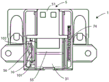
fig. 5 shows a rear perspective view of a door locking device according to the present invention in a configuration: in this configuration, the slide is in the retracted position;
fig. 6 shows a rear perspective view of the door locking device according to fig. 4 in the following configuration: in this configuration, the slider is in the extracted position;
FIG. 7 shows the door locking device of FIG. 6 in longitudinal cross-section;
fig. 8 shows a slide of the door locking device according to the invention in a partially cut-away perspective view;
figure 9 shows a longitudinal section of the door locking device according to the invention, in which the arrangement of the electronic control unit can be seen;
FIG. 10 illustrates the connection of the electrical connector;
figure 11 shows the connection of the electrical connectors to the various parts of the electrical circuit of the electronic control unit of the door locking device according to the invention;
figure 12 shows the means for moving the door locking device according to the invention in its coupling with the slider, in which the unlocking means assume a first configuration;
figure 13 shows the means for moving the door locking device according to the invention in its coupling with the slider, wherein the unlocking means assume a second configuration;
fig. 14 shows an emergency release system of the door locking device according to the present invention;
fig. 15 illustrates a partial sectional view of a washing machine to show an arrangement of a door locking device according to the present invention;
fig. 16 shows the door locking device in the following configuration: in this configuration, the slider is in the extracted position;
fig. 17 shows the door locking device in the following configuration: in this configuration, the slider is pushed to the retracted position;
fig. 18 shows the door locking device in a configuration in which the emergency release system returns to its initial position;
figure 19 shows how the water flow is distributed over the slider or intermediate protective element of the door locking device according to the invention;
FIG. 20 shows an exploded view of a second embodiment of a door locking device according to the present invention;
fig. 21 shows a perspective detail of the door locking device according to fig. 20 without the protective element and some movement transmission members;
FIG. 22 shows another perspective view of a detail of FIG. 21;
FIG. 23 shows a top view of the opened door locking device according to FIG. 20;
FIG. 24 shows a bottom perspective view of the control electronics of the door locking device according to FIG. 20;
figure 25 shows details of the control electronics of the door locking device according to figure 20;
FIG. 26 shows the circuitry of the control electronics of the door locking device according to FIG. 20;
FIG. 27 shows a top view of the door locking device opened in a first operating configuration;
FIG. 28 shows a top view of the open door locking device in a second operational configuration;
FIG. 29 shows a top view of the open door locking device in a third operational configuration; and
figure 30 shows a top view of the opened door locking device in a fourth operating configuration.
Detailed Description
Like parts will be designated by the same reference numerals in the various drawings.
With reference to fig. 1 and 2, a door locking device according to the invention is shown, indicated as a whole by the reference numeral 1.
The door locking device 1 mainly comprises a base 2, a protective element 3, an upper cover 4, a slide 5, an electronic control unit 6, a moving means 7 and an emergency unlocking system 8.
The base 2 has a first housing 21 and a second housing 22, the function of which will be better explained below.
Furthermore, the base 2 has a connector support 23, into which connector support 23 an electrical connector can be inserted.
Referring also to fig. 3, 4 and 5, it can be seen that the protective intermediate element 3 can be mechanically coupled to said base 2 by coupling means (for example screws or the like) or more preferably by interlocking, and that the protective intermediate element 3 is substantially hollow on the outside so as to be defined together with said base 2, said first shell 21 and said second shell 22.
The protective intermediate element 3, together with the cap 4, also defines a third housing 31 by means of two side walls 32, indicated respectively with 321 and 322, and an upper surface 33 of the protective intermediate element 3 itself. The opening 34 is again identified by means of the cover.
On the outer wall of the side wall 322, there are two windows 3221 and 3222 horizontally aligned.
On the side, the protective intermediate element 3 also has holes 35 for fixing screws (not shown in the figures), while between the upper surface 33 and the front surface opposite to the rear surface where the openings 34 are identified, a system of partitions 36 is provided. In particular, the baffle system 36 has: a pair of parallel partitions 361, said pair of parallel partitions 361 laterally bounding said upper surface 33; and a further partition 362, said further partition 362 extending along said front surface to delimit the front opening 37, the function of which will be better explained below. The parallel partition 361 and the further partition 362 are seamless.
Furthermore, the protective intermediate element 3 has a first recess 381 on one side and a second recess 382 on the opposite side.
In practice, the upper surface 33 is interposed between the first void 381 and the second void 382.
In addition, the first void 381 and the second void 382 are also bounded by the pair of partition plates 361. Laterally, the lateral receptacle 382 also has a slot 383.
The shielding intermediate element 3 further comprises a fixing tongue 39 for fixing the entire door-locking device 1 to a household appliance equipped with a door-locking device.
The cap 4 has a shape adapted to be arranged on the wall 32, the cap 4 covering the entire surface of said protective intermediate element 3 and having side edges adapted to be arranged outside said side walls 32.
Furthermore, as mentioned above, when the cap 4 is coupled to the protective intermediate element, the opening 34 is completed.
The base 2, the protective intermediate element 3 and the top cover 4 together form, when coupled, a protective shell I of the door locking device 1 according to the invention. The upper surface of said top cover 4 comprises a flat portion 41 and a steep portion 42, so that when said top cover 4 is placed on said protective intermediate element 3, said edges remain facing downwards and project with respect to the periphery of said protective intermediate element 3 itself, wherein said flat portion 41 has longitudinal reliefs 411 arranged parallel to each other, said longitudinal reliefs 411 being adapted to guide water that may fall on the cover 4.
The base 2 has a set of rectangular holes 24 on the convex bottom (as shown in fig. 2) of the housing 21 for accommodating the motor, the set of rectangular holes 24 having a function of discharging any water drops entering the base 2 of the door locking device as shown in fig. 4.
The slide 5 is slidably movable and interposed between the protective intermediate element 3 and the top cover 4, so that the slide 5 can pass through the window 34 in a retracted position (see fig. 5) and in an extracted position (see fig. 6 and 7).
Referring to fig. 8, the slider 5 has a locking portion 51 for being withdrawn through the opening 34 when the slider 5 is in the withdrawn position, and for interacting with a door of a washing machine or a home appliance to which the door locking device 1 is generally mounted.
The slider 5 further comprises: the rack 52, the rack 52 is inserted into the first void 381; and a longitudinal bar 53, the longitudinal bar 53 being provided with teeth 531, the longitudinal bar 53 being inserted in said lateral housing 382 and being able to slide in said lateral housing 382 and even being able to move through said slot 383. The locking portion 51 has a groove 511 in the shape of a "Y" at the top, and also two through holes 512 and 513, the through holes 512 and 513 being adapted to allow the outflow or passage of any water that may eventually fall on the locking portion 51.
Between said locking portion 51 and said rack 52 and between said locking portion 51 and said longitudinal bar 53, respectively, said slider 5 also has some ribs 54 for accommodating any possible water drops that may fall on the slider 5, as will be explained in detail below.
Finally, the slide 5 comprises, behind said locking portion 51, a flat drainage element 55, which flat drainage element 55 has a steep or slightly descending surface for the water to flow onto the upper surface 33 of said shield intermediate element 3.
In the assembly shown, the ribs 54 are located within parallel partitions 361 so that water falls on the upper surface 33.
The electronic control unit 6, visible in fig. 9, comprises, in the case in question, a printed circuit 61, which printed circuit 61 is arranged below said upper surface 33 of said containing intermediate device 3 so as to be protected, on which printed circuit the electric circuit for connecting the electronic components is shown, and also visible in fig. 10 and 11, the electronic control unit 6 comprises two microswitches 611 and 612, each of which is arranged in correspondence with a respective one of said side windows 3221 and 3222 of said side wall 322, so that said longitudinal rod 53 of said slider 5 can interfere with the microswitches 611 and 612 when said slider 5 is moved.
The electronic control unit 6 also comprises an electrical connector 62, which electrical connector 62 is connected and fixed to the printed circuit 61 and is intended to be inserted into the connector support 23 of the base 2. The connector 62 is intended to electrically and operatively connect the circuitry of the printed circuit 61 to the control logic of the household appliance (not shown in the figures) on which the door locking device 1 is installed.
The electronic control unit 6 also comprises a reed switch 63 (as known in the art) for checking the status of the closed door or the open door, and a PTC 64 for protecting the motor 71 that actuates the device.
When assembling the door locking device 1, the electrical connector 62 and the support 23 for the connector are placed in correspondence with said front opening 37, said front opening 37 being limited and protected by said further partition 362 as described against any dripping, as will be better explained below.
As can be seen from fig. 12 and 13, the moving device 7 includes: a motor 71, the motor 71 having a shaft 72 provided in the first housing 21 of the base 2; a pinion 73 keyed on said shaft 72; a gear 74, said gear 74 being arranged in said second housing 22 of said base 2, being engaged with said rack 52 of the slider 5 by means of a pinion 75 integral with this gear 74.
Said electronic control unit 6 and said moving means 7 constitute a system for moving and controlling the slide 5.
The emergency unlocking system 8 includes a lever 81 (see also fig. 14), the lever 81 having: a first portion 811, the free end of which 811 interferes with the tooth 531 of the longitudinal bar 53 of the slider 5; a second portion 812, the second portion 812 forming a "V" shape with the first portion 811; a pin 813, the pin 813 being disposed between the first portion 811 and the second portion 812 at a vertex of a "V" formed by the first portion 811 and the second portion 812.
The pin 813 pivots on the base 2.
Furthermore, said emergency unlocking system 8 also comprises a further longitudinal element 814, which further longitudinal element 814 is coupled at one end to said second portion 812 by a flexible elbow 815, which in the present embodiment is made of plastic. At the other end, the longitudinal element 814 comprises a release buoy 816, to which release buoy 816 a lanyard or any other traction member (not shown in the figures) may be coupled.
The emergency unlocking system 8 also comprises a helical spring 82 arranged on the pin 813, the helical spring 82 being able to keep the rod 81 in a predetermined position, as better described below.
The operation of the door locking device 1 described above is as follows.
More specifically, in order to better understand the operation of the door locking device 1, the functional operation and the protective operation are distinguished in terms of possible water droplets that may fall on the door locking device 1 itself.
In summary, reference is now additionally made to fig. 15, in which the installation of the door locking device 1 in the washing machine 9 is illustrated, wherein the body or frame 92 and the cover 91 are clearly distinguished. Of course, the slider 5 is configured to interfere with the cover 91 when it is in the extracted position, to keep it closed.
Regarding the functional operation, by means of a control logic (not shown in the figures) of the washing machine 9 connected to the electronic control unit 6 via the electrical connector 62, the motor 71 is allowed to be driven to rotate a gear 74 by means of a pinion 73 moved by a motor shaft 72, the gear 74 being in fact a reduction gear.
Thus, the pinion 75 engaged with the rack 52 of the slider 5 enables the slider 5 itself to pass from a retracted position, in which the locking portion 51 of the slider 5 is housed completely or partially inside the protective shell I, and said longitudinal rod 53 closes the microswitch 611 overlapping the corresponding window 3221, to an extracted position, in which the locking portion 51 of the slider 5 protrudes from said opening 34 and therefore from said protective shell I, and the longitudinal rod 53 moves accordingly, opening the microswitch 611 and closing the microswitch 612 physically overlapping the window 3222.
When the microswitch 611 and 612 combination is closed, the control logic unit of the washing machine 9 can electronically determine whether the door 91 is locked. The control unit of the washing machine detects whether the door 91 is closed by a signal transmitted from a reed switch 63 provided on the printed circuit 61, the reed switch 63 interfering with a magnet (not shown) placed on the door 91 in correspondence therewith in a closed state.
Thus, in the extracted position, the slider 5 interferes with the door 91 of the washing machine 9, locking the door 91 in position.
Besides, with reference to fig. 16, when the slider 5 is in the extracted position, the lever 81 is in an initial position in which the lever 81 is held by the coil spring 82 and in which the lever 81 does not interfere with the movement of the slider 5.
In case it is necessary to open the door 91 for emergency reasons during the washing cycle, the lanyard or any mechanical element (not shown in fig. 17) connected to the release float 816 needs to be pulled in the direction of arrow a.
In this way, thanks to the traction of the longitudinal element 814, by rotating the rod 81 according to the arrow B, thanks to the flexible elbow 815 it is obtained that the free end of the first portion 811 will engage the teeth 531 of the longitudinal rod 53, forcing the slider 5 from the extracted position to the retracted position.
The lanyard is then released and the lever 81 will return to its original position by rotating in the direction of arrow C, due to the action of the spring 82, as shown in figure 18.
However, as mentioned above, water often leaks from the drum, which often wets the door locking device and associated electrical components.
According to the door locking device 1 of the present invention, in the case where water falls on the upper surface of the top cover 4, the water is first guided through the longitudinal embossed portion 411 of the flat portion, which will not drop the water laterally, and can be turned toward the steep portion 42, thereby preventing the water from entering the door locking device 1.
If the slide 5 is in the extracted position, a part of the water may anyway fall on the surface of the slide 5, for example by seeping through the opening 34 in the door locking device 1.
However, in this case, a part of the water is collected by the grooves 511, which easily turn the water due to the "Y" shape at the side, thereby dropping the water. However, other parts of the water may be guided and drip through the two through holes 512 and 513 located approximately at the edge of the locking portion 51 in order to drain the water out of the body of the door locking device 1.
In the event that an excessive amount of water falls on the slider 5, when the slider 5 is in the extracted position, such that the grooves 511 of the locking portion 51 cannot collect water in their entirety and allow water to fall to the sides, the ribs 54 will tend to collect water on the flat drainage element 55, which in turn will concentrate the water on the upper surface 33 of said protective intermediate element 3, so that the water can flow through the partitions 361 and 362 without risk of dripping on the electronic components of the electronic control unit 6 or on the electrical connector 62, as shown in fig. 19, wherein the flow of water is indicated by the dashed arrows.
In particular, it can also be observed how the flat draining element 55 promotes the outflow of water from the surface of the locking portion 51 of the slider 5 onto the upper surface 33 of said shielding intermediate element 3.
Furthermore, if water still penetrates between the protective element 3 and the top cover 4, for example due to a particularly violent splash, in this case it still tends to be contained between the parallel partitions 361, so as to lie on the upper surface 33 of the protective intermediate element 3, and is then guided again by the partitions 361, bifurcating into two streams guided by the partitions 362, so as to prevent water and humidity from reaching the electronic control unit 6 and the connector 62.
Referring now to fig. 20 to 24, the structure of a second embodiment of the door locking device according to the present invention is observed.
In particular, similar parts will not be described again, and only modifications to the above-described first embodiment will be considered hereinafter.
In particular, it can be observed that the slide 5 comprises, in addition to the rack 52, a further rack 52', in correspondence of which, on a surface facing upwards in particular in this case, a constraint path 56 is obtained, this constraint path 56 having: a first seat 561; a second seat 562 opposite to the first seat 561; a third seat 563 arranged at the rear of said first seat 561 and a fourth seat 564 opposite said first seat 561 and parallel to said second seat 562. Furthermore, the door locking device 1 comprises a control member 10, which control member 10 has a first end 101 hinged on said guard element 3 and a second end 102 engaged or arranged to slide in said constraint path 56.
The slider 5 further comprises: a tooth 57, as better defined hereinafter, which tooth 57 cooperates with the switch 67 by opening the switch 67; a recess 57', which recess 57' does not actuate the switch 67, leaving it in the closed state; a raised portion 57 "located at the same height of the tooth 57, the raised portion 57" cooperating with the switch 67 by opening the switch 67. The function and effect of the signal generated by the interaction between the tooth loose piece 57 and the portions 57' and 57 "and the switch 67 will be better described below.
The door lock 1 of the second embodiment in question also has a return spring 58, which return spring 58 serves to return the slider 5 to the extracted position, as will be better explained below.
In this embodiment, the gear 74 of the moving means 7 has a shaft 741, to one end of which shaft 741 a further pinion 742 is connected, which pinion 742 is intended to engage with the further rack 52'.
The electronic control unit 6 (see fig. 24-26) is realized by a suitably cut-out moulded plastic support 65, in which the ramps and the metal connections 66 are provided.
The electronic control unit 6 further comprises a switch 67, the switch 67 having a release mechanism 671, which release mechanism 671 engages with the teeth 57 and portions 57 "of the sledge 5 when the sledge 5 is put in place, as will be described in detail below. The motor 71 of the moving unit tends to move the slider 5 into the retracted configuration under its active action (i.e. when energized), while the return spring 58 always tends to return the slider 5 to the extracted condition, contrary to the action of the motor. In particular, when said slider 5 is extracted, different signals are successively present due to the interaction of the tooth 57 and the portion 57 ″ with the release mechanism 671 of the switch 67, due to the opening and closing of the switch 67 by the release mechanism 671.
In some embodiments, the electronic control unit 6 may be implemented by means of a printed circuit (as in the first embodiment described above) or other system for implementing an electronic or microelectronic circuit.
Referring to fig. 26, the electrical diagram can be seen along with some of the major control connections between the motor 71, reed switch 63 and switch 67.
The second embodiment of the door lock 1 described above operates as follows.
The structure of the door locking device 1 according to the present embodiment is similar to that described with respect to the first embodiment. Therefore, the operation in the case where water drops fall thereon is completely similar to that of the first embodiment described above.
On the other hand, with regard to the functional operation of the door locking device 1, starting from the configuration of fig. 27, in fig. 27 the slider 5 is in the retracted position, the return spring 58 tends to draw the slider 5 out, the motor is closed, the switch 67 is open (because the release mechanism 671 interacts with the portion 57 "), and the control member 10 is in traction, in contrast to the reaction to the spring 58. When the motor 71 is activated by the household appliance control logic (not shown in the figures) in order to extract the slider 5, by rotating according to arrow a, the pinion 73 moves the gear 74, which in turn moves the further pinion 742, acting on the racks 52 and 52', thus bringing the second end 102 of the control member 10 from the first seat 561 to the second seat 562, as shown in fig. 28. In this step, the contact 67 is closed because the release mechanism 671 passes from the opposite part of the tooth 57 out of the part 57 ".
Subsequently, due to the interruption of the action of said motor 71, due to the timing effect after the slider 5 reaches the stop 3611 (or by closure of the reading switch 67, since the release mechanism 671 has moved outside the portion 57 ", opposite the tooth 57), following the action of the return spring 58, said second end 102 is constrained to position itself in said third seat 563, allowing said slider 5 to move from said retracted position to said extracted position, as shown in fig. 29. The position 563 in the direction of movement is not defined by the member 10, but its extension is based on the interaction of the slider 5 with the door of the household appliance that must be locked (not shown). Basically, the extension or travel of the slider 5 is limited (by defining the position 563 at which the end 102 of the member 10 on the slider 5 stops) by the fact that the free end of the slider 5 contacts the wall of the door of the household appliance to be locked.
At the same time, in this extracted position, the release mechanism 671 moves to the portion 57' without interference, closing the switch 67. In this way, the control logic of the household appliance can determine that the slider 5 is in the extracted position.
Subsequently, upon further actuation of the motor 71, which always rotates according to arrow a, the second end 102 of the control member 10 reaches the fourth seat 564 from the third seat 563, as shown in fig. 30, producing the same reporting of the position state of the slider 5, of the spring 58 and of the switch 67 in the state shown in fig. 28. In fact, the height of the end 102 in the direction of movement is the same while remaining on the other seat 564 of the constraint path with respect to the seat 562 of fig. 28.
Naturally, once the motor 71 stops its action, the return spring 58 moves the second end 102 from the fourth seat 564 to the first seat 561.
In this way, the slider 5 reaches the retracted position from the extracted position.
In this way, by rotating the motor 71 in only one direction of rotation, it is possible to move the slider 5 from the retracted position to the extracted position and vice versa, thus greatly simplifying its control.
The tooth 57 is in a particular abnormal operating condition, i.e. a condition resulting from some unauthorized use, the system is not activated without the household appliance door, so that the stroke of the slider 5 is not interrupted by contact with the free end of the slider 5 abutting against the household appliance door (which is not present in this abnormal condition). In other words, the slider 5 has an additional travel beyond the normal state of the locked door, wherein the release mechanism 671 is provided in correspondence with the portion 57'. In order to issue this additional travel signal, the tooth 57 intervenes, which tooth 57 interacts with the release mechanism 671 of the switch 67, issuing an additional travel signal, thus causing the household appliance to malfunction. The advantage of the door lock according to the invention is that it is particularly compact.
The present invention has been described for illustrative but not limitative purposes, according to its preferred embodiments, but it is to be understood that modifications and/or changes can be made by those skilled in the art without departing from the relevant scope as defined in the enclosed claims.

Claims (12)

1.门锁定装置(1),包括1. Door locking device (1), including 具有窗口(34)的防护壳(I),protective case (I) with window (34), 滑动件(5),所述滑动件包括用于与器物(9)的门(91)接合的锁定部分(51),其中,所述滑动件(5)被容纳在所述防护壳(I)中,并且其中所述滑动件(5)能够移动穿过所述窗口(34)而呈现缩回位置和抽出位置,在所述缩回位置,所述锁定部分(51)至少部分地被容纳在所述防护壳(I)中,在所述抽出位置,所述锁定部分(51)至少部分地被从所述防护壳(I)中抽出,以及A slider (5) comprising a locking portion (51) for engaging with a door (91) of an utensil (9), wherein the slider (5) is accommodated in the protective casing (I) and wherein the slide (5) is movable through the window (34) to assume a retracted position and an extracted position in which the locking portion (51) is at least partially received in in the protective casing (I), in the withdrawn position, the locking portion (51) is at least partially withdrawn from the protective casing (I), and 所述滑动件(5)的移动和控制系统(6、7),所述移动和控制系统构造成允许所述滑动件(5)从所述缩回位置移至所述抽出位置,以及从所述抽出位置移至所述缩回位置,Movement and control systems (6, 7) of the slider (5) configured to allow the slider (5) to move from the retracted position to the withdrawn position, and from all the withdrawn position is moved to the retracted position, 所述门锁定装置的特征在于,所述防护壳(I)包括The door locking device is characterized in that the protective casing (I) comprises 基座(2),base (2), 能够与所述基座(2)联接的防护中间元件(3),以及a protective intermediate element (3) capable of being coupled with said base (2), and 能够与所述防护中间元件(3)联接的顶盖(4),a top cover (4) capable of being coupled with said protective intermediate element (3), 其中,所述移动和控制系统(6、7)布置在所述基座(2)与所述防护中间元件(3)之间,以及wherein said movement and control system (6, 7) is arranged between said base (2) and said protective intermediate element (3), and 其中,所述滑动件(5)被设置在所述防护中间元件(3)与所述顶盖(4)之间。Wherein, the slider (5) is arranged between the protective intermediate element (3) and the top cover (4). 2.根据前一权利要求所述的门锁定装置(1),其特征在于,2. Door locking device (1) according to the preceding claim, characterized in that, 所述防护中间元件(3)包括:The protective intermediate element (3) includes: 上表面(33),upper surface (33), 布置在所述上表面(33)的侧向边缘处的一对平行的隔板(361),以及a pair of parallel baffles (361) arranged at the lateral edges of said upper surface (33), and 沿与定位有所述窗口(34)的侧向表面相反的侧向表面延伸的另外的隔板(362),所述另外的隔板被布置成围绕前开口(37)。A further baffle (362) extending along a lateral surface opposite the lateral surface on which the window (34) is located, the further baffle being arranged to surround the front opening (37). 3.根据前述权利要求中的任一项所述的门锁定装置(1),其特征在于,所述滑动件(5)包括侧向肋(54),以用于容纳可能落在所述锁定部分(51)上的水滴并将所述水滴排放到所述防护中间元件(3)的所述上表面(33)上。3. Door locking device (1) according to any one of the preceding claims, characterized in that the slide (5) comprises lateral ribs (54) for accommodating possible falls on the locking water droplets on the part (51) and discharge them onto the upper surface (33) of the protective intermediate element (3). 4.根据前一权利要求所述的门锁定装置(1),其特征在于,所述锁定部分(51)具有:位于顶部(511)的凹槽、和/或两个通孔(512、513),以允许排放当所述滑动件(5)处于所述抽出位置时可能落在所述锁定部分(51)上的水。4. Door locking device (1) according to the preceding claim, characterized in that the locking part (51) has a groove at the top (511), and/or two through holes (512, 513) ) to allow drainage of water that may fall on the locking portion (51) when the slider (5) is in the withdrawn position. 5.根据前述权利要求中的任一项所述的门锁定装置(1),其特征在于,所述滑动件(5)包括平坦的排水元件(55),所述平坦的排水元件布置在所述锁定部分(51)的后部,并且所述平坦的排水元件具有陡峭的或稍微倾斜的表面,以便将所述锁定部分(51)上的水排放到所述防护中间元件(3)的所述上表面(33)上。5. Door locking device (1) according to any one of the preceding claims, characterized in that the slide (5) comprises a flat drainage element (55) arranged in the the rear of the locking part (51), and the flat drainage element has a steep or slightly inclined surface in order to drain the water on the locking part (51) to all parts of the protective intermediate element (3). on the upper surface (33). 6.根据前述权利要求中的任一项所述的门锁定装置(1),其特征在于,所述移动和控制系统包括电子控制单元(6),所述电子控制单元又包括:6. Door locking device (1) according to any of the preceding claims, characterized in that the movement and control system comprises an electronic control unit (6) which in turn comprises: 布置在所述防护中间元件(3)的所述上表面(33)的下方的印刷电路板(61),以及a printed circuit board (61) arranged below said upper surface (33) of said protective intermediate element (3), and 用于与洗衣机(9)、器物等的逻辑控制单元连接的电连接器(62),其中所述电连接器(62)连接至并固定在所述印刷电路板(61)上,并且其中所述电连接器(62)布置在所述前开口(37)处;或者An electrical connector (62) for connection with a logic control unit of a washing machine (9), utensils, etc., wherein the electrical connector (62) is connected to and fixed on the printed circuit board (61), and wherein the the electrical connector (62) is arranged at the front opening (37); or 所述电子控制单元是由共同模制的塑料支撑件(65)制成的,在所述塑料支撑件内布置有轨道和金属连接部(66)。The electronic control unit is made of a co-molded plastic support (65) within which rails and metal connections (66) are arranged. 7.根据前述权利要求中的任一项所述的门锁定装置(1),其特征在于,7. Door locking device (1) according to any of the preceding claims, characterized in that, 所述基座(2)具有第一壳体(21)和第二壳体(22),The base (2) has a first casing (21) and a second casing (22), 所述滑动件包括齿条(52),以及The slider includes a rack (52), and 所述移动和控制系统包括移动器件(7),所述移动器件(7)又包括:The movement and control system includes a moving device (7), which further includes: 电动机(71),所述电动机布置在所述基座(2)的所述第一壳体(21)中,an electric motor (71) arranged in the first housing (21) of the base (2), 减速构件(73、74),所述减速构件布置在所述第二壳体(22)中,以用于将运动从所述电动机(71)传递到所述齿条(52),从而允许所述滑动件(5)从所述缩回位置移至所述抽出位置,以及从所述抽出位置移至所述缩回位置。reduction members (73, 74) arranged in the second housing (22) for transmitting motion from the electric motor (71) to the rack (52) allowing all The slider (5) is moved from the retracted position to the withdrawn position and from the withdrawn position to the withdrawn position. 8.根据前一权利要求所述的门锁定装置(1),其特征在于,所述减速构件包括:8. A door locking device (1) according to the preceding claim, characterized in that the deceleration member comprises: 小齿轮(73),所述小齿轮(73)键接至所述电动机(71)的轴(72),齿轮(74),所述齿轮(74)布置在所述基座(2)的所述第二壳体(22)中,与所述轴(72)的所述小齿轮(73)接合,A pinion (73) keyed to the shaft (72) of the electric motor (71), a gear (74) arranged in all parts of the base (2) In the second housing (22), engaging with the pinion (73) of the shaft (72), 与所述齿轮(74)同轴的另外的小齿轮(75),所述另外的小齿轮(75)与所述滑动件(5)的所述齿条(52)接合。A further pinion (75) coaxial with said gear (74), said further pinion (75) engages with said rack (52) of said slide (5). 9.根据权利要求7至8中的任一项所述的门锁定装置(1),其特征在于,9. A door locking device (1) according to any one of claims 7 to 8, characterized in that, 所述移动器件(7)包括与所述齿轮(74)同轴的另外的小齿轮(742),以及said moving means (7) comprise a further pinion (742) coaxial with said gear (74), and 所述滑动件(5)包括与所述另外的小齿轮(742)接合的另外的齿条(52')。The slider (5) includes a further rack (52') that engages with the further pinion (742). 10.根据权利要求7至9中的任一项所述的门锁定装置(1),其特征在于,10. A door locking device (1) according to any one of claims 7 to 9, characterized in that, 所述滑动件(5)具有约束路径(56),The slider (5) has a constraining path (56), 所述门锁定装置包括:The door locking device includes: 控制构件(10),所述控制构件具有第一端部(101)以及第二端部(102),所述第一端部(101)在所述防护中间元件(3)上枢转,所述第二端部(102)接合成在上述约束路径(56)内滑动,以及A control member (10) having a first end (101) and a second end (102), the first end (101) pivoting on the guard intermediate element (3), so that said second end (102) is engaged to slide within said restraint path (56), and 复位弹簧(58),所述复位弹簧(58)用于将所述滑动件(5)复位就位,a return spring (58) for returning the slider (5) into place, 其中,所述约束路径(56)和所述复位弹簧(58)的布置构造成允许通过致动所述电动机(71)使所述电动机(71)仅沿一个方向旋转而使所述滑动件(5)从所述缩回位置移至所述抽出位置,以及从所述抽出位置移至所述缩回位置。wherein said restraint path (56) and said return spring (58) are arranged so as to allow said slider (71) to rotate in only one direction by actuating said motor (71) 5) Moving from the retracted position to the retracted position, and from the retracted position to the retracted position. 11.根据权利要求10所述的门锁定装置(1),其特征在于,所述约束路径具有:第一座部(561);与所述第一座部(561)相对的第二座部(562);第三座部(563),所述第三座部(563)布置在所述第一座部(561)的后面;以及第四座部(564),所述第四座部(564)与所述第一座部(561)相对并且平行于所述第二座部(562)。11. The door locking device (1) according to claim 10, wherein the restraint path has: a first seat portion (561); a second seat portion opposite to the first seat portion (561) (562); a third seat (563) arranged behind the first seat (561); and a fourth seat (564), the fourth seat (564) is opposite to the first seat (561) and parallel to the second seat (562). 12.根据前述权利要求中的任一项所述的门锁定装置(1),其特征在于,所述顶盖(4)包括平坦部分(41)和陡峭部分(42),所述平坦部分(41)具有布置成彼此平行的纵向浮凸部(411),所述纵向浮凸部(411)适于引导可能落在所述纵向浮凸部上的水,所述陡峭部分(42)具有面向下的边缘。12. Door locking device (1) according to any of the preceding claims, characterized in that the top cover (4) comprises a flat part (41) and a steep part (42), the flat part (41) 41) Having longitudinal embossments (411) arranged parallel to each other, said longitudinal embossments (411) being adapted to guide water that may fall on said longitudinal embossments, said steep portion (42) having facing lower edge.
CN202011098692.XA 2019-10-15 2020-10-14 Improved door locking mechanism Pending CN112663290A (en)

Applications Claiming Priority (2)

Application Number Priority Date Filing Date Title
IT102019000018812 2019-10-15
IT201900018812 2019-10-15

Publications (1)

Publication Number Publication Date
CN112663290A true CN112663290A (en) 2021-04-16

Family

ID=69743718

Family Applications (1)

Application Number Title Priority Date Filing Date
CN202011098692.XA Pending CN112663290A (en) 2019-10-15 2020-10-14 Improved door locking mechanism

Country Status (4)

Country Link
US (1) US12168887B2 (en)
EP (1) EP3808888B1 (en)
KR (1) KR102780733B1 (en)
CN (1) CN112663290A (en)

Families Citing this family (2)

* Cited by examiner, † Cited by third party
Publication number Priority date Publication date Assignee Title
IT201800002107A1 (en) * 2018-01-29 2019-07-29 Illinois Tool Works MOTORIZED LOCK SWITCH MODULE FOR A DOOR LOCK FOR HOUSEHOLD APPLIANCES
TR202005084A2 (en) * 2020-03-31 2021-10-21 Serdar Plastik Sanayi Ve Ticaret Anonim Sirketi Self-Resetting Lock Mechanism

Citations (8)

* Cited by examiner, † Cited by third party
Publication number Priority date Publication date Assignee Title
CN2837339Y (en) * 2005-07-18 2006-11-15 温州天健电器有限公司 A kind of locking device of barrel washing machine door
CN101892571B (en) * 2009-05-19 2012-04-25 温州天健电器有限公司 Locking device of door of washing machine
KR20120004174U (en) * 2010-10-04 2012-06-13 경수 예 Lid lock s/w
CN203741614U (en) * 2014-01-02 2014-07-30 合肥荣事达三洋电器股份有限公司 Automatic door lock device
CN106522698A (en) * 2016-12-27 2017-03-22 皓月汽车安全系统技术股份有限公司 Integral front door lock body assembly
CN206503004U (en) * 2017-02-21 2017-09-19 神龙电气有限公司 Proof mechanism of water in washing machine door switch
KR101855470B1 (en) * 2017-09-08 2018-07-05 한국중천전화산업 주식회사 Heart Cam Type Washer Door Locker
CN109469415A (en) * 2018-11-27 2019-03-15 金华市宏昌电器有限公司 A door lock switch for household appliances

Family Cites Families (8)

* Cited by examiner, † Cited by third party
Publication number Priority date Publication date Assignee Title
US4413592A (en) * 1982-09-29 1983-11-08 Jones George D Water damage preventer pan
US5437303A (en) * 1992-05-29 1995-08-01 Johnson; Addison M. Apparatus for containing fluid leaks and overflows from appliances
KR100820739B1 (en) * 2007-01-04 2008-04-11 삼성전자주식회사 washer
JP5537163B2 (en) * 2010-01-08 2014-07-02 日本電産サンキョー株式会社 Lid lock device
KR101606725B1 (en) * 2012-07-23 2016-03-28 엘지전자 주식회사 Lid locker of washing machine
CN205223654U (en) * 2014-11-25 2016-05-11 伊利诺斯工具制品有限公司 Lock and upper cover formula washing machine
KR101877043B1 (en) * 2016-11-29 2018-07-10 한국중천전화산업 주식회사 Washer Door Double Lock with Lid Lock Switch
EP3956515A1 (en) * 2019-04-19 2022-02-23 Elettrotecnica Rold S.R.L. Device for opening and closing a door, in particular a door for a household appliance for treating laundry

Patent Citations (8)

* Cited by examiner, † Cited by third party
Publication number Priority date Publication date Assignee Title
CN2837339Y (en) * 2005-07-18 2006-11-15 温州天健电器有限公司 A kind of locking device of barrel washing machine door
CN101892571B (en) * 2009-05-19 2012-04-25 温州天健电器有限公司 Locking device of door of washing machine
KR20120004174U (en) * 2010-10-04 2012-06-13 경수 예 Lid lock s/w
CN203741614U (en) * 2014-01-02 2014-07-30 合肥荣事达三洋电器股份有限公司 Automatic door lock device
CN106522698A (en) * 2016-12-27 2017-03-22 皓月汽车安全系统技术股份有限公司 Integral front door lock body assembly
CN206503004U (en) * 2017-02-21 2017-09-19 神龙电气有限公司 Proof mechanism of water in washing machine door switch
KR101855470B1 (en) * 2017-09-08 2018-07-05 한국중천전화산업 주식회사 Heart Cam Type Washer Door Locker
CN109469415A (en) * 2018-11-27 2019-03-15 金华市宏昌电器有限公司 A door lock switch for household appliances

Also Published As

Publication number Publication date
EP3808888B1 (en) 2023-11-22
US12168887B2 (en) 2024-12-17
KR20210045323A (en) 2021-04-26
EP3808888C0 (en) 2023-11-22
US20210115702A1 (en) 2021-04-22
EP3808888A1 (en) 2021-04-21
KR102780733B1 (en) 2025-03-12

Similar Documents

Publication Publication Date Title
KR100748457B1 (en) Door lock device of home appliance
CN101163437B (en) Closing mechanisms for household appliances
KR101606725B1 (en) Lid locker of washing machine
US20140175809A1 (en) Closure mechanism for vehicle door
EP3091153B1 (en) Locking device for a door of a domestic appliance
EP2909405B1 (en) Door-lock device
CN112663290A (en) Improved door locking mechanism
EP1450661B1 (en) Dispenser device particularly for dishwashing machines
WO2016199056A1 (en) System to control the closing of a door of a household appliance, in particular for a washing machine, such as a dishwasher
CN110984703B (en) Induction type door lock
CN107761314B (en) Washing machine door lock
CN216893976U (en) Actuating mechanism with automatic door opening and closing function
KR102775232B1 (en) Dishwashing machine and control method of the same
WO2009061628A1 (en) Appliance latch with compact form factor
CN223840426U (en) Cooking body and microwave cooking appliance
KR102834967B1 (en) A push type auto-open door-lock equipment
CN112998517B (en) Cooking utensil
CN223256641U (en) Door lock device and electric appliance
KR102834965B1 (en) An auto-open door-lock equipment
KR102358167B1 (en) Washer door locker with water pass through device
CN222772040U (en) A mechanism for detecting door lock switch state and door lock for household appliances
CN214141616U (en) A core changing assembly and a water purifier
KR102757858B1 (en) Dishwashing machine
CN121285673A (en) Door lock device for household electrical appliance
CN112357985A (en) Trade core subassembly and purifier

Legal Events

Date Code Title Description
PB01 Publication
PB01 Publication
SE01 Entry into force of request for substantive examination
WD01 Invention patent application deemed withdrawn after publication

Application publication date: 20210416