The purpose of this invention is to provide configuration structure again and again, it can be at two or more, conversion fast between more several configurations.Another object of the present invention provides one and is optimized to the device that is suitable for combine digital computing usefulness predetermined function especially.Another purpose is before adding power supply, to provide to comprise to be suitable for disposing the device that it becomes one or more guiding initial configuration of intended purpose.Further purpose is to make one and is equipped with for transmitting the data purpose of device between the continuous configuration of (substantially) device.Another purpose is during cell configuration, guarantees to keep safely data, and makes the switching current minimum.Further purpose is to provide a configuration cache, and it allows to upgrade current no config memory.Another object of the present invention is to make device can select the configuration of himself from the exterior arrangement data source.
Another purpose is by partial logic is connected into the needed quantity that is configured to reduce programmable interconnect with line in advance.
Further purpose is by in advance the Elementary Function of appointment being arranged into the zone of device appointment, being that pre-line connects substantially in order to do making these Elementary Functions, thereby improving the performance of device again.
Therefore, one aspect of the present invention provides a kind of configurable SIC (semiconductor integrated circuit), be formed with a plurality of unit in its surface, has a kind of function on each unit at least, and at least with some other described cell interconnection, at least some unit have the interconnection that electricity can be selected its conduction state in a plurality of unit, in a plurality of unit at least other unit then have the interconnection that pre-line connects, each unit has two or more possible configurations, every kind of configuration is limited by the interconnection between Elementary Function and/or itself and other unit according to unit configuration data, and this circuit further comprises to be deposited at least two kinds of configuration of cells (each unit) and make one of possible configuration of cells become possible device with the device of configuration data with according to selected unit configuration data.
Interconnection as for pre-line connects is intended to can not interrupt its conduction state.The selection that the most handy code translator of configuration data comes control module function and/or cell interconnection is perhaps directly controlled by storer.Like this, for instance, unit configuration data decision signal is by the route of unit.Between config memory, code translator and selectable functions and interconnection, exist direct connecting path.Term as used herein " function " can be logic function, algorithm function and interconnect function.A unit can have one or more this functions, the perhaps combination of two or more these class functions.Configuration data memory preferably is placed in the unit.Select desired configuration with instruction bus from sequencer and controller received signal.One or more configurations can be connected (also being non-programmable) with line in advance.Utilize data transmission bus to programme to one or more configuration data memories easily.To more than one storer is programmable place, then provides an instruction to upgrade bus, with permission needed config memory is write.Upgrade bus with instruction and can upgrade current not accessed config memory with control interconnection and/or Elementary Function.
Because the present invention is especially relevant with dedicated devices, and this dedicated devices is optimized to the limited task of quantity performed at full speed that is suitable for, but it can dispose (when needing) apace again term of execution of program, to finish some other particular task, so, the unit is optimized Elementary Function according to initial configuration.Initial-configuration data is connected with line easily in advance.The initial configuration that should have two kinds of alternative pre-lines.Can be with the unit and in most of the cases unit optimization is become to be suitable for different Elementary Functions.It is useful that the interconnection even of pre-line is used with optimized function.
A kind of possible Elementary Function is the function of totalizer.Another aspect of the present invention provides many bit adder of addition bit words more than at least two, it comprises addition low level another many bit adder piece at least with piece of bit adder more than first and the high-order usefulness of addition, and have and selecting arrangement, wherein said another many bit adder piece from last carry that equals " 0 " and " 1 " calculate respectively two kinds possible and the result, in it and selecting arrangement then according to last carry select another many bit adder piece and.
In the digital signal processor application facet, will become arithmetic logic unit (ALU) to some unit optimization, and can be optimized to other unit the function of execution such as command decoder or processor register one class.The quantity of different units only is limited by the size of cell array.In practice, will be divided into many to array to realizing the effective especially isolated area of major function separately.Obviously, the configuration that each unit in these unit all has according to other realizes another kind of function, and the ability of other function in the certain limit often.These extra functions are controlled by controller and sequencer, and its role is to guarantee work as need be effective to correct function.Elementary Function can be used general interconnect resource, but the high speed between other unit Elementary Function connected its oneself private resource is arranged preferably.Like this, the performance of device does not also rely on general programmable interconnect resource, and by connect Elementary Function through resource to less parasitic load, can make the device computing faster.
For the safety of protected data when standing to change between configuration, each unit all has a latch by the control of function control bit.When between the configuration when advancing to change by each unit in standby impact damper reduce transient current, as for impact damper controllable be to be the state during disposing again with control line.
Obviously, although this device is special-purpose counting in the field of tool such as DSP one class, can select Elementary Function to adapt to the application of others.Therefore, present technique goes for any purposes.For example, another kind of purposes is as programmable communication device.
The method that another aspect of the present invention also provides a pair of configurable SIC (semiconductor integrated circuit) to be configured wherein, is programmed to sequence with data, so that select to become easy from have two kinds of possible required configurations at least.Usually, each unit in a plurality of unit has at least two kinds of configuration possibilities.Its advantage is that this configuration is programmable, and this method further comprises input and store configuration data.Further favourable characteristics are to programme to sequence, so that write before configuration data stored on circuit run duration official hour point.One aspect of the present invention provides a kind of SIC (semiconductor integrated circuit), and wherein circuit arrangement is in the sequence change of device run duration according to pre-programmed.
Only with example the present invention is described now with reference to accompanying drawing, wherein:
Below being that content and the particular content by digital signal processor (DSP) are that example is described the present invention as the integrated circuit of dedicated devices.According to the present invention, the structure that device is not limited to fix, and have re-configurable hardware so that allow that device (as DSP) is independently worked to every and be optimized.Therefore, on macroscopic view, device can be optimized to and be suitable for new purposes, MPEG for example, polygon tool (Polygon Engine), Blit-ter, DMA instrument etc., and on microcosmic, device can be optimized each operational code, for example multiplex arithmetric device, special multiplier etc.Like this, a kind of re-configurable specially again device (for example DSP) allow to replace many dedicated devices and only use chip piece.The operational code of optimizing improves performance.In fact, device can be changed between DSP, RISC or application specific processor with clock speed.
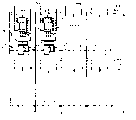
At first, demonstrate a re-configurable dedicated digital signal processor here referring to Fig. 1.Chip comprises inner core cellular zone 1, subregion static random-access memory (SRAM) 3, the sequencer with control line 7, clock 9 and clock line 11 and controller 5, and I/O end 13 able to programme and relevant data bus 15.Signal back-pressure contract code translator 17, order wire 19 and relevant I/O and Extended Capabilities Port 21 and address bus 23 also are shown among the figure.
A plurality of interior core units 2 are arranged, and they provide, for example (under the situation of DSP configuration) command decoder, register, program counter and stack pointer device etc.Can programme to finish some functions in each heart unit, core unit then is optimized to and is suitable for realizing specific function in some.Therefore, for example, referring to Fig. 4, this figure illustrates the optimization situation of some unit to some functions, i.e. ALU 2a, register 2b, program counter 2c, universal counter 2d, command decoder 2e and I/O end 2f.
Fig. 7 illustrates the synoptic diagram of the inner core configuration of cells that a with dashed lines marks, in interior core unit, comprise the have optional function logical block 22 of (for example 4 kinds), with 25 represent able to programme in core unit input ends (8) (also being electric optional interconnection) link two 4: 1 input multiplexers 26,28.Unit output is represented with 27.Further described the example of logical block configuration with reference to Figure 11,12,13 and 14.Input multiplexer is controlled respectively by 2-4 code translators 30,32.4-1 multiplexer in another 2-4 code translator, 34 steering logic unit 22, output multiplexer 70 are then by 48 controls of 2-4 code translators.Logical block directly connected in advance by symbol YA-YD represent.
As shown in Figure 7, the unit comprises the configurable memory device, and it includes configuration cache 36, instruction cache 38 and so-called " hard winding displacement " or fixing inking device 40.For the application of DSP aspect, fixing configuration comprises the initial DSP boot configuration and second configuration, for example multiplier arrangement of being made up of 3 * 2 bit configuration element 40a of being made up of 3 * 2 bit configuration element 40b.This is to be used for making initial (fixing) configuration can automatically realize the guiding of device, so that allow it have its initial special function.
In an illustrated embodiment, configuration cache 36 comprises 43 * 2 Bit data storer 36a-d, and it can upgrade bus 44 by instruction and write permission, and writes data from data bus 46.Instruction cache 38 comprises 8 * 2 Bit data storeies, and it can upgrade bus 44 by instruction and write permission, and writes data from data bus 46.Instruction hypervelocity buffer-stored 38 is read permission by Instruction Selection bus 42.Instruction Selection bus 42 allows 2-4 code translators 48 to select and allow to read among 4 data storer 36a-d one according to the data-carrier store on the instruction cache of selecting.The output of code translator 48 also makes things convenient for the direct configuration of logical block by control output in 4: 1 multiplexer 70.Fig. 7 also illustrates function control bit 50, and it allows read and write line (42,44) to be connected on the logical block 22.Function control bit 50 control lock storages 54 (see figure 10)s.
Figure 16 illustrates fixed configurations device 40 and configuration cache 36 ' is read 42, write 44 ' and data 46 ' annexation.Both only be cache 36 outfits to note among the figure read and write.
Get back to Fig. 2 and Fig. 3, piece 2 ', 2 " and the every configurations of representing inner core 2 of 2 .Bigger functional block as a string row access that is configured into.Each new configuration receives data from being elected to be locking inter-process line 52 of critical data and the unit 54 of last use.Other unit 54 is designated as inputing or outputing.Pei Zhi time can be the order of magnitude of 10 nanoseconds again.Core arrangement is optimized to each operational code of realization.This can make the word length of each arithmetic function regulate as required.Therefore, referring to Fig. 3,16 bit multiplication and COS functions are carried out in first inner core configuration (operational code 1), and 32 * 32 bit multiplication function are carried out in second inner core configuration (operational code 2), and 64 bit addition functions are then carried out in the 3rd configuration (operational code 3).
Referring now to Figure 10,, its explanation can be applicable to unit like the unit class shown in Figure 7 on output state control, and the units corresponding parts are illustrated with suitable reference number, exception be cache 38.
Mention as top, some unit is designated to be used to lock critical data, and therefore, this unit has from the latch means 54 of function control bit 50 inputs and keeps incoming line 56.The effect of these devices is to preserve the data mode of unit between configuration.In addition, be equipped with an impact damper 60, by its output state is set in known conditions transient current reduced when changing between disposing with box lunch.
Come the interconnect resource of description unit referring now to Fig. 8 a, 8b, 9a and 9b.How Fig. 8 a and 8b illustrate the unit with comprising that the piece that is optimized to different function units is arranged to normal piece (for example row and column) together.Fig. 8 b illustrates the row of ACC unit, ALU unit and shift unit and the row of two decoding units like this.Each cell columns has two overall situations (Y) bus (Y1, Y2, Y3, Y4 ... YN1, YN) each cell row has two overall situations (X) bus (X1, X2 at least ... X
N-1, X
n).Decoding unit is positioned at the top of every row piece, and three X buses are arranged.Be provided with bus switch BS in the Y bus between adjacent block.In addition, implicit expression (the perhaps direct connection of pre-winding displacement) Y bus YA-YD is arranged.These elements all unit below decoding unit runs to row always.In addition, local direct-connected path preferably is set between the unit.Like this, for the example of Fig. 8 b cell S C, its input links to each other with the output of last adjacent cells, following adjacent cells, right adjacent cells, left adjacent cells and next left adjacent cells.These connections are represented with U, D, R, L, J respectively.Be not that all cell variations all must be carried out all part connections.As for these locally-attached great majority, their conduction state is that electricity is optional, but in most cases, the adjacent connection on the left side will be the connection that pre-line connects.
How how Fig. 9 a just control the selection of output from the selection of the total line traffic control input of X and Y to the next column of identical X bus and Y bus with output multiplexer 70 as a cell descriptions input multiplexer 26 of core unit in all.
Arrangements of cells is become 10 * 8 pieces, and Fig. 9 c then illustrates the example of such array of cell block.Piece 100 is formed with 8 * 4 arrays, and I/O 102 able to programme, data bus and switch 104 and subregion SRAM106 also are shown among the figure.Each piece 100 comprises one 10 * 8 cellular arraies, and for simplicity, the row of unit have similar initial configuration in the piece.For example, Fig. 9 d illustrated block 100, it has 2 row 100a and b of unit, be configured to multiplexer module, row 100c is configured to the MAD musical instruments used in a Buddhist or Taoist mass, row 100d, be configured to the barrel shifter unit, row 100e is configured to arithmetic and logic unit, row 100f, be configured to accumulator element, row 100g and h then are configured to multiple multiplexer expanding element.The top of the row in every is decoding unit.
Referring now to Figure 15,, configurable static RAM (SRAM) 3 is deposited through its partition data from sequencer and controller 5 along partition data part 72.Data be deposited and be kept to the running of DSP need, is equipped with SRAM and then guarantees the visit of institute's store data is placed on the fast of outside than SRAM on device.
The running of sequencer and controller 5 control buss 42,44,45 and 46.Therefore, sequencer and controller 5 comprise the control to following operation: the independent data storer of selected cell, data are delivered to the realization sequential that configuration data in the unit is left in this storer and control in.External source (not shown) by storer provides the necessary control instruction to sequencer and controller 5.Except aforesaid operations, controller 5 can select the current independently data-carrier store that is not used so that can upgrade them with new configuration by external memory storage.
Figure 11, Figure 12 and 13 illustrate the variant of ALU, ACC and decoding unit respectively.Used among the figure and the reference number that adapts previously.
Figure 13 illustrates the unit example that code translator is optimized.Shown in Fig. 8 a and 8b, two decoding units are arranged above cell block.Illustrated variant is have pre-line interconnection YA, YB even a kind of, and they are fed to each following unit downwards.Other code translator will produce the interconnection that the pre-line of YC, YD connects.Like this, the ALU type unit of Figure 11 has connection YA, the YB that has pre-line to connect, and ACC type unit then has connection YA, YB, YC, the YD of pre-line.It shall yet further be noted that for ALU and ACC variant the adjacent connection in the left side is that pre-line connects, and for the ALU unit, then Cin, Cout are the interconnection that pre-line connects, and on the length direction of cell columns, move.Other X and Y bus are then as described above.
From the control signal of code translator output and will be with the Elementary Function of optimizing, also promptly special-purpose is considered to essential any function and carries out pre-line and connect the input of cell variations.
Figure 14 illustrates some different functions, and they can derive from ACC and the interior core unit of ALU of Figure 10 and Figure 11 respectively.
Figure 17 illustrates the another kind selection that DSP unit (diagram simply) internal element is arranged, its unit input and output only illustrate with 25 and 27 respectively.Storer comprises 8 * 3 Bit data storeies, and is equipped with 3-8 code translators 80, in order to do one that can choose in 8 options (for example: function or interconnection) that are included in the logical block.In order to upgrade data-carrier store specific in the discrete cell, the spy is equipped with storer selector switch 45 (being omitted in the arrangements of cells diagram of describing in front), therefore, can select needed unit, and select to write the specific data storages device that allows or read to allow with instruction renewal bus (44) or instruction bus (42).Data are written in the data-carrier store from memory data bus 46 (not illustrating Figure 17).
The novel adder structure that can constitute with this cell configuration is described referring now to Figure 18-21.Figure 18 illustrates one 16 bit adder, and represents with numeral 60 usually.Totalizer comprises a plurality of carries and selects totalizer 62, forms piece 64 of bit adder more than first and the piece of bit adder more than second 66.Totalizer 60 is two a1, a2, a3 ... a16 and b1, b2, b3 ... the 16 bit words additions that b16 represents are so that draw by S1, S2, S3 ... that S16 represents and, and carry bit " Cout ".
The piece of bit adder more than first 64 is the least-significant byte addition in each 16 bit words, and each has a carry that is associated to select totalizer 62.Each carry selects that totalizer comprises that two input end An, Bn (wherein n is a figure place), output terminal 68, carry go into 70, carry goes out 72 and first and second 2: 1 multiplexers 74,76.First input of first multiplexer 74 is equal to the value of An+Bn, and the hypothesis carry goes into to be " 0 ", and second input supposes that then carry goes into to be " 1 ".Go into 70 by carry and select output Sn.
Two inputs of second multiplexer 76 be equal to by An and Bn sum produce carry, its carry is gone into for being equal to ' 0 ' and ' 1 '.Going into 70 by carry selects carry to go out 72.Obviously, first carry selects the carry of totalizer to go into to equal " 0 ".
The piece of bit adder more than second 66 is the most-significant byte addition of each 16 word, and every has two relevant carries to select totalizer 78,80.Each carry selects totalizer 78,80 to constitute by above-mentioned similar methods.It is two 8 bit words a9-a10 that carry is selected totalizer 78 ... a16 and b9-b10 ... the b16 addition, and the carry of hypothesis first adder piece 64 to go out be 1, carry selects totalizer 80 to suppose that then carry goes out to be " 0 ".Therefore, calculate two outputs, and they are fed in the multiplexer 82 that is associated for each.Come out to select the output S that provides by the carry of first adder piece 64
n
In when operation, the first adder piece calculates the additive value of least-significant byte, and produces a carry and go out value.Simultaneously, the second adder piece calculate two kinds of the most-significant byte addition may with, and by the carry that adder block 64 produces go out to select correct and.Thereby the time delay (8ADD) that the time delay of 16 additions of calculating equals first 8 additions adds the time delay of selecting last 8 sums, also is the time delay (Max) of a multiplexer.
For each extra position adder block, its time delay equals the time delay of a multiplexer.For example, 32 time-delays that totalizer will produce 8ADD+3XMUX.Thereby compare with traditional adder structure, described adder structure causes the improvement of arithmetic speed.
Figure 20 illustrates another alternative cellular construction, and wherein, single dispensing unit just can replace the carry of two unit of two needs to select totalizer.
Figure 21 illustrates the traditional circuit of single-stage selection totalizer, and it can be used for replacing the circuit of Figure 19.
The running of outlines device now at first as mentioned above, is carried out " hard winding displacement " with hardware to inking device 40, perhaps fixes with DSP configuration 40a and multiplier arrangement 40b.
External memory storage (not shown) includes the configuration data of whole necessity, in order to control controller and sequencer, in order to do each data-carrier store (36a-d, 38) in each unit all can be programmed.For the data storer is programmed, typical process will be: at first by storer selector switch 45 selected cells, upgrade bus 44 by instruction and select to allow the data-carrier store that writes, and write data in the selected storer by data bus 46.
In four data storeies of configuration cache 36 each all includes enough configuration datas to select the input of logical block 22, also selects to be included in a kind of function in the logical block.
According to key instruction, the initial pilot operationp of device produces a kind of configuration among two kinds of initial configuration 40a, 40b.Like this, for example, DSP or multiplier arrangement have been set up.
Yet, if require device to realize another kind of function, division function for example, controller and sequencer 5 select also to allow to be written as the configuration cache 36 desired data-carrier stores of realizing necessary each unit of this kind configuration.External memory storage provides data necessary with selected cell and data-carrier store, realizes desired configuration.
Also have a kind of possibility, adopt other configuration of having programmed of self-configuring cache, write and replace other configuration.
Like this, for the example that provides, 4 kinds of possible configurations of configuration cache may be inadequate.Can software programming realize another kind of configuration.Programmer can determine how can to realize desired function/configuration (for example, can list many possible structural changes, perhaps represent with loading instruction) with reference to the technical specification of device.Although therefore loading instruction 1-4 can represent to be stored in most typical configuration in the configuration cache, programmer can determine for example to require loading instruction 33 from technical specification.Like this, programmer will be encased in instruction in the configuration cache.Such example will be arranged, and the there needs more configuration to handle the input data, can leave it in the cell memory in then to conduct interviews with clock speed.Yet this difficulty can be programmed by dispose cache with the configuration data of " additionally " to " redundancy " before this requirement again, configuration-direct again is included in the software program overcome.Sequencer can clock speed be controlled configuration again, comes the data of self-configuring then keeping safely in latch units.4 kinds of configurations of cache (36a-36d) can be at different cell positions by being used once more with different combinations.Instruction cache (38) becomes easily this, and this can select different local unit configurations from the global command on being arranged in instruction bus 42.