CN112602004B - Projector-combiner display with beam replication - Google Patents
Projector-combiner display with beam replication Download PDFInfo
- Publication number
- CN112602004B CN112602004B CN201880096871.4A CN201880096871A CN112602004B CN 112602004 B CN112602004 B CN 112602004B CN 201880096871 A CN201880096871 A CN 201880096871A CN 112602004 B CN112602004 B CN 112602004B
- Authority
- CN
- China
- Prior art keywords
- light
- image
- eye display
- waveguide
- beams
- Prior art date
- Legal status (The legal status is an assumption and is not a legal conclusion. Google has not performed a legal analysis and makes no representation as to the accuracy of the status listed.)
- Expired - Fee Related
Links
Images


Classifications
-
- G—PHYSICS
- G02—OPTICS
- G02B—OPTICAL ELEMENTS, SYSTEMS OR APPARATUS
- G02B27/00—Optical systems or apparatus not provided for by any of the groups G02B1/00 - G02B26/00, G02B30/00
- G02B27/01—Head-up displays
- G02B27/017—Head mounted
- G02B27/0172—Head mounted characterised by optical features
-
- G—PHYSICS
- G02—OPTICS
- G02B—OPTICAL ELEMENTS, SYSTEMS OR APPARATUS
- G02B27/00—Optical systems or apparatus not provided for by any of the groups G02B1/00 - G02B26/00, G02B30/00
- G02B27/0081—Optical systems or apparatus not provided for by any of the groups G02B1/00 - G02B26/00, G02B30/00 with means for altering, e.g. enlarging, the entrance or exit pupil
-
- G—PHYSICS
- G02—OPTICS
- G02B—OPTICAL ELEMENTS, SYSTEMS OR APPARATUS
- G02B27/00—Optical systems or apparatus not provided for by any of the groups G02B1/00 - G02B26/00, G02B30/00
- G02B27/10—Beam splitting or combining systems
- G02B27/106—Beam splitting or combining systems for splitting or combining a plurality of identical beams or images, e.g. image replication
-
- G—PHYSICS
- G02—OPTICS
- G02B—OPTICAL ELEMENTS, SYSTEMS OR APPARATUS
- G02B27/00—Optical systems or apparatus not provided for by any of the groups G02B1/00 - G02B26/00, G02B30/00
- G02B27/28—Optical systems or apparatus not provided for by any of the groups G02B1/00 - G02B26/00, G02B30/00 for polarising
- G02B27/283—Optical systems or apparatus not provided for by any of the groups G02B1/00 - G02B26/00, G02B30/00 for polarising used for beam splitting or combining
-
- G—PHYSICS
- G02—OPTICS
- G02B—OPTICAL ELEMENTS, SYSTEMS OR APPARATUS
- G02B5/00—Optical elements other than lenses
- G02B5/30—Polarising elements
- G02B5/3083—Birefringent or phase retarding elements
-
- G—PHYSICS
- G02—OPTICS
- G02B—OPTICAL ELEMENTS, SYSTEMS OR APPARATUS
- G02B6/00—Light guides; Structural details of arrangements comprising light guides and other optical elements, e.g. couplings
- G02B6/24—Coupling light guides
- G02B6/26—Optical coupling means
- G02B6/28—Optical coupling means having data bus means, i.e. plural waveguides interconnected and providing an inherently bidirectional system by mixing and splitting signals
- G02B6/2804—Optical coupling means having data bus means, i.e. plural waveguides interconnected and providing an inherently bidirectional system by mixing and splitting signals forming multipart couplers without wavelength selective elements, e.g. "T" couplers, star couplers
- G02B6/2817—Optical coupling means having data bus means, i.e. plural waveguides interconnected and providing an inherently bidirectional system by mixing and splitting signals forming multipart couplers without wavelength selective elements, e.g. "T" couplers, star couplers using reflective elements to split or combine optical signals
-
- G—PHYSICS
- G02—OPTICS
- G02B—OPTICAL ELEMENTS, SYSTEMS OR APPARATUS
- G02B6/00—Light guides; Structural details of arrangements comprising light guides and other optical elements, e.g. couplings
- G02B6/24—Coupling light guides
- G02B6/26—Optical coupling means
- G02B6/28—Optical coupling means having data bus means, i.e. plural waveguides interconnected and providing an inherently bidirectional system by mixing and splitting signals
- G02B6/293—Optical coupling means having data bus means, i.e. plural waveguides interconnected and providing an inherently bidirectional system by mixing and splitting signals with wavelength selective means
- G02B6/29304—Optical coupling means having data bus means, i.e. plural waveguides interconnected and providing an inherently bidirectional system by mixing and splitting signals with wavelength selective means operating by diffraction, e.g. grating
- G02B6/29316—Light guides comprising a diffractive element, e.g. grating in or on the light guide such that diffracted light is confined in the light guide
-
- G—PHYSICS
- G06—COMPUTING OR CALCULATING; COUNTING
- G06F—ELECTRIC DIGITAL DATA PROCESSING
- G06F3/00—Input arrangements for transferring data to be processed into a form capable of being handled by the computer; Output arrangements for transferring data from processing unit to output unit, e.g. interface arrangements
- G06F3/01—Input arrangements or combined input and output arrangements for interaction between user and computer
- G06F3/011—Arrangements for interaction with the human body, e.g. for user immersion in virtual reality
- G06F3/013—Eye tracking input arrangements
-
- G—PHYSICS
- G02—OPTICS
- G02B—OPTICAL ELEMENTS, SYSTEMS OR APPARATUS
- G02B27/00—Optical systems or apparatus not provided for by any of the groups G02B1/00 - G02B26/00, G02B30/00
- G02B27/01—Head-up displays
- G02B27/017—Head mounted
- G02B27/0172—Head mounted characterised by optical features
- G02B2027/0174—Head mounted characterised by optical features holographic
-
- G—PHYSICS
- G02—OPTICS
- G02B—OPTICAL ELEMENTS, SYSTEMS OR APPARATUS
- G02B27/00—Optical systems or apparatus not provided for by any of the groups G02B1/00 - G02B26/00, G02B30/00
- G02B27/01—Head-up displays
- G02B27/017—Head mounted
- G02B2027/0178—Eyeglass type
Landscapes
- Physics & Mathematics (AREA)
- General Physics & Mathematics (AREA)
- Optics & Photonics (AREA)
- Engineering & Computer Science (AREA)
- General Engineering & Computer Science (AREA)
- Theoretical Computer Science (AREA)
- Human Computer Interaction (AREA)
Abstract
一种近眼显示器(NED)包括图像复制器和图像组合器。图像复制器被配置为从诸如图像投影仪的源接收图像光的光束,并将该光束分离成图像光的多个第二光束。组合器被配置成将多个第二光束中继到NED的视窗,使得在视窗处的第二光束从彼此横向地偏移。可以通过复制和中继图像光束来增加NED的光学扩展量。

A near-eye display (NED) includes an image replicator and an image combiner. The image duplicator is configured to receive a beam of image light from a source, such as an image projector, and to split the beam into a plurality of second beams of image light. The combiner is configured to relay the plurality of second light beams to the window of the NED such that the second light beams at the window are laterally offset from each other. The etendue of the NED can be increased by duplicating and relaying the image beam.
Description
技术领域technical field
本公开涉及视觉显示器和显示系统,且尤其是涉及可穿戴显示器。The present disclosure relates to visual displays and display systems, and more particularly to wearable displays.
背景background
头戴式显示器(HMD)用于向用户提供虚拟影像,或者用附加信息或虚拟对象来增强真实场景。虚拟或增强影像可以是三维(3D)的,以增强体验并将虚拟对象匹配到由用户观察到的真实3D场景。在一些HMD系统中,用户的头部和/或眼睛位置和定向被跟踪,并且所显示的场景根据用户的头部定向和凝视方向被动态地调整以提供在所模拟或增强的3D场景内的沉浸体验。Head-mounted displays (HMDs) are used to present virtual images to users, or to augment real scenes with additional information or virtual objects. The virtual or augmented imagery can be three-dimensional (3D) to enhance the experience and match virtual objects to the real 3D scene as viewed by the user. In some HMD systems, the user's head and/or eye position and orientation are tracked, and the displayed scene is dynamically adjusted according to the user's head orientation and gaze direction to provide a realistic view within the simulated or enhanced 3D scene. Immersive experience.
头戴式显示器(且尤其是近眼显示器(NED))的一个问题是光学系统的有限的光学扩展量(etendue)。光学扩展量可以被定义为显示器的视窗(eyebox)(即显示器的出射光瞳)的面积和显示器的视场立体角(solid angel)的乘积。具有大视场的现有的显示器(尤其是具有紧凑形状因子的那些显示器)倾向于具有小的视窗,并且具有小视场的现有的显示器倾向于具有大的视窗。为了更大程度地沉浸到虚拟或增强现实中,大视场是合乎需要的,而大视窗为用户提供将显示器放置在眼睛前方和眼睛旋转的自由和便利。较大的视窗对具有各自的头部大小和形状以及在眼睛之间的不同距离的不同用户提供较大程度的适应性。One problem with head-mounted displays, and especially near-eye displays (NEDs), is the limited etendue of the optical system. Etendue can be defined as the product of the area of the display's eyebox (ie, the display's exit pupil) and the display's solid angle. Existing displays with large fields of view, especially those with compact form factors, tend to have small viewing windows, and existing displays with small fields of view tend to have large viewing windows. For greater immersion in virtual or augmented reality, a large field of view is desirable, and a large viewing window provides the user with the freedom and convenience of placing the display in front of the eyes and rotating the eyes. Larger viewing windows provide a greater degree of adaptability to different users with individual head sizes and shapes and different distances between the eyes.
虽然视窗的大小可能取决于光学成像系统的放大倍数,但光学扩展量是放大倍数的不变量。由于光学扩展量不变性,提供较大的视窗导致较窄的视场,且扩宽视场导致较小的视窗。While the size of the viewing window may depend on the magnification of the imaging optics, etendue is an invariant of magnification. Due to etendue invariance, providing a larger window results in a narrower field of view, and widening the field of view results in a smaller window.
附图简述Brief description of the drawings
现在将结合附图描述示例性实施例,其中:Exemplary embodiments will now be described with reference to the accompanying drawings, in which:
图1是包括基于波导的图像复制器(image replicator)的本公开的近眼显示器(NED)示例的示意性侧视图;1 is a schematic side view of an example of a near-eye display (NED) of the present disclosure including a waveguide-based image replicator;
图2A是基于波导的一维(1D)图像复制器的示意性侧视图,该波导具有相对的盲(blind)镜面和半透明镜面;2A is a schematic side view of a waveguide-based one-dimensional (1D) image replicator with opposing blind and translucent mirrors;
图2B是具有用于接收图像光的光束的侧表面的基于波导的图像复制器的示意性侧视图;2B is a schematic side view of a waveguide-based image replicator with side surfaces for receiving a beam of image light;
图2C是包括由在两个反射器之间的气隙形成的波导的图像复制器的示意性侧视图;Figure 2C is a schematic side view of an image replicator comprising a waveguide formed by an air gap between two reflectors;
图2D是包括偏振选择性反射镜和波片的基于波导的图像复制器的示意性侧视图;Figure 2D is a schematic side view of a waveguide-based image replicator including polarization selective mirrors and waveplates;
图2E是包括输入耦合(in-coupling)和输出耦合(out-coupling)衍射光栅的基于波导的图像复制器的示意性侧视图;Figure 2E is a schematic side view of a waveguide-based image replicator comprising input coupling (in-coupling) and output coupling (out-coupling) diffraction gratings;
图2F是包括彼此成角度布置的一对波导的基于波导的二维(2D)图像复制器的示意性侧视图;2F is a schematic side view of a waveguide-based two-dimensional (2D) image replicator comprising a pair of waveguides arranged at an angle to each other;
图2G是包括一对光束扩展衍射光栅的基于波导的二维(2D)图像复制器的示意性平面图;2G is a schematic plan view of a waveguide-based two-dimensional (2D) image replicator including a pair of beam-expanding diffraction gratings;
图3是包括基于反射镜叠层的图像复制器的本公开的NED示例的示意性侧视图;3 is a schematic side view of an example NED of the present disclosure including a mirror stack based image replicator;
图4A和图4B分别是包括反射镜的叠层的1D图像复制器的侧视图和俯视图;4A and 4B are side and top views, respectively, of a 1D image replicator comprising a stack of mirrors;
图4C是包括彼此成角度布置的反射镜的两个叠层的2D图像复制器的示意性侧视图;Figure 4C is a schematic side view of a 2D image replicator comprising two stacks of mirrors arranged at an angle to each other;
图5是配备有眼睛跟踪系统的近眼显示器的示意性侧视图;5 is a schematic side view of a near-eye display equipped with an eye-tracking system;
图6是包括多重体全息图(multiplexed volume hologram)的本公开的用于近眼显示器的组合器的示意性侧视图;6 is a schematic side view of a combiner for a near-eye display of the present disclosure including a multiplexed volume hologram;
图7A是用于记录图6的多重体全息图的装置的示意性侧视图;Figure 7A is a schematic side view of an apparatus for recording the multiple volume hologram of Figure 6;
图7B是图7A的所记录的全息图的回放的示意性侧视图;Figure 7B is a schematic side view of playback of the recorded hologram of Figure 7A;
图8是示出在图6和图7A、图7B的多重体全息图的角度选择性与 NED投影仪的出射光瞳之间的关系的示意图;Figure 8 is a schematic diagram showing the relationship between the angular selectivity of the multiple volume holograms of Figure 6 and Figure 7A, Figure 7B and the exit pupil of the NED projector;
图9A是根据本公开的合并图像复制器和组合器的眼镜形状因子近眼 AR/VR显示器的等距视图;9A is an isometric view of a glasses form factor near-eye AR/VR display incorporating an image replicator and combiner according to the present disclosure;
图9B是图9A的显示器的侧横截面视图;以及Figure 9B is a side cross-sectional view of the display of Figure 9A; and
图10是根据本公开的合并图像复制器和组合器的头戴式显示器 (HMD)的等距视图。10 is an isometric view of a head mounted display (HMD) incorporating an image replicator and combiner according to the present disclosure.
详细描述A detailed description
虽然结合各种实施例和示例描述了当前的教导,但是意图并不是当前的教导被限制到这样的实施例。相反,如本领域中的技术人员将认识到的,当前的教导包含各种备选方案和等同物。在本文叙述本公开的原理、方面和实施例的所有陈述以及其具体示例意欲包含其结构和功能等同物。另外,意图是这样的等同物包括当前已知的等同物以及在将来开发的等同物两者,即,执行相同功能的所开发的任何元件,而不考虑结构。While the present teachings have been described in connection with various embodiments and examples, it is not intended that the present teachings be limited to such embodiments. On the contrary, the present teachings encompass various alternatives and equivalents, as will be recognized by those skilled in the art. All statements herein reciting principles, aspects, and embodiments of the disclosure, as well as specific examples thereof, are intended to encompass both structural and functional equivalents thereof. Additionally, it is intended that such equivalents include both currently known equivalents as well as equivalents developed in the future, ie, any elements developed that perform the same function, regardless of structure.
如在本文所使用的,除非明确说明,否则术语“第一”、“第二”等不意欲暗示顺序排序,而是意欲将一个元件与另一个元件区分开。类似地,除非明确说明,否则方法步骤的顺序排序并不暗示它们执行的顺序次序。As used herein, the terms "first", "second", etc. are not intended to imply a sequential order unless explicitly stated, but rather to distinguish one element from another. Similarly, unless expressly stated otherwise, the sequential ordering of method steps does not imply a sequential order in their performance.
根据本公开,可以通过复制图像光的光束并布置组合器元件以将图像光的所复制的光束以栅格状图案(grid-like pattern)重定向到视窗来增加近眼显示器的光学扩展量,使得在用户眼睛的任何位置处图像光的至少一个光束照射到眼睛的瞳孔上,从而扩展显示器的视窗,同时保持视场。According to the present disclosure, the etendue of a near-eye display can be increased by replicating the beam of image light and arranging combiner elements to redirect the replicated beam of image light to the viewing window in a grid-like pattern such that At least one beam of image light at any location on the user's eye impinges on the pupil of the eye, thereby expanding the viewing window of the display while maintaining the field of view.
根据本公开,提供了包括图像复制器和图像组合器的近眼显示器 (NED)。图像复制器可以被配置为接收图像光的第一光束,并将第一光束分离(split)成图像光的平行于彼此传播的多个第二光束。组合器可以被配置为接收多个第二光束,并将多个第二光束中继到NED的视窗。组合器可以进一步被配置成根据第二光束的光线在组合器上的入射角来选择性地重定向第二光束的光线,使得从第一光束的相应光线分离并由组合器重定向的第二光束的光线平行于彼此,并在视窗处在第一方向上横向地偏移。According to the present disclosure, a near-eye display (NED) including an image replicator and an image combiner is provided. The image duplicator may be configured to receive a first beam of image light and split the first beam into a plurality of second beams of image light traveling parallel to each other. The combiner may be configured to receive the plurality of second light beams and relay the plurality of second light beams to the window of the NED. The combiner may be further configured to selectively redirect the rays of the second beam according to the angle of incidence of the rays of the second beam on the combiner such that the second beam separated from the corresponding ray of the first beam and redirected by the combiner The light rays of are parallel to each other and laterally offset in a first direction at the viewing window.
在一些实施例中,第一光束是发散的,并且包括在角域(angular domain)中的图像,由图像复制器分离的第二光束是发散的,并且由组合器中继到视窗的第二光束是会聚的,平行于彼此,并且包括在角域中的图像。组合器可以被制成角度和波长选择性的,用于将多个第二光束中继到视窗,同时在基本上没有修改的情况下将外部光传输到视窗。NED还可以包括用于提供包括在角域中的图像的第一发散光束的图像投影仪。In some embodiments, the first beam is divergent and includes an image in the angular domain, the second beam separated by the image duplicator is divergent and relayed by the combiner to the second beam of the viewport. The beams are converging, parallel to each other, and include the image in the angular domain. The combiner can be made angularly and wavelength selective for relaying multiple second light beams to the viewing window while transmitting external light to the viewing window substantially without modification. The NED may also include an image projector for providing a first divergent beam of light comprising an image in the angular domain.
在一些实施例中,图像复制器可以包括包含第一表面和第二表面的第一波导。当第一光束在第一波导中在第一表面和第二表面之间以锯齿形图案传播时,第一表面可以在图像光的波长处是部分地反射的,以在从第一表面反射时分离出多个第二光束中的第二光束。第一波导可以包括在第一表面处的涂层,例如金属涂层或电介质涂层。第二表面可以在图像光的波长处是完全反射的。第一波导的第一表面的反射率可以是在空间上变化的。In some embodiments, an image replicator may include a first waveguide comprising a first surface and a second surface. When the first light beam propagates in a zigzag pattern between the first surface and the second surface in the first waveguide, the first surface may be partially reflective at the wavelength of the image light so that when reflected from the first surface A second beam of the plurality of second beams is separated. The first waveguide may comprise a coating at the first surface, eg a metallic coating or a dielectric coating. The second surface may be completely reflective at the wavelength of the image light. The reflectivity of the first surface of the first waveguide may be spatially varying.
第一波导可以包含衍射结构,其用于将第一光束输入耦合到第一波导中、从波导输出耦合多个第二光束中的第二光束或两者。衍射结构可以具有在空间上变化的衍射效率,用于使第二光束的光功率相等。衍射结构的光栅轴(grating axis)可以布置成与第一光束到衍射结构上的入射平面成锐角,使得在操作中第二光束在视窗处形成光束的二维(2D)栅格。The first waveguide may comprise a diffractive structure for in-coupling the first light beam into the first waveguide, out-coupling a second light beam of the plurality of second light beams out of the waveguide, or both. The diffractive structure may have a spatially varying diffraction efficiency for equalizing the optical power of the second light beam. The grating axis of the diffractive structure may be arranged at an acute angle to the plane of incidence of the first beam onto the diffractive structure such that in operation the second beam forms a two-dimensional (2D) grid of beams at the window.
在一些实施例中,第一波导包括在内部嵌入的四分之一波波片 (internallyembedded quarter-wave waveplate),并且第一波导的第一表面包括偏振选择性反射器。偏振选择性反射器可以被配置成透射具有第一偏振的第一光束。第一波导还可以包括用于接收图像光的第一光束的侧表面,其中侧表面与第一表面和第二表面成非正交角。在一些实施例中,第一波导包括包含第一表面的第一光学元件和包含第二表面的不同的第二光学元件,使得在操作中第一光束在第一光学元件和第二光学元件之间的气隙中传播。In some embodiments, the first waveguide includes an internally embedded quarter-wave waveplate, and the first surface of the first waveguide includes a polarization selective reflector. The polarization selective reflector may be configured to transmit a first light beam having a first polarization. The first waveguide may further include a side surface for receiving the first light beam of the image light, wherein the side surface forms a non-orthogonal angle with the first surface and the second surface. In some embodiments, the first waveguide includes a first optical element comprising a first surface and a second, different optical element comprising a second surface such that in operation the first light beam is between the first optical element and the second optical element propagate in the air gap between them.
图像光可以包括多个颜色通道。波导的第一表面和第二表面可以在与多个颜色通道的波长不同的可见光的波长处是至少部分地透射的。图像复制器可以包括第二波导,该第二波导包括与第一波导的第一表面和第二表面成角度的第三表面和第四表面,用于接收来自第一波导的每个第二光束并将每个第二光束分离成图像光的多个第三光束。组合器可以被配置为将每个第三光束中继在NED的视窗处,使得在视窗处的第三光束在第二方向上横向地偏移。Image lights can include multiple color channels. The first surface and the second surface of the waveguide may be at least partially transmissive at a wavelength of visible light different from the wavelengths of the plurality of color channels. The image replicator may include a second waveguide including third and fourth surfaces angled to the first and second surfaces of the first waveguide for receiving each second light beam from the first waveguide and splitting each second beam into a plurality of third beams of image light. The combiner may be configured to relay each third light beam at the window of the NED such that the third light beams at the window are laterally offset in the second direction.
在一些实施例中,图像复制器可以包括在第一光束的光路中的反射器的第一叠层。反射器的第一叠层的每个反射器可以被配置成从第一光束中分离出多个第二光束中的第二光束。图像复制器还可以包括与反射器的第一叠层成角度布置的反射器的第二叠层,用于接收来自反射器的第一叠层的每个第二光束并将每个第二光束分离成图像光的多个第三光束。组合器可以被配置成将每个第三光束中继在NED的视窗处,使得在视窗处的第三光束在第二方向上横向地偏移。反射器的第一叠层可以包括至少一个可变反射器。In some embodiments, the image replicator may comprise a first stack of reflectors in the optical path of the first light beam. Each reflector of the first stack of reflectors may be configured to separate a second light beam of the plurality of second light beams from the first light beam. The image replicator may further comprise a second stack of reflectors arranged at an angle to the first stack of reflectors for receiving each second light beam from the first stack of reflectors and directing each second light beam split into a plurality of third beams of image light. The combiner may be configured to relay each third light beam at the window of the NED such that the third light beams at the window are laterally offset in the second direction. The first stack of reflectors may include at least one variable reflector.
可以在本公开的NED中提供眼睛跟踪系统和耦合到眼睛跟踪系统的控制器。眼睛跟踪系统可以确定用户的眼睛在视窗处的位置或定向中的至少一个。控制器可以可操作地耦合到至少一个可变反射器,并被配置为根据由眼睛跟踪系统确定的用户的眼睛的位置或定向中的至少一个来改变至少一个可变反射器的反射率。An eye-tracking system and a controller coupled to the eye-tracking system may be provided in the NED of the present disclosure. The eye tracking system may determine at least one of the position or orientation of the user's eyes at the viewport. The controller may be operably coupled to the at least one variable reflector and configured to vary the reflectivity of the at least one variable reflector based on at least one of a position or orientation of the user's eyes determined by the eye tracking system.
组合器可以包括在角度上多重的体全息图,其包括一系列重叠的相位剖面(phaseprofile),用于将第二光束聚焦在视窗处。一系列重叠的相位剖面可以具有与第二光束在视窗处的横向偏移对应的步长,并且每个相位剖面可以被配置成根据第二光束的光线在组合器上的入射角来选择性地重定向第二光束的光线。例如,可以提供椭圆形相位剖面。组合器还可以包括超颖表面(metasurface)。The combiner may comprise an angularly multiplexed volume hologram comprising a series of overlapping phase profiles for focusing the second light beam at the window. A series of overlapping phase profiles may have a step size corresponding to the lateral offset of the second beam at the window, and each phase profile may be configured to selectively Redirects the rays of the second beam. For example, an elliptical phase profile may be provided. The combiner may also include a metasurface.
对于NED包括用于提供包括在角域中的图像的第一光束的图像投影仪的实施例,图像投影仪可以具有小于步长的出射光瞳;和/或该系列重叠的相位剖面的第一相位剖面的接受角(acceptance angle)可以不大于图像投影仪的出射光瞳尺寸除以在体全息图和图像投影仪之间的光学距离。可以提供用于产生图像光的第一光束的全息投影仪。全息投影仪可以被配置成减少组合器的光学像差。全息投影仪可以拥有可变焦距。For embodiments where the NED includes an image projector for providing a first beam of light comprising an image in the angular domain, the image projector may have an exit pupil smaller than the step size; and/or the first of the series of overlapping phase profiles The acceptance angle of the phase profile may be no greater than the exit pupil size of the image projector divided by the optical distance between the volume hologram and the image projector. A holographic projector for generating the first beam of image light may be provided. The holographic projector can be configured to reduce optical aberrations of the combiner. Holographic projectors can have variable focal lengths.
根据本公开的另一方面,进一步提供了一种用于由NED显示图像的方法。该方法可以包括接收图像光的第一光束并将第一光束分离成图像光的平行于彼此传播的多个第二光束,以及接收多个第二光束并通过根据第二光束的光线的角度选择性地重定向第二光束的光线来将多个第二光束中继在NED的视窗处,使得从第一光束的相应光线分离的第二光束的光线平行于彼此并且在第一方向上偏移。在一些实施例中,第一光束是发散的,并且包括在角域中的图像,由图像复制器分离的第二光束是发散的,并且在视窗处由组合器中继的第二光束是会聚的,平行于彼此,并且包括在角域中的图像。According to another aspect of the present disclosure, there is further provided a method for displaying an image by a NED. The method may include receiving a first beam of image light and splitting the first beam into a plurality of second beams of image light propagating parallel to each other, and receiving the plurality of second beams and selecting Multiple second beams are relayed at a window of the NED by selectively redirecting rays of the second beam such that rays of the second beam separated from corresponding rays of the first beam are parallel to each other and offset in a first direction . In some embodiments, the first beam is divergent and includes an image in the angular domain, the second beam split by the image duplicator is divergent, and the second beam relayed by the combiner at the viewing window is converging , parallel to each other, and included in the image in the angular domain.
现在参考图1,本公开的近眼显示器(NED)100包括图像复制器140 和组合器160。图像复制器140可以包括波导,该波导具有半透明反射表面141和盲(即100%反射)表面142,盲表面142可以平行于半透明反射表面141而布置。图像复制器140接收可以由投影仪108提供的图像光的发散的第一光束101。图像光的发散的第一光束101可以包括在角域中的图像,其中在发散的第一光束101中的不同角度的光线对应于在待显示的图像中的像素的不同坐标。Referring now to FIG. 1 , a near-eye display (NED) 100 of the present disclosure includes an
第一光束101在图1中在图像复制器140的波导中以锯齿形图案(即向上)传播。图像复制器140将第一光束101分离成图像光的多个第二光束102,产生多个虚拟投影仪108’,虚拟投影仪108’发射图像光的虚拟第二光束102’,图像光的虚拟第二光束102’携带在角域中的图像的副本。如所示,虚拟第二光束102’可以平行于彼此。在本文,术语“平行”当应用于发散或会聚光束时,意味着光束的每对对应光线是平行的。The
第二光束102朝着组合器160传播。组合器160可以包括多个所记录的全息图,其被配置成接收多个第二光束102、朝着NED 100的视窗112 重定向多个第二光束102并且聚焦投影仪108’的图像。在视窗112处的第二光束102会聚并在第一方向113上横向地偏移。换句话说,组合器160 被配置成根据第二光束102的光线在组合器160上的入射角来选择性地重定向第二光束102的光线,使得从第一光束101的相应光线分离并由组合器160重定向的第二光束102的光线平行于彼此并在视窗112处在第一方向上横向地偏移。用户的眼睛114可以放置在视窗112处的任何地方,同时能够接收图像光的第二光束102中的至少一个以观察图像。提供多个第二光束102增加视窗112在第一方向113上的尺寸。可以使光束102变得平行于彼此,使得当眼睛114从一个第二光束102移动到另一个第二光束 102时,由眼睛114观察到的图像不经历移动。视窗112是观察到的图像可以被完全看到并且具有所需的图像质量的区域。在NED 100中可以使用不同类型的图像复制器、组合器和具有图像光的不同发散度的投影仪。这些将在下面被进一步描述。The second
现在将考虑图像复制器140的非限制性示例。参考图2A,波导图像复制器200A包括平面波导,例如具有第一平行表面241和第二平行表面242 的玻璃板240A。例如,通过在第一表面241处沉积相应的半透明金属或电介质反射涂层,可以使第一表面241的至少一部分变成在图像光的波长处是部分地反射的。第一光束101在第一表面241的输入端211处照射到玻璃板240A上。在一个实施例中,输入端211是抗反射(AR)涂覆的,以减少在第一入口处的光学损耗。输入端211可以保持未涂覆,或者在又一实施例中半透明金属或电介质反射器延伸以包括输入端211。部分地或完全反射的涂层可以沉积在第二表面242处。涂层可以包括金属和/或电介质涂层。多个第二光束102中的一个第二光束102在从第一表面241的部分反射部分的每次反射时从第一表面241分离,因为第一光束101在图2A 中玻璃板240A中在第一表面241和第二表面242之间以锯齿形图案(即向上)传播。最后一个第二光束102在出口位置212处离开玻璃板240A,出口位置212也可以是AR涂覆的。为了使由不同的第二光束102携带的光功率相等,可以使得玻璃板240A的第一表面241的反射率在空间上变化。例如,反射率可以在图2A中的向上的过程中减小,使得在从第一表面241的每次后续反射时,第二光束102的剩余光功率的较大部分被反射,使第二光束102变得具有几乎相等的或者至少较小的不同的光功率。在图像光包括多个颜色通道(例如红(R)色通道、绿(G)色通道和蓝(B)色通道)的实施例中,可以使玻璃板240A的第一表面241和第二表面242 变成在除了多个颜色通道的波长之外的可见光的波长处是至少部分地透射的,以使波导变成在其他波长处是至少部分地透明的。当透过玻璃板 240A看时,窄带(例如激光线)颜色通道可以减少残留着色(residual coloring)。这在以佩戴近眼显示器的用户的周边视觉的方式放置波导的应用中可能是方便的。A non-limiting example of
图2B的波导图像复制器200B类似于图2A的波导图像复制器200A。图2B的波导图像复制器200B包括具有侧表面291的玻璃板240B,侧表面291用于接收图像光的第一光束101。侧表面291可以是倾斜的,即布置成与玻璃板240B的第一表面241和第二表面242成非正交角。侧表面 291可以是AR涂覆的和/或以布鲁斯特角(Brewster angle)布置,从而当第一光束101在入射到侧表面291上的平面中(即在图2B的平面中)被线性地偏振时,减少第一光束101的反射。第一光束101需要以这样的角度被发射,也就是说使得第一光束101到第一表面241上的入射角小于TIR 角,使得第二光束102可以离开玻璃板240A。The
参考图2C,波导图像复制器200C类似于图2A的波导图像复制器 200A。图2C的波导图像复制器200C包括第一光学元件251和第二不同的光学元件252,第一光学元件251包括第一部分反射表面254,第二光学元件252包括可以是部分地或完全反射的第二表面255。在操作中,图像光的第一光束101耦合到在第一光学元件251和第二光学元件252之间的气隙240C。因此,气隙240C作为第一光束101的波导来操作。气隙240C 波导减小第一光束101在玻璃中的行进距离,这可以避免由于在所使用的光学材料中的折射率的不均匀性、夹杂物、微气泡等引起的第一光束101 的波前畸变(wavefront distortion)。Referring to FIG. 2C,
现在参考图2D,波导图像复制器200D类似于图2A的波导图像复制器200A。图2D的波导图像复制器200D包括波导,例如玻璃板240D、由玻璃板240D支撑的偏振选择性反射器261、以及由玻璃板240D支撑的在玻璃板240D的相对侧上的全反射器262和四分之一波波片264的叠层。偏振选择性反射器261可以被配置为透射处于第一偏振的光,并且部分地反射处于正交于第一偏振的第二偏振的光。第一偏振和第二偏振可以包括水平线性偏振和垂直线性偏振、左圆偏振和右圆偏振等。在操作中,处于第一偏振的第一光束101照射到玻璃板240D上。然后,第一光束101穿过四分之一波波片264传播,照射在100反射器262上,并穿过四分之一波波片264传播回来。穿过四分之一波波片264的双程传播相当于穿过半波波片的传播,这将第一光束101的偏振从第一偏振改变为第二偏振。这使第一光束101被偏振选择性反射器261部分地反射,并且反射以锯齿形图案重复。四分之一波波片可以布置在玻璃板240D的相对侧上。在图2D 中,为了简洁起见,仅示出了两个所生成的第二光束102。通过用偏振选择性反射器261代替部分反射表面254并且通过将四分之一波波片264放置在气隙240C内部(例如在第二表面255处),图2D的偏振配置也可以在图2D的波导图像复制器200D中被使用。Referring now to FIG. 2D,
转到图2E,波导图像复制器200E类似于图2A的波导图像复制器 200A。图2E的波导图像复制器200E包括波导,例如玻璃板240E、在玻璃板240E的一侧上的输出耦合衍射光栅271和输入耦合衍射光栅274。输入耦合光栅274被配置成改变光束101的光线角度,使得光通过从后表面 272的全内反射穿过波导240E传播。输出耦合光栅271被设计成改变光束101的光线角度,使得光不再通过全内反射(TIR)传播并离开波导。输出耦合光栅271可以具有低衍射效率以允许多个光束102的形成。在操作中,第一光束101由输入耦合衍射光栅274衍射,以在玻璃板240E中以锯齿形图案传播,多个第二光束102中的第二光束102沿着锯齿形图案衍射出去,如所示。衍射光栅271的衍射效率可以在空间上变化以提高第二光束 102的均匀性。衍射光栅271可以包括任何衍射的、全息的、基于偏振的或共振的结构,例如表面浮雕光栅、体全息图、超颖表面、Pancharatnam– Berry相位(PBP)元件或偏振体全息图。光栅结构可以具有在空间上变化的衍射效率,用于使第二光束102的光功率相等。可以通过将衍射光栅271 的轴定向成与第一光束101到输入耦合衍射光栅274上的入射平面成锐角来获得二维(2D)光瞳复制。在这样的定向处,被反射回以在玻璃板240E 中传播的光和被衍射回以在玻璃板240E中传播的光将在非平行平面中传播,有效地产生多个光束102的2D栅格。Turning to FIG. 2E,
现在参考图2F,2D波导图像复制器200F包括不是一个而是两个波导。在该示例中,第一波导281类似于图2B的波导图像复制器200B。如所示,第二波导282布置成与第一波导281成角度。第二波导282具有与第一波导281的第一表面241和第二表面242成角度的第三表面243和第四表面 244。在操作中,每个第二光束102在第二波导282的第三表面243处从第一波导281被接收(见在图2F中的“视图A”),并被分离成图像光的多个第三光束103。第三光束103形成图像光的光束的2D阵列。组合器 (例如图1的组合器160)可以被配置为中继每个第三光束103并将每个第三光束103重新聚焦在NED的视窗112处,使得在视窗112处的第三光束103在第二方向上(即垂直于第一方向113(图1中的水平方向))并且平行于彼此横向地偏移。第三光束103在视窗112处布置在光束的2D 栅格中。Referring now to FIG. 2F, a 2D
转到图2G,衍射光栅图像复制器200G包括不是一个而是两个光束扩展衍射光栅。第一光束扩展衍射光栅231在水平方向上展开第一光束101,提供多个第二光束102。第二光束扩展衍射光栅232进一步在垂直方向(即垂直于水平方向)上展开多个第二光束102,提供多个第三光束103,其形成图像光的光束的2D阵列。Turning to FIG. 2G, the diffraction
现在参考图3,NED 300类似于图1的NED 100。图3的NED 300的图像复制器340包括布置在第一光束101的光路中的反射器(例如五个反射器)341、342、343、344和345的叠层。在图像复制器340中的四个第一反射器341、342、343和344被配置成从第一光束101分离多个第二光束102中的第二光束102,而第五反射器345可以是反射剩余光功率的盲反射镜。反射器可以等距间隔开。这样的配置可以提供多个虚拟投影仪 108’,其发射携带在角域中的图像的图像光的虚拟第二光束102’。虚拟第二光束102’可以平行于彼此。Referring now to FIG. 3 ,
第二光束102朝着组合器160传播,组合器160接收多个第二光束102,并将多个第二光束102重新聚焦在NED 300的视窗112处。在视窗112处的第二光束102是会聚的,在第一方向113上并且平行于彼此横向地偏移。用户的眼睛114可以接收图像光的至少一个第二光束102以观察图像。提供多个第二光束102增加视窗112的尺寸。The second
在图4A和图4B中更详细地示出了图像复制器340。图4A在侧视图中示出了图像复制器340,侧视图示出了第二光束102如何从第一光束101 分离。图4B是示出相应的反射点351、352、353、354和355的俯视图。各个反射器341、342、343、344和345的反射率可以是相同的或不同的。例如,每个后续反射器341、342、343、344和345的反射率可以增加,使得在每个后续反射时,第二光束102的剩余光功率的较大部分被反射,使第二光束102具有几乎相等的或者至少较小的不同的光功率。反射器 341、342、343、344和345平行于彼此。在一些实施例中,反射器341、 342、343、344和345也可以布置成与彼此成角度。应当理解,由于在反射器341、342、343、344和345的叠层内的多次反射,第二光束102的实际数量可以比图4A所示的高得多。
转到图4C,2D图像复制器440包括反射器的第一叠层481(其基本上是图4A和图4B的图像复制器340),并且还包括布置成与反射器的第一叠层481成角度的反射器的第二叠层482。如图4C所示,第二叠层482 被布置成接收来自反射器的第一叠层481的第二光束102,并将每个第二光束102分离成图像光的多个第三光束103。分离点被示为点450。在该实施例中,图1的组合器160可以被配置为将每个第三光束103中继在NED 的视窗112处,使得在视窗112处的第三光束103在第二方向上(即垂直于第一方向113(图1中的水平方向))并且平行于彼此横向地偏移。第三光束103在视窗112处布置在光束的2D栅格中。Turning to FIG. 4C , the
现在参考图5,NED 500类似于图3的NED 300,因为它还包括基于反射镜叠层的图像复制器540。图像复制器540包括第一至第四可变反射器541、542、543和544的叠层,以及可以是全反射镜的第五反射镜545。在本文,术语“可变反射器”意指反射器的反射率系数可以以可控的方式 (例如通过施加外部控制信号)来变化。至少一个可变反射器可以设置在图像复制器540的反射器叠层中。NED 500还包括用于确定用户的眼睛114 在视窗112中的位置或定向中的至少一者的眼睛跟踪系统580。Referring now to FIG. 5,
控制器590经由相应的控制线591、592、593和594可操作地耦合到眼睛跟踪系统580和图像复制器540的可变反射器541、542、543和544。控制器590可以被配置成根据由眼睛跟踪系统580确定的用户的眼睛114 的位置或定向中的至少一者,来改变图像复制器540的可变反射器541、 542、543和544的反射率。作为示例,当眼睛跟踪系统580确定用户的眼睛114在视窗112处的由“1”表示的最左边的位置处时,控制器590经由最右边的(第一)控制线591发送控制信号以将第一反射器541的反射率设置到最大反射率,例如接近100%。这增加了所感知的图像的亮度,因为否则传播到第二反射器542至第五反射器545的光将被浪费。如在图5 中所描绘的,当眼睛跟踪系统580确定用户的眼睛114在视窗112处的由“2”表示的第二位置处时,控制器590可以经由第二控制线592发送控制信号以将第二反射器542的反射率设置到最大反射率,例如接近100%,同时将第一反射器541的反射率设置到最小反射率和最大吞吐量。当用户的眼睛114在第三位置“3”处时,第三反射镜543被设置到最大反射率;以及当用户的眼睛114在第四位置“4”处时,第四反射镜544被设置到最大反射率。当用户的眼睛114在最后一个(第五)位置“5”处时,所有可变反射镜541-544可以被设置到最小反射率和最大透射。当单个反射镜在最大反射率处时,由第二光束102形成的图像不需要在无穷大处,因为用户的眼睛114一次观察单个图像复制品。当在相邻位置“1”至“5”之间的中间位置处时,可以使在这些位置附近的两个反射器反射更多的光。眼睛114的凝视角度也可用于确定反射镜541-544的最佳反射率组以最大化所感知的图像的整体亮度和清晰度。控制线591-595可以组合成公共控制线或总线。
转到图6,全息组合器660可以用作分别在图1、图3和图5的NED 100、 NED 300和NED 500中的组合器160。在这个示例中,全息组合器660是包括一系列叠加的相位剖面的多重体全息图。这些相位剖面可以被配置成朝着视窗112中继第二光束102并聚焦图像。例如,相位剖面可以是椭圆形的,即它们可以添加类似于椭圆形反射器的光学相位,用于将在一个焦点处的发散的第二光束102重新聚焦成在另一个焦点处的会聚的第二光束 102。在图6中示意性地示出了两个这样的相位剖面:第一剖面610和第二剖面620。第一剖面610接收由第一虚拟源108’1发射的图像光的光束 611,中继光束611作为在视窗112处的光束612,并聚焦光束612。第二剖面620接收由第二虚拟源108’2发射的图像光的光束621,中继光束621作为在视窗112处的光束622,并聚焦光束622。第一剖面610及光束611 和612用实线示出,并且第二剖面620及相应的光束621和622用虚线示出。注意,为了简洁起见,仅示出了重叠的第一相位剖面610和第二相位剖面620的部分,其反射光束611和621的所绘制的光线。包括组合器的体全息图被配置成使得多重全息图对于相应的虚拟源108’1和108’2是角度选择性的和波长选择性的。每个相位剖面610、620被配置成根据第二光束611、621的光线在组合器上的入射角来选择性地重定向相应的第二光束 611、621的光线。也就是说,由组合器从源108’1接收的光将基本上只被相位剖面610影响,并且由组合器从源108’2接收的光将基本上只被相位剖面620影响;将光束611和621中继到视窗112作为光束612和622,同时基本上在没有修改的情况下将外部光传输到视窗112。该系列重叠的相位剖面(即第一剖面610和第二剖面620)可以是相同的剖面,但是具有与在视窗112处的第二光束612、622的横向偏移对应的步长K的平移,如所示。可以选择步长K以减小或最小化在由相位剖面610和620表示的全息图之间的串扰。应当理解,尽管在图6中仅示出了两个虚拟源108’1和108’2,但是包括多得多的虚拟源的虚拟源的线性或2D阵列可以被使用。可以使用具有角度选择性属性(例如超颖表面)的任何元件来代替全息组合器660。Turning to FIG. 6, a
在图7A中简要示出了刻写全息组合器660的多重体全息图的示例过程。用一对光束——物体光束(object beam)702和会聚参考光束704——照亮感光材料平板700。物体光束702可以放置在视窗中的位置处,并且参考光束704可以放置在虚拟源的位置处。可以例如通过使激光束穿过显微镜物镜706发光来形成发散物体光束702,并且可以例如通过用透镜708 聚焦准直的宽激光束来形成会聚参考光束704。然后,感光材料平板700 移动了步长K,并且重复刻写过程,例如以覆盖虚拟源的多个位置和在视窗中的对应位置。发散的第一光束101的重新聚焦实际上是通过使由虚拟投影仪108’发射的第一光束101发光以获得第二光束102而记录的全息图的回放,如图7B所示。An example process for writing a multiple volume hologram of a
因为多个全息图被刻写到记录介质700中,必须小心避免或至少减少在不同相位剖面之间的串扰。当光源通过“不正确的”相位剖面成像时,可能形成重影。为了减少串扰效应,需要谨慎地控制相位剖面的角度选择性。参考图8,由相位的第一剖面610定义的全息图应该能够接受和衍射从第一虚拟源108’1的出射光瞳发射的光线。第一虚拟源108’1的出射光瞳具有线性尺寸d,并且在图8中由具有菱形末端的实线示出。相应的接受角被表示为α。接受角α是接受光锥(acceptance cone)840的顶角。接受光锥840内的任何光线必须被接受,即被第一剖面610重新聚焦,而来自拒绝光锥(rejection cone)850内的相邻第二虚拟源108’2的任何光线必须被拒绝以避免串扰。换句话说,由第一剖面610限定的全息图应该被记录,使得接受光锥840不与拒绝光锥850重叠。该条件将确保没有在全息组合器660上的空间位置,其中两个多重全息图对于公共光线方向都具有角度选择性。由此,我们可以将全息图的角度选择性标准确定为:Since multiple holograms are written into the
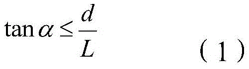
其中L是在第一虚拟源108’1和相位剖面610之间的距离。距离L可以由在图像源和体全息图(即全息组合器660)之间的光学距离来近似。上述标准(1)应该适用于1D光束复制器的第一方向113,或者适用于2D光束复制器的两个方向中的每一个。当使用1D复制器时,可以使用具有不对称出射光瞳的图像源或投影仪。例如,出射光瞳可以在图像光束复制的方向上保持小,而在图像光束不被复制的正交方向上,出射光瞳可以扩大以在视窗上的相应维度上提供足够宽的覆盖。where L is the distance between the first virtual source 108'1 and the
回来参考图1、图3和图5,组合器160的替代实施例可以包括例如图案化的超颖表面,其包括交替的金属和电介质和/或金属/半导体层的叠层。投影仪108可以包括具有电子显示器和光束准直光学器件的图像投影仪,用于将由电子显示器显示的图像转换成在角域中的投影图像。也可以使用全息投影仪,例如由激光光源和相位和/或振幅空间光调制器(SLM) 形成的那些全息投影仪。全息投影仪有具有可变焦距和/或能够至少部分地补偿组合器160的光学像差的优点。创建具有小于重复在全息组合器160 中的相位剖面的步长大小K的出射光瞳的显示器可能是优选的。Referring back to FIGS. 1 , 3 and 5 , alternative embodiments of the
用于通过NED显示图像的方法可以包括接收图像光的第一光束,例如图1、图3和图5中的第一光束101。第一光束可以被分离成图像光的多个第二光束,例如图1、图3和图5中的第二光束102。光束分离可以例如由分别是图2A、图2B、图2C、图2D、图2E和图2F的波导图像复制器200A、200B、200C、200D、200E或200F执行。光束分离也可以例如由图3、图4A和图4B的基于反射镜叠层的图像复制器340、图4C的 440或图5的540执行。然后,多个第二光束可以被中继到NED的视窗,使得在视窗处的第二光束在第一方向上横向地偏移。可以例如通过使用图 1的组合器160、图6的全息组合器660和/或包括超颖表面的组合器来完成中继。如上面所解释的,第一光束可以是发散的,并且包括在角域中的图像;由图像复制器分离的第二光束可以是发散的,并且由组合器中继的第二光束在视窗处可以是会聚的,平行于彼此,并且包括在角域中的图像。A method for displaying an image by an NED may include receiving a first beam of image light, such as the
参考图9A和图9B,近眼AR/VR显示器900包括近眼相干AR/VR显示器900的主体或框架902,具有一副眼镜的形状因子,如所示。显示器 904包括显示组件906,将图像光908提供到视窗910,即几何区域,其中高质量图像可以被呈现给用户的眼睛912。显示组件906可以包括分别是图1、图3和图5的NED 100、NED 300和NED 500中的任一个。可以为每只眼睛提供单独的AR/VR显示模块,或者为两只眼睛提供一个AR/VR显示模块。对于后一种情况,光学切换设备可以耦合到单个电子显示器,用于以时间顺序方式将图像引导到用户的左眼和右眼,一帧针对左眼以及一帧针对右眼。图像以足够快地(即以足够快的帧速率)被呈现,使得各个眼睛没有注意到闪烁,并且感知周围虚拟或增强场景的流畅、稳定的图像。Referring to FIGS. 9A and 9B , a near-eye AR/
显示组件906的电子显示器可以例如且没有限制地包括液晶显示器 (LCD)、有机发光显示器(OLED)、无机发光显示器(ILED)、有源矩阵有机发光二极管(AMOLED)显示器、透明有机发光二极管(TOLED) 显示器、投影仪、扫描激光束显示器、硅上液晶(LCOS)显示器、相位空间光调制器(SLM)或其组合。近眼相干AR/VR显示器900还可以包括用于实时地确定用户的眼睛912的凝视方向和/或聚散角(vergence angle)的眼睛跟踪系统914。所确定的凝视方向和聚散角可以用于切换在图像复制器的反射镜叠层中的可变反射镜,并且还可以用于取决于视角和眼睛位置的视觉伪像的实时补偿。此外,所确定的聚散度和凝视角度可用于与用户的交互作用、加亮对象、将对象带到前景、动态地创建附加对象或指针等。近眼相干AR/VR显示器900还可以包括音频系统,例如小扬声器或头戴式耳机。The electronic display of
现在转到图10,HMD 1000是围住用户的面部的AR/VR近眼可穿戴显示系统的示例,用于到AR/VR环境内的更大程度的沉浸。HMD 1000 可以作为AR/VR系统的一部分向用户呈现内容,该AR/VR系统还可以包括用户位置和定向跟踪系统、外部摄像机、手势识别系统、用于向系统提供用户输入和控制的控制装置以及用于存储软件程序和其他数据的中央控制台,软件程序和其他数据用于与用户交互作用,用于与AR/VR环境交互作用。HMD 1000的功能是用计算机生成的影像来增强物理、真实世界环境的视图,和/或生成完全虚拟的3D影像。HMD 1000可以包括前主体1002和带1004。前主体1002被配置为以可靠且舒适的方式放置在用户的眼睛前面,并且带1004可以被拉伸和/或调整以将前主体1002固定在用户的头部上。显示系统1080可以包括分别为图1、图3和图5的NED 100、 NED 300和NED 500。显示系统1080可以布置在前主体1002中,用于向用户呈现AR/VR影像。前主体1002的侧面1006可以是不透明的或透明的。Turning now to FIG. 10 ,
在一些实施例中,前主体1002包括定位器1008、用于跟踪HMD 1000 的加速度的惯性测量单元(IMU)1010以及用于跟踪HMD 1000的位置的位置传感器1012。定位器1008由虚拟现实系统的外部成像设备跟踪,使得虚拟现实系统可以跟踪整个HMD 1000的位置和定向。为了HMD 1000 的位置和定向的改进的跟踪,由IMU和位置传感器1012生成的信息可以与通过跟踪定位器1008获得的位置和定向比较。当用户在3D空间中移动和转动时,准确的位置和定向对于向用户呈现适当的虚拟场景是重要的。In some embodiments, the
HMD 1000还可以包括实时地确定用户的眼睛的定向和位置的眼睛跟踪系统1014。眼睛的所获得的位置和定向允许HMD 1000确定用户的凝视方向,并相应地调整由显示系统1080生成的图像。在一个实施例中,确定聚散度,即用户的眼睛凝视的会聚角度。所确定的凝视方向和聚散角可以用于切换在图像复制器的反射镜叠层中的可变反射镜,并且还可以用于取决于视角和眼睛位置的视觉伪像的实时补偿。此外,所确定的聚散度和凝视角度可用于与用户的交互作用、加亮对象、将对象带到前景、创建附加对象或指针等。还可以提供音频系统,其包括例如内置到前主体1002 中的一组小扬声器。The
用于实现关于本文公开的方面描述的各种说明性逻辑、逻辑块、模块和电路的硬件可以用被设计成执行本文所述的功能的通用处理器、数字信号处理器(DSP)、专用集成电路(ASIC)、现场可编程门阵列(FPGA) 或其他可编程逻辑器件、分立门(discrete gate)或晶体管逻辑、分立硬件部件或其组合来实现或执行。通用处理器可以是微处理器,但是可选地,处理器可以是任何传统的处理器、控制器、微控制器或状态机。处理器还可以被实现为计算设备的组合,例如DSP和微处理器的组合、多个微处理器、与DSP核心结合的一个或更多个微处理器或任何其他这样的配置。可选地,一些步骤或方法可以由特定于给定功能的电路执行。Hardware for implementing the various illustrative logics, logic blocks, modules, and circuits described with respect to aspects disclosed herein can be implemented using general-purpose processors, digital signal processors (DSPs), application-specific integrated Circuit (ASIC), field programmable gate array (FPGA) or other programmable logic device, discrete gate (discrete gate) or transistor logic, discrete hardware components or a combination thereof to realize or execute. A general-purpose processor can be a microprocessor, but in the alternative, the processor can be any conventional processor, controller, microcontroller, or state machine. A processor may also be implemented as a combination of computing devices, eg, a combination of a DSP and a microprocessor, multiple microprocessors, one or more microprocessors in combination with a DSP core, or any other such configuration. Alternatively, some steps or methods may be performed by circuitry specific to a given function.
本公开在范围上不被本文描述的特定实施例限制。实际上,除了在本文描述的那些实施例和修改之外,其他各种实施例和修改也将从前述描述和附图中对本领域中的普通技术人员明显。因此,这样的其他实施例和修改意欲落在本公开的范围内。此外,尽管本文为了特定目的在特定环境中在特定实现的上下文中描述了本公开,但是本领域中的普通技术人员将认识到它的有用性不限于此,并且本公开可以为了任何数量的目的在任何数量的环境中而被有益地实现。因此,应该鉴于如本文描述的本公开的全广度和精神来解释所阐述的权利要求。The present disclosure is not to be limited in scope by the particular embodiments described herein. Indeed, various other embodiments and modifications in addition to those described herein will become apparent to those skilled in the art from the foregoing description and accompanying drawings. Accordingly, such other embodiments and modifications are intended to fall within the scope of this disclosure. Furthermore, although the disclosure is described herein in the context of a particular implementation in a particular environment for a particular purpose, those of ordinary skill in the art will recognize that its usefulness is not limited thereto and that the disclosure may serve any number of purposes Beneficially implemented in any number of environments. Accordingly, the set forth claims should be construed in view of the full breadth and spirit of the disclosure as described herein.
Claims (19)
Applications Claiming Priority (3)
| Application Number | Priority Date | Filing Date | Title |
|---|---|---|---|
| US16/111,171 | 2018-08-23 | ||
| US16/111,171 US11022799B2 (en) | 2018-08-23 | 2018-08-23 | Projector-combiner display with beam replication |
| PCT/US2018/048202 WO2020040794A1 (en) | 2018-08-23 | 2018-08-27 | Projector-combiner display with beam replication |
Publications (2)
| Publication Number | Publication Date |
|---|---|
| CN112602004A CN112602004A (en) | 2021-04-02 |
| CN112602004B true CN112602004B (en) | 2023-04-04 |
Family
ID=63668012
Family Applications (1)
| Application Number | Title | Priority Date | Filing Date |
|---|---|---|---|
| CN201880096871.4A Expired - Fee Related CN112602004B (en) | 2018-08-23 | 2018-08-27 | Projector-combiner display with beam replication |
Country Status (4)
| Country | Link |
|---|---|
| US (1) | US11022799B2 (en) |
| EP (1) | EP3841424A1 (en) |
| CN (1) | CN112602004B (en) |
| WO (1) | WO2020040794A1 (en) |
Families Citing this family (19)
| Publication number | Priority date | Publication date | Assignee | Title |
|---|---|---|---|---|
| US11150468B1 (en) * | 2019-08-07 | 2021-10-19 | Facebook Technologies, Llc | Optical device having reduced diffraction artifacts for eye-tracking |
| KR102781216B1 (en) * | 2019-08-19 | 2025-03-18 | 삼성디스플레이 주식회사 | Electronic device and wearable electronic device |
| US11175509B2 (en) * | 2019-09-30 | 2021-11-16 | Microsoft Technology Licensing, Llc | Tuned waveguides |
| WO2021092314A1 (en) | 2019-11-06 | 2021-05-14 | Hes Ip Holdings, Llc | System and method for displaying an object with depths |
| US11892633B2 (en) * | 2019-12-23 | 2024-02-06 | Samsung Electronics Co., Ltd. | Display apparatus including volume grating based combiner |
| WO2021157044A1 (en) * | 2020-02-07 | 2021-08-12 | 株式会社島津製作所 | Display device and optical element for use in said display device |
| TWI897971B (en) * | 2020-06-01 | 2025-09-21 | 以色列商魯姆斯有限公司 | Virtual image delivery system for near eye displays |
| US12298512B2 (en) | 2020-06-19 | 2025-05-13 | Oomii Inc. | Image display systems for eyebox expansion and methods of making the same |
| WO2022086002A1 (en) | 2020-10-20 | 2022-04-28 | Samsung Electronics Co., Ltd. | Waveguide structure with segmented diffractive optical elements and near-eye display apparatus employing the same |
| KR20220077724A (en) | 2020-12-02 | 2022-06-09 | 삼성전자주식회사 | Display apparatus employing meta surface |
| CN117099014A (en) * | 2021-03-01 | 2023-11-21 | 图达通智能美国有限公司 | Fiber-based transmitter and receiver channels for light detection and ranging systems |
| CN112904585B (en) * | 2021-04-21 | 2022-11-08 | 南昌三极光电有限公司 | Optical system |
| US20230003857A1 (en) * | 2021-06-28 | 2023-01-05 | Seagate Technology Llc | Lidar with polarized waveguide |
| GB2610871B (en) * | 2021-09-21 | 2025-03-12 | Envisics Ltd | Pupil expander integrity |
| US20230176367A1 (en) * | 2021-12-06 | 2023-06-08 | Meta Platforms Technologies, Llc | Lightguides with color- and time-sequential gratings |
| US12429651B2 (en) | 2022-05-12 | 2025-09-30 | Meta Platforms Technologies, Llc | Waveguide with tunable bulk reflectors |
| GB2618630B (en) * | 2022-10-20 | 2024-08-07 | Envisics Ltd | Hologram calculation for compact head-up display |
| GB2631995A (en) * | 2023-07-21 | 2025-01-22 | Envisics Ltd | Interlaced hologram replication |
| GB2636355A (en) * | 2023-12-06 | 2025-06-18 | Allfocal Optics Ltd | Head-up display projector unit |
Family Cites Families (17)
| Publication number | Priority date | Publication date | Assignee | Title |
|---|---|---|---|---|
| IL148804A (en) | 2002-03-21 | 2007-02-11 | Yaacov Amitai | Optical device |
| GB0902468D0 (en) | 2009-02-16 | 2009-04-01 | Light Blue Optics Ltd | Optical systems |
| CA2758633C (en) | 2009-04-14 | 2017-09-26 | Bae Systems Plc | Optical waveguide and display device |
| US9671566B2 (en) | 2012-06-11 | 2017-06-06 | Magic Leap, Inc. | Planar waveguide apparatus with diffraction element(s) and system employing same |
| GB201212270D0 (en) | 2012-07-10 | 2012-08-22 | Light Blue Optics Ltd | Head up displays |
| WO2014207452A1 (en) | 2013-06-26 | 2014-12-31 | Bae Systems Plc | Display comprising an optical waveguide for displaying an image |
| FR3014209B1 (en) | 2013-11-29 | 2017-03-03 | Commissariat Energie Atomique | OUTPUT PUPIL EXTENSION DEVICE AND HIGH HEAD VIEWER HAVING THE DEVICE |
| JP6451210B2 (en) | 2014-10-29 | 2019-01-16 | セイコーエプソン株式会社 | Display device |
| JP6520209B2 (en) * | 2015-02-27 | 2019-05-29 | セイコーエプソン株式会社 | Image display device |
| JP6477051B2 (en) | 2015-03-09 | 2019-03-06 | セイコーエプソン株式会社 | Image display device |
| CN104950366B (en) * | 2015-06-29 | 2017-06-06 | 西安交通大学 | A kind of diffraction zone modulator approach of Bragg reflector types concave diffraction grating |
| KR20170019086A (en) | 2015-08-11 | 2017-02-21 | 삼성전자주식회사 | A back light unit and a display apparatus |
| US9791696B2 (en) | 2015-11-10 | 2017-10-17 | Microsoft Technology Licensing, Llc | Waveguide gratings to improve intensity distributions |
| JP6720316B2 (en) | 2016-01-06 | 2020-07-08 | ビュージックス コーポレーションVuzix Corporation | Two-channel imaging light guide with dichroic reflector |
| US9964768B2 (en) * | 2016-03-04 | 2018-05-08 | Sharp Kabushiki Kaisha | Head mounted display using spatial light modulator to generate a holographic image |
| CN110023819B (en) | 2016-11-30 | 2022-05-17 | 奇跃公司 | Method and system for high resolution digital display |
| US10955668B2 (en) * | 2017-02-14 | 2021-03-23 | Optecks, Llc | Optical display system for augmented reality and virtual reality |
-
2018
- 2018-08-23 US US16/111,171 patent/US11022799B2/en active Active
- 2018-08-27 CN CN201880096871.4A patent/CN112602004B/en not_active Expired - Fee Related
- 2018-08-27 EP EP18773688.9A patent/EP3841424A1/en not_active Withdrawn
- 2018-08-27 WO PCT/US2018/048202 patent/WO2020040794A1/en not_active Ceased
Also Published As
| Publication number | Publication date |
|---|---|
| US11022799B2 (en) | 2021-06-01 |
| EP3841424A1 (en) | 2021-06-30 |
| US20200064633A1 (en) | 2020-02-27 |
| WO2020040794A1 (en) | 2020-02-27 |
| CN112602004A (en) | 2021-04-02 |
Similar Documents
| Publication | Publication Date | Title |
|---|---|---|
| CN112602004B (en) | Projector-combiner display with beam replication | |
| JP7568757B2 (en) | Display device for expanding the field of view | |
| US12092815B2 (en) | Methods and systems for generating virtual content display with a virtual or augmented reality apparatus | |
| CN113508321B (en) | Optical system with optical expansion coupler | |
| CN113795782B (en) | Provides concentric light field and monocular-binocular hybrid display system | |
| EP3535624B1 (en) | Holographic projector for waveguide display | |
| CN109642716B (en) | Virtual, augmented and mixed reality systems including thick media and related methods | |
| JP5060704B2 (en) | Flat projection display | |
| CN113412437A (en) | Optical hyper-focal reflective systems and methods and augmented reality and/or virtual reality displays incorporating the same | |
| TW202235939A (en) | Staircase in-coupling for waveguide display | |
| US20200408979A1 (en) | Backlight device, holographic display including the same, and method of manufacturing holographic optical element having a multilayered structure | |
| US11423814B2 (en) | Wearable display with coherent replication | |
| CN103765294A (en) | Lightweight eyepiece for head mounted display | |
| CN106200339A (en) | Film type controlled viewing window back light unit and use its Boping type controlled viewing window display | |
| TW202235958A (en) | Waveguide display with multiple monochromatic projectors | |
| US20230176382A1 (en) | Waveguide display with cross-polarized eye pupil expanders | |
| US20200081255A1 (en) | Light guide with polarization separator for dual images | |
| US20240168290A1 (en) | Holographic vr display | |
| TW202332960A (en) | Waveguide with polarization volume hologram grating | |
| CN118466043B (en) | Multi-focal-plane holographic optical waveguide display system | |
| TW202319789A (en) | Waveguide with a beam splitter upstream of output region | |
| CN113302526A (en) | Waveguide with partial reflector | |
| TW202409643A (en) | Light guide illumination assembly for providing increased contrast | |
| EP4191293A1 (en) | Waveguide-type display apparatus | |
| JPWO2023057543A5 (en) |
Legal Events
| Date | Code | Title | Description |
|---|---|---|---|
| PB01 | Publication | ||
| PB01 | Publication | ||
| SE01 | Entry into force of request for substantive examination | ||
| SE01 | Entry into force of request for substantive examination | ||
| CB02 | Change of applicant information |
Address after: California, USA Applicant after: Yuan Platform Technology Co.,Ltd. Address before: California, USA Applicant before: Facebook Technologies, LLC |
|
| CB02 | Change of applicant information | ||
| GR01 | Patent grant | ||
| GR01 | Patent grant | ||
| CF01 | Termination of patent right due to non-payment of annual fee |
Granted publication date: 20230404 |
|
| CF01 | Termination of patent right due to non-payment of annual fee |