This application claims the benefit of priority from U.S. patent application 15/860,212 filed on day 1, month 2, 2018, U.S. patent application 15/860,212 claims the benefit of priority from U.S. patent application 14/499,288 filed on day 9, month 29, 2014, U.S. patent application 14/499,288 claims the benefit of priority from U.S. provisional patent application 62/021,033 filed on day 7, month 4, 2014, and the entire disclosures of these applications are incorporated herein by reference.
Disclosure of Invention
Described herein are articles and containers and methods for handling FOG. In accordance with at least one embodiment, an article for handling FOG is disclosed. In some examples, the article may include a top portion including a top opening and a perimeter rim, and a body portion connected to and located below the top portion. In some examples, the body portion may include a continuous FOG-impermeable film, an upper body portion having a first maximum width, and a lower body portion having a second maximum width and a concave shape. Further, the body portion may include a body intermediate surface separating the upper and lower body portions and may be configured to rest on at least a portion of a first bottom surface of the sink surrounding the first drain pipe. The lower body portion may also be sized to fit within the first drain pipe.
In some examples of the article, the interior of the body may further comprise a FOG absorbent material. In some examples, the upper body portion may have a top maximum width adjacent the top portion and a bottom maximum width adjacent the body intermediate surface. In some examples, the top maximum width may be greater than the bottom maximum width.
In some examples of the article, the lower body portion can have an upper maximum width adjacent the body intermediate surface and a lower maximum width defining a bottom of the body portion. The upper maximum width may be greater than the lower maximum width. In some examples of articles, the body intermediate surface may be flat.
In some examples of the article, the first drain tube may have a first maximum drain width that is greater than a second maximum width of the lower body portion. In some examples, the first drain pipe may have a depth that is less than a height of the lower body portion. In some examples, the body intermediate surface may have a maximum intermediate surface width that is greater than the first maximum drainage width.
In some examples, the top opening may be defined by a perimeter edge. In some examples, the perimeter rim may be configured to be placed on at least a portion of a second bottom surface of the second sink that surrounds a second drain pipe having a second maximum drain width. In some examples, the upper body portion may be concave and sized to fit within the second drain pipe. In some examples, the perimeter edge may have a maximum width that is greater than the second maximum drainage width. In some examples, the second maximum drainage width may be greater than the first maximum drainage width.
In some examples, the first maximum width of the upper body portion can be less than a second maximum drain width of a second drain conduit sized to receive the upper body portion of the article. In some examples, the first maximum width may be greater than the second maximum width. In some examples, the exterior of the body portion may be defined by a continuous FOG-impermeable film.
In accordance with at least another embodiment, a container for handling FOG is disclosed. In some examples, the container may include an integrally formed continuous outer shell including an at least partially hollow interior, a top portion having a top opening, a liquid impermeable bottom portion, and a liquid impermeable upper portion connected to and contiguous with both the top portion and the bottom portion. In some examples, the container may further include a middle portion separating the top portion and the bottom portion and including at least one middle edge for placing the container on the first surface surrounding the first drain pipe. The first drain tube may have a first maximum width and the bottom portion may have a shape that at least partially conforms to the hollow interior of the drain tube to be at least partially disposed within the interior of the first drain tube. The housing may be configured to receive the FOG through the top opening without the FOG exiting through the bottom portion or the upper portion. In some examples, the bottom portion may include a second maximum width that is less than the first maximum width of the first drain pipe.
In some examples of the container, the at least one intermediate edge may comprise a flat surface for placing the container on the first surface surrounding the first drain pipe. In some examples, the planar surface may have a third maximum width that is greater than the first maximum width. In some examples, the top portion may include at least one top edge for placement on a second surface surrounding a second drain pipe having a fourth maximum width. In some examples, the at least one top edge may include an edge having a fifth maximum width that is greater than the fourth maximum width. In some examples, the fourth maximum width may be greater than the first maximum width, and the upper portion may have a sixth maximum width that is less than the fourth maximum width and greater than the second maximum width. In some examples, the at least one intermediate edge may include at least two edges.
According to another embodiment, a method for handling FOG is disclosed. The method may include positioning at least one edge of the container on a first bottom surface of the sink surrounding a first drain of the sink such that a top opening of a top portion of the container faces upward and at least some body portion of the container is located below the first bottom surface and within the first drain. In some examples, the body portion has a FOG-impermeable film. In some examples, the method may further include pouring the FOG into the body portion of the container through the top opening, the container preventing the FOG from passing down through the first drain.
In some examples of the method, positioning may include resting at least two edges of the container on the first bottom surface. In some examples, the at least two edges may be located on different sides of the container. In some examples, the at least two edges may be located on opposite sides of the container.
In some examples, the at least one edge may include a first perimeter edge. And in some examples, positioning may include resting the first perimeter edge of the container on the first bottom surface. In some examples, the first perimeter boundary may be located at a top portion of the container. In some examples, the first perimeter boundary edge may be located at the body portion. In some examples, the body portion may include an upper body portion and a lower body portion. In some examples, the first perimeter edge may separate the upper-body portion and the lower-body portion.
In some examples, the body portion may have a first maximum width, and the first drain pipe may have a second maximum width greater than the first maximum width. And in some examples, the first perimeter boundary edge may have a third maximum width that is greater than the second maximum width. In some examples, the container may include a second perimeter edge having a fourth (or second perimeter) maximum width that is greater than the third maximum width. In some examples, the method may further include resting the second perimeter edge on a second bottom surface of the sink surrounding the second drain. In some examples, the second drain pipe may have a fifth maximum width that is less than the fourth maximum width. In some examples, the fifth maximum width may be greater than the second maximum width.
In some examples, the body portion may have a concave shape, and the positioning may include positioning at least one edge of the container on the first bottom surface such that at least some of the concave body portion is located within the first drain tube. In some examples, the interior of the body portion may include an absorbent material. In some examples, the method may further include absorbing at least some of the FOG poured into the body portion with an absorbent material.
In some examples, the FOG-impermeable membrane of the body portion may be liquid-impermeable. In some examples, the body portion may be connected to and located below the top portion. In some examples, the FOG-impermeable film may be continuous.
In accordance with at least another embodiment, an article for handling FOG is disclosed. The article may include a peripheral rim defining a top opening configured to be placed on a kitchen sink bottom surface surrounding an internal hollow-type drain pipe, such that the article body into which the FOG is poured may be located below both the peripheral rim and the top opening, and may generally (but not always) be located at or below a lower height than the sink bottom surface, and fit within the internal hollow portion of the drain pipe, the body having a shape capable of stably resting within the drain pipe cavity and maximizing the volume that receives the FOG poured therein. In the event that the article body has a shape that conforms to the interior hollow cavity of the drain pipe and is configured to stably fit within the interior hollow cavity of the drain pipe, the FOG can be poured into the top opening of the article, where it can be stored, rather than entering the drain pipe. Since many kitchen sink drains have a circular cross-section (the interior of the ring forms the drain surface defining the drain cavity), in many embodiments, the peripheral edge of the article may be circular with a circumference wider than the top of the drain adjacent the bottom surface of the kitchen sink.
In some embodiments, the article body can include a membrane perimeter made of a liquid-impermeable stiff inner liner material or other rigid outer membrane that is liquid-impermeable FOG. Other embodiments may include an outer membrane (i.e., a membrane perimeter) that is substantially liquid-impermeable FOG. For example, in one embodiment, the outer film may be comprised of corrugated cardboard or recycled paper that is molded into a predetermined drainage shape (e.g., molded using a molded pulp process).
In some examples, article embodiments may also include an interior section of absorbent material for converting FOG absorbed thereby from a liquid or semi-liquid state to a solid or semi-sold state. In one embodiment, the absorbent material may be at least partially surrounded by an outer membrane to prevent FOG from passing through the (potentially supersaturated) absorbent material and into the drain. In some embodiments, the entire lower interior of the membrane body may be filled with an absorbent material. The absorbent material may be configured to receive the FOG through the top opening. The absorbent material may also include materials and designs (as described in more detail below) or other absorbent members for maximizing the amount of FOG that can be absorbed with limited bulk volume (or, for embodiments that include a container, the size of the container). In one embodiment, the FOG absorbent material may comprise polyurethane, and in a particular embodiment, may also resemble a foam sponge composed of a cellulosic material, such as wood pulp or other earth-friendly substance. In some embodiments, the entire article and/or portions thereof may be disposable and/or biodegradable. For embodiments including an absorbent member, the container may be placed in a trash can with less risk of container puncture (which would result in the FOG contents leaking into the remainder of the waste in the container) when the FOG transitions from a liquid state to at least a semi-solid state.
The article may also include additional features for maximizing FOG absorption, for example in one embodiment, a cover for placement in the top opening for distributing FOG poured thereon over the absorbent material in a predetermined manner to increase FOG saturation of the absorbent material. In one embodiment, the cover may have a radially positioned array of slit annular openings for distributing liquid onto the absorbent material, the slits having a narrower width to keep trapped and coagulated FOG contained within the body for disposal. In addition to or as an alternative to the absorbent material or other absorbent member, some embodiments of the body may include an interior adsorbent surface (which in another embodiment may include a removable liner made of, for example, aluminum foil or heavy-duty paper such as waxed paper).
In one embodiment, the article may include a predetermined size and/or body volume (and amount of absorbent material) for containing an amount of FOG cooking by-products generated for a single household cooking example. For example, in one particular embodiment, the body may have a volume for accommodating substantially four ounces of FOG; and an absorbent member configured to receive a maximum amount of FOG within the body volume. The size intended to achieve the best efficient single use without the need for additional usage to effectively utilize the container without wasting container material may allow the user to eliminate cumbersome and time consuming handling steps such as multiple storage, sealing and unsealing of the lid, and placing the container in a refrigerator or freezer.
In one embodiment, the outer membrane of the body configured to be placed in the interior hollow portion of the drain pipe is rigid (to prevent, among other benefits, hot liquid FOG poured thereon from damaging the appearance of the membrane) and forms a container that rests stably in the drain pipe, the sides of the container not extending significantly above the level of the bottom surface of the kitchen sink when the FOG is poured into the container through the top opening, thus making it possible to keep the cooking appliance pouring FOG at a lower elevation and in a more advantageous position. In some container embodiments, the outer film comprises a rigid shell for receiving, holding, and disposing the FOG, which rigid shell is separable from the portion of the article comprising the absorbent member. Thus, in some embodiments, the FOG absorbent or absorbent member can be discarded without having to discard the remainder of the article. In other container embodiments, the entire article may be designed to be conveniently disposed of with the FOG absorbent/absorbent member.
The shape of the body configured to rest in the drain pipe may also provide greater stability and less difficulty in handling when pouring in FOG. Also, in one embodiment, the body may include an inner surface that may be continuously downwardly sloped, such that the FOG continues to flow downwardly due to gravity and first fills the lowermost portion of the container interior, or otherwise strategically transfers liquid FOG to the absorbent material section. In case the article is stably placed in the drain, the FOG can be poured into it with less risk of spillage until the FOG absorbing member is fully saturated to the maximum and/or until the adsorbing member also reaches its full capacity. In one embodiment, the article body can include a rigid flat bottom surface for placing the container on another flat surface, such as a countertop, without fear that the FOG will spill. In certain embodiments having downwardly sloping sides (and as described in more detail in the description of the figures), the flat bottom surface may have a width of substantially 2.6 inches. Some embodiments (not necessarily limited to embodiments of a removable shell or container) may also include other features for more convenient and/or safer handling of the article, such as a perimeter rim that includes legs or buttresses or other members for keeping the remainder of the perimeter rim sufficiently elevated above (but still not substantially above) the bottom surface of the kitchen drain surface to facilitate finger gripping of the article and removal from the drain after the FOG is poured therein.
Thus, embodiments of the articles, containers, and methods make it possible to dispose of FOG in a more rapid, economical, efficient, environmentally friendly, regulatory compliant, and safe manner. The above-described embodiments are to be considered merely as examples of articles, containers, and methods. It is to be understood that the embodiments shown in the following drawings and described above are for illustrative purposes only and are not intended to limit the scope. Accordingly, variations, modifications, and further applications that would occur to one skilled in the relevant art are also contemplated.
Detailed Description
For many people, prior art articles, methods and apparatus for handling FOG do not provide a sufficiently attractive alternative to pouring FOG into drain pipes at all. Pouring hot liquid FOG directly into a trash can, for example, is certainly not a desirable practice as it can burn out waste, trash bags, and damage trash containers and even fire. Condensed FOG stored in a trash can also begin to emit noxious odors. Placing the FOG into a bag or container with a non-rigid or thin membrane and then into a trash can is also not desirable because the container/bag may be punctured and the FOG may be reheated at some point, causing the FOG to return to its liquid and potentially problematic form. In addition to the risk of piercing, non-rigid and thin container films (such as those made of certain plastics and/or thin metal foils) may also be melted by or deformed by hot liquid FOG, and/or bent by the weight of FOG or foreign objects poured thereon. For example, after pouring a liquid FOG into a container/bag having a non-rigid membrane, such container/bag more readily assumes the shape of the interior liquid contents and is therefore difficult to handle, thereby increasing the likelihood of spillage. The risk of spillage is even greater when/if the bag is not sealed very quickly after the FOG is placed in the bag. Similarly, if such a bag opening is not completely sealed, the absence of a substantially rigid membrane may increase the likelihood of FOG leaking and spilling through the cracks in the seal.
On the other hand, containers/bags having thicker and more water-impermeable films are generally more costly to produce. Since these costs are often passed on to the consumer, and prior art containers/bags containing coagulated FOG must often be disposed of with the FOG, it may be impractical for cost conscious consumers to frequently use and dispose of such more expensive containers/bags. In addition to higher cost, many such containers/bags with thicker water impermeable films (even those with thinner, more water permeable films) are less biodegradable and therefore more environmentally hazardous. For example, although some containers may be recyclable when uncontaminated by FOG, clotted and adhered FOG may eliminate this function, possibly resulting in additional environmental hazards (especially if the container is not biodegradable).
Many prior art containers/bags of much larger dimensions than the volume in which the liquid FOG is placed may also unnecessarily (but slightly) increase environmental hazards. In particular, when discarding said oversized container, which is only partially filled with FOG, in a trash can, unnecessary container material is wasted and also more space in the trash can is taken up. On the other hand, when using such larger containers/bags to dispose of the FOG in a manner that does not waste material-requiring repeated use for different instances of the cooking activity that produces the FOG multiple times to "fill" the volume of the container-more time consuming steps are required to properly dispose of. For example, many containers/bags appear to be designed to hold about one quart of FOG or more, but the FOG by-product from a non-commercial cooking session is typically much less than one quart. It is not uncommon, for example, for a household cook to produce an amount of FOG by-product that is no greater than 4 ounces, and is in the range of 2 ounces to 6.5 ounces. Regardless of the precise amount of FOG by-product produced, larger containers/bags often must be reused multiple times prior to disposal to avoid waste of container material, and thus require additional and time consuming steps associated with such reuse. These steps include, for example, proper storage of the FOG and container during the interim period between each addition of FOG byproduct from different cooking examples, during which time bacteria and pests may be attracted and/or unpleasant odors may be emitted. In an attempt to address these and other negative effects, containers/bags containing FOG are often placed in a refrigerator or freezer, thus requiring additional space, attention, and time, or are sealed, for example, with a removable lid, and then unsealed when more FOG is to be placed therein, with additional time required for sealing and unsealing. It can be said that due to a number of different factors, the additional step of disposing of the FOG multiple times using the container/bag without wasting (which can be expensive) container material can be undesirable (e.g., too time consuming) and can result in improper disposal of the FOG by a person, such as pouring it into a drain. While it is desirable to have a disposable, environmentally friendly article that eliminates some of the disposal steps and provides a practical, cost effective, non-wasteful solution to effectively and properly dispose of the FOG, few disposable articles are specifically designed to only dispose of the limited amount of FOG produced in a single cooking at home (such disposability is highly efficient and does not require re-use) to avoid wasting material.
It would be further desirable if such novel articles existed and also included other features to facilitate easy and safe use (e.g., pouring) without having to waste material and/or significantly increase cost. For example, a larger container/bag not only is more expensive to produce than a smaller container/bag (other factors being equal), but may also be less usable in the kitchen in some cases, especially when one hand is occupied by holding a cooking appliance containing a FOG. Moreover, although sealing with a lid may help to avoid spillage when placing the container into a trash can, containers with lids are more expensive to manufacture and the cost generally increases with the size of the lid. On the other hand, smaller lids require smaller openings, which provide smaller targets for pouring the FOG into the container.
In addition to the difficulty of use and opening size, a number of other factors can make the pouring of FOG into prior art containers and bags a challenging task. For example, hot "liquid" FOG may include lumps, ash, or even small food particles, and when poured, the inconsistencies may cause flow irregularities. Furthermore, FOG can be produced in various cooking appliances that are not conducive to pouring in a precise manner, such as cooking pans having a gradually curved rim and a flat edge (i.e., without nozzles or other features for collecting or directing a stream of liquid). Moreover, the potentially high temperatures of such cooking appliances, especially when the FOG is still in a hot liquid form shortly after cooking, coupled with potentially dirty, oily and/or oily surfaces, for example, due to heated FOG particles that may have left the cooking appliance during cooking, may result in a cooking appliance that is not well gripped. Similarly, the handle of such appliances may not be designed to provide optimal leverage, a favorable pour point, or control over pouring. For example, in the case of a pan being a cooking utensil, the FOG can typically be poured by holding the pan away from the body with the walls extending therefrom, then slowly tilting one side of the pan toward the container and attempting to visually monitor the flow of the liquid.
The often elevated position of the container/bag often exacerbates the challenge of controlling the pouring of the FOG (whether consciously recognized by the person pouring or not) because placing the container/bag on a tall countertop and the large sides of such prior art containers/bags can cause the top opening of the container/bag to rise, possibly even above the height of the countertop. Such a raised position of the "entry point" of the pouring FOG may require holding the cooking utensil (e.g., pan) that pours the FOG with arms and hands in an even higher and more difficult to control position. However, keeping the hot liquid FOG higher can be more dangerous if the FOG escapes or "jumps" out of the cooking appliance due to high temperatures leaving the boundaries of the cooking appliance. Moreover, to obtain greater stability when holding the cooking appliance in a high pour position, the cooking appliance or its handle may often be grasped with two hands, which may leave two hands free to adjust the position of the container/bag or stabilize the container/bag depending on the point at which the FOG stream is poured, with an unsupported container/bag that may then be inadvertently knocked over by the cooking appliance (which may cause spillage). It is therefore desirable to have a container with a substantially rigid membrane that enables a FOG to be poured more stably in a lower, more controllable and safer location.
Even when liquid FOG is successfully poured into a container/bag and then placed into a trash can as described above, at some point during the disposal process (e.g., from the trash to a waste landfill site), the film of the container/bag may be damaged and the FOG may be reheated and returned to a detrimental liquid form. To possibly prevent this situation, some municipalities prohibit the placement of FOG into trash cans in free-flowing liquid form or in a form that becomes liquid upon heating. However, some municipalities may allow for handling of FOG if bound in a stable solid form. This can be achieved, for example, by absorbing the FOG with a solid or semi-solid medium. While different types of absorbent materials may provide various advantages such as weight, absorption rate, and saturation, few methods and apparatus include designs or shapes for more efficient use of the absorbent material and/or maximizing the space inside the container containing the absorbent material. However, effectively utilizing absorbent materials and maximizing such containers may be beneficial for articles that are intended to integrate space for efficiency, size, and convenience purposes. Therefore, in order to comply with municipal regulations or simply to avoid potential disadvantages associated with FOG in liquid form, it would be beneficial if the container for handling FOG included an absorbent material for converting FOG from a liquid form to a semi-stable solid form (despite the application of heat) in addition to being practical, convenient, effective, disposable, and environmentally friendly. It would be further desirable if such a container included an absorbent material design for maximizing the amount of FOG saturation in a limited amount of absorbent material volume, and included a substantially rigid membrane and design that had stability when FOG was poured therein.
Described herein are such articles for handling FOG that overcome one or more of the above-described challenges, such as those related to: substantially non-rigid films (which can lead to difficult handling, spillage, and bending/deformation of the film at the FOG contact point), elevated entry points (i.e., openings) where the FOG must be poured into the container/bag from an elevated location, wasted container material, time-consuming steps required, excessive price (when the container is disposed after each cook-in session in which the FOG is produced), inability to maximize FOG saturation of the absorbent material, and environmental unfriendliness. The article used to overcome one or more of such challenges may provide consumers with an attractive alternative and practical solution to pouring FOG into a drain (which may pose an environmental hazard), among other benefits.
Instead of pouring FOG into the drain, the relative convenience of securely placing the article in the hollow portion of the drain of the kitchen sink may encourage proper disposal and serve to effectively remind the user not to pour FOG into the drain. Further, a stable position for holding the container within the interior hollow drain without the use of other support devices (such as a funnel) or stabilization by a human hand while pouring FOG into the interior hollow drain may enable a person to use both hands to carefully pour FOG into a product.
Furthermore, placing the product in a substantially lower high position of the drain, such as a position formed along the floor of a kitchen sink, may make it easier and in a more controlled manner to hold a pan or other cooking utensil above the container at a lower point, thereby avoiding the expenditure of more energy and enabling more control. In the event that hot liquid FOG "pops" out of the container or pan, it may also be advantageous to pour at a height below the countertop and/or substantially at the surface of the kitchen sink. Furthermore, keeping it at a low height enables the use of gravity and causes such unstable FOG particles to bounce, and if bouncing does occur, is less likely to cause damage or injury, for example, by burning human skin or causing damage to surrounding objects. For example, by placing the article (and the open top, i.e., the point of entry of the poured FOG) at a lower level in a kitchen drain or garbage disposal, the sides of the kitchen sink can also more effectively act as protective walls that can prevent the FOG from causing injury, damage, or mess to the exterior of the sink area. Moreover, the advantageous location of standing closer to the container and looking down at the product in the drain may also facilitate careful pouring without spillage. Further, the top opening of the article can be sized substantially equal to the width (or diameter) of the drain opening, thereby providing a sufficiently large "target" for pouring FOG (as compared to the narrower openings of some conventional containers). Moreover, because the top opening of some article embodiments may not be substantially wider than the drain opening diameter or substantially taller than the kitchen sink floor around the drain, the article may be placed in the drain without substantially obstructing the area above or around the drain (especially by potentially unused container volume) which may be more readily available for careful handling of the cooking appliance holding and/or pouring the FOG.
Although it may not be necessary to reseal the container (in container embodiments) once the FOG has been absorbed and at least partially converted to solid form, in certain embodiments (including those without an absorbing member), the top opening may be closed and resealed after the FOG is poured therein, and in other embodiments may be reopened and resealed according to user preference.
In some embodiments, the article outer film may also include support bars to provide additional structural support, which may further help maintain the desired shape without the need for a thicker outer film. It is further contemplated that in one embodiment, the article may comprise a material that not only does not penetrate hot liquid FOG, but may also include a heat absorbing material on the outside, thereby enabling grasping and holding without risk of burning a person's hand.
Turning to the drawings, fig. 1 illustrates a first article embodiment 13 for handling FOG according to various aspects of the present disclosure. The article 13 can include an absorbent material 14 and a top opening 15 over the absorbent material 14, the absorbent material 14 being contained in an outer body perimeter (i.e., an outer film forming the shape of the body) 16, and the top opening 15 being for receiving FOG therethrough, the top opening 15 being defined by a perimeter edge 17, the perimeter edge 17 having a width greater than the width of the body perimeter 16.
Fig. 2 is a top perspective view of the article of fig. 1 according to aspects of the present disclosure. The article 13 may also include a cover 18 for placement over both the top opening 15 and the absorbent material 14 below the top opening 15. In the illustrated embodiment 13, the cover 18, when placed over the top opening 15 defined by the perimeter edge 17, may include a design for more evenly distributing the FOG 19 over the absorbent material 14.
Fig. 3 is a cut-away cross-sectional view of the article of fig. 2 placed in a drain of a kitchen sink according to various aspects of the present disclosure. The peripheral rim 17 may include a size and/or shape adapted to rest on a kitchen sink bottom surface 21 surrounding a drain pipe 22 of the internal hollow type, such that the article body 16 (or a portion thereof) narrower than the rim 17 or below the rim 17 may fit within the drain pipe cavity 20 and rest stably therein. Moreover, the body 16 may include a shape that conforms to the interior hollow drainage lumen 20 and is configured to maximize the amount of absorbent material 14 and the available volume for receiving the FOG 19 therein.
The drain pipe 20 is shown to include a circular cross-section similar to that typically formed along the bottom surface 21 of a kitchen sink. Thus, the peripheral rim 17 of the illustrated article embodiment 13 may also be circular with a circumference greater than the circumference of the top 23 of the drain pipe (adjacent the kitchen sink bottom surface 21) for placement over the drain pipe, and the body 16 may also have a circular cross-section sized to securely place the article 13 within the recessed drain pipe 20. The circumference and/or width of the top opening 15 defined by the peripheral rim 17 may also be substantially similar to the circumference and/or width of the top 23 of the drain pipe, thereby providing a larger "target port" for injecting FOG therefrom. For example, in the illustrated embodiment, the combined width of the top opening 15 and the perimeter edge 17 may be substantially 4.4 inches. In the illustrated embodiment, the height of the perimeter rim 17 may be substantially 0.75 inches or other height such that the top opening 15 is not substantially higher than the height of the sink bottom surface 21, or even substantially comparable to the height of the sink bottom surface 21. In the illustrated embodiment, the height from the top of the perimeter edge 17 to the bottom of the article 13 can be substantially 2.38 inches. In the illustrated embodiment 13, the body 16 may also include an inner surface 24 adjacent the absorbent material 14, the inner surface 24 continuously sloping downward, and in the illustrated embodiment may have a slope of substantially 18 degrees to promote continued downward flow of the FOG 19 such that the absorbent material 14 is more likely to first become saturated from the bottom upward. In this manner, pouring the FOG 19 into the top opening 15 may prevent the FOG 19 from pouring down the drain 20 and into the duct 22 and provide an attractive alternative.
Fig. 4 is a cut-away cross-sectional view of the article of fig. 3 according to various aspects of the present disclosure. In the particular embodiment 13 shown, the absorbent material 14 may have a sponge-like texture (which may include polyurethane) and may convert the liquid FOG 19 absorbed thereby into a more stable state 25 that is solid or semi-sold. So converted, the FOG is ready for proper disposal and can be removed from the drain of fig. 3 and placed on another surface 26 (or in trash) without fear that the solid FOG 25 contents may spill out of the article 13. Moreover, the perimeter body 16 of the illustrated embodiment 13 can be constructed of an environmentally friendly rigid/semi-rigid material (such as a cardboard liner) such that the article 13 can retain its shape even when the liquid FOG 19 therein has not cooled or condensed or transformed into a solid/semi-solid FOG state 25.
Fig. 5 is a top perspective view of a second article embodiment for handling FOG, the article being discrete, in accordance with aspects of the present disclosure. The second article embodiment 27 for properly disposing of the FOG can include a body perimeter that is a shell container 28 that also has a shape for at least partially fitting in the drain pipe 20, similar to the body perimeter previously described for the first embodiment 13 above (in fig. 3), the body perimeter having a circular cross-section, and further including a perimeter rim 32. The second article embodiment 27 can further include a top opening 31 and an absorbent material 29 configured to fit within the shell container 28, and can further include a filter 30 for placement over the top opening 31 and the absorbent material 29. However, the top opening 31 is not necessarily defined by the peripheral rim 32, but may be constituted by an inner lining 35 configured to be placed inside the shell container 28, which lining 35 may also comprise the absorbent material 29. The dimensions of the absorbent material 29 in the second embodiment 27 may also include a predetermined size and/or bulk volume and/or material type for absorbing the amount of FOG cooking by-products produced from one household cooking. The perimeter rim 32 may also include legs 33, the legs 33 serving to hold the remainder of the perimeter rim 32 raised for grasping, as described in more detail below. The second embodiment 27 also includes a trough 34 overflow area, the trough 34 overflow area being used to catch the FOG when the absorbent material 29 is saturated. The channel 34 area may be formed by an outer membrane 36 surrounding the sides of the absorbent material 29, which outer membrane 36 joins/intersects with the downwardly intermediate sloping walls of the inner liner 35.
Fig. 6 is a top perspective view of the article of fig. 5 without separation according to various aspects of the present disclosure. And fig. 7 is a cut-away cross-sectional view of the article of fig. 6 when placed in a kitchen sink drain in accordance with aspects of the present disclosure. As shown in fig. 6, the liner 35 may be placed inside the shell/container 28 (and the liner 35 may also be removed from the shell/container 28), and as shown in fig. 7, the filter 30 may be placed over the top opening 31 and the absorbent material 29, and the article 27 may be placed in the drain pipe 20 along the kitchen sink bottom surface 21 with the legs 33 of the perimeter rim 32 resting along the top of the drain pipe 23 so that the shell/container 28 rests stably inside the drain pipe 20. The trough 34 formed by the outer absorbent liner/membrane 36 and the downwardly intermediate sloping walls of liner 35 can capture any excess FOG 19 that has poured into the filter 30 and top opening 31 but has not been absorbed by the absorbent material 29. After the absorbent material 29 has absorbed the liquid FOG 19 and the excess FOG 19 has been properly disposed of, disposal may be performed by simply disposing of the liner 35 (including the absorbent material 29) after the liner 35 has been separated from the shell/container 28 or the entire article 27. Thus, in one embodiment 27, the shell/container 28 may help to fit more securely within the drain pipe 20 and/or provide an additional discreet layer to ensure that the FOG 19 does not escape from the drain pipe 20.
Fig. 8 is a top perspective view of a third article embodiment for handling FOG according to aspects of the present disclosure. As with the third article embodiment 37 shown in FIG. 8, some embodiments may not necessarily include a housing receptacle 28, but may simply include a rigid outer membrane 38 for placement within the drain 20. Embodiment 37 also need not include a filter 30 (as with the second article embodiment 27 shown in fig. 5-7), but rather can include an exposed top opening 39 defined by a perimeter rim 41, which rim 41 can also be configured to rest on top of the drain pipe 23 adjacent the sink bottom surface 21. The outer film 38 may also be constructed of a substantially rigid material such that when the FOG 19 is placed therein and over the absorbent material 40, the outer film 38 does not lose some of its form.
Fig. 9 is a cut-away cross-sectional view of the article of fig. 8 when placed in a kitchen sink drain in accordance with aspects of the present disclosure. As shown in FIG. 9, the interior hollow portion of the drain tube 20 can have an intermediate section 51 and a bottom section 52, and the outer membrane 38 can also have an intermediate section 53 and a bottom section 54 that generally conform to the intermediate section 51 and the bottom section 52. As shown in fig. 9, in some examples, the cross-section of the middle section 53 may be greater than the cross-section of the bottom section 54, the height of the middle section 53 may be greater than the height of the bottom section 54, and/or the slope of the middle section 53 may be greater than the slope of the bottom section 54. Fig. 10 is a top perspective view of a fourth article embodiment for handling a FOG according to aspects of the present disclosure. Fig. 11 is a cut-away cross-sectional view of the article of fig. 10 according to various aspects of the present disclosure. The configuration of the absorbent material may be varied in a manner intended to maximize the amount of saturation in the case of limited space. As shown in FIG. 10, the fourth article embodiment 42 may include a cone 43 design in the middle and below the top opening 45, the cone 43 design for more evenly distributing the FOGs 19 to the ring of absorbent material 44 surrounding the cone 43. Thus, as shown in fig. 11, when the article 42 is placed over and in the drain pipe 20, and when the FOG 19 is poured through the top opening 45 and onto the cone 43, the FOG 19 may be distributed onto the absorbent material 44 surrounding the cone 43, wherein the top height of the cone 43 may be greater than the height of the absorbent material 44. The cone 43 and other designs may be used to evenly distribute the FOG onto the absorbent material 44.
Fig. 12 is a top perspective view illustrating the article of fig. 1 in its use environment stably positioned in a kitchen sink and receiving a FOG poured therein according to aspects of the present disclosure. Some embodiments, such as those mentioned and described above in their environment of use (e.g., embodiments 13, 27, 37, 42), may be stably positioned in the drain pipe 20 at the bottom of the kitchen sink surface 21 to receive the FOG 19 therein, which may be advantageous in several respects, encouraging proper disposal rather than pouring the FOG 19 down into the drain pipe 20. For example, the perimeter rim 17 (as shown in fig. 12) may rest on top of the drain pipe 23 in a manner that does not substantially rise above the sink bottom surface 21. When the FOG 19 is disposed by pouring the FOG 19 into the top opening 15 of the article 13, this position may enable the cooking appliance 46 from which the FOG is poured to be maintained at a lower and more controlled height by the person 47, and may not be too high above the sink bottom surface 21.
Moreover, the rigidity of the body 16 (fig. 1-3) and its shape configured to fit within the drain pipe 20 and its inability to significantly move laterally may provide increased stability for better control when dumping the FOG 19. In addition, the stability is achieved without holding the article 13 with a hand 48, which also frees both hands 48 of the person 47 to carefully pour the FOG 19 into the article 13. Further, with both the article 13 and the cooking appliance 46 maintained at a lower height, the pouring person 47 may have a more preferred vantage point standing closer to the laterally proximal end of the article 13 and being able to view the article 13 down in the drain 20. Moreover, the occurrence of pouring at a level below the countertop 50 substantially within the boundaries of the sink 49 may also reduce the likelihood that the hot liquid FOG 19 will jump up erratically from the cooking utensil 46 and out of the sink 49 (which may otherwise injure and/or soil surrounding people 47 and objects).
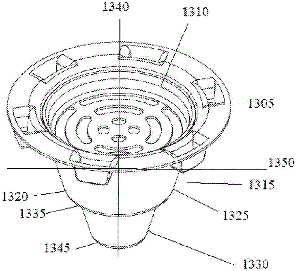
Fig. 13A is a top perspective view of another article embodiment 1300 for handling FOG according to aspects of the present disclosure. The article 1300 may include a top portion 1305 having a top opening 1310. The article 1300 may also include a body portion 1315 connected to the top portion 1305 and located below the top portion 1305. In some examples, the body portion 1315 may include a continuous FOG-impermeable film 1320. In some examples, the FOG-impermeable film 1320 can be located outside of the body portion 1315. In other examples, the FOG-impermeable film 1320 can be located inside the body portion 1315.
In some examples, the body portion 1315 may have an upper body portion 1325 and a lower body portion 1330. The lower body portion 1330 and/or the upper body portion 1325 and/or portions thereof can have a concave shape.
The body portion 1315 may also have a body intermediate surface 1335 that separates the upper body portion 1325 and the lower body portion 1330. In some examples, the body intermediate surface 1335 can have different characteristics than the upper body portion 1325 and/or the lower body portion 1330. For example, in some examples, the body intermediate surface 1335 (and/or a portion of its membrane 1320) may have a different slope or inclination than the upper body portion 1325 and/or the lower body portion 1330 (and/or a portion of its membrane 1320). For example, in one variation, the body intermediate surface 1335, or at least some portion thereof, can be flat, e.g., substantially horizontal or perpendicular to a vertical axis 1340 defined by a line extending from the center of the top opening 1310 to the center of the bottom surface 1345 of the lower body portion 1330.
Although shown in fig. 13A as a circular outwardly projecting edge extending all the way horizontally around body portion 1315, it is to be understood that other variations of body intermediate surface 1335 are also contemplated. For example, in some examples, body intermediate surface 1335 can include at least one edge that can not continuously extend all the way around body portion 1315. In some examples, the at least one edge may include two edges that are, for example, directly opposite only the other edge and are aligned along the same horizontal axis 1350 that is perpendicular to the vertical axis 1340. In some examples, the at least one edge may include three or more edges that are evenly spaced apart but substantially aligned along a horizontal axis 1350 that is perpendicular to the vertical axis 1340. In some examples, at least one edge may have a length (e.g., a distance that the at least one edge extends around a portion of the circumference or exterior of the body portion 1325 along the horizontal axis 1350 at the body intermediate surface 1335) and a width (e.g., a distance from a coordinate of the lower body portion 1330 adjacent to the body intermediate surface 1335 to a coordinate of the upper body portion 1325 along a horizontal axis), as well as other coordinates for defining a dimension and/or a characteristic of the at least one edge.
Fig. 13B is a side perspective view of an embodiment of an article of manufacture of fig. 13A according to aspects of the present disclosure. The upper body portion 1325 can have a first maximum width 1355 and the lower body portion 1330 can have a second maximum width 1360. In some examples, the first maximum width 1355 may be greater than the second maximum width 1360.
Upper body portion 1325 can have a first maximum width 1355 proximate or adjacent to top portion 1305 and a bottom maximum width 1365 proximate body intermediate surface 1335. The top maximum width 1355 may be greater than the bottom maximum width 1365. In some examples, top maximum width 1355 may be less than five inches. In some examples, top maximum width 1355 may be greater than five inches. In some examples, the bottom maximum width 1365 can be greater than two inches. In some examples, the bottom maximum width 1365 may be less than two inches. The lower body portion 1330 can have an upper maximum width 1360 (which can be a second maximum width 1360 in some examples) adjacent to the body intermediate surface 1335, and a lower maximum width 1370, which lower maximum width 1370 can define the bottom surface 1345 of the body portion 1315 in some examples, wherein the upper maximum width 1360 can be greater than the lower maximum width 1370. In some examples, the upper maximum width 1360 may be less than 1.9 inches. In some examples, the upper maximum width 1360 may be greater than 1.9 inches. In some examples, lower maximum width 1370, which may define bottom surface 1345, may be greater than 1.3 inches. In some examples, lower maximum width 1370 defining bottom surface 1345 may be less than 1.3 inches. Body intermediate surface 1335, or a portion thereof, may be flat or have a flat portion 1385 (which may be aligned with horizontal axis 1350 shown in fig. 13A in some examples). Some variations of article 1300 may have substantially different (e.g., larger) dimensions.
The body portion 1315 may have an interior 1375. The interior 1375 may include a FOG absorbing material 1380. The top portion 1305 may also have legs or buttresses 1390.
Fig. 13C is a top view of an embodiment of an article according to aspects of the present disclosure of fig. 13A. The top portion 1305 may include a top opening 1310, and the top opening 1310 may be defined by a perimeter rim 1395. In some examples, and as described above, the top portion can further include a filter portion 1398 for filtering FOG that enters the body portion 1315 from the top opening 1310 (as shown in fig. 13A). Further, the top portion 1305 may include a removable cover 1397, the removable cover 1397 may be transparent or opaque as shown, and may also be provided as a separate component from the top portion 1305 in some examples. In some examples, the removable lid 1397 may be slightly larger/wider than the top portion 1305 to fit over the top portion 1305 and cover the top portion 1305 and seal the article 1300 or container in various ways known to those skilled in the art or ordinary skill.
Fig. 14A is a side view illustrating an article embodiment of fig. 13 in a use environment, in accordance with aspects of the present disclosure. Article 1300-a may be configured to be placed on at least a portion of first bottom surface 1405 of the basin surrounding first drain 1410. In some examples, the body intermediate surface 1335-a may be configured to be placed over at least a portion of the first bottom surface 1405 of the sink surrounding the first drain pipe 1410. In some examples, body intermediate surface 1335-a may include features for stably placing article 1300-a on at least a portion of first bottom surface 1405 of the sink surrounding first drain 1410. In some examples, at least some portions of the body intermediate surface 1335-a may be substantially flat or have substantially the same slope as the first bottom surface 1405. In some examples, body intermediate surface 1335-a may be configured to maximize the area of body intermediate surface 1335-a that may rest on first bottom surface 1405 for greater stability. In some examples, body intermediate surface 1335-a may include legs or braces (not shown), similar to leg pieces 1390.
The lower body portion 1330-a of article 1300-a may be sized to fit within the first drain 1410 when article 1300-a is placed (e.g., when at least one edge of the body middle surface 1335-a is placed or positioned) over at least a portion of the first bottom surface 1405. The first drain tube 1410 may have a first maximum drain width 1415, the first maximum drain width 1415 being greater than a second maximum width 1360-A of the lower body portion 1330-A. In some examples, the body intermediate surface 1335-a may have an intermediate surface maximum width 1430 that is greater than the first maximum drainage width 1415. The first drain tube 1410 may also have a depth 1420 that is greater than a height 1425 of the lower body portion 1330-A. In some examples, the height 1425 of the lower body portion 1330-A may be greater than 1.4 inches. In some examples, the height 1425 of the lower body portion 1330-A can be less than 1.4 inches, such as in the range of about 1 inch to about 4 inches, or any value that can be, for example, less than the depth of a drain in which the lower body portion 1330-A is placed.
Fig. 14B is a side view illustrating the article embodiment 1300-B of fig. 13A in another use environment, in accordance with aspects of the present disclosure. In some examples, the top portion 1305-A may include a top opening 1310-A and may include a perimeter edge 1395-A. Further, in some examples, the top opening 1310-A can be defined by a perimeter edge 1395-A. The perimeter rim 1395-a can be configured to be placed on at least a portion of the second bottom surface 1430 of the second sink that surrounds the second drain pipe 1435, the second drain pipe 1435 having a second maximum drain width 1440. In some examples, the top portion 1305-A (and its perimeter rim 1395-A, in some examples) may include legs or buttresses 1390-A for stable placement on at least a portion of the second bottom surface 1430. In some examples, the upper body portion 1325-a can be concave and sized to fit within the second drain pipe 1435. The depth 1450 of the second drain pipe 1435 can also be greater than the height 1455 of the upper body portion 1325-A plus the height 1425-A of the lower body portion 1330-B.
In some examples, height 1455 of upper body portion 1325-A can be greater than 2.3 inches. In some examples, height 1455 of upper body portion 1325-A can be less than 2.3 inches. In some examples, the height 1455 of the upper body portion 1325-A combined with the height 1425-A of the lower body portion 1330-1B can be greater than 3.7 inches. In some examples, the height 1455 of the upper body portion 1325-A in combination with the height 1425-A of the lower body portion 1330-1B can be less than 3.7 inches, or, for example, in a range of about 3 inches to 5 inches, or, in some examples, a value less than the depth of the drain in which the upper body portion 1325-A is placed (e.g., the depth 1450 of the second drain 1435 mentioned below).
In some examples, the perimeter edge 1395-a may have a maximum perimeter edge width 1445 that is greater than the second maximum drainage width 1440. In some examples, the maximum perimeter edge width 1445 can be greater than five inches. In some examples, the maximum perimeter edge width 1445 can be less than five inches. In some examples, the second maximum drainage width 1440 may be greater than the first maximum drainage width 1415. In some examples, the first maximum width 1360-B of the upper body portion 1325-A can be less than the second maximum drain width 1440 of the second drain tube. In some examples, second maximum drainage width 1440 may be sized to receive upper body portion 1325-A of article 1300-B. Some variations of articles 1300-a and 1300-B may have substantially different (e.g., larger or smaller) sizes for use with drains having corresponding (e.g., much larger or smaller) sizes.
Fig. 15 is a flow diagram illustrating an example of a method 1500 for handling FOG according to various aspects of the present disclosure. At block 1505, the method may include positioning at least one rim of the container on a first bottom surface of the sink surrounding a first drain of the sink such that a top opening of a top portion of the container faces upward and at least some of a body portion of the container is located below the first bottom surface and within the first drain. In some examples, the body portion may have a FOG-impermeable film. At block 1510, the method may further include pouring the FOG into a body portion of a container through the top opening, the container preventing the FOG from passing down through the first drain.
Fig. 16 is a flow diagram illustrating another example of a method for handling FOG according to various aspects of the present disclosure. At block 1605, the method may include positioning at least one edge of the container on a first bottom surface of a first drain of the sink surrounding the sink such that a top opening of a top portion of the container faces upward and at least some of a body portion of the container is located below the first bottom surface and within the first drain. In some examples, the body portion may have a FOG-impermeable film. In some examples of the method, positioning may include resting at least two edges of the container on the first bottom surface. In some examples, the at least two edges may be located on different sides of the container. In some examples, the at least two edges may be located on opposite sides of the container.
At block 1610, the method may further include pouring the FOG into the body portion of the container through the top opening, the container preventing the FOG from passing down through the first drain.
In some examples, the body portion may have a concave shape. At block 1615, positioning may include positioning at least one edge of the container on the first bottom surface such that at least some of the concave-shaped body portion is located within the first drain tube.
In some examples, the at least one edge may include a first perimeter edge. Thus, at block 1620, positioning may include placing a first perimeter edge of the container on the first bottom surface. In some examples as described above, the first perimeter edge may separate the upper-body portion and the lower-body portion. In some examples, the body portion may have a first maximum width, and the first drain pipe may have a second maximum width greater than the first maximum width.
At block 1625, the method may further include removing the container from the first bottom surface and then resting the second perimeter edge on a second bottom surface of the sink surrounding the second drain. In some examples, the second drain pipe may have a fifth maximum width that is greater than the second maximum width. In some examples, the second perimeter rim may be resting on the second bottom surface without the first perimeter rim of the container having previously rested on the first bottom surface. In some examples, the second perimeter edge may be rested on the second bottom surface, the container may then be removed from the surface, and the first perimeter edge may then be rested on the first bottom surface.
In some examples, the interior of the body portion may include an absorbent material. At block 1630, the method may further include absorbing at least some of the FOG poured into the body portion with an absorbing material. The absorption may occur while the container is resting on the first bottom surface, or may occur while resting on the second bottom surface. In addition, the absorbent material may be removed from the container. Or alternatively, the absorbent material may be discarded along with the entire container after it is intended to be usable.
The foregoing description provides examples and does not limit the scope, applicability, and/or examples set forth in the claims. It is to be understood that other variations, such as would be apparent to one of ordinary skill in the art, are also contemplated. Changes may be made in the function and/or arrangement of the features discussed without departing from the scope of the disclosure. Various examples may omit, substitute, and/or add various features as appropriate.