Disclosure of Invention
The invention aims to provide a preheating device for an engine and a storage battery, which can provide a corresponding solution for solving the problems in the prior art and has the beneficial effects of heating the storage battery and preheating the inlet air of a diesel engine.
The embodiment of the invention is realized by the following steps:
the embodiment of the application provides a preheating device for engine and battery, including insulation can, reaction vessel and pipeline assembly, the insulation can is provided with tonifying qi pipeline and inlet air preheating pipeline, and pipeline assembly includes inlet air duct and outlet air duct, and inlet air duct and outlet air duct's one end all is connected with the insulation can, and inlet air duct and outlet air duct's the other end all is connected with reaction vessel, and reaction vessel is provided with antifreeze fluid pipeline and quick lime granule pipeline.
In some embodiments of the present invention, the air inlet pipeline is provided with a first electric valve, the air outlet pipeline is provided with a second electric valve, the air supplementing pipeline is provided with a third electric valve, the antifreeze conveying pipeline is provided with a fourth electric valve, the quicklime particle conveying pipeline is provided with a fifth electric valve, and the air inlet preheating pipeline is provided with an electric control three-way valve.
In some embodiments of the present invention, the air inlet pipeline and the air outlet pipeline are both provided with a dehumidification structure, and the air inlet pipeline is further provided with a fan.
In some embodiments of the present invention, the dehumidifying structure includes a dehumidifying box and a box cover detachably connected to each other, a breathable non-woven fabric is disposed in the dehumidifying box, and a molecular sieve is disposed between two layers of breathable non-woven fabrics.
In some embodiments of the present invention, a battery fixing bracket for placing the battery pack is disposed in the thermal insulation box, and a wiring channel is disposed on a surface of the thermal insulation box.
In some embodiments of the present invention, the reaction vessel comprises a V-shaped bottom surface, the V-shaped bottom surface is provided with a waste discharge pipe, and the waste discharge pipe is provided with a sixth electric valve.
In some embodiments of the present invention, the thermal insulation box body is provided with a box cover, and a sealing rubber gasket is arranged between the box cover and the thermal insulation box body.
In some embodiments of the present invention, the outer surface of the insulation box body is wrapped with a first insulation layer, and the first insulation layer includes an aerogel insulation layer.
In some embodiments of the present invention, the outer surface of the reaction vessel is covered with a second insulating layer.
In some embodiments of the present invention, a plurality of thermocouple temperature monitors are disposed in the thermal insulation box.
Compared with the prior art, the embodiment of the invention has at least the following advantages or beneficial effects:
the embodiment of the invention provides a preheating device for an engine and a storage battery, which comprises a heat preservation box body and a reaction container, wherein the storage battery is placed in the heat preservation box body, and the heat preservation box body plays a role in protecting the storage battery and avoids direct freezing due to exposure. The reaction vessel can generate a large amount of heat energy by the reaction. The pipeline subassembly is including the admission line, the pipeline of giving vent to anger, and the one end of admission line and the pipeline of giving vent to anger all communicates with the insulation can, and the other end of admission line and the pipeline of giving vent to anger all communicates with reaction vessel for inside the hot-air that produces after the reaction vessel passes through the admission line and enters into the insulation can, the hot-air makes the ambient temperature around the battery rise, even the battery also can normally discharge under low temperature environment. The temperature of the hot air in the heat preservation box body is reduced to be changed into cold air after heat exchange, and the cold air flows into the reaction container through the air outlet pipeline, so that the reaction container is convenient to heat. The heat preservation box body is also provided with an air supply pipeline and an air inlet preheating pipeline, and air can be supplied to the heat preservation box body from the outside through the air supply pipeline and can also be used for balancing the air pressure inside and outside the heat preservation box body; the air inlet preheating pipeline is connected with the engine, hot air in the heat-insulating box body can enter the engine, the air suction temperature is increased, and the engine is enabled to be started normally. The top of the reaction vessel is provided with an antifreeze liquid conveying pipeline and a quicklime particle conveying pipeline, the antifreeze liquid and the quicklime particles are conveyed into the reaction vessel to be mixed, and the quicklime reacts after meeting water to release a large amount of heat to heat the air in the reaction vessel. When the device is used, the antifreeze liquid conveying pipeline and the quicklime particle conveying pipeline are firstly opened, then the air inlet pipeline and the air outlet pipeline are opened, the antifreeze liquid and the quicklime particles react in the reaction container to release a large amount of heat, so that the reaction container generates hot air, and the hot air enters the heat insulation box body from the air inlet pipeline, so that the ambient temperature around the storage battery rises, and the storage battery discharges normally; and the intake air preheating duct may be opened so that hot air may be introduced into the engine so that the engine can be normally started. The hot air is changed into cold air after heat exchange, and the cold air enters the reaction container through the air outlet pipeline to be reheated for recycling. When the air in the heat preservation box body is insufficient, the air supplementing pipeline can be opened to supplement air, and when the pressure in the heat preservation box body is overlarge, the air supplementing pipeline can also be opened to balance the air pressure, so that the use is safer. Therefore, the preheating device for the engine and the storage battery, provided by the embodiment of the invention, has the beneficial effects of heating the storage battery and preheating the inlet air of the diesel engine, is safe to use and is suitable for popularization.
Detailed Description
In order to make the objects, technical solutions and advantages of the embodiments of the present invention clearer, the technical solutions in the embodiments of the present invention will be clearly and completely described below with reference to the drawings in the embodiments of the present invention, and it is obvious that the described embodiments are some, but not all, embodiments of the present invention. The components of embodiments of the present invention generally described and illustrated in the figures herein may be arranged and designed in a wide variety of different configurations.
Thus, the following detailed description of the embodiments of the present invention, presented in the figures, is not intended to limit the scope of the invention, as claimed, but is merely representative of selected embodiments of the invention. All other embodiments, which can be derived by a person skilled in the art from the embodiments given herein without making any creative effort, shall fall within the protection scope of the present invention.
It should be noted that: like reference numbers and letters refer to like items in the following figures, and thus, once an item is defined in one figure, it need not be further defined and explained in subsequent figures.
In the description of the embodiments of the present invention, it should be noted that, if the terms "upper", "lower", "left", "right", "vertical", "inner", "outer", etc. indicate orientations or positional relationships based on the orientations or positional relationships shown in the drawings or the orientations or positional relationships that the products of the present invention usually place when in use, the orientations or positional relationships are only used for convenience of description and simplification of the description, and the terms do not indicate or imply that the devices or elements indicated must have specific orientations, be constructed and operated in specific orientations, and thus, should not be construed as limiting the present invention. Furthermore, the terms "first," "second," "third," "fourth," "fifth," "sixth," and the like are used merely to distinguish one description from another, and are not to be construed as indicating or implying relative importance.
Furthermore, the term "vertical" and the like, if present, does not require that the components be perfectly vertical, but may be slightly inclined. "vertical" merely means that its direction is more vertical than "horizontal" and does not mean that the structure must be perfectly vertical, but may be slightly inclined.
In the description of the embodiments of the present invention, "a plurality" represents at least 2.
In the description of the embodiments of the present invention, it should be further noted that unless otherwise explicitly stated or limited, the terms "disposed," "mounted," "connected," and "connected" should be interpreted broadly, and may be, for example, fixedly connected, detachably connected, or integrally connected; can be mechanically or electrically connected; they may be connected directly or indirectly through intervening media, or they may be interconnected between two elements. The specific meanings of the above terms in the present invention can be understood by those skilled in the art according to specific situations.
Examples
Referring to fig. 1 to 4, a preheating device for an engine and a battery according to an embodiment of the present invention is shown, and the specific structure and the operation principle are as follows.
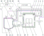
As shown in fig. 1, the preheating device for the engine and the battery according to the present embodiment improves the discharging capability of the battery in low temperature environments such as winter and increases the intake temperature of the diesel engine. As shown in fig. 1, the preheating device mainly comprises a thermal insulation box body 4 positioned on the right side and a reaction vessel 15 positioned on the left side, wherein a storage battery pack 8 is placed in the thermal insulation box body 4, and the thermal insulation box body 4 can protect the storage battery pack 8 from being exposed and directly frozen; the reaction vessel 15 can generate a large amount of heat energy by the reaction, heating the air inside thereof.
The heat preservation box 4 is connected with pipeline assembly, and pipeline assembly is including inlet line, outlet duct 18, and is specific, and the tonifying qi pipeline is installed to the upper left side of heat preservation box 4, and inlet duct is installed to the left downside, and outlet duct 18 is installed to the upper right side, and the preheating pipeline that admits air is installed to the lower right side. As shown in fig. 1, the air inlet duct and the air outlet duct 18 are connected to the reaction vessel 15, so that the air inlet duct communicates with the heat insulating box 4 and the reaction vessel 15, the air outlet duct 18 communicates with the heat insulating box 4 and the reaction vessel 15, and hot air generated after reaction in the reaction vessel 15 enters the heat insulating box 4 through the air inlet duct, so that the ambient temperature around the battery pack 8 is raised by the hot air, and the battery pack 8 can normally discharge even in an external low-temperature environment. When the temperature of the hot air in the heat preservation box body 4 is reduced to be cold air after heat exchange, the cold air flows into the reaction container 15 through the air outlet pipeline 18, so that the reaction container 15 is conveniently heated and utilized again, and circulation is realized.
It should be noted that, as shown in fig. 1, the connection position of the reaction vessel 15 and the air inlet pipe is lower than the connection position of the reaction vessel 15 and the air outlet pipe 18, so that the hot air generated by the reaction at the bottom of the reaction vessel 15 preferentially enters the air inlet pipe, and the design is reasonable.
The heat preservation box body 4 is also provided with an air supply pipeline and an air inlet preheating pipeline, and air can be supplemented into the heat preservation box body 4 from the outside through the air supply pipeline, and the air supply pipeline can also be used for balancing the air pressure inside and outside the heat preservation box body 4. The air inlet preheating pipeline is communicated with an air inlet (not shown in the figure) of the engine, so that hot air in the heat insulation box body 4 can enter the engine, the air suction temperature is increased, and the engine is normally started.
The top of the reaction vessel 15 is provided with an antifreeze liquid conveying pipeline and a quicklime particle conveying pipeline, the antifreeze liquid and the quicklime particles are conveyed into the reaction vessel 15 to be mixed, and the quicklime reacts after meeting water to release a large amount of heat so as to heat the air in the reaction vessel 15. The antifreeze can adopt a mixed solution of ethylene glycol and water, so that the condition that the antifreeze cannot be conveyed due to freezing is avoided. The granular quicklime is more convenient to convey in the pipeline and is reasonable in design. The pipe diameters of the antifreeze liquid conveying pipeline and the quicklime particle conveying pipeline can be determined by the feeding amount in unit time, the pipe diameter is large when the feeding amount in unit time is large, and the pipe diameter is small when the feeding amount in unit time is small.
When the anti-freezing liquid storage battery is used, the anti-freezing liquid conveying pipeline and the quicklime particle conveying pipeline are firstly opened, then the air inlet pipeline and the air outlet pipeline 18 are opened, the anti-freezing liquid and the quicklime particles enter the reaction container 15 to react, a large amount of heat is released, the temperature of the reaction container 15 is raised to generate hot air, and the hot air enters the heat insulation box body 4 from the air inlet pipeline, so that the ambient temperature around the storage battery 8 is raised, and the storage battery is enabled to normally discharge. When needed, the air inlet preheating pipeline can be opened, so that hot air can enter the engine, and the engine can be normally started. The hot air is changed into cold air after heat exchange in the heat insulation box body 4, and the cold air enters the reaction container 15 through the air outlet pipeline 18 to be reheated for recycling. If the air in the heat preservation box body 4 is insufficient, the air supply pipeline can be opened to supply air, or the air supply pipeline can be opened to balance air pressure when the pressure in the heat preservation box body 4 is too high, so that the use is safer. Therefore, the preheating device for the engine and the storage battery, provided by the embodiment of the invention, has the advantages of heating the storage battery and preheating the inlet air of the diesel engine, is safe to use and is suitable for popularization.
In some embodiments of the present invention, in order to better control the open/close state of each pipeline, as shown in fig. 1, the air inlet pipeline is provided with a first electric valve 10, the air outlet pipeline 18 is provided with a second electric valve 5, the air supply pipeline is provided with a third electric valve 20, the antifreeze liquid conveying pipeline is provided with a fourth electric valve 13, the quicklime particle conveying pipeline is provided with a fifth electric valve 16, and the air inlet preheating pipeline is provided with an electric control three-way valve 6. The opening and closing states of the respective ducts can be electrically controlled at any time by the first electric valve 10, the second electric valve 5, the third electric valve 20, the fourth electric valve 13, the fifth electric valve 16, and the like, and the use is very convenient. Two ports of the electric control three-way valve 6 are respectively connected with the air inlet preheating pipeline and the engine, the third port is connected with the outside air, when the environmental temperature is lower, the electric control three-way valve 6 is controlled to enable the heat preservation box body 4 to be communicated with the engine, and the port connected with the outside is closed, so that the engine sucks hot air and is smoothly ignited; when the ambient temperature is higher, the electric control three-way valve 6 is controlled to communicate the outside with the engine, the port of the air inlet preheating pipeline connected with the heat insulation box body 4 is closed, and the engine sucks the outside air to smoothly ignite.
In some embodiments of the present invention, the air inlet pipeline and the air outlet pipeline 18 are both provided with a dehumidifying structure 12, and the air inlet pipeline is also provided with a fan 11. As shown in fig. 1, the dehumidifying structure 12 is installed at a position where the air inlet duct (air outlet duct 18) is close to the reaction vessel 15, so as to prevent moisture in the reaction vessel 15 from entering the thermal insulation box 4 to cause a short circuit of the battery pack 8. The fan 11 is installed on the air inlet pipeline, and the fan 11 can enable air in the air inlet pipeline to flow directionally, so that hot air conveying is achieved.
Further, the dehumidifying structure 12 includes a dehumidifying box 122 and a box cover 121 detachably connected to each other, a non-woven air-permeable fabric 123 is disposed in the dehumidifying box 122, and a molecular sieve 124 is disposed between two layers of non-woven air-permeable fabric 123. As shown in fig. 2, a cavity is formed inside the dehumidifying box 122, and the internal cavity is communicated with the air outlet pipes 18 on two sides; left and right sides of dehumidification box 122 and lid 121 all are provided with the journal stirrup, and the journal stirrup of dehumidification box 122 and the journal stirrup of lid 121 aim at the coincidence, conveniently insert the screw. As shown in fig. 2 and 3, each two sheets of air-permeable non-woven fabric 123 and the molecular sieve 124 sandwiched therebetween form a dehumidifying unit, and one or more such dehumidifying units are disposed in the cavity of the dehumidifying box 122. When the dehumidifying box is used, air with moisture enters the cavity inside the dehumidifying box 122 from the air outlet pipeline 18, and the molecular sieve 124 absorbs the moisture to perform the dehumidifying function.
It should be noted that, after long-term use, the screws on the support lugs are unscrewed, the box cover 121 is opened, the dehumidifying unit inside the dehumidifying box 122 is taken out, then a new dehumidifying unit is put in, the box cover 121 is closed, the screws are screwed again, and the replacement is completed.
It should be noted that the dehumidification structure 12 on the intake duct is similar to the structure in fig. 2 and 3.
In some embodiments of the present invention, a battery fixing bracket 7 for accommodating a battery pack 8 is disposed in the thermal insulation box 4, and a wiring channel 9 is disposed on the surface of the thermal insulation box 4. As shown in fig. 1, the battery fixing bracket 7 can be fixed inside the thermal insulation box 4 by welding, and the storage battery 8 is buckled on the battery fixing bracket 7, so as to realize the fixed installation of the storage battery 8. Set up the wiring passageway 9 that runs through on the left side wall of insulation box 4, the cable of the storage battery 8 of being convenient for passes through wiring passageway 9 business turn over, and it is more convenient to use.
In some embodiments of the invention, the reaction vessel 15 comprises a V-shaped bottom surface provided with a waste discharge pipe provided with a sixth electric valve 14. As shown in fig. 1, the bottom of the reaction vessel 15 is provided with a V-shaped bottom surface, and the V-shaped bottom surface is in a funnel shape, so that waste materials after reaction can be conveniently collected. And a waste discharge pipe is arranged at the lowest part of the V-shaped bottom surface towards the vertical lower part, and a sixth electric valve 14 is arranged on the waste discharge pipe, so that the opening and closing states of the waste discharge pipe can be electrically controlled, and the use is convenient.
It should be noted that the mixture of antifreeze and quicklime particles does not flood the inlet or outlet pipes 18 and prevent clogging.
In some embodiments of the present invention, as shown in fig. 1, a cover 2 is disposed on the top of the thermal insulation case 4, and the cover 2 and the thermal insulation case 4 are connected by screws (the screws are illustrated in fig. 1). A sealing rubber pad 3 is arranged between the box cover 2 and the heat preservation box body 4, so that a good sealing effect is achieved, and hot air is prevented from leaking.
In some embodiments of the present invention, as shown in fig. 1, the outer surface of the insulation box 4 is wrapped by a first insulation layer 1, the first insulation layer 1 may be an aerogel insulation layer, the aerogel insulation layer is also called an aerogel felt, and the aerogel felt is a flexible insulation felt formed by combining nano-silica or metal aerogel as a main material with carbon fiber or ceramic glass fiber cotton or pre-oxidized fiber felt through a special process. It features low heat conductivity, certain tensile and compressive strength and is one new type of heat insulating material. The aerogel heat preservation parcel is lived insulation box 4, reduces calorific loss.
Furthermore, the outer surface of the reaction vessel 15 is wrapped with a second insulating layer, which also plays a role in reducing heat loss and reducing energy waste.
In some embodiments of the present invention, eight thermocouple temperature monitors are disposed at eight corners of the square-shaped thermal insulation box 4 for omni-directionally monitoring the ambient temperature inside the thermal insulation box 4. The embodiment is also provided with a temperature controller 19, the temperature controller 19 is provided with a thermocouple interface 17, and the thermocouple interface 17 is electrically connected with a thermocouple temperature monitor to realize temperature monitoring.
Referring to fig. 1, 2, 3 and 4, the control system includes a start control panel 21 and a temperature controller 19, wherein the temperature controller 19 is provided with a switch S1 and a switch S2, the switch S1 is electrically connected to the sixth electric valve 14, and the switch S2 is electrically connected to the first electric valve 10, the second electric valve 5, the third electric valve 20, the fourth electric valve 13, the fifth electric valve 16 and the fan 11 in parallel; the start control panel 21 is provided with a switch S3 and a switch S4, the switch S3 is electrically connected to the third electric valve 20, and the switch S4 is electrically connected to the electric three-way valve 6. The specific control and use principle is as follows:
start-up control panel 21: an air supply button and a cold start button are arranged, the switch S3 is closed after the air supply button is opened, the third electric valve 20 is opened, the outside starts to supply air into the heat preservation box body 4, the switch S3 is disconnected after the air supply button is closed, the third electric valve 20 is closed, and the outside stops supplying air into the box; after the cold start button is opened, the switch S4 is closed, the electric control three-way valve 6 is controlled to close the channel between the heat preservation box body 4 and the engine, the channel between the outside and the engine is opened, the switch S4 is disconnected after the cold start button is closed, the electric control three-way valve 6 is controlled to open the channel between the heat preservation box body 4 and the engine, and the channel between the outside and the engine is closed.
The temperature controller 19: through the inspection of a thermocouple temperature monitor, when the temperature of any measuring point in the heat preservation box body 4 is lower than a set temperature T1, the temperature controller 19 automatically controls the switch S1 to be disconnected and the switch S2 to be closed, the sixth electric valve 14 which is responsible for waste discharge is closed at the moment, the first electric valve 10, the second electric valve 5, the third electric valve 20, the fourth electric valve 13, the fifth electric valve 16 and the fan 11 which are connected in parallel are opened, and hot air is supplemented to the heat preservation box body 4 from the reaction container 15; when the temperature of all the measuring points in the heat preservation box body 4 is detected to be higher than the set temperature T2, the temperature controller 19 automatically controls the switch S1 to be closed and the switch S2 to be opened, at the moment, the sixth electric valve 14 which is responsible for discharging waste materials is opened, the first electric valve 10, the second electric valve 5, the third electric valve 20, the fourth electric valve 13, the fifth electric valve 16 and the fan 11 which are connected in parallel are closed, and the hot air supply is stopped.
In summary, the embodiment of the present invention provides a preheating device for an engine and a storage battery, the preheating device mainly includes a thermal insulation box 4 located on the right side and a reaction vessel 15 located on the left side, wherein a storage battery pack 8 is placed in the thermal insulation box 4, the reaction vessel 15 can generate a large amount of heat energy through reaction, an air supply pipeline is installed on the left upper side of the thermal insulation box 4, an air inlet pipeline is installed on the left lower side, an air outlet pipeline 18 is installed on the right upper side, an air inlet preheating pipeline is installed on the right lower side, an antifreeze conveying pipeline and a quicklime particle conveying pipeline are installed on the top of the reaction vessel 15, so that the discharge capacity of the storage battery in low temperature environments such as winter. For completely explaining the content of the invention, the air inlet pipeline is provided with a first electric valve 10, the air outlet pipeline 18 is provided with a second electric valve 5, the air supplementing pipeline is provided with a third electric valve 20, the antifreeze conveying pipeline is provided with a fourth electric valve 13, the quicklime particle conveying pipeline is provided with a fifth electric valve 16, and the air inlet preheating pipeline is provided with an electric control three-way valve 6 for respectively controlling the opening and closing states of the pipelines. The inlet duct and the outlet duct 18 are both provided with a dehumidifying structure 12, and the inlet duct is also provided with a fan 11, so that the use effect is better. The dehumidifying structure 12 comprises a dehumidifying box 122 and a box cover 121 which are detachably connected, a breathable non-woven fabric 123 is arranged in the dehumidifying box 122, a molecular sieve 124 is arranged between the two layers of breathable non-woven fabrics 123, and the dehumidifying structure is convenient to use and good in dehumidifying effect. A battery fixing bracket 7 for placing a storage battery pack 8 is arranged in the heat preservation box body 4, and a wiring channel 9 is formed in the surface of the heat preservation box body 4 to stably limit the storage battery pack 8. The reaction container 15 comprises a V-shaped bottom surface, a waste discharge pipe is arranged on the V-shaped bottom surface, and the waste discharge pipe is provided with a sixth electric valve 14. 4 tops of insulation box body are provided with case lid 2, are provided with sealed cushion 3 between case lid 2 and the insulation box body 4, and 4 surface coating of insulation box body has first heat preservation 1, and aerogel heat preservation can be selected to first heat preservation 1, and 15 surface coating of reaction vessel have the second heat preservation, and it is extravagant to reduce the energy. Eight thermocouple temperature monitors are arranged at eight corners in the square heat preservation box body 4, and the ambient temperature in the heat preservation box body 4 is monitored in all directions. Therefore, the preheating device for the engine and the storage battery has the advantages of heating the storage battery and preheating the inlet air of the diesel engine, is safe to use and is suitable for popularization.
The above is only a preferred embodiment of the present invention, and is not intended to limit the present invention, and various modifications and changes will occur to those skilled in the art. Any modification, equivalent replacement, or improvement made within the spirit and principle of the present invention should be included in the protection scope of the present invention.