The present application is a divisional application of an invention patent application entitled "modular connector and adapter apparatus", having an international application date of 2018, 1 and 29, international application number of PCT/US2018/015733, national application number of 201880005900.1.
Drawings
FIG. 1A is a perspective view of a prior art standard 6.25mm pitch LC connector SFP;
FIG. 1B is a perspective view of a prior art standard 6.25mm spacing LC adapter;
FIG. 1C is a top view of the prior art adapter of FIG. 1B;
FIG. 1D is a front view of the prior art adapter of FIG. 1B, showing a 6.25mm spacing;
fig. 2A is a perspective view of a prior art LC duplex connector;
fig. 2B is a perspective view of a prior art LC duplex connector with a remote release pull tab;
FIG. 2C is a top view of a prior art LC connector used in the embodiment shown in FIGS. 2A and 2B;
FIG. 2D is a side view of the prior art LC connector of FIG. 2C;
fig. 3 is a perspective view of a future narrow pitch LC SFP for receiving the connector disclosed herein, in accordance with aspects of the present disclosure;
FIG. 4A is a perspective view of one embodiment of a narrow pitch LC adapter according to aspects of the present disclosure;
FIG. 4B is a top view of the narrow pitch LC adapter of FIG. 4A;
FIG. 4C is a front view of the narrow pitch LC adapter of FIG. 4A, showing a 4.8mm pitch;
fig. 5 is a perspective view of one embodiment of a narrow pitch LC duplex connector with remote release, according to aspects of the present disclosure;
fig. 6A is a top view of an LC connector used in the embodiment of fig. 5, according to aspects of the present disclosure;
fig. 6B is a side view of the LC connector of fig. 6A, according to aspects of the present disclosure;
fig. 7 is a perspective view of the narrow pitch LC duplex connector of fig. 5 with the release mechanism removed, in accordance with aspects of the present disclosure;
fig. 8 is a perspective disassembled view of the narrow pitch LC duplex connector of fig. 5, in accordance with aspects of the present disclosure;
FIG. 9 is a perspective view of a standard prior art multi-fiber push-on/pull-off (MPO) SFP;
FIG. 10A is a perspective view of a prior art standard MPO connector;
FIG. 10B is a top view of the prior art MPO connector of FIG. 10A, the prior art MPO connector having a width of 12.4 mm;
FIG. 10C is a front view of the prior art MPO connector of FIG. 10A;
fig. 11 is a perspective view of a future narrow width multi-fiber SFP for receiving the connector disclosed herein, in accordance with aspects of the present disclosure;
fig. 12A is a perspective view of one embodiment of a narrow width multi-fiber connector (e.g., a female MPO connector) with remote release, according to aspects of the present disclosure;
fig. 12B is a top view of the narrow width multi-fiber connector of fig. 12A having a width of 9.6mm, in accordance with aspects of the present disclosure;
fig. 12C is a front view of the narrow width multi-fiber connector of fig. 12A, according to aspects of the present disclosure;
fig. 13A is a perspective view of a narrow-width multi-fiber connector inserted into a narrow-width SFP with an SFP latch, according to aspects of the present disclosure;
fig. 13B is a perspective view of a narrow-width multi-fiber connector inserted into a narrow-width adapter having an adapter latch, according to aspects of the present disclosure;
fig. 14 is a side view of the narrow width multi-fiber connector of fig. 13A having a recess engaged with the SFP latch in a normal tab position, in accordance with aspects of the present disclosure;
fig. 15 is a side view of the narrow width multi-fiber connector of fig. 13A disengaged from the SFP latch by retracting the pull tab, in accordance with aspects of the present disclosure;
fig. 16A is a perspective view of a narrow width multi-fiber connector with an adapter latch according to aspects of the present disclosure;
fig. 16B is a perspective disassembled view of a narrow width multi-fiber connector with an adapter latch according to aspects of the present disclosure;
FIG. 17A is a front view of the narrow pitch adapter of FIG. 16A, showing a pitch of 3.80 mm;
FIG. 17B is a side view of the narrow width connector of FIG. 16A;
FIG. 17C is a side view of a plug frame assembled within an SFP according to aspects of the present disclosure;
fig. 17D is a perspective view of the narrow width connector of fig. 16A with the push/pull tab in a normal position in the SFP latch recess, in accordance with aspects of the present disclosure;
fig. 17E is a perspective view of the narrow width connector of fig. 16A with the push/pull tab in a pulled position relative to the SFP latch recess, in accordance with aspects of the present disclosure;
fig. 18A is a perspective view of a small form factor transceiver in accordance with aspects of the present disclosure;
18B and 18C are respective side views of the transceiver of FIG. 18A, in accordance with aspects of the present disclosure;
FIG. 19 is a perspective view of an SFP with a connector inserted;
fig. 20A and 20B are side views of an SFP retaining connector according to aspects of the present disclosure;
FIG. 21 is a perspective view of an SFP with a connector inserted and the push/pull tab retracted, according to aspects of the present disclosure;
22A and 22B are side views of an SFP latch in a raised position to unlock a connector, according to aspects of the present disclosure;
fig. 23 is a perspective view of a connector inserted into an adapter according to aspects of the present disclosure;
24A and 24B are side views of the connector and adapter of FIG. 24 with the latch in the normal position;
FIG. 25 is a perspective view of a connector inserted into an adapter with a push/pull tab retracted according to aspects of the present disclosure;
26A and 26B are side views of the connector and adapter of FIG. 26 with the adapter latch in an unlocked position according to aspects of the present disclosure;
fig. 27A-27D are various embodiments of adapters and snap hooks for engaging connectors according to various aspects of the present disclosure;
fig. 28A is an exploded view of a connector according to aspects of the present disclosure;
fig. 28B is a perspective view of a connector according to aspects of the present disclosure;
FIG. 28C is a perspective view of the connector of FIG. 28B with a different push tab knob according to aspects of the present disclosure;
FIG. 28D is an exploded view of the connector of FIG. 28C;
fig. 28E is a bottom perspective view of the connector of fig. 28B and 28C, according to aspects of the present disclosure;
fig. 29A is a dimensional top view of a connector according to aspects of the present disclosure;
fig. 29B is a dimensional side view of a connector according to aspects of the present disclosure;
figure 30A is a perspective view of the connector with the push-pull tab in a forward position, according to aspects of the present disclosure;
figure 30B is a perspective view of the connector with the push-pull tab in the rearward position, according to aspects of the present disclosure;
figure 31A is a perspective view of a connector having a push-pull tab according to aspects of the present disclosure;
figure 31B is an enlarged perspective view of a connector having a push-pull tab according to aspects of the present disclosure;
figure 31C is another perspective view of a connector having a push-pull tab according to aspects of the present disclosure;
figure 32A is a perspective view of a connector having a push-pull tab according to aspects of the present disclosure;
figure 32B is an enlarged perspective view of a connector having a push-pull tab according to aspects of the present disclosure;
figure 32C is another perspective view of a connector having push-pull tabs according to aspects of the present disclosure;
FIG. 33A illustrates an exemplary CS connector according to some embodiments with two separate cross-sectional areas identified;
FIG. 33B is a detailed cross-sectional view of the CS connector at a first identified cross-sectional area of the CS connector identified in FIG. 28A;
FIG. 33C is a detailed cross-sectional view of the CS connector at a second identified cross-sectional area of the CS connector identified in FIG. 28A;
FIG. 34 is a perspective view of various connectors having push-pull tabs of different lengths in accordance with aspects of the present disclosure;
fig. 35A is a detailed dimensional front view of a duplex adapter/transceiver according to aspects of the present disclosure;
fig. 35B is a detailed dimensional cut-away view of a duplex adapter/transceiver according to aspects of the present disclosure;
fig. 35C is another detailed dimensional cut-away view of a duplex adapter/transceiver according to aspects of the present disclosure;
FIG. 36A is a perspective view of a duplex adapter/transceiver with a removable anchor installed;
FIG. 36B is a perspective view of a removable anchor device;
FIG. 36C is another perspective view of the removable anchor device;
FIG. 37A is another perspective view of the duplex adapter/transceiver with the removable anchor installed;
FIG. 37B is yet another perspective view of the removable anchor;
FIG. 37C is yet another perspective view of the removable anchor device;
FIG. 38A is yet another perspective view of the duplex adapter/transceiver with the removable anchor installed;
FIG. 38B is yet another perspective view of the removable anchor;
FIG. 38C is yet another perspective view of the removable anchor;
FIG. 39 is a detailed dimensional cut-away view of a duplex adapter/transceiver with a removable anchor installed in accordance with aspects of the present disclosure;
FIG. 40A is another detailed dimensional cut-away view of a duplex adapter/transceiver with a removable anchor installed in accordance with aspects of the present disclosure;
FIG. 40B is a detailed dimensional cut-away view of a duplex adapter/transceiver with a removable anchor installed in accordance with aspects of the present disclosure;
FIG. 40C is a perspective view of an adapter configured to receive a pull release connector with a hook positioned or inserted into the adapter, as shown in perspective and cross-sectional views;
FIG. 40D is a perspective and sectional view of the adapter hook prior to insertion of the adapter;
FIG. 40E is a perspective and cross-sectional view of the adapter hook partially inserted into the adapter;
FIG. 40F is a perspective and cross-sectional view of the adapter hook fully inserted into the adapter;
FIG. 41A is a perspective view of a CS connector inserted into an adapter/transceiver;
FIG. 41B is a perspective view of the CS connector after the adapter/transceiver is inserted;
FIG. 42A is a side cross-sectional view of the CS connector inserted into an adapter/transceiver;
FIG. 42B is a cross-sectional view of the adapter, as the pull release connector is inserted into the adapter via the hook;
FIG. 42C is a cross-sectional view of the pull release connector inserted into the adapter with the same details and the hook with a cross-sectional view;
FIG. 42D is a perspective view of the pull release connector of the pull tab rearward showing details of the hook middle region as it interacts with the pull tab recess of FIGS. 28D and 43 and the connector is released from the adapter housing;
FIG. 42E.1 is a cross-sectional view of a CS connector similar to FIG. 33 fully inserted into the adapter of FIG. 60;
FIG. 42E.2 is a cross-sectional view of a CS connector similar to FIG. 33 fully inserted into the adapter of FIG. 60;
fig. 42f.1 is a cross-sectional view of a CS connector similar to fig. 33, removed in the direction of the arrows;
fig. 42f.2 is a cross-sectional view of the CS connector similar to fig. 33, further removed in the direction of the arrows;
FIG. 42F.3 is a cross-sectional view of the CS connector similar to FIG. 33 released from the hook received in the adapter of FIG. 60;
FIG. 43 is a perspective view of a CS connector with a detailed view of a horizontal groove;
FIG. 44A is a side cross-sectional view of the CS connector inserted into an adapter/receiver;
FIG. 44B is another side cross-sectional view of the CS connector inserted into the adapter/receiver;
FIG. 45 shows an illustrative top view of a CS connector inserted into an adapter/receiver and a side cross-sectional view of the CS connector inserted into the adapter/receiver;
FIG. 46 shows an illustrative top view of a CS connector inserted into an adapter/receiver and a side cross-sectional view of the CS connector inserted into the adapter/receiver;
fig. 47 shows a detailed dimensional view of the CS connector;
FIG. 48 shows another dimensional detail view of the CS connector;
FIG. 49A illustrates a fan-out and box method for assigning connections to a slower version system;
FIG. 49B illustrates an alternative approach for distributing connections to a slower version system without the need for fanout and/or box methods.
Fig. 50A shows an exploded view of a pull-release type duplex connector with a dust cap;
FIG. 50B shows an assembled perspective view of FIG. 50A;
fig. 51A is a perspective view of a duplex (2-fiber) connector of the push/pull release type, wherein the pull tab housing is configured to engage the connector outer housing;
fig. 51B is a perspective view of a duplex (2-fiber) connector with a push/pull release type wall rear (BTW) guide, wherein the pull tab housing is configured to engage the connector outer housing;
FIG. 52A is an exploded view of the male MPO connector of FIG. 51B;
fig. 52B is an assembled view of the female MPO connector of fig. 51B;
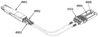
FIG. 52C is a perspective view of the MPO connector of FIG. 52B (on the left side of the adapter) and the male MPO connector of FIG. 52A (on the right side of the adapter) prior to insertion into the adapters;
FIG. 52D is a fully inserted view of the connector of FIG. 52C with the cross hatching indicating the hooks (FIG. 38B) engaging the latch recesses as shown in FIG. 42;
fig. 52E is a perspective view of an MT thin ferrule (ferule) for a compact, low-profile connector of the type shown in fig. 52B;
FIG. 53 is a perspective view of the push/pull tab and pull knob;
FIG. 54A is a top, side perspective and cross-sectional view of a curved latch push/pull compact low profile connector in an upward position;
FIG. 54B is a top perspective view of the curved latch push/pull type connector in a flush position;
FIG. 54C is a side perspective view of the curved latch push/pull type connector in an upward position;
FIG. 55A is a perspective view of the pull release connector prior to attachment of the pull tab to the connector body;
FIG. 55B is a perspective view of a push/pull tab attached to the connector body;
fig. 55C is a side perspective view of a push/pull tab attached to a connector body.
FIG. 56A is an exploded view of the CS connector, with the latch having a reinforced guide;
FIG. 56B is a top view of the assembled CS connector of FIG. 56A;
FIG. 56C is a side view of the assembled CS connector of FIG. 56A;
fig. 57A is an exploded view of a CS connector with a latch having a behind wall (BTW) guide;
FIG. 57B is a top view of the assembled CS connector of FIG. 57A;
FIG. 57C is a side view of the assembled CS connector of FIG. 57A, showing the direction of latch movement released from the adapter port housing (not shown);
FIG. 58A is an exploded view of an adapter having a flange that receives the hook of FIG. 36, FIG. 37, or FIG. 38 in a port of an adapter housing;
fig. 58B is a front perspective view of the adapter port of fig. 58A after receiving the hook of fig. 36, 37 or 38, showing the alignment sleeve retainer of fig. 60F configured to receive a push/pull type duplex connector;
FIG. 58C is a front view of an adapter port for receiving the MPO connector of FIG. 52, with hooks mounted for push/pull MPO type connectors;
fig. 58D is a top and side view of a push/pull CS connector with a BTW guide;
FIG. 59A is a perspective view of a low-profile duplex (2 fiber optic) adapter having a mounting flange for panel mounting with a hook inserted for receiving the push/pull type CS connector of FIG. 58D;
FIG. 59B is a perspective view of the low-profile duplex (2 fiber) flangeless adapter of FIG. 59A;
FIG. 59C is a perspective front view (top view) of the dual port (4 fiber) low profile adapter without the hook of FIG. 36, FIG. 37, or FIG. 38 installed and without the alignment sleeve retainer installed, and a front view (bottom view) after the hook is installed;
FIG. 59D is a perspective view of the CS connector of FIG. 53 released by pulling the tab in the direction of the arrow, and an enlarged view of the hook of FIG. 37 released from the recess of the connector of FIG. 53;
FIG. 59E is a perspective view of the CS connector of FIG. 53 released by pulling the tab in the direction of the arrow, and an enlarged view of the hook of FIG. 36 released from the recess of the connector of FIG. 53;
FIG. 59F is a perspective view of a low-profile dual port (4 fiber) adapter assembled with the adapter hook of FIG. 36, followed by the push/pull connector of FIG. 53 being inserted into the adapter port to allow the adapter to be converted from the latched type (FIG. 56) to the push/pull type (FIG. 53);
FIG. 59G is a perspective view of a low-profile dual port (4-fiber) adapter without the hooks of FIG. 36, FIG. 37, or FIG. 38, showing the insertion of a latch CS connector or a flex-latch CS connector into the adapter;
FIG. 59H is a perspective view of a low-profile dual port (4-fiber) adapter without hooks prior to insertion into a CS connector configured as a latching type;
FIG. 60A is an exploded view of a low-profile dual port (4-fiber) adapter having the hook of FIG. 26, FIG. 37, or FIG. 38;
FIG. 60B is a front perspective view of a low-profile dual port (4 fiber) adapter without the hook and inserted alignment sleeve holder of FIG. 60A;
FIG. 60C is a cross-sectional view and an exploded view of a port of a low-profile dual-port (4-fiber) adapter;
FIG. 60D is an enlarged view of the cross-sectional view of FIG. 60C with the sleeve inserted into the port of the adapter housing;
FIG. 60E is an enlarged view of the cross-sectional view of FIG. 60C with the sleeve inserted and the alignment sleeve retainer partially inserted into the adapter housing port;
FIG. 60F is an enlarged view of the cross-sectional view of FIG. 60C with the sleeve and alignment sleeve retainer fully inserted into the adapter housing port;
FIG. 60G is an enlarged view of FIG. 60F as seen from the bottom of the adapter;
FIG. 60H is an enlarged view showing the cutout of the alignment sleeve retainer fully inserted into the port of the adapter housing;
FIG. 61A is a side perspective view of a flanged, two-port (4 fiber) low-profile adapter;
FIG. 61B is a side perspective view of a flangeless, two port (4 fiber) low profile adapter;
FIG. 61C is a front perspective view of a dual port (4 fiber) low profile adapter with a hook inserted therein and a top view thereof;
FIG. 62A is an enlarged view just prior to insertion of a latch-type connector (e.g., FIG. 56 or FIG. 57) into a duplex (2-fiber) low-profile adapter housing port without hooks;
FIG. 62B is an enlarged view showing the structural contact points within the adapter housing that engage the latch-type connector (e.g., FIG. 56 or FIG. 57);
FIG. 62C is an enlarged side view showing the latch-type connector partially inserted into a duplex (2-fiber) low-profile adapter housing port without a hook;
FIG. 62D is an enlarged bottom view showing the latch-type connector partially inserted into a duplex (2-fiber) low-profile adapter housing port without hooks;
FIG. 62E is an enlarged top side view showing the latch-type connector fully inserted into a duplex (2-fiber) low-profile adapter housing port without a hook;
FIG. 62F is an enlarged bottom side view showing the latch-type connector fully inserted into a duplex (2-fiber) low-profile adapter housing port without a hook;
FIG. 62G is a cross-sectional view of the latch-type CS connector similar to FIG. 56 fully inserted into the adapter of FIG. 60;
FIG. 62H is the cross-sectional view of FIG. 62G with the connector latch pressurized in the direction of the arrow to release from the adapter port;
FIG. 62I is the cross-sectional view of FIG. 62H with the connector pulled in the direction of the arrows to complete the release from the adapter port;
FIG. 63A is a perspective view prior to insertion of the latch-type connector into either side of a duplex (2-fiber) low-profile adapter;
FIG. 63B is a perspective view of the latch type connector fully inserted into both sides of a duplex (2 fiber) low profile adapter;
FIG. 63C is a series of enlarged views of the connector of the latch (e.g., FIG. 57) pressed prior to and during removal of the connector from the adapter housing in the direction of the arrow without the hook;
FIG. 64A is a perspective view of a dual (4 fiber) low profile adapter housing without hooks on either side prior to insertion of two duplex latch type (e.g., FIG. 57) connectors;
FIG. 64B is a perspective view after insertion of two duplex latch-type (e.g., FIG. 57) connectors on either side of a dual (4-fiber) low-profile adapter housing without hooks;
fig. 65A is a perspective view before insertion of the low-profile duplex (2-fiber) adapter housing of the crimp guide latch-type connector into the first port and insertion of the rear wall (BTW) latch-type connector into the second port;
fig. 65B is a perspective view after insertion of the low-profile duplex (2-fiber) adapter housing of the crimp guide latch-type connector into the first port and insertion of the wall rear (BTW) latch-type connector into the second port;
FIG. 66A is a perspective view of a duplex (2 fiber) adapter without flanges, the duplex (2 fiber) adapter without flanges being configured at a first adapter port with hooks and configured at a second adapter port without hooks;
FIG. 66B is a perspective view of the adapter of FIG. 66A with the latch type connector inserted into the second adapter port and the push/pull type connector inserted into the first adapter port;
FIG. 67A is a perspective view of a dual port (4 fiber) adapter without flanges, the dual port (4 fiber) adapter being configured at a first adapter port with hooks and a second adapter port without hooks;
FIG. 67B is a perspective view of a dual port (4 fiber) adapter with a push/pull connector inserted into the first adapter port and a latch-type connector inserted into the second adapter port;
FIG. 68A is a perspective view of a duplex (2-fiber) adapter having a flange and a latch-type connector inserted into a first port of the low-profile adapter and a push/pull-type connector inserted into a second port of the low-profile adapter;
FIG. 68B is a perspective view of a dual (4-fiber) adapter with a flange and two latch-type connectors plugged into one side of the low-profile adapter and two push/pull-type connectors plugged into the second port of the low-profile adapter;
FIG. 69A is a side, front and top view of a tool for removing a hook from an adapter housing port;
FIG. 69B is a perspective view of the tool of FIG. 69A connected to the hook of FIGS. 36, 37 and 38;
FIG. 70A is a cross-sectional and perspective view of the tool of FIG. 69A attached to a hook inserted into a port of an adapter housing;
FIG. 70B is a cross-sectional and perspective view of the tool of FIG. 69A attached to a hook partially removed from an adapter housing port; and
fig. 70C is a cross-sectional and perspective view of the tool of fig. 69A attached to a hook completely removed from an adapter housing port.
Detailed Description
The present disclosure is not limited to the particular systems, devices, and methods described, as these may vary. The terminology used in the description is for the purpose of describing the particular versions or embodiments only and is not intended to limit the scope.
As used in this document, the singular forms "a," "an," and "the" include plural referents unless the context clearly dictates otherwise. Unless defined otherwise, all technical and scientific terms used herein have the same meaning as commonly understood by one of ordinary skill in the art. Nothing in this disclosure should be construed as an admission that the embodiments described in this disclosure are not entitled to antedate such disclosure by virtue of prior invention. As used in this document, the term "including" means "including but not limited to".
For the purposes of this application, the following terms shall have the corresponding meanings set forth below.
As used herein, a connector refers to a device and/or components thereof that connects a first module or cable to a second module or cable. The connector may be configured for optical fiber transmission or electrical signal transmission. The connector may be of any suitable type now known or later developed, such as a Ferrule Connector (FC), a Fiber Distributed Data Interface (FDDI) connector, an LC connector, a Mechanical Transport (MT) connector, a Square Connector (SC) connector, an SC duplex connector or a Straight (ST) connector. The connector may generally be defined by a connector housing body. In certain embodiments, the housing body may contain any or all of the components described herein.
"fiber optic cable" or "fiber optic cable" refers to a fiber optic cable comprising one or more optical fibers for conducting optical signals in an optical beam. The optical fibers may be constructed of any suitable transparent material, including glass, fiberglass, and plastic. The cable may include a jacket or sheath material surrounding the optical fibers. Further, the cable may be connected to the connector on one end or both ends of the cable.
Various embodiments described herein generally provide a remote release mechanism such that a user can remove cable assembly connectors that are closely spaced together on a high density panel without damaging surrounding connectors, without accidentally disconnecting surrounding connectors, without disrupting transmissions through surrounding connectors, and/or the like. Various embodiments also provide for use of narrow pitch LC duplex connectors and narrow width multi-fiber connectors; such as future narrow pitch LC SFP and future narrow width SFP. The remote release mechanism allows the use of narrow pitch LC duplex connectors and narrow width multi-fiber connectors in a dense array of narrow pitch LC SFPs and narrow width multi-fiber SFPs.
Fig. 1A shows a perspective view of a prior art standard 6.25mm pitch LC connector SFP 100. SFP 100 is configured to receive duplex connectors and provides two ports 102, each for receiving a respective LC connector. The pitch 104 is defined as the axis-to-axis distance between the central longitudinal axes of each of the two ports 102. Fig. 1B shows a perspective view of a prior art standard 6.25mm pitch LC adapter 106. The adapter 106 is also configured to receive duplex connectors and provide two ports 108, each for receiving a respective LC connector. Fig. 1C is a top view of the adapter 106 of fig. 1B. The pitch of the adapters 106 is defined as the axis-to-axis distance between the central longitudinal axis of each of the two ports 108, similar to the pitch of the SFPs 100, as shown in fig. 1D, which shows a front view of the adapters 106.
Fig. 2A illustrates a prior art LC duplex connector 200 that may be used with a conventional SFP 100 and a conventional adapter 106. The LC duplex connector 200 includes two conventional LC connectors 202. Fig. 2B shows another prior art LC duplex connector 204 having a remote release pull tab 206 and including two conventional LC connectors 208. As shown, the remote release pull tab includes two prongs 210, each prong 210 configured to couple to an extension member 212 of a respective LC connector 208. Fig. 2C and 2D show a top view and a side view, respectively, of a conventional LC connector 208 having a width of 5.6mm, and also show an extension member 212.
Various embodiments disclosed herein are configured for use with future SFPs, such as narrow pitch LC SFP 300 shown in fig. 3, which has a pitch that is smaller than conventional 6.25mm and 5.25mm pitches. Various embodiments use LC-type fiber optic connectors in a duplex arrangement (with transmit and receive fibers), but the axis-to-axis distance of the connectors is less than the conventional 6.25mm and 5.25mm pitch, as described further below.
According to another aspect, embodiments of a narrow pitch duplex LC adapter are disclosed. Fig. 4A-4C illustrate an embodiment of a narrow pitch adapter 400. The narrow pitch adapter 400 has ports 402 on opposite ends thereof that are configured for engagement with two narrow pitch LC duplex connectors according to aspects disclosed herein. Fig. 4B shows a top view of adapter 400. Fig. 4C shows a front view, further illustrating that adapter 400 has a pitch of 4.8 mm. The adapter 400 is configured to receive duplex LC connectors with a pitch corresponding to the axis-to-axis distance between the LC connectors of the LC duplex connectors. Although adapter 400 has a pitch of 4.8mm, various embodiments of the narrow pitch adapters disclosed herein may have a different pitch that is smaller than the pitch of conventional adapters, e.g., less than 6.25mm and less than about 5.25 mm. In certain embodiments, the spacing may be about 4.8mm or less.
In addition to the need for narrow connectors, remote unlocking of narrow connectors used in dense narrow SFP arrays is also required. This is because it is almost impossible to reach the connector with a finger without disrupting the service of the adjacent fibers. While current designs for remotely unlocking fiber optic connectors exist, as shown, for example, in fig. 2B, they have proven difficult to function as desired when plugged into the typical diecast structure as all SFPs. Die-cast SFPs are never free of sharp edges and internal flashing (burrs) that can interfere with the normal flexing movement of the plastic latch of the fiber optic connector. Interference between the metal edge and the burr prevents the plastic latch of the fiber optic connector from becoming fully engaged or easily disengaged, especially for latches that are remotely triggered by a pull tab that protrudes a distance behind the connector, thereby preventing fingers from interfering with adjacent optical fibers.
To make latching/unlatching of the connector from the SFP more reliable, various embodiments disclosed herein add a spring force to the remote latching component (pull tab), e.g., as shown and described below with reference to fig. 5, 7, 8, and 12, to ensure that the connector latch is allowed to return to the un-displaced position and thereby become fully engaged within the groove of the SFP.
Fig. 5 illustrates one embodiment of a narrow pitch connector 500 in accordance with aspects disclosed herein. The narrow pitch connector 500 is a duplex LC connector comprising two LC connectors 502. Each of the LC connectors 502 includes a respective ferrule 503 and a respective extension member or latch arm 504. The connector 500 has a pitch of 4.8mm, which is defined as the axis-to-axis distance between the center axes of the LC connectors 502. In other embodiments, the connector pitch may be less than that of conventional connectors, for example, less than 6.25mm, and less than about 5.25 mm. In certain embodiments, the spacing may be about 4.8mm or less.
The connector 500 also includes a housing 506, the housing 506 having a bottom housing 508 and a top housing 510. The bottom housing 508 includes a sidewall 512. In various embodiments, housing 506 of connector 500 may be a switchable housing. The side walls 512 may be configured to open to facilitate opening the housing 506, for example, to change the polarity of the connector 500. The side walls 512 may be raised toward the rear of the connector 500, as shown in fig. 5. One advantage of raising the side walls 512 toward the rear of the connector 500 is easier access. In other embodiments, the sidewall 512 may be raised at another location.
Connector 500 also includes pull tab 514 having distal end 516 and proximal end 518. The pull tab 514 also includes a spring 520 configured to provide a force such that the connector latch arm 504 returns to an un-displaced position and thereby becomes fully engaged within the recess of the SFP. The distal end 516 of the pull tab 514 may be pulled (e.g., in the direction of the arrow shown in fig. 7) to remotely release the connector 500 from the SFP or adapter. The proximal end 518 of the pull tab 514 has a unique shape to engage with the unique profile of the latch arm 504 of the narrow pitch LC connector 500. The proximal end 518 engages both latch arms 504 of the duplex LC connector 500. That is, the proximal end 518 includes a single prong configured to engage the latch arms of both connectors 502. At the proximal end 518 of the pull tab 514, there is an outwardly directed pin 522 configured to rest directly above and slide along the semi-circular surface of the latch arm 504 of the duplex LC connector 502. The horizontal and rearward path directions of latch arms 522 cause the semi-circular profile of connector latch arms 504 to curve downward. Because the pin 522 is not received within the angled groove of the connector latch arm 504, the pull tab 514 may also be pushed downward at a location directly behind the LC connector 502, rather than pulling the tab in a rearward motion from a remote distance behind the connector, such as from the distal end 516. The action of pushing the connector's integral lever or latch arm 504 downward unlocks the connector 500. In some cases, horizontal movement of pull tab 514 may be undesirable. Thus, connector latch arm 504 can be pushed downward without causing horizontal movement of pull tab 514.
Fig. 6A and 6B show top and side views, respectively, of an LC connector 502 of the narrow pitch connector 500. Fig. 6A further illustrates that the LC connector 502 has a width of 4.6 mm. Fig. 6B shows a semi-circular profile of the latch arm 504.
Fig. 7 shows a partially disassembled view of the narrow pitch connector 500 of fig. 5. The top housing 510 is separate from the bottom housing 508. Pull tab 514 is coupled to top housing 510 and is configured to slide longitudinally along the length of the connector. The top housing 510 also includes a restraint 524, the restraint 524 configured to receive the pull tab 514.
Fig. 8 shows a further disassembled view of the narrow pitch connector 500. Specifically, pull tab 514 is shown separated from top housing 510 and spring 520 is removed from the pull tab. The pull tab 514 includes a longitudinal recess 526 configured to receive the spring 520 and at least one restraint 528 configured to retain the spring. Top housing 510 also includes a recess 530, which recess 530 is configured to receive at least a portion of pull tab 514, e.g., spring 520 and proximal end 518. In various embodiments, the pull tab may be removably coupled to the connector via the top housing.
FIG. 9 shows a perspective view of a prior art standard MPO SFP 900. The SFP 900 is configured to receive standard MPO connectors and provide ports 902 for receiving MPO connectors having conventional widths, as shown, for example, in fig. 10A through 10C.
Fig. 10A shows a perspective view of a conventional MPO connector 1000. As shown in fig. 10B, the conventional MPO connector 1000 has a width of 12.4 mm. Fig. 10C shows a front view of the MPO connector 1000.
Fig. 11 illustrates an embodiment of a future narrow width multi-fiber SFP 1100 in accordance with aspects of the present disclosure. Various embodiments disclosed herein are configured for use with narrow-width multi-fiber SFPs 1100, the width of the narrow-width multi-fiber SFP 1100 being less than the width of a conventional MPO connector, less than about 12.4 mm. A narrow width multi-fiber SFP has a port 1102 that is configured to receive a narrow width multi-fiber connector, such as a narrow width connector with an MT ferrule (e.g., shown in fig. 12A).
Fig. 12A illustrates one embodiment of a narrow width connector 1200 in accordance with aspects disclosed herein. The narrow width connector 1200 is a multi-fiber connector that includes a multi-fiber MT/MPO ferrule 1202. The connector 1200 includes two extension members or latch arms 1204. In other embodiments, the connector may include at least one latch arm. The connector 1200 has a width of 9.6mm as shown in the top view of the connector 1200 in fig. 12B. In other embodiments, the connector width may be less than the width of a conventional multi-fiber connector, for example, less than 12.4mm of the conventional MPO connector shown in fig. 10B. In certain embodiments, the width may be about 9.6mm or less.
Connector 1200 also includes a housing 1206 having a bottom housing 1208 and a top housing 1210. Bottom housing 1208 includes a sidewall 1212. In various embodiments, the housing 1206 of the connector 1200 may be a switchable housing. The side walls 1212 may be configured to open to facilitate opening of the housing 1206, e.g., to change the polarity of the connector 1200. The sidewalls 1212 may be raised toward the rear of the connector 1200. One advantage of raising the side walls 1212 toward the rear of the connector 1200 is easier access. The sidewall 1212 may also be raised at another location.
Connector 1200 also includes pull tab 1214 having a distal end 1216 and a proximal end 1218. The pull tab 1214 further includes a spring 1220, the spring 1220 configured to provide a force such that the connector latch arm 1204 returns to an un-displaced position and thereby becomes fully engaged within the groove of the SFP. The distal end 1216 of the pull tab 1214 may be pulled to remotely release the connector 1200 from the SFP or adapter. The proximal end 1218 of the pull tab 1214 has a unique shape to engage with a unique profile of the latch arm 1204 of the narrow width multi-fiber connector 1200. The proximal end 1218 engages the two latch arms 1204 of the multi-fiber connector 1200. That is, the proximal end 1218 includes a single prong configured to engage the latch arm 1204. At the proximal end 1218 of the pull tab 1214, there is an outwardly directed pin 1222 that is configured to rest directly above and slide along the semi-circular surface of the latch arm 1204. The horizontal and rearward path directions of the pin 1222 cause the semi-circular profile of the connector latch arm 1204 to bend downward. Because the pin 1222 is not received within the angled recess of the connector latch arm 1204, the pull tab 1214 may also be pushed downward at a location directly behind the latch arm 1204, rather than pulling the tab in a rearward motion from a remote distance behind the connector, such as from the distal end 1216. The action of pushing the connector's integral lever or latch arm 1204 downward unlocks the connector 1200. In some cases, horizontal movement of the pull tab 1214 may be undesirable. Thus, the connector latch arm 1204 may be pushed downward without causing horizontal movement of the pull tab 1214.
Fig. 12B and 12C show a top view and a front view, respectively, of the narrow width multi-fiber connector 1200. Fig. 12B also shows that connector 1200 has a width of 9.6 mm.
In the various embodiments described above, the narrow width connector has latch arms configured to engage with fixed or non-movable grooves within the narrow width SFP or narrow width adapter. In these embodiments, the pull tab of the connector displaces the flexible latch arm of the connector, thereby disengaging the latch arm from the recess of the SFP or adapter. For example, as the pull tab is pulled back, the latch arm flexes downward to disengage the connector from the SFP or adapter.
In other embodiments, the remote latch release pull tab may be configured to couple with a latch or hook within an adapter or SFP, as further described, for example, below with reference to fig. 13A, 13B, 14, and 15. In these embodiments, the flexible latch arms of the connector move into the main cavity or port of the SFP or adapter, and the latches of the SFP or adapter engage the recesses of the connector when the pull tab, pushed forward by the spring, is in the normal position. The pull tab may be configured with a ramp area such that when the pull tab is pulled back, the SFP or adapter latch is lifted by the retracted pull tab, thereby disengaging the SFP or adapter latch from the connector. In an attempt to pull the connector 1300 body rather than the pull tab, the SFP latch holds the connector within the adapter, as shown in fig. 14.
Fig. 13A shows a narrow pitch multi-fiber connector 1300 inserted into a narrow pitch SFP 1302 such that the recess of the connector engages SFP latch 1402. Fig. 13B shows the narrow pitch connector 1300 inserted into the narrow pitch adapter 1304 such that the recess of the connector engages the latch 1402 of the adapter.
Fig. 14 shows a side view of the narrow-width connector 1300 of fig. 13A coupled to a narrow-width SFP 1302. Details of the coupling are shown within circle 1400. In particular, SFP 1302 includes SFP latch 1402. The connector 1300 includes a recess 1404. For example, the connector housing may include a recess 1404 on one side. The pull tab 1406 may be spring loaded as described with respect to various embodiments. This allows the pull tab 1406 to return to a position that will allow the SFP latch 1402 to engage with the connector recess 1404. When the pull tab 1406, which is pushed forward by the spring, is in the normal pull tab position, as shown in fig. 14, the SFP latch 1402 engages the connector recess 1404.
Fig. 15 shows a side view of the narrow width connector 1300 of fig. 13A as the narrow width connector 1300 is disengaged from the narrow width SFP 1302. Details of decoupling are shown within circle 1500. The pull tab 1406 includes a tapered or beveled region 1502. As the pull tab 1406 is pulled back as shown in the direction of arrow 1504, the SFP latch 1402 lifts by the ramp region 1502 of the retracted pull tab, thereby disengaging the SFP latch 1402 from the connector, as shown in circle 1500. The same effects described in connection with fig. 15 also occur in other embodiments of connectors coupled to narrow width adapters, as shown, for example, in fig. 13A.
Although fig. 14 and 15 illustrate the coupling of a connector to a narrow width SFP, in other embodiments, a connector may be coupled to a narrow width adapter having an adapter latch similar to the adapter latch of the SFP latch. Further, while the embodiments shown in fig. 13A, 13B, 14, and 15 include narrow width multi-fiber connectors, other embodiments herein may include narrow pitch LC connectors.
As noted above, the embodiment of fig. 14 and 15 shows an improvement over the prior art adapter (fig. 1) and connector (fig. 2). The improvement is in the areas of the latch 1402 and recess 1404 when the connector is fully inserted into an adapter or transceiver port. Unless the pull tab 1406 is retracted 1504, the latch 1404 holds the connector within the ports 1302, 1304, 1400 (as shown in fig. 13 and 14) to an acceptable pull force. Further embodiments of the present invention improve pull strength, stability of the connector in the port, and connector alignment when inserted into the port with improvements to the port interface and connector release mechanism.
Referring briefly to fig. 49, the connectors may be bundled or clustered with different lengths of cable between the connectors. The cables become entangled and can be pulled by trained users. The pulling force loosens the connector within the port. If the pulling force is greater than the locking force, the connector may become dislodged or at least the interface between the connector fiber optic pathway and the optical-to-electrical interface may become misaligned, resulting in signal loss. The connectors are also placed in the panel via adapters similar to the adapter of fig. 40, with two connectors having interfaces or wires. Wiring occurs when a first connector is inserted into a first port and a second connector is inserted into a second port. Unlike plugging into a transceiver, aligning the fiber path between opposing connectors along the x-y axis is directly related to the quality of the signal path.
Thus, determining a defective connector interface in a room of thousands of connectors can be time consuming and is typically not detected. Also, as connector sizes decrease, access to release the connector becomes problematic for the user. Further, the connector may be used behind a wall or behind a panel (e.g., the connector is not directly accessible to a user) as opposed to a front patch connector. Compare fig. 56 and fig. 57 for examples of different connector types. The release mechanism is different due to the structural differences between the front and BTW types. But the port interfaces are the same. The present invention helps to improve connection stability, alignment of the connector with the connector, and ease of release.
Fig. 16A-22 are various views and details showing a connector, SFP transceiver and latch mechanism associated therewith according to various aspects of a first embodiment of the present invention. Referring to fig. 16, the connector 1600 is a front patch type connector with a removable push/pull tab 1601. Proximal end 1640 of connector 1600 is located at the end of plug frame 1609 and distal end 1650 of connector 1600 is located at the end of guide 1602. The recess 1614 receives the latch 1402 and the spring 1610 urges the tab 1601 forward. The guide 1602 is a reinforced round cable that is typically found on front type connectors used in patch panels or plugged into transceiver ports. The push-pull tabs are anchored to the connector body by side tabs 1613, which side tabs 1613 are press-fit onto the back body 1604 of the connector 1600.
Referring to fig. 17, the connector 1600 is sized to show a reduced size plug frame 1609 for a narrow pitch connector. Referring to FIG. 17A, the ferrule spacing or distance between ferrules is approximately 3.80mm, while the overall outside dimension is 7.85mm wide and 8.18mm high. These dimensions are required by industry standards of all connector manufacturers. As connector sizes decrease, the available external area for securing the connector within the port also decreases. Despite the reduced size of the ports and connectors, performance in terms of limited signal loss, pull strength, and connector/port stability is not degraded.
With the present invention, a port is an opening that receives the proximal end of a connector or interface device (e.g., a computer card), and the port contains structure therein to secure and stabilize the connector and further ensure alignment of the opposing fiber optic signal paths. The adapter includes one or more ports (e.g., as shown in fig. 40 or 60) that may be present for a patch panel or transceiver as shown in fig. 18.
Referring to fig. 17D-17E, the operation of the push/pull tab is shown. In fig. 17D, tab 1601 is in its normal proximal position, urged forward by spring 1610. This positions the latch release 1712 in a proximal position relative to the recess 1710. The ramp 1720 assists in lifting the latch as described herein. In fig. 17E, the user pulls the tab 1601 in the direction of the arrow and the latch release 1712 moves forward to engage the latch 1402 (not shown) and lift the latch out of the recess 1710, which releases the connector from the port interface.
Referring to fig. 18, a transceiver 1800 is shown with a flexing latch 1820 inserted at the proximal end 1810 of the duplex transceiver 1800. The flex latch 1820 is an interface structure within the port that secures the connector 1700 (not shown) therein. Fig. 18C shows the flexed latch 1820 at cross-section a-a of fig. 18B.
Referring to fig. 19, the connector 1700 is inserted into a port of a duplex transceiver 1900. Fig. 20A shows the flexing latch 1820 positioned in the connector recess 1710 at cross-section B-B of fig. 20B. Fig. 20A differs from fig. 14 as both show a connector secured within a port using a latch 1820. When the latch is positioned in the recess, the pull tab is biased forward by the spring.
Fig. 21 and 22 show the connector removed from the transceiver 1900 in the direction of the arrow of fig. 21. Referring to fig. 22A, a ramp 2220 on the push/pull tab (see fig. 17) lifts flex latch 2210 to unlock connector 1700 from within the port. Fig. 22A is a cross-section B-B of fig. 22B.
Fig. 23-24 illustrate the operation of connector 1700 using an adapter that is typically deployed in a patch cord system having a latching mechanism similar to that of fig. 14, and which is similar to the receiver of fig. 19-22. Fig. 23-24 show a connector 1700 inserted into a port of an adapter 2300. The latch 1820 resides in the connector recess 1710. Fig. 25 to 26 show the same operation as that described in fig. 21 to 22 to release the connector 1700 from the port of the adapter in this case. The adapter port can also accommodate a flexible latch 1820, as with the transceiver port of fig. 20A.
Referring to fig. 27, the adapter 2300 of fig. 23 can have a flexible latch 2780 that is inserted into each port of the adapter 2700, as shown in fig. 27B. Fig. 27C is a sectional view a-a of fig. 27D. Fig. 27C shows a flexible latch 2780 that engages the support track as shown and press fits 2790 into the adapter body to secure the latch against displacement when inserting and removing the connector. Similar press-fit structures may be used in the transceiver ports. When the outer dimensions of the flexible latch 2780 are slightly larger than the inner port, the press-fit structure helps to retain the flexible latch in the port, so friction between the latch and the port support rail retains the latch 2780 when the latch 2780 is inserted.
The embodiments disclosed in fig. 14-27 suffer from a number of disadvantages that are overcome by the additional embodiments disclosed herein. The latches 1402, 1820 and the recess 1710 have a limited pulling force in excess, which can result in the removal of the connector from the port. Also at the connector, front portion 1614 may be expelled from opening 1675 under stress at the connector or its wiring, and connector front portion 1614 will become wedged or stuck in the port. Also, the latch recess 1712 does not fully secure the latch 1820 therein, and stress on the connector body or its wiring can dislodge the latch, wherein the connector becomes loose in the port, which is visually undetectable. This can result in signal loss when the interconnect is broken. The latch and recess also have movement that can cause misalignment of the opposing fiber optic signal paths. As shown in fig. 17E and 18C, the hooks on the curved latches can slide widthwise in the recesses 1614 of the connector 1600. In addition, the flexible latch is press fit into the port which may be dislodged or misaligned under sufficient tension, which may prevent insertion of the connector into the port. Further, as the overall size (e.g., outer, inner, and length dimensions) of the connector and port are reduced, the number of exposed structures is reduced to secure and align the connector. Since connectors are made primarily of plastic for cost reasons and plastic fails more frequently than metal, and since testing is standardized, more innovative designs are needed to maintain the same performance as metal, such as smaller plastic parts and having lower structural integrity.
Fig. 23-27D illustrate various views and details showing a narrow pitch multi-fiber connector engaged and disengaged with an adapter port. The connector and adapter include latching mechanisms designed and arranged to be latched and unlatched, for example, using push/pull tabs positioned on the connector body.
As discussed herein, structural improvements are needed to reduce connector and adapter (and also transceiver size) and incorporate new release mechanism and guide designs to meet various industrial environments. Referring now to fig. 28A, an embodiment of the improved narrow pitch or CS connector is shown exploded for detail. It should be noted that this visual example is for explanatory purposes and that various alternative examples may exist, some of which are discussed herein. In some embodiments, the CS connector may be a micro unit position plug, generally characterized by a double cylindrical, spring-loaded one or more mating ferrules and a push-pull coupling mechanism of about 1.25mm diameter.
In certain embodiments, the CS connector may include a front body (i.e., plug frame) 2801 that houses one or more ferrules and one or more ferrule flanges 2802. A rear body (i.e., rear post) 2804 may be connected to the rear of the front body 2801 and contain one or more ferrule flanges 2802. One or more ferrule flanges 2802 may be held in place using one or more springs 2803. As shown, the rear body 2804 can include a crimp ring 2805 attached to the rear of the rear body. In certain embodiments, the cable guide 2806 may surround the crimp ring 2805. In certain embodiments, and as shown, a dust cap 2807 may be placed on the front body 2801 to protect a ferrule housed in the front body from damage and/or debris.
In additional embodiments, the push-pull tab 2810 may be attached to a CS connector as discussed in more detail herein. The push tab 2810 can have side portions 2812 and a central protrusion (i.e., 2813b) that serves to anchor the pull tab and other functions discussed further herein. The push pull tab 2810 can utilize a tab spring 2808 to exert a constant directional force on the push pull tab to allow for the various benefits discussed herein. The push-pull tab 2810 can have a transverse recess 2817 and a multi-sloped ramp region 2820 that engages with an anchoring device to help ensure repeatable release and connection of the connector within the port.
Referring briefly to fig. 28B, one embodiment of an assembled CS connector with push-pull tabs is shown. In certain embodiments, and as shown, the push-pull tab 2810 has a front portion 2814, the front portion 2814 residing in a longitudinal recess 2875 within the front body 2801. Thus, as the push-pull tab 2810 traverses the connector, the front portion 2814 moves independently of the front body 2801 as discussed in detail herein. The side portion 2812 is one anchoring point for anchoring the push-pull tab 2810 to the connector 2800C. The anchor points 2813d are extended tabs that extend from the side portions 2812 below the rear body 2804.
Figure 28C is a perspective view of a low profile compact connector having a standard push-pull tab release with a reinforced round cable. In certain embodiments, the compact connector 2800C may include a dust cap 2840C, one or more ferrules 2850C, a connector housing 2810C, a push-pull tab 2820C, one or more ears 2825C, and a reinforced round cable 2830C. The ears 2825C extend below the posterior body and serve as anchor points 2813d, as shown in fig. 28E. The ears help prevent inadvertent removal of the push-pull tab by popping out during use, and the ears also help guide the push-pull tab along the connector housing.
Referring to FIG. 28D, the push-pull tab 2823 is a modification of the push/pull tab 1604. The push-pull tab 2823 has three additional anchor points 2813a, 2813b, and 2813 c. The anchor point 2813a has a protrusion 2813a or tongue that extends perpendicularly into the recess 2875 and provides stability to the proximal end of the push-pull tab, which shows a tendency to jump out of the recess 2875 at the front portion 2814 when the force on the push-pull tab at the distal end is excessive. The front portion engagement surface 2815 engages the port inner surface to help align the connector therein. Anchor points 2813B are shown in fig. 32B, 32C, and 33B. A second anchor point 2813C is shown in fig. 32B, 32C, and 33C. Increasing the number of anchor points helps to ensure that the front portion 2814 of the push-pull tab 2823 is not dislodged from the recess 2875 in the connector body 2801. If the push-pull tab 2823 becomes dislodged, the connector cannot be removed from the port without damaging the transceiver or adapter and without destroying the connector.
Referring again to fig. 28D, fig. 28D shows an exploded view of the compact connector in more detail. In certain embodiments, for example, as shown in fig. 28, the compact connector may have a push-pull tab 2823, which may have one or more back body latch openings and engagement surfaces 2822D, latch adapter recesses 2817 and knobs 2828D. As discussed herein, the connector may have a return spring to return the push-pull tab to its original position. The main connector body 2870D may also include a dust cap 2874D, a plug frame adapter engagement surface 2814, and one or more hooking surfaces (i.e., recesses) 2817. Some embodiments may also have a ferrule 2850D, a ferrule flange 2855D, a compression spring 2858D, a back body housing 2860D, a crimp ring 2835D, and a cable guide 2830D. In certain embodiments, the back body housing 2860D may also have a front body latch 2867D and a back body latch 2865D.
Referring to fig. 28E, this figure shows a recess 2880 extending longitudinally within the connector front body 2870D at the underside thereof. The recess 2880 engages a corresponding rail 5835 (fig. 58B), the rail 5835 being part of the internal structure of the receptacle device port 6020. Cutouts 2885 on either side below connector front body 2870D engage and receive rails 5835. The protrusions 2890 help stabilize the connector outer housing in the receiving device port. The receiver device may be the adapter 6000 or the transceiver 1900.
In one or more embodiments, and as shown in fig. 29A, the CS connector may have an overall dimensional width of 7.95 mm. Additionally, in other embodiments, the CS connectors may have a pitch of 3.8 mm. As discussed herein, pitch is defined as the axis-to-axis distance between the central axes of the CS connectors 2950. Further, as shown in fig. 29B, when the push-pull tab 2910 is attached to the front and rear bodies 2901, 2904, embodiments may have an overall dimensional height of 10.46 mm. Connector recess 2917 receives a latch (not shown) when inserted into the port. The ramp region 2920 and the front portion 2914 facilitate release of the connector from the port.
As disclosed herein, a connector (e.g., a CS connector) may have push-pull tabs to allow easy insertion and extraction from an adapter port. Referring now to fig. 30A and 30B, in some embodiments, the push-pull tab 3010 can slide forward and backward in a longitudinal manner in the slot relative to the connector, as indicated by the dashed double-headed arrow 3011. Fig. 30A shows an embodiment in which the side portion 3012 of the push-pull tab 3010 contacts the rear body 3004. This contact between the side portions 3012 and the rear body 3004 prevents forward movement of the push-pull tab 3010. With the forward biased spring (not shown) in a relaxed state, this positions the front portion 3014 of the push-pull tab 3010 at its proximal end. In this position, connector 3000 may be inserted into a port and recess 3017 will lock with a corresponding internal port structure (not shown) to secure the connector in an adapter or transceiver. Fig. 30B shows the push-pull tab 3010 pulled back 3011 as indicated by distance 3013. This moves the front portion 3014 rearward with the front ramp region 3020 to engage an adapter latch or hook (not shown) to release the connector from the port.
In yet another embodiment, the push-pull tab 3010 may be moved away from the rear body a distance 3013 of about 1mm to about 3 mm. The push-pull tab 3010 may have a central protrusion (e.g., 2813b in fig. 28A) that contacts the rear body 3004. This contact between the central protrusion or front portion 3014 and the rear body 3004 may prevent the push-pull tab 3010 from moving rearward.
Referring to fig. 31A-31C, CS connectors according to some embodiments are shown. As discussed herein, the push-pull tab has a front portion 3114. In some embodiments, the front portion 3114 may include a tip 3130. The tip 3130 may include a slit or groove (not shown) that may be slid over a portion of the front body 3101 to securely fasten the front portion 3114 to the front body 3101. Tip 3130 corresponds to anchor point 2813 a. In certain embodiments, the slot or groove may be large enough to accommodate movement of the push-pull tab as described herein. In other words, when the push-pull tab is pulled away from the front body (see figure 30B and corresponding description), the push-pull tab can slide along the front body (i.e., figure 31C), so the slot or groove (e.g., 2875 in figure 28) must be large enough to allow movement of the push-pull tab while also ensuring a secure attachment in the non-retracted state (i.e., figure 31B). Fig. 31B shows a recess 3117 to receive a corresponding port structure to secure the connector when inserted therein. The ramp region 3120 relates to lifting latches (not shown) to release the connector from the port and is described herein.
As shown in fig. 32A, and discussed herein, an embodiment may include a spring 3208 (i.e., fig. 28A, 2808). The spring 3208 applies a biasing force to the push-pull tab 3210 in a forward direction such that the grooves of the front body 3201 and the grooves of the push-pull tab 3210 are aligned as discussed herein and as shown in fig. 47. As shown in fig. 32A, hidden lines illustrate the spring 3208 within the push-pull tab 3210. In additional embodiments, the push-pull tab 3210 may include a wedge portion 3231. The wedge portion 3231 is configured such that it can be snapped into the front body 3201 and slide over/across the groove as the push-pull tab moves along the housing (i.e., front and rear bodies) (see fig. 28A, 2875). The wedge portion 3231 is a second anchor point 2813 b. The anchor point 2813B or wedge 3231 is shown in detail in the cross-section X-X of fig. 33B. As shown in fig. 32B, the main connector body 2870D (i.e., the front body 2801) has a clip 3332, which clip 3332 is a third anchor point 2813 c. The clips secure the push-pull 3010 housing to the main connector body 2870D. The clip is shown in detail in the cross-section Y-Y of figure 33C.
Referring now to fig. 33A/33B/33C, CS connectors are shown, including cross-sections of various embodiments. Fig. 33A illustrates an exemplary CS connector (shown in fig. 28, 29, and 30) having two separate cross-sectional areas identified, in accordance with certain embodiments. The first cross-sectional area (i.e., X-X) is shown in further detail in FIG. 33B. Fig. 33B illustrates how wedge portion 3331 snaps into front body 3301 or connects with front body 3301. It will be appreciated that the design of the wedge portion 3331 ensures a secure connection with the front body 3301 while also allowing the push-pull tab 3310 to move along the length of the front body 3301 in the groove, as discussed herein. In addition to the wedge portion 3331, certain embodiments may have additional fixed connections that include one or more clips 3332, the clips 3332 being formed as part of the push-pull tab. In some embodiments, and as shown, one or more clips 3332 are connected to front body 3301 and snap into front body 3301 and are positioned adjacent to rear body 3304, which rear body 3304 is inserted into the front body. It should be understood that these are non-limiting examples and that various connecting means may be used to secure the push-pull tab 3310 to the housing. Specifically, the wedge portion 3331 and the one or more clips 3332 may be located at various other locations on the push-pull tab 3310 and at different locations on the front and rear bodies 3301, 3304. It should be understood that various portions of the connector system (e.g., the CS connector system) may have adjustments to accommodate various conditions. One non-limiting example of these variations is shown in fig. 34, which fig. 34 shows that the push-pull tabs 3410 are configured to have different lengths.
The connectors disclosed herein (e.g., the CS connectors of fig. 28-30 and 34) may be plugged into an adapter and/or a transceiver port (e.g., a fiber port), for example, in a fiber array or server. A non-limiting illustrative example of a typical adapter is shown in fig. 35A. Fig. 35A shows a dual port adapter for receiving two connectors (e.g., a two ferrule CS connector). It should be understood that the various dimensions provided herein are for illustrative purposes only, and that various other dimensions may be possible in various embodiments. Fig. 35B and 35C show specific cross-sectional cuts of the adapter shown in fig. 35A. The various dimensions of fig. 35A, 35B and 35C are listed below in table 1. As shown in fig. 36, 37 and 38, and discussed herein, a receiver/transceiver port may be allowed for insertion of an anchoring device.
TABLE 1
The embodiments shown in fig. 35A, 35B, and 35C illustrate adapters capable of accepting various modifications. The adapter port structure is universal in that it can accept non-limiting variations of the removal modification apparatus, as shown in fig. 36, 37 and 38. The removal device is inserted into the adapter/transceiver port's slot AD1 and/or AD2 (fig. 35A). Device 3920 is shown inserted into each slot in fig. 39. This device is an improved flexible latch with additional structure and novel shape that allows for a more robust fixation to the port internal structure that has multiple contact points for engagement with the connector's front body 3201 external housing.
For example, and referring to fig. 36A, 36B, and 36C, in certain embodiments, a removable adapter modification (e.g., the hook system of fig. 36B and 36C) may be inserted into the adapter shown in fig. 36A. A removable modifying device 3644, such as shown in fig. 36A, 36B, and 36C, may include one or more prongs 3621, a hook engaging surface 3626, which may have a cut-out as shown by 3626A, a gap 3628, an adapter hook opening 3632, and an intermediate prong 3622, or any of a plurality of the above (e.g., as shown, the modifying device includes two prongs). When the connector is inserted into the adapter port, the adapter hook opening 3632 is where the connector front portion 3114 resides. Adapter rails 3635 are used to guide and align the connector housing in the adapter port when the connector is inserted into the adapter. Hook support 3660 retains adapter hooks 3644 within the adapter port. An adapter port structure including a rail and hook support may be used in a transceiver port without departing from the scope of the invention.
It should be understood that the style and design of the removable modifying means (i.e. the interchangeable anchoring means) may vary. Fig. 37B and 37C provide illustrative, non-limiting examples of potential designs for interchangeable anchoring devices. As discussed herein, in certain embodiments, a removable adapter modification (e.g., the hook system of fig. 37B and 37C) may be inserted into the adapter port, as shown in fig. 37A. Removable modifying device 3744, e.g., as shown in fig. 37B and 37C, can include one or more hook tips 3721, hook engaging surface 3726, hook engaging surface notches 3726a, and intermediate hook tips 3722, or any of a plurality of the above (e.g., as shown, the modifying device includes two hook tips). The hook engagement surfaces engage corresponding surfaces in the port to ensure stability and mating against connector movement upon impact or the like which can result in signal loss due to misalignment of the fiber signal paths between the fiber ferrules.
In yet another embodiment, and as shown in fig. 38A, 38B, and 38C, a removable adapter modification (e.g., the hook system of fig. 38B and 38C) can be inserted into the adapter shown in fig. 38A. Removable modifying means 3844, for example, removable modifying means 3844 as shown in fig. 38B and 38C, may include a hook tip 3821, a hook engagement surface 3826, a hook radius 3824, a gap 3828, an adapter hook opening 3832 and an intermediate hook tip 3822, or any of a plurality of the above (e.g., as shown, the modifying means includes two hook tips). This device is also known as a reverse hook latch. The hook engaging surface may have a cut 3826a without departing from the scope of the invention. The cutouts 3826a seat behind corresponding adapter cutouts 6010 (fig. 60) to secure the hooks 3844 in the ports.
Figure 39 shows a dual port adapter similar to that shown in figure 35A for receiving two connectors (e.g., a two ferrule CS connector). However, fig. 39 includes two removable modification devices 3920. It should be understood that the various dimensions provided herein are for illustrative purposes only, and that various other dimensions are possible in various embodiments. Fig. 40A and 40B show specific cross-sectional cuts of the adapter shown in fig. 39, and thus, the identification dimensions of fig. 39, 40A, and 40B are also listed in table 1. Fig. 40A shows a modified device (e.g., anchor or hook 3844)4044 inserted into the adapter. Located within the adapter housing is an alignment sleeve holder 4040 which receives the ferrule (1602, 1604) of fig. 16C. The hook tip 3821 is shown in fig. 40A. Referring to fig. 40B, the middle hook tip 3822a is shown in a first position (no cross-hatching) and without a plug-in connector, and in a second position (with cross-hatching) showing the middle hook tip 3822B deflected as the connector is plugged in. Deflection is described in more detail below. Further, fig. 40C illustrates an example embodiment that includes an adapter in a push-pull configuration having one or more hooks that plug into an adapter port. Hook 4044C position is shown in a standard, transparent cross-sectional view. Referring to the cross-sectional view, the hook engagement surface 3826 seats against its corresponding port hook engagement surface 4025C. This may prevent accidental removal of the hook when excessive force is used to release the connector if the connector body or its wiring is stressed. Also, the hook placement as shown helps prevent lateral movement of the hook in the adapter port. As compared to fig. 27, the newer hook design on the flexible latch 1820 and the port structure on the guide rail in fig. 27A only (fig. 40C) are significant improvements when the port inner wall structure is used to secure the hook via a press-fit securement.
Further illustrative examples are also shown in fig. 40D to 40F. As shown in fig. 40D, a hook 4044, or fig. 40C, at hook 4044 may be inserted horizontally into the adapter 4000 port along hook support 3660 located at the inside of the port. Fig. 40D shows a dual or dual port adapter 4000, but the same adapter 4000 may have a single port without departing from the scope of the invention. Fig. 40D shows the hook 4044 just prior to insertion. Figure 40E shows hook 4044 partially inserted into a port of adapter 4000. Fig. 40E further illustrates how the hook changes as it is pressed through the adapter (i.e., the hook must deform as it passes the latch sliding feature below the top region until it reaches its final safe position.) this deformation imparts a stress into the hook that is released once it enters the adapter back to hook the engagement surface or adapter cut (fig. 60, 6010.) finally, fig. 40F illustrates the hook when installed in its entirety and the latch (3821, 3822) is characterized by returning to a normal or standard shape as shown by comparison of fig. 40D with fig. 40E, hook engagement surface 3826 is in contact with adapter hook engagement surface 4025D.
Referring now to fig. 41A and 41B, an illustrative example of a CS connector 2800C (e.g., a low profile and compact LC-type connector) is inserted into a single port adapter 4110A as shown, with hooks 4144 (e.g., 3644, 3744, 3844) embedded in the adapter ports. As discussed herein, the adapter shown in fig. 41B includes: a modification device (or hook) that engages a portion of CS connector 2800C, as discussed in detail below.
Fig. 42A shows a CS connector 2800C inserted into an adapter (4000, 4110A). As the connector is inserted into the adapter housing, the modification device 4244 engages and interacts with the CS connector. In certain embodiments, as the CS connector is inserted, the front of the CS connector contacts the hook ramp (at 3722 in fig. 37B and 37C, and 3822 in fig. 38B and 38C), which lifts the portion of the modifying means that interacts with the CS connector. Referring to fig. 42A, hooks 4244 are located in adapter housing 4000, and connector 2800C is positioned outside the adapter port just before insertion into adapter 4000, and second drawing connector 2800C is partially inserted into adapter port 4000a, and finally drawing connector 2800C is completely inserted into the port of adapter 4000 b. When fully inserted, the cutout 4231 shows a front portion ramp 3020 (sometimes referred to as a hook ramp) that lifts the middle hook tip 3822 and when the connector front portion 2814 passes over the middle hook tip 3822, the front portion resides in the hook opening 3832.
Still referring to FIG. 42A, the motion of the modifying device is shown in enlarged detail views 4231 and 4232. As shown, hidden lines (e.g., dashed lines) represent one or more of the profile hook ramps or ramps 3622, 3722, and 3822, and solid lines represent the profile of the hook tips 3621, 3721, and 3821. Hooks 3621, 3721 and 3821 rise above the surface of the connector allowing the connector to be inserted into the adapter. Once the connector reaches the intended destination within the adapter (e.g., when making a secure fiber connection), the prongs 3621, 3721, and 3821 interlock with the depressions 4217 on the connector. This interlocking action secures the connector within the adapter housing by using tabs 4215 during the push-in action.
Additional details regarding the adapter features are shown in FIG. 42B. The first stop in the connection of adapter 4210B and connector 4215B is the insertion of the connector into the adapter, as shown in the top two images of fig. 42B. The inserted connector front compresses hooks 4244 as shown in the second two sets or middle row of illustrations. Finally, the last row of figures shows the connector 4215B being securely fixed in the adapter via hook 4244B. The illustration 4250B is the top proximal end of the connector fully inserted into the adapter housing, and the hook has been latched into a recess 4217 on the top of the connector. The second illustration 4245B shows insertion from the bottom of the connector at its proximal end. The guide rails 4235B of the adapter housing engage tracks or recesses 4230B on the bottom side of the proximal end of the connector. The guide rail 4235B may be considered a key that positions and aligns the connector when and during insertion into the adapter, and further ensures that the connector does not move laterally while latching into the adapter housing. Accidental bumping of the connector may occur or vibration of the device over time may cause unwanted movement. If the connector is interrupted while the connector is in the adapter, the ferrules may be misaligned, thereby reducing signal strength. Again, the final connection with the hooks 3844 is shown in fig. 42C, which shows the connector 2800C inserted into the adapter 4200C and the hook tips 3821, 3822 interlocked with the transverse indentations 4217 described herein. When the connector front portion 2814 is fully inserted into the port, the outer hook tip 3821 becomes seated in the recess. Front portion 2814 resides in hook opening 3828.
Fig. 42D illustrates an embodiment in which a special adapter housing 4210B (i.e., a pull release type as defined by hooks placed in the ports of the adapter) is used. As discussed in detail herein, to release the connector 2800C from an adapter or transceiver port, the user pulls the push-pull tab (in the direction of the arrow) to move the tab along the length of the connector 2800C and continually lift the hook mechanism, as shown in illustrations 4215D, 4220D, and 4225D, and then where the push-pull tab is fully extended, the connector is easily removed from the adapter port. As shown, the outer hook tip 3822 resides in the recess 2817 before the push-pull tab 2820C is pulled. The push/pull tab of fig. 16 is modified in that the hook tips 3821, 3822 will catch and hold on the internal ramp 2817a of the recess at the hook tip 3821 as shown in fig. 4210D when a stress such as an unintentional pulling force is generated on the cable or guide rather than on the pull/push tab 2820C.
Pulling at tab 2820C, the front portion (2814, 3014) lifts the middle hook tip 3822 as shown by 4215D. Further pulling back on the pull button raises the middle hook tip 3822 out of the recess 2817, and continued pulling back lifts the outer hook tip 3821 as the outer hook tip 3821 connects to the middle hook 3822, as shown in fig. 38.
The hooks (3644, 3744, 3844) may be used within the ports of the transceiver (fig. 1A) without departing from the scope of the invention. The internal structure of the transceiver port (fig. 1A) is similar to fig. 35 and 39, and receives and engages the connector 2800C as shown. The interior of the adapter port is a transceiver at the first end without departing from the scope of the invention. The second end of the transceiver is connected to a computer interface card.
Referring to fig. 42E, the connector of fig. 33 is fully inserted into the adapter port of fig. 60. Hook tip 3821 rests in connector recess 3317. The hook engagement surface 3826 is secured to the hook engagement surface or adapter cutout 6010 against the adapter. This securely fixes the hook 3844 in the port of the adapter 6000. Fig. 42e.2 shows a cross-section of fig. 42e.1, which fig. 42e.1 shows the position of the intermediate hook tip 3822 resting in the recess 3317.
Referring to fig. 42F, the release of the hook tip of the hook 3844 from the connector recess 3317 when the user pulls the push-pull tab 3310 in the direction of arrow 4250E is shown at illustrations 42f.1 through 42 f.3. In fig. 42f.1, the middle hook tip 3822 is lifted out of the depression upward in the direction of arrow 4252F, as shown in fig. 42D. Continuing to pull the push pull tab 3310 in the direction of arrow 4250F, the outer hook tip 3821 lifts upward out of the recess in the direction of arrow 4252F (as shown in fig. 42D). Finally, pulling on the hook tips (3821, 3822) lifts up out of the well 4216F and the connector is removable from the port. Because the hook points are connected, the outer hook points are lifted as the middle hook point is lifted, as shown in fig. 38.
Referring now to fig. 43, it is important to note that the front portion 4314a of the push-pull tab 4310 moves independently of the front body 4301, as discussed herein. This movement allows the connector to be released at the port from a hook located within the adapter housing. Thus, the front portion 4314a of the push-pull tab 4310 shown in detail may be aligned with the recess 4317 of the front body 4301. In this configuration, the prongs 3621, 3721, and 3821 can securely secure the connector to the adapter. However, according to embodiments, the push-pull tab 4310 may be moved in a forward or rearward direction to knock the latch 1820 out of the recess 1710. As the front portion 4314a of the push-pull tab 4310 moves out of alignment, the front portion 4314a interacts with the hook ramps 3622, 3722, and 3822 via the ramp 4314 b. Since the intermediate and outer hook points are one structure, the different slopes along the ramp region 4314b help to reduce the lateral movement of the intermediate hook point 3822, which in turn reduces the lateral movement of the outer hook point 3821 within the lateral recess 4316. Thus, in some embodiments, moving the push-pull tab 3810 rearward independently of the front body 4301 may allow the ramp region 4314b to apply a force to the hook ramps 3622, 3722, and 3822, thereby raising the hook tips 3621, 3721, and 3821. Once the prongs 3621, 3721, and 3821 are raised, the connector can be safely removed from the adapter and/or transceiver. This is also shown in fig. 42D.
Fig. 44-46 show further details and cross-sectional views of a connector interacting with an adapter and/or transceiver. In addition, fig. 47 and 48 show further details and possible dimensions of the embodiment. See table 2.
TABLE 2
Referring to fig. 44A, the push-pull tab 2820D ramp regions or surfaces (4410a, 4415a) engage and lift the intermediate hook tip 3822 (in this embodiment) to allow the hook tip 3821 to drop into the recess 4417 and the connector (2800C, fig. 43) is retained in the adapter when the connector is inserted into the adapter port. The hook (40), adapter port (fig. 39), and front portion of the connector 2800C are sized to ensure that the ferrule assembly 2850 engages and engages within the alignment sleeve 4430b such that the ferrule opposes a connector inserted at the opposite port on the second side of the adapter, as shown in fig. 63. This establishes a communication or signal path from the first connector to the second connector as shown in fig. 63B.
Referring to FIG. 45, cross-sectional views C-C and D-D show the connector 2800C push-pull tab 2820D engaged with the hook 3744 at the ramp regions 4410a and 4415 a. As discussed in fig. 44, as the connector is inserted, the ramp region deforms the hook tip 3722 to allow connector insertion, and then the hook relaxes with its hook tip 3721 resting in the recess 4317.
Referring to FIG. 46, cross-sectional views E-E and F-F illustrate insertion of connector 2800C or connector 5000 (not shown) into an adapter port. The connector push-pull tab 2820C ramp region 4415a is configured to engage the intermediate prong 3622 of the hook 3644, raising and deforming the prong 3621, and when the ramp region passes the prong 3622, the prong 3621 rests in the recess 4317, as shown in section F-F. As shown in fig. 44, 45 and 46, the connector front section and its ramp area are independent of the hook type (3644, 3744, 3844).
Referring to fig. 47, the proximal end 4700 of a connector (2800, 5000, 5100, 5200C, 5310A-5310D, 5400A, or 5800D) is shown. Dimensions Y, R, Q, etc. are shown in table 1. The ferrules are 4702a and 4702 b. The depression 4717 receives a hook tip (3621, 3721, or 3821). The ramp regions (4410a, 4415a) lift and deform the hooks when inserting and removing the connector. Opening 4720 is a beveled profile including a beveled region to increase connector alignment, release, and inadvertent misalignment, as described herein.
Referring to fig. 48, the proximal end 4800 of the connector of the present invention shows the various dimensions in table 1. The ramp regions 4810a, 4815b along the pull tab profile engage and deform the hook upon insertion and removal. When passing the ramp region when the proximal end of the connector is fully inserted into an adapter port for a push-pull tab connector (2800C, etc.), the recess 4817 captures the hook tip 3621, 3721, 3821 after the hook is deformed and relaxed.
The use of CS connectors allows for compact fiber implementations, as well as improved flexibility. For example, in some prior systems, as shown in fig. 49A, a 200G transceiver module 4901 may receive an MPO connector 4902. Additional tools (e.g., fan-out 4903 or cassette 4906) may then be used to disassemble the MPO connector. Once the cable is split, the cable may be connected to a 100G modular device (e.g., LC uniboost, as shown) 4904. Then, 100G module device 4904 may be inserted into 100G transceiver 4905.
Alternatively, in some embodiments, and as shown in fig. 49B, multiple CS connectors 4906 are inserted into 200G transceiver module 4901. Then, each CS connector 4906 can be independently connected to 100, as shown in fig. 49A, and 200G transceiver module 4901 can receive MPO connector 4902. Additional tools (e.g., fan-out 4903 or cassette 4906) may then be used to disassemble the MPO connector. Once the cable is split, the cable may be connected to a 100G modular device (e.g., LC uniboost, as shown) 4904. Then, 100G module device 4904 may be inserted into 100G transceiver module 4905.
A specific example of the use of a multi-strand cable is shown in fig. 14 for illustrative purposes only, and it should be understood that nearly endless alternatives and modifications are possible. As shown, a switch (e.g., 100G switch) 1430 is shown having a transceiver (e.g., 100G transceiver) 1431. The transceiver 1431 has an adapter port to receive two mini CS duplex connectors 1432. From each of the two duplex connectors 1432, four fiber optic cables 1433 extend to connect to various other connectors and transceivers. As shown, the four-in-one fiber optic cable 1433 is split into two fiber optic cables 1434, which are in turn attached to a single CS simplex connector 1435 and placed into a transceiver (e.g., a 25G transceiver) 1436. As further shown, one of the four fiber optic cables 1437 connects to a single mini CS duplex connector 1438, which is in turn plugged into another transceiver (e.g., a 50G transceiver) 1439.
As discussed herein, there are various types of connectors and various implementations (e.g., those embodiments shown in fig. 28-34). Referring now to FIG. 50, an embodiment of a CS connector is shown exploded for detailed illustration. It should be noted that this visual example is for explanatory purposes and that various alternative examples may exist, some of which are discussed herein. In some embodiments, the CS connector may be a micro unit position plug, typically characterized by a double cylindrical, spring-loaded one or more mating ferrules and a push-pull coupling mechanism of about 1.25mm diameter. In some embodiments, the optical alignment mechanism of the connector has a rigid bore or an elastomeric sleeve style.
Referring to fig. 50A, in certain embodiments, the CS connector 5000 can include a front body (i.e., plug frame) 5001 that houses one or more ferrules and one or more ferrule flanges 5002 at a proximal end 5100 thereof. A rear body (i.e., rear pillar) 5004 may be connected to the rear of the front body 5001 and contain one or more ferrule-flanges 5002. One or more ferrule-flanges 5002 can be held in place using one or more springs 5003. As shown, the rear body 5004 can be connected to a rear-wall (BTW) fiber lead 5018. In certain embodiments, and as shown, a dust cap 5007 may be placed on the front body 5001 in order to protect a ferrule housed in the front body from damage and/or debris.
In additional embodiments, the push-pull tab 5010 may be attached to the CS connector as discussed in more detail herein. The push pull tab 5010 can have side portions 5012 and a central protrusion (i.e., 5014) that serve various functions as further discussed herein. Push-pull tab 5010 can utilize tab spring 5008 to exert a constant directional force on the push-pull tab to allow for the various benefits discussed herein. In certain embodiments, and as shown, the push-pull tab 5010 has a front portion 5014, the front portion 5014 residing in a groove 5075 within the front body 5001. Thus, when the push-pull tab 5010 traverses the connector along the groove 5075, the front portion 5014 moves independently of the front body 5001 as discussed in detail herein. Yet another embodiment is shown in fig. 50B, where the CS connector is fully assembled except for a removable dust cap 5007. The recess 5017 receives the hook tip.
As discussed herein, the CS connector may come into various embodiments. For example, certain CS connectors 5100, such as the connector shown in fig. 51A, can be configured with normal cable guides (e.g., on the front side of the fiber patch panel) or at the distal end 5150 of the connector. Alternatively, certain CS connectors, such as the connector shown in fig. 51B, may be configured with BTW guides (e.g., those on or behind the rear side of the fiber patch panel). As shown, the ferrule spacing (i.e., the distance between the center points of the ferrules) may be equal (3.8 mm as shown) in various connector types. The pull tab ramp profile 5120 is held constant by the type of guide of fig. 51A or 51B.
As discussed herein, a connector (e.g., a CS connector) may have various embodiments. By way of example, and referring now to fig. 52A and 52B, an embodiment of CS connector 5200 is shown exploded for detailed illustration. In certain embodiments, the CS connector may include a front body (i.e., plug frame) 5201 that houses a thin MT ferrule 5202 designed for multi-fiber use at its proximal end 5218. Referring to fig. 52A, the push-pull tab 5210 may utilize a tab spring 5208 to exert a constant directional force on the push-pull tab to allow for the various benefits discussed herein. In certain embodiments, and as shown, the push-pull tab 5210 has a forward portion 5214, which forward portion 5214 resides in a groove 5275 within the front body 5201. The front portion 5214 includes a beveled region 5020. Thus, when the push-pull tab 5210 traverses the connector, as discussed in detail herein, the forward portion 5214 moves independently of the forward body 5201 and the ramped area 5020 can engage the hook tip.
Refer to fig. 52B. In certain embodiments, an MT ferrule may have one row of ferrules and/or fiber bundles (e.g., 12 fibers, 24 fibers, 48 fibers, etc.) or multiple rows of ferrules and/or fiber bundles (e.g., 2 rows, 3 rows, 4 rows, etc.), with a maximum of 72 fibers per ferrule. The ferrule and/or fiber may be located at the front of the MT ferrule 5202 (e.g., at 5202a and 5202 b). A rear body (i.e., rear post) 5204 may be connected to the rear of the front body 5201 and contain an MT ferrule 5202. One or more springs 5203 may be used to hold the MT ferrule 5202 in place. As shown, the rear body 5204 can include a crimp ring 5205 connected to the rear of the rear body. In certain embodiments, the cable guide 5206 can surround the crimp ring 5205. In certain embodiments, and as shown, a dust cap 5207 may be placed over the front body 5201 to protect ferrules and/or fibers housed in the front body from damage and/or debris.
In additional embodiments, the push-pull tab 5210 may be attached to the CS connector 5200 as discussed in more detail herein in fig. 52A. The push-pull tabs 5210 can have lateral portions 5212 and a central protrusion (i.e., 5214) that serve various functions as discussed further herein. The lateral portion 5212 connects the pull tab to the rear body 5204. The front beveled region 5214 engages the intermediate hook tip 3822 to deform the intermediate hook tip 3822 while the connector 5200 is inserted into the adapter. Referring to fig. 52C, MPO connector 5200 plugs into a single port adapter at a first side and CS connector 2800C plugs into a second side of the adapter. This allows two different push/pull type connector types to be interconnected or communicate using the same patch cord adapter 4000.
As shown in fig. 52D, the MT ferrule connector may also utilize the connection methods discussed above (e.g., push-pull tab and MPO connector interconnection). Fig. 52E shows a detailed view of the MT thin ferrule 5200C. The ferrule length, width and thickness are reduced as compared to prior art ferrule assemblies.
In certain embodiments, and as discussed herein (with reference to fig. 34), the CS connector may have push-pull tabs of various sizes and shapes, which may typically be 8mm to 6.4 mm.
In some embodiments, the push-pull tab may be modified to increase the ability of the push-pull tab to grip in various environments. As shown in fig. 53, embodiments can utilize various push-pull tabs (e.g., 5310A, 5310B, and 5310C). It is to be understood that these are merely non-limiting illustrations for purposes of illustration and that various other embodiments may exist, including combinations of the illustrated embodiments.
Similar to the normal guiding connector shown in fig. 53, BTW connectors may also have push-pull tabs of various sizes and shapes. In some embodiments, the push-pull tab may be modified to increase the ability of the push-pull tab to grip in various environments. As further shown in fig. 53, embodiments may utilize various push-pull tabs (e.g., 5310D and 5310E).
In one or more other embodiments, the push-pull tab may have a modifiable design. For example, as shown in fig. 54A, an embodiment may have a hinge 5419 that connects first portion 5410.1 of the push pull tab with second portion 5410.2 of the push pull tab. As shown in fig. 54A, the hinged or deformable portion 5419 allows the first portion 5410.1 to be raised and/or tilted away from the body (e.g., guide) to allow for easier grasping of the tab. As shown, first portion 5410.1 and second portion 5410.2 can be arranged in various portions relative to one another. The deformable portion may be a score providing a weak point to allow the pull tab knob 5410.1 to bend away.
For example, fig. 54B shows first portion 5410.1 and second portion 5410.2 being substantially in parallel lines as the first portion descends toward the guide of the CS connector. Alternatively, fig. 54C shows an embodiment in which the first portion 5410.1 of the push pull tab has been lifted or moved along the deformable region 5419. This foldable tail design allows space savings during installation while also having the ability to fold up and thereby make it easier to carry. Furthermore, the support structure at the folding groove allows a pushing action to make the connector easier to install in the folded position. In certain additional embodiments, for example, as shown in fig. 55A, 55B, and 55C, the push-pull tab 5510 may be removably connected to the CS connector via the movable side portion 5512.
Referring now to fig. 56A, an embodiment of a CS connector is shown exploded for detail. It should be noted that this visual example is for explanatory purposes and that various alternative examples may exist, some of which are discussed herein. In some embodiments, the CS connector may be a micro unit position plug, typically characterized by a double cylindrical, spring-loaded one or more mating ferrules and a push-pull coupling mechanism of about 1.25mm diameter. In some embodiments, the optical alignment mechanism of the connector has a rigid bore or an elastomeric sleeve style.
In certain embodiments, the CS connector can include a front body (i.e., plug frame) 5601 that houses one or more ferrules and one or more ferrule flanges 5602. The front body 5601 may have a flexible latch mechanism 5601.1 as shown. As discussed further herein, the flexible latch mechanism (or flex latch) 5600 can interlock with a corresponding pair of latch mechanisms in one or more adapter/transceiver port housings.
A posterior body (i.e., posterior post) 5604 can be coupled to the posterior of the anterior body 5601 and contain a ferrule-one or more flanges 5602. The ferrule-flange 5602 can be secured in place using one or more springs 5603. As shown, the posterior body 5604 can include a crimp ring 5605 attached to the posterior of the posterior body. The curved latch 5601 has two adapter engagement surfaces 5620, the surfaces 5620 being secured to the hook engagement surfaces or adapter cutouts 6010 at the adapter when the connector 5600 is fully inserted into the port of the adapter or transceiver 6000, as shown in fig. 59H and 62. In certain embodiments, cable guide 5606 can surround crimp ring 5605. In other embodiments, and as shown, a dust cap 5607 can be placed on the front body 5601 to protect a ferrule housed in the front body from damage and/or debris. Fig. 56B and 56C illustrate example embodiments that include the dimensions of a potential CS connector with a flexible latch mechanism 5601.1.
Referring now to fig. 57A, an embodiment of a CS connector is shown exploded for detail. It should be noted that this visual example is for explanatory purposes and that various alternative examples may exist, some of which are discussed herein. In some embodiments, the CS connector may be a micro unit position plug, typically characterized by a double cylindrical, spring-loaded one or more mating ferrules and a push-pull coupling mechanism of about 1.25mm diameter. In some embodiments, the optical alignment mechanism of the connector has a rigid bore or an elastomeric sleeve style.
In certain embodiments, the CS connector may include a front body (i.e., plug frame) that houses one or more ferrules and one or more ferrule flanges 5702. The front body 5715 may have a flexible latch mechanism 5701.1 and a latch engagement surface 5701.2 as shown. The flexible or curved latch has a latch adaptor contact surface 5720 that seats behind the adaptor to hook over the engagement surface or adaptor cutout 6010 when the connector 5700 is inserted into the port.
A rear body (i.e., rear post) 5704 can be connected to the rear of the front body 5715 and contain one or more ferrule-flanges 5702. One or more ferrule-flanges 5702 can be held in place using one or more springs 5703. As shown, the rear body 5704 can be connected to a behind-the-wall (BTW) fiber guide 5718. The front body 5715 integrally forms the adapter latch 5701 as a single piece. In certain embodiments, and as shown, a dust cap 5707 may be placed on the front body 5715 to protect a ferrule housed in the front body from damage and/or debris. Fig. 57B and 57C illustrate example embodiments that include the dimensions of a potential CS connector with a flexible latch mechanism 5701.1 and a BTW fiber guide 5718. Fig. 57C shows the direction of pressure on the latch to release the connector from the adapter.
Various CS-type connectors have been discussed herein. In order to mate two connectors or transmit data to a transceiver, an adaptor 5800 device is required to securely fix one or more connectors in the proper orientation. As shown in fig. 58A, in some embodiments, the adapter may be a simplex adapter (i.e., each side is only capable of accepting a single connector). As shown, the adapter 5800 may have an adapter housing 5841. The adapter housing 5841 may include one or more flanges 5842 and one or more top hook support rails 5843. In certain embodiments, top hook support rails 5843 allow CS adapter hooks 5844 to be inserted and secured.
In other embodiments, the adapter housing 5841 may include an integral mounting plate 5845. The adapter housing 5841 may also include a multi-functional recess 5846. The multi-functional depression 5846 may be used for a variety of purposes (e.g., to suit a particular fiber array, etc.). In the non-limiting example shown in fig. 58A, a multi-functional recess allows for a CS adapter mounting plate 5888. In certain embodiments, the adapter may have one or more alignment sleeves 5847 and one or more sleeve retainers 5848. Referring now to fig. 58B, in certain embodiments, the internal base of the adapter can have a rail 5835 at a top hook support rail 5843. As discussed herein, the guide rails help align the CS connectors to ensure the safest and proper connection. An adapter for hooking the engagement surface or adapter cutout 6010 secures the hook in the adapter port. Fig. 58C is a further detailed perspective for the adapter showing various components, such as a mounting plate 5888, a top hook support rail 5843, one or more flanges 5842, and a removable hook 5844 for the MPO connector 5200. Fig. 58D shows the outer dimensions of the CS connector front portion of the CS connector 5800C of the present invention.
Referring now to fig. 59A, the adapter may include one or more flanges 5942. Flanges are typically utilized when securing adapters to fiber optic connector arrays. However, fig. 59B shows an alternative design for an adapter, where one or more flanges are no longer present. Fig. 59C illustrates the versatility of the adapter. In particular, various hook designs can be incorporated into the adapter housing. As shown, a selected hook from hooks 3644, 3744 or 3844 (as an unlimited option) is inserted into the port. The hooks 3844 are retained by the top hook support rails 5843 and the guide rails 5935, 5940 align and engage the front portion of the connector within the port when the connector is inserted into the adapter.
Fig. 59D and 59E illustrate the interaction of the hook 3844 of fig. 38 with the recess 2817 and the adapter port structure 6241 of fig. 28D and how they interact with a connector (e.g., as discussed herein). Fig. 59F shows a step of inserting the hook 3844 into the port of the adapter base 6000. Starting from the top left corner, the adapter base 6000 has no hooks inserted into the adapter ports. Continuing clockwise following the arrow, hook 3844 is shown prior to insertion. The following figures illustrate the adapter containing the hook and then continuing clockwise, showing connector 5900D just prior to insertion. The last figure shows connector 5900D fully inserted into a port of adapter base 6000.
Fig. 59G shows a latch-type connector similar to fig. 57 before and after insertion into the adapter base. The curved latching connector does not require an adapter hook because the front body 5715 is adapted to engage the adapter rail 3635 and the adapter hook support 3660 of fig. 36A. Fig. 59F shows the curved latch connector of fig. 57 and 59 and the push/pull connector of fig. 51 and 52 inserted into an adapter on either side, with the latter adapter port using hooks to secure the push/pull connector into the adapter. Fig. 59H shows the curved latch connector 5600 prior to insertion. Connector latch contact point 5915H engages and seats at the adapter upon insertion to hook the engagement surface or adapter cutout 6010. The push in the connector 5600 causes the latch to depress along the latch engagement surface 5601.2 through the port internal structure and snap into place.
Removal of the curved latch connector 5600 from an adapter or transceiver port is shown in fig. 62G-62H. Fig. 62G shows connector 5600 fully inserted and seated in the adapter 6000 opening or port. Referring to fig. 59H, once the connector 5600 is inserted, a connector latching point 5915H engages with the adapter to hook the engagement surface or adapter cutout 6010 and the connector is secured in the adapter. The connector 5600 is inserted through the adapter port 6020.
To remove the curved latch connector, the user presses the latching feature downward (fig. 62H), the connector latching point 5915H moves downward below the adapter 6240H to hook the engagement surface or adapter cut 6010, and the user can then pull the latch rearward in the direction of the arrow (fig. 62I) and pull the connector 5600 out of 6230I.
As described above, in order to mate two connectors or to transfer data to a transceiver, an adapter device is required to securely fix one or more connectors in an appropriate orientation. As shown in fig. 60A, in some embodiments, the adapter may be a duplex adapter (i.e., capable of receiving two connectors per side). As shown, the adapter may have an adapter housing 6041. The adapter housing 6041 may include one or more flanges 6042 and one or more cutout windows 6041. In certain embodiments, window cutout 6041 allows CS adapter hook 6044 to be inserted and secured. An adapter for hooking the engagement surface or adapter cutout 6010 secures the connector latch point 5915H or hook 3844 within the port 6020 of the adapter 6000.
In other embodiments, the adapter housing 6041 may include an integral mounting plate 6045. The adapter housing 6041 may also include a multi-functional recess 6046. The multi-functional recess 6046 can be used for a variety of purposes (e.g., to suit a particular fiber array, etc.). In the non-limiting example shown in FIG. 60A, a multi-function recess allows for a CS adapter bulkhead 6044. In certain embodiments, the adapter may have one or more sleeves 6047 and one or more sleeve retainers 6048. Referring now to fig. 60B, in certain embodiments, the interior base of the adapter can have rails 6035 and top hook support rails 6043. As discussed herein, the rail structure helps align and orient the CS connector to ensure the safest and proper connection between the opposing connector optical ferrules.
Fig. 60C-60H show various additional angles and views of the duplex adapter 6000. Fig. 60D illustrates an example embodiment where the sleeve 6048 is assembled into the housing prior to installation of one or more hooks 6044. Fig. 60E illustrates an example embodiment showing a partial cross-section of fig. 60C and 60D showing partial insertion of the sleeve holder and alignment sleeve into a low profile, compact adapter housing. Referring to fig. 60D, 60E, and 60F, adapter top hook support rail 6043 secures hook 3844 in the top portion of the port, as shown in fig. 35A, AD1, AD2, and 39. The guide rail 6035 orients and helps align the front portion 2801 of the connector 2800C or 5600 when inserted into the adapter port 6020. Adapter recess 6052 receives a corresponding protrusion (not shown) on the outer surface of connector front body 2801. The above structure is similarly used in transceiver ports.
Referring to fig. 60E, a cartridge holder 6048 is shown that can receive one or more cartridges 6047 that are partially inserted into an adapter port. A sleeve holder having one sleeve of the present invention may be used in a single port adapter without departing from the scope of the present invention, for example, as shown in fig. 58C. The sleeve holder is formed from one piece with a rear flange having opposing tabs 6053 at a top portion and a pair of tabs 6050 at a bottom portion (e.g., fig. 60F). The tab may be along either side. The tab may be along either side as well. Other structural features, such as pins, may be used to secure the sleeve holder in the port without departing from the scope of the present invention. The sleeve holder is press fit into the adapter port and the tabs 6053 are snapped into corresponding cutouts 6049, as shown by dashed lines 6051. Referring to fig. 60F, a cross-sectional view illustrates tab 6053 snapped into cutout 6049, and the final position of tab 6055. Hidden line 6054 also shows tab 6053 which snaps into adapter cutout 6049. The cross-sectional view of fig. 60G shows tab 6055 secured at the bottom portion of the port. Fig. 60H shows a side view with a cross-sectional view showing the sleeve holder 6048 latched within the adapter 6000. In fig. 60H, instead of tabs at the bottom of the sleeve holder flange, tabs 6050 are used.
Referring now to fig. 61A, the adapter 6000 can include one or more flanges 6142. The flange 6142 is typically used when securing an adapter to an array of fiber optic connectors. However, fig. 61B shows an alternative design for an adapter, where one or more flanges are no longer present. Reference is made to fig. 61C, which is a front and top view of the duplex adapter 6000 with the inserted hooks 6144 and sleeve holder 6120C. Specifically, this embodiment shows the location of the guide rail 6135 as well as the sleeve holder 6120C and the adapter hook 6144.
As discussed herein, in certain embodiments, the CS connector may have a flexible latching mechanism. 62A-62F, illustrated examples of flexible latch mechanisms that interlock with adapters are shown. In fig. 62A, the connector 6200 is shown just prior to entering the adapter 6041, which adapter 6041 has a rail 6249. Fig. 62B-62D illustrate an insertion process in which the connector 6200 is compressed as the connector is forced downward on the flexible latch mechanism as it enters the adapter 6241 (see fig. 62D). Fig. 62E and 62F show the connector 6200 fully inserted into the adapter 6241.
Fig. 63A, 63B, and 63C illustrate example embodiments in which a simplex adapter 6341 is used with two CS connectors 5600 using a flexible latch or a curved latch mechanism interlocking device. The header frame 6301 of the connector 5600 engages the bottom rail 6235 within the port to further secure the connector in the adapter. Fig. 63 shows the curved latch connector 5600 being removed from the port of the adapter 6000 by pressing the latch 6301.1 in the direction of the arrow. As the connector 5600 is pulled out in the direction of arrow 6312C, the connector latch point 5620 slides under the adapter latch point 6310C, releasing the connector 5600, as shown in the bottom view of fig. 63C.
Fig. 64A and 64B illustrate an example embodiment in which a duplex adapter 6441 is used with four CS connectors 6400 using a flexible latch mechanism interlocking device. Fig. 65A and 65B illustrate an example embodiment in which the simplex adapter 6541 uses a flexible latching mechanism or bent latch 5600 interlock with two CS connectors 6501.1 and 6501.2. The first side of the adapter has a curved latch behind the wall connector 5700 inserted therein and the second side has a curved latch connector 5600 with reinforced guide. However, unlike fig. 63A and 63B, one of the CS connectors 6501.2 is constituted by a BTW fiber guide. Thus, as discussed herein, this embodiment may be used in a fiber optic patch panel, where one side of the adapter is behind the wall and the other side faces forward. Referring to fig. 63C, an embodiment is shown where the connector has a flexible latch mechanism 6301.1 and where the flexible latch mechanism is depressed causing the latch mechanism to lose contact between the locking surfaces of the adapter. The connector is then free to slide back under the adapter latch 6310C feature, as shown in the progression shown.
As discussed herein, specifically, as shown in fig. 35-40, removable anchoring devices (e.g., 5844, 6044, etc.) may be used to modify the adapter and/or the transceiver. Thus, in some embodiments, the adapter may be utilized by the adapter device on one side and not utilized on the other side. Referring now to fig. 66A and 66B, an embodiment is shown in which one side of the adapter includes a removable anchor 6644 and the other side of the adapter does not include a removable anchor 6644. Thus, as shown in fig. 66A and 66B, the adapter can be used with different types of CS connectors, such as those having a flexible latch mechanism (e.g., fig. 56C) and those having a push-pull tab release (e.g., fig. 28B). Fig. 67A, 67B, 68A, and 68B illustrate other example embodiments in which adapters (e.g., simplex or duplex) are utilized, and similar to fig. 66A and 66B, the CS connectors are of different types on each side. In fig. 67A, one side of the adapter 6741 has hooks 6744 that insert into the port, and the opposite or second side is free of hooks. The push/pull tab connector 2800C is inserted into the first side 6701.1 and the curved latch connector 5600 is inserted into the second side 6701.2 of the adaptor 6741. Referring to fig. 68A, the same four-element adapter with hooks 6844 on a first side and no hooks on a second side has a push/pull tab connector 6801.1 inserted into the first side and a curved latching wall rear connector 6801.2 inserted into the second side to form a communication path between the connector types.
Referring now to fig. 69A and 69B, a removal tool is shown that may allow for removal of the removable anchoring device. Fig. 69A shows a side view, a front view and a cross-sectional view of a tool, which may be made of metal, metal alloy, polymer or any substance with sufficient structural strength to perform the task of removing the anchoring device. As shown in fig. 69B, the tool is designed to interlock with the removable anchor via a protrusion 6941 and a hook 6942, both of which interlock with corresponding components (e.g., windows and ledges) in the anchoring device. Additional illustrative examples of tools for removing anchoring devices are shown in fig. 70A-70C.
In the foregoing detailed description, reference is made to the accompanying drawings, which form a part hereof. In the drawings, like reference numerals generally identify like components, unless context dictates otherwise. The illustrative examples described in the detailed description, drawings, and claims are not meant to be limiting. Other embodiments may be utilized, and other changes may be made, without departing from the spirit or scope of the subject matter presented here. It will be readily understood that the aspects of the present disclosure, as generally described herein, and illustrated in the figures, can be arranged, substituted, combined, separated, and designed in a wide variety of different configurations, all of which are explicitly contemplated herein.
The present disclosure is not to be limited in terms of the particular embodiments described in this application, which are intended as illustrations of various aspects. It will be apparent to those skilled in the art that many modifications and variations can be made without departing from the spirit and scope of the invention. Functionally equivalent methods and devices within the scope of the disclosure, in addition to those enumerated herein, will be apparent to those skilled in the art from the foregoing description. Such modifications and variations are intended to fall within the scope of the appended claims. The present disclosure is to be limited only by the terms of the appended claims, along with the full scope of equivalents to which such claims are entitled. It is to be understood that this disclosure is not limited to particular methods, reagents, compounds, compositions, or biological systems, which can, of course, vary. It is also to be understood that the terminology used herein is for the purpose of describing particular embodiments only, and is not intended to be limiting.
With respect to the use of substantially any plural and/or singular terms herein, those having skill in the art can translate from the plural to the singular and/or from the singular to the plural as is understood by the context and/or application. Various singular/plural permutations may be expressly set forth herein for the sake of clarity.
It will be understood by those within the art that, in general, terms used herein, and especially in the appended claims (e.g., bodies of the appended claims) are generally intended as "open" terms (e.g., the term "including" should be interpreted as "including but not limited to," the term "having" should be interpreted as "having at least," the term "includes" should be interpreted as "includes but is not limited to," etc.). Although the various compositions, methods, and devices are described in the form of "comprising" various components or steps (interpreted as "including, but not limited to"), the compositions, methods, and devices can also "consist essentially of" or "consist of" the various components and steps, and such terms should be interpreted as defining a substantially closed group of members. It will be further understood by those within the art that if a specific number of an introduced claim recitation is intended, such an intent will be explicitly recited in the claim, and in the absence of such recitation no such intent is present. For example, as an aid to understanding, the following appended claims may contain usage of the introductory phrases "at least one" and "one or more" to introduce claim recitations. However, the use of such phrases should not be construed to imply that the introduction of a claim recitation by the indefinite articles "a" or "an" limits any particular claim containing such introduced claim recitation to embodiments containing only one such recitation, even when the same claim includes the introductory phrases "one or more" or "at least one" and indefinite articles such as "a" or "an" (e.g., "a" and/or "an" should be interpreted to mean "at least one" or "one or more"); the same holds true for the use of definite articles used to introduce claim recitations. In addition, even if a specific number of an introduced claim recitation is explicitly recited, those skilled in the art will recognize that such recitation should be interpreted to mean at least the recited number (e.g., the bare recitation of "two recitations," without other modifiers, means at least two recitations, or two or more recitations). Further, in those instances where a convention analogous to "at least one of A, B and C, etc." is used, in general such a construction is intended in the sense one having skill in the art would understand the convention (e.g., for "a system having at least one of A, B and C" would include but not be limited to systems having a alone, B alone, C, A alone and B together, a and C together, B and C together, and/or A, B and C together, etc.). In those instances where a convention analogous to "A, B or at least one of C, etc." is used, in general such a construction is intended in the sense one having skill in the art would understand the convention (e.g., "a system having at least one of A, B or C" would include but not be limited to systems having a alone, B alone, C, A and B together, a and C together, B and C together, and/or A, B and C together, etc.). It will be further understood by those within the art that virtually any disjunctive word and/or phrase presenting two or more alternative terms, whether in the description, claims, or drawings, should be understood to contemplate the possibilities of including one of the terms, either of the terms, or both terms. For example, the phrase "a or B" will be understood to include the possibility of "a" or "B" or "a and B".
In addition, where features or aspects of the disclosure are described in terms of markush groups, those skilled in the art will recognize that the disclosure is also thereby described in terms of any single member or subgroup of members of the markush group.
As will be understood by those skilled in the art, for any and all purposes, such as in terms of providing a written description, all ranges disclosed herein also encompass any and all possible subranges and combinations of subranges thereof. Any listed range can be easily identified as being sufficiently descriptive and such that the same range is broken down into at least equal halves, thirds, quarters, fifths, tenths, etc. As a non-limiting example, each range discussed herein may be readily broken down into a lower third, a middle third, and an upper third, etc. As will also be understood by those of skill in the art, all language such as "at most," "at least," and the like includes the number recited and means that the sub-range may be subsequently resolved into the above-described sub-ranges. Finally, as will be understood by those skilled in the art, a range includes each individual member. Thus, for example, a group having 1 to 3 monomers refers to a group having 1, 2, or 3 monomers. Similarly, a group having 1 to 5 monomers refers to a group having 1, 2, 3, 4, or 5 monomers, and so forth.
Various of the above-disclosed and other features and functions, or alternatives thereof, may be desirably combined into many other different systems or applications. Various presently unforeseen or unanticipated alternatives, modifications, variations or improvements therein may be subsequently made by those skilled in the art, each of which is also intended to be encompassed by the disclosed embodiments.