Disclosure of Invention
In view of this, the present invention provides an atomizing assembly and an electronic atomizing device to solve the problems of low stability of the ventilation channel and high requirement for the sealing member in the prior art.
In order to solve the above technical problems, a first technical solution provided by the present invention is: there is provided an atomizing assembly comprising: a liquid storage bin, an atomizing base and a sealing element; the sealing element is sleeved on the atomizing seat and matched with the outer side wall of the atomizing seat to form a ventilation channel, the first end of the ventilation channel is communicated with the outside atmosphere, and the second end of the ventilation channel is communicated with the liquid storage bin; the ventilation channel is of a one-way flow guide structure, and allows external atmosphere to enter the liquid storage bin but prevents liquid in the liquid storage bin from leaking.
The atomizing base comprises an atomizing top base and an atomizing base, and a groove is formed in the outer side wall of the atomizing top base; a lower liquid channel is arranged on the atomizing top seat and is used for communicating the liquid storage bin with the atomizing core; the first end of the groove is communicated with the outside atmosphere, and the second end of the groove is communicated with the liquid discharging channel.
Wherein the seal comprises an upper cover and a sidewall; the side wall covers the groove to form the air exchange channel.
Wherein, the atomizing footstock is provided with a vent hole which is communicated with the outside atmosphere; the first end of the groove is communicated with the vent hole.
Wherein, the air vent for set up in first through-hole on the atomizing footstock lateral wall will recess and atomizing chamber intercommunication, the atomizing chamber with external atmosphere intercommunication.
And the side wall of the lower liquid channel is provided with a ventilating hole which communicates the lower liquid channel with the groove.
The side wall of the lower liquid channel is provided with an opening at one end edge close to the liquid storage bin, and the upper cover covers the opening to form the ventilation hole.
Wherein, be provided with the second through-hole on the diapire of recess, form the scavenge port.
Wherein the groove is a continuous curved channel and the ventilation channel forms a Tesla valve channel.
Wherein the Tesla valve channel extends from the end close to the liquid storage bin to the end far away from the liquid storage bin on the side wall of the atomizing top seat.
The two lower liquid channels are symmetrically arranged on the atomizing seat; the number of the grooves is two, one of the grooves is communicated with one of the lower liquid channels, and the other groove is communicated with the other lower liquid channel.
The atomizing top seat comprises a first surface and a second surface, the second surface is opposite to the first surface, and the first surface and the second surface are both provided with the grooves; said recess disposed on said first surface being in communication with one of said downcomer channels; another of the grooves provided on the second surface communicates with another of the lower liquid passages.
In order to solve the above technical problem, a second technical solution provided by the present invention is: an electronic atomizer is provided, which comprises an atomizing component and a power supply component, wherein the atomizing component is any one of the atomizing components.
The invention has the beneficial effects that: different from the prior art, the atomization assembly in the application comprises a liquid storage bin, an atomization seat and a sealing piece; the sealing piece is sleeved on the atomizing top seat and matched with the outer side wall of the atomizing seat to form a ventilation channel, the first end of the ventilation channel is communicated with the outside atmosphere, and the second end of the ventilation channel is communicated with the liquid storage bin. The section stability of the ventilation channel formed by matching the atomizing base and the sealing piece is high, the influence of part tolerance and assembly tolerance is small, and the smoothness of the ventilation channel is improved. The sealing element only needs to realize the sealing of the atomizing seat, so that the formation of the ventilation channel is indirectly ensured, and the requirements on the performance and the size of the sealing element are reduced. Through setting up the passageway of taking a breath into one-way water conservancy diversion structure, allow external atmosphere to get into the stock solution storehouse but prevent the liquid leakage in the stock solution storehouse to atomizing chamber to improve electronic atomization device's performance.
Detailed Description
The present invention will be described in further detail with reference to the accompanying drawings and examples. It is to be noted that the following examples are only illustrative of the present invention, and do not limit the scope of the present invention. Likewise, the following examples are only some but not all examples of the present invention, and all other examples obtained by those skilled in the art without any inventive step are within the scope of the present invention.
The terms "first", "second" and "third" in the present invention are used for descriptive purposes only and are not to be construed as indicating or implying relative importance or implicitly indicating the number of technical features indicated. Thus, a feature defined as "first," "second," or "third" may explicitly or implicitly include at least one of the feature. In the description of the present invention, "a plurality" means at least two, e.g., two, three, etc., unless specifically limited otherwise. All directional indicators (such as up, down, left, right, front, and rear … …) in the embodiments of the present invention are only used to explain the relative positional relationship between the components, the movement, and the like in a specific posture (as shown in the drawings), and if the specific posture is changed, the directional indicator is changed accordingly. The terms "comprising" and "having" and any variations thereof in embodiments of the present invention are intended to cover non-exclusive inclusions. For example, a process, method, system, article, or apparatus that comprises a list of steps or elements is not limited to only those steps or elements listed, but may alternatively include other steps or elements not listed, or may alternatively include other steps or elements inherent to such process, method, article, or apparatus.
Reference herein to "an embodiment" means that a particular feature, structure, or characteristic described in connection with the embodiment can be included in at least one embodiment of the invention. The appearances of the phrase in various places in the specification are not necessarily all referring to the same embodiment, nor are separate or alternative embodiments mutually exclusive of other embodiments. It is explicitly and implicitly understood by one skilled in the art that the embodiments described herein can be combined with other embodiments.
Fig. 1 is a schematic structural diagram of an electronic atomization device according to the present invention.
The electronic atomization device can be used for atomizing liquid substrates such as tobacco juice, liquid medicine and the like. The electronic atomizer comprises an atomizer assembly 1 and a power supply assembly 2 connected to each other. The atomization assembly 1 is used for storing liquid substrate and atomizing the liquid substrate to form smoke which can be inhaled by a user; the atomizing assembly 1 can be used in different fields, such as medical treatment, electronic cigarettes, etc. The power supply assembly 2 comprises a battery and an airflow sensor; the battery is used for supplying power to the atomizing assembly 1 so that the atomizing assembly 1 can atomize the liquid substrate to form smoke; the airflow sensor is used for detecting airflow change in the electronic atomization device so as to start the electronic atomization device. The atomization assembly 1 and the power supply assembly 2 can be integrally arranged or detachably connected and designed according to specific requirements.
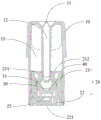
Fig. 2 is a schematic structural diagram of an atomizing assembly according to a first embodiment of the present invention.
The atomization assembly 1 comprises a shell 10, an atomization seat 20 and an atomization core 30; the atomizing base 20 is disposed on the housing 10, and the atomizing core 30 is mounted on the atomizing base 20. The atomizing assembly 1 can be used in particular for atomizing liquids and generating aerosols for different fields, such as medical treatment, electronic cigarettes, etc.; in one embodiment, the atomizing assembly 1 can be used in an electronic cigarette atomizing device for atomizing tobacco tar and generating smoke for a smoker to smoke, as exemplified in the following embodiments; of course, in other embodiments, the atomizing assembly 1 can also be applied to a hair spray apparatus for atomizing hair spray for hair styling; or applied to medical equipment for treating upper and lower respiratory diseases to atomize medical drugs.
One end of the housing 10 forms a mouthpiece section 11. An air outlet channel 12 and a liquid storage bin 13 are further arranged in the shell 10, the liquid storage bin 13 is arranged around the air outlet channel 12, and the air outlet channel 12 is communicated with the suction nozzle portion 11. Wherein, the liquid storage chamber 13 is used for storing liquid, and the liquid storage chamber 13 stores tobacco tar in this embodiment. The liquid storage bin 13 can be made of metal such as aluminum, stainless steel and the like, can also be made of plastic, and only needs to be capable of storing the tobacco tar without reacting with the tobacco tar to cause the tobacco tar to deteriorate; the shape and size of the liquid storage bin 13 are not limited, and the liquid storage bin can be designed according to the requirement.
The atomizing base 20 is located on the side of the reservoir 13 away from the mouthpiece portion 11. Specifically, the housing 10 forms a receiving groove on a side of the liquid storage chamber 13 away from the mouthpiece portion 11, and the atomizing base 20 is disposed in the receiving groove. The atomizing base 20 includes an atomizing top base 21 and an atomizing bottom base 22. The atomizing top base 21 and the atomizing base 22 can be connected through a snap-fit structure. For example, a protrusion may be provided on the atomizing top base 21, and a slot may be provided on the atomizing bottom base 22; or a bulge is arranged on the atomizing base 22, and a clamping groove is arranged on the atomizing top seat 21. The atomizing base 20 can be made of ceramic, stainless steel or other alloys, and only needs to be capable of supporting; the shape and size of the atomizing base 20 are not limited and can be designed as desired.
An atomization cavity 23 is formed between the atomization top seat 21 and the atomization base seat 22, and specifically, an atomization cavity 23 is formed between the atomization surface of the atomization core 30 and the atomization base seat 22. The atomization chamber 23 is communicated with the air outlet channel 12. The two ends of the atomizing core 30 are lapped on the atomizing base 20, and the middle part of the atomizing core 30 is suspended in the atomizing cavity 23. The atomizing core 30 is at least partially accommodated in the atomizing top seat 21, and the atomizing top seat 21 is disposed between the liquid storage bin 13 and the atomizing core 30. The atomizing top seat 21 is provided with a first lower liquid channel 211 and a second lower liquid channel 212; one end of the first lower liquid channel 211 and one end of the second lower liquid channel 212 are communicated with the liquid storage bin 13, and the other end of the first lower liquid channel 211 and the other end of the second lower liquid channel 212 are connected with the atomizing core 30, so that the tobacco tar in the liquid storage bin 13 is guided to the atomizing core 30 through the first lower liquid channel 211 and the second lower liquid channel 212. An air inlet channel 221 is arranged on the atomizing base 22, and the air inlet channel 221 is communicated with the atomizing cavity 23, so that the air inlet channel 221 is communicated with the outside and the atomizing cavity 23. The air inlet channel 221, the atomizing cavity 23 and the air outlet channel 12 form an air flow channel of the atomizing assembly 1.
Wherein, be provided with first sealing member 40 between stock solution storehouse 13 and the atomizing seat 20 to realize atomizing seat 20's sealed, avoid the liquid in the stock solution storehouse 13 to reveal and get into atomizing chamber 23, influence atomizing assembly 1's performance.
The atomizing core 30 includes a heat generating member and a porous member. The liquid in the liquid storage bin 13 enters the porous piece through the first lower liquid channel 211 and the second lower liquid channel 212, and the porous piece is used for storing the liquid and guiding the liquid to the atomizing surface of the heat generating piece through capillary action; the heating element is used for heating and atomizing the liquid on the atomizing surface. The porous member may be a cotton core or a porous ceramic. Because porous piece can water conservancy diversion liquid through the capillary action, through be provided with second sealing member 31 on atomizing core 30, prevent that liquid from getting into atomizing chamber 23 through the capillary action of porous piece, and then influence atomizing subassembly 1 to the atomizing of liquid in the stock solution storehouse 13.
When a user uses the electronic atomization device to suck in the suction nozzle part 11, the outside air enters the atomization cavity 23 through the air inlet channel 221 on the atomization base 22, the atomized smoke carrying the atomization core 30 in the atomization cavity 23 enters the air outlet channel 12, and the smoke reaches the suction nozzle part 11 and is sucked by the user.
Referring to fig. 3 and 4, fig. 3 is a schematic structural view of an atomizing base in a first embodiment of an atomizing assembly provided in the present invention, and fig. 4 is a schematic structural view of a first sealing member in the first embodiment of the atomizing assembly provided in the present invention.
The atomizing top 21 is formed with a depression to form a cavity that communicates the atomizing chamber 23 with the air outlet passage 12. The pocket includes a first sidewall 213, a second sidewall 214, and a bottom wall, the first sidewall 213 being disposed opposite the second sidewall 214. A first through hole 217 is formed on the bottom wall of the pit to communicate the atomizing chamber 23 with the air outlet channel 12; a first lower liquid channel 211 and a second lower liquid channel 212 are formed on the bottom wall of the concave pit, and the first lower liquid channel 211 and the second lower liquid channel 212 are symmetrically arranged and are positioned at two sides of the first through hole 217.
The outer side wall of the atomizing top seat 21 is provided with a groove 50, the first sealing element 40 is sleeved on the atomizing top seat 21, the groove 50 is completely covered by the first sealing element 40, and the first sealing element 40 and the groove 50 are matched to form a ventilation channel. The first end of the groove 50 is communicated with the outside atmosphere, and the second end is communicated with the liquid storage bin 13 through the first lower liquid channel 211 or the second lower liquid channel 212, or directly communicated with the liquid storage bin 13. The first sealing element 40 is matched with the groove 50 to form a ventilation channel, the ventilation channel is separated from the atomizing core 30, the second sealing element 31 on the atomizing core 30 only needs to realize a sealing function, and the requirements on the performance and the size of the second sealing element 31 are reduced; simultaneously, the main body of the ventilation channel is manufactured through the mold in an integrated mode, so that the stability of the section channel is improved, the influence of part tolerance and assembly tolerance is reduced, and the consistency of ventilation smoothness and ventilation function is guaranteed. In another embodiment, a groove 50 may be provided on the surface of the first seal 40 near the atomizing top 21 to form a ventilation channel in cooperation with the outer sidewall of the atomizing top 21.
The first sealing member 40 includes an upper cover 41 and a sidewall 42, and the sidewall 42 completely covers the groove 50 to form the ventilation channel. The upper cover 41 is provided with a second through hole 411, a third through hole 412 and a fourth through hole 413, the second through hole 411 is arranged to expose the first through hole 217, so that the liquid storage bin 13 and the atomizing base 20 are sealed, and the smoothness between the atomizing cavity 23 and the air outlet channel 12 is ensured; the third through hole 412 is provided to expose the first lower liquid channel 211, and the fourth through hole 413 is provided to expose the second lower liquid channel 212, so that the sealing between the reservoir 13 and the atomizing base 20 is achieved, and the liquid in the reservoir 13 can smoothly enter the first lower liquid channel 211 or the second lower liquid channel 212. The upper cover 41 of the first sealing element 40 is attached to the end part of the atomizing top base 21 close to the liquid storage bin 13, and the side wall 42 of the first sealing element 40 is attached to the side wall of the atomizing top base 21; the structural dimension of the first sealing element 40 is matched with that of the atomizing top seat 21, so that the liquid storage bin 13 and the atomizing seat 20 are sealed. A flange 218 is disposed on the entire circumference of the end of the atomizing top base 21 close to the atomizing base 22, and the flange 218 protrudes in a direction away from the side wall of the atomizing top base 21, so that after the first sealing member 40 is sleeved on the atomizing top base 21, one end of the side wall 42 of the sealing member 40 close to the flange 218 abuts against the flange 218. The thickness of the sidewall 42 of the seal 40 is approximately equal to the raised height of the flange 218. After the first sealing member 40 is fitted over the atomizing top base 21 and mounted on the atomizing base 22, the side wall 42 of the first sealing member 40 is substantially flush with the top surface of the flange 218 and the side wall of the atomizing base 22, so that the first sealing member 40 and the atomizing base 20 can be assembled on the housing 10 together.
In this embodiment, the outer side wall of the atomizing top 21 includes a first surface 215 and a second surface 216, the first surface 215 and the second surface 216 are oppositely disposed, and a groove 50 is respectively disposed on the first surface 215 and the second surface 216. The grooves 50 provided on the first surface 215 communicate with the first lower fluid passage 211, and the grooves 50 provided on the second surface 216 communicate with the second lower fluid passage 212.
Referring to fig. 5 and 6, fig. 5 is a schematic top view of an atomizing base according to a first embodiment of an atomizing assembly of the present invention, and fig. 6 is a schematic top view of an atomizing base according to a second embodiment of an atomizing assembly of the present invention.
In another embodiment, one groove 50 is provided on both the first surface 215 and the second surface 216. Referring to fig. 5, both the groove 50 provided on the first surface 215 and the groove 50 provided on the second surface 216 communicate with the first lower liquid passage 211; at this time, the second lower liquid channel 212 may be provided for transferring the tobacco tar, or the second lower liquid channel 212 may not be provided, and the specific design is performed according to the amount of the lower liquid; the liquid storage bin 13 realizes air exchange through the first lower liquid channel 211. Referring to FIG. 6, both groove 50 provided on first surface 215 and groove 50 provided on second surface 216 communicate with second downcomer 212; at this time, the first lower liquid channel 211 may be provided for transferring the tobacco tar, or the first lower liquid channel 211 may not be provided, and the specific design is performed according to the amount of the lower liquid; the liquid storage bin 13 realizes air exchange through the second lower liquid channel 212.
Fig. 7 is a schematic structural diagram of an atomizing base according to another embodiment of the atomizing assembly of the present invention.
In yet another embodiment, two grooves 50 are provided on the first surface 215, wherein one groove 50 communicates with the first lower fluid passage 211 and the other groove 50 communicates with the second lower fluid passage 212; two grooves 50 are provided on the second surface 216, one of the grooves 50 communicating with the first lower fluid passage 211 and the other groove 50 communicating with the second lower fluid passage 212. Through making first lower liquid passageway 211 or second lower liquid passageway 212 and two recesses 50 intercommunication, can increase the scavenging amount, more be favorable to the liquid in the stock solution storehouse 13 to take a breath.
An air vent 60 is arranged at one end of the atomizing top seat 21 close to the atomizing base 22, the air vent 60 is communicated with the outside atmosphere, and the first end of the groove 50 is communicated with the air vent 60, namely, the air exchange channel is communicated with the outside atmosphere. In the present embodiment, the vent holes 60 are through holes, and four vent holes are provided. On first lateral wall 213, the one end that is close to atomizing base 22 is provided with two air vents 60, and two air vents 60 all run through first lateral wall 213, and air vent 60 one end communicates with atomizing chamber 23, and the other end communicates with recess 50. The two vent holes 60 are symmetrically arranged, one of which is arranged in the extending direction of the side wall of the first lower liquid passage 211, and the other of which is arranged in the extending direction of the side wall of the second lower liquid passage 212. Two vent holes 60 are arranged on the second side wall 214 and close to one end of the atomizing base 22, the two vent holes 60 penetrate through the second side wall 214, the two vent holes 60 are symmetrically arranged, one vent hole is arranged in the extending direction of the side wall of the first lower liquid channel 211, and the other vent hole is arranged in the extending direction of the side wall of the second lower liquid channel 212.
Since the vent hole 60 is a through hole, the vent hole 60 communicates with the atomizing chamber 23. In this embodiment, the side wall 42 of the first sealing member 40 covers the vent hole 60, since the vent hole 60 is communicated with the atomizing chamber 23, the atomizing chamber 23 is communicated with the external atmosphere through the air inlet channel 221 arranged on the atomizing base 22, and the external atmosphere enters the ventilation channel through the air inlet channel 221, the atomizing chamber 23 and the vent hole 60. Wherein the vent 60 is spaced from the flange 218 such that the side wall 42 of the seal member 40 completely covers the vent 60. In another embodiment, the side wall 42 of the first sealing member 40 only covers the recess 50 and does not cover the vent hole 60 or only covers a part of the vent hole 60, the vent hole 60 is directly communicated with the external atmosphere through the opening of the side wall of the housing 10, and the external atmosphere enters the ventilation channel through the vent hole 60 and does not need to pass through the atomizing chamber 23; since the vent 60 communicates with the atomizing chamber 23, the external atmosphere can enter the atomizing chamber 23 through the vent 60 in addition to the air inlet passage 221 into the atomizing chamber 23.
Wherein, the section of the vent 60 is square, and the width of the groove 50 is smaller than that of the vent 60. In one embodiment, an opening is provided in a side wall of the vent 60 that allows the vent 60 to communicate with the recess 50. In another embodiment, a recess is formed on the inner surface of the sidewall of the vent 60, and one end of the recess is connected to the groove 50, the recess allowing the vent 60 to communicate with the groove 50.
In another embodiment, the vent 60 is a blind hole. The vent 60 is disposed at an end of the first sidewall 213 or the second sidewall 214 near the atomizing base 22. The recess 50 communicates with the vent 60 through an opening in the side wall of the blind bore, the vent 60 communicating with the atomising chamber 23. The outside atmosphere enters the atomizing cavity 23 through the air inlet channel 221, and then enters the ventilation channel through the atomizing cavity 23 and the vent 60, so that ventilation of the liquid storage bin 13 is realized. The ventilation holes 60 are blind holes, and the ventilation effect can be achieved.
A ventilation hole 70 is formed in a side wall of the first lower fluid passage 211 or the second lower fluid passage 212, and the ventilation hole 70 communicates the first lower fluid passage 211 or the second lower fluid passage 212 with the groove 50, that is, the ventilation hole 70 communicates the first lower fluid passage 211 or the second lower fluid passage 212 with the ventilation passage.
In one embodiment, an opening 71 is formed at an end edge of the side wall of the first lower liquid channel 211 or the second lower liquid channel 212 close to the liquid storage bin 13, the opening 71 extends from an outer surface to an inner surface of the side wall of the first lower liquid channel 211 or the second lower liquid channel 212, i.e., penetrates through the side wall of the first lower liquid channel 211 or the second lower liquid channel 212, the opening 71 communicates the first lower liquid channel 211 or the second lower liquid channel 212 with the groove 50, the upper cover 41 covers the opening 71, and the upper cover 41 of the first sealing member 40 and the opening 71 cooperate to form the ventilation hole 70.
In another embodiment, the ventilation holes 70 are disposed at the middle position of the side wall of the first lower fluid passage 211 or the second lower fluid passage 212, and are not disposed at the end of the side wall of the first lower fluid passage 211 or the second lower fluid passage 212 close to the fluid storage tank 13. A through hole is formed in the bottom wall of one end, close to the liquid storage bin 13, of the groove 50 to form a ventilation hole 70, and the groove 50 is communicated with the first lower liquid channel 211 or the second lower liquid channel 212 through the through hole, so that ventilation of the liquid storage bin 13 is achieved; that is, a through hole is formed at one end of the side wall of the first lower liquid channel 211 or the second lower liquid channel 212 close to the reservoir 13, the through hole penetrates through the side wall of the first lower liquid channel 211 or the second lower liquid channel 212, and the through hole connects the first lower liquid channel 211 or the second lower liquid channel 212 with the groove 50. The ventilation holes 70 are provided in the bottom wall of the recess 50, and the ventilation effect can be also achieved.
The groove 50 is of a one-way flow guiding structure, so that outside air can enter the liquid storage bin 13 through the ventilation channel. After the liquid in the stock solution storehouse 13 gets into the passageway of taking a breath, because the recess is one-way water conservancy diversion structure, there is the choked flow effect to the transmission of liquid in the passageway of taking a breath, can prevent that the liquid in the stock solution storehouse 13 from getting into atomizing chamber 23 through passageway of taking a breath, air vent 60, and the choked flow effect can be more showing when reliability tests such as suction or negative pressure especially, and then improves the weeping phenomenon.
In the present embodiment, the groove 50 is a continuous curved channel to form a Tesla valve; the direction of extension of the tesla valve passageway extends from an end proximal to the reservoir 13 to an end distal to the reservoir 13 on either the first surface 215 or the second surface 216 of the atomizing top mount 21. According to the characteristics of the Tesla valve, the valve is smooth in the forward direction and choked in the reverse direction. The Tesla valve formed by the groove 50 enables the external atmosphere to pass through the Tesla valve in the forward direction during air exchange, and the external atmosphere can pass through the air exchange channel almost without resistance so as to enter the liquid storage bin 13; the liquid in the liquid storage bin 13 reversely passes through the Tesla valve, and due to the flow blocking effect of the Tesla valve, the liquid in the use process of the electronic atomization device can be prevented from entering the atomization cavity 23.
In other embodiments, the groove 50 may have other structures, so that only the forward ventilation is required to be smooth, and the reverse flow is required to be blocked, i.e., the one-way flow guiding is required. The groove 50 may also be provided with a check valve, which allows outside air to smoothly enter the liquid storage bin 13, so as to block the flow of the liquid in the liquid storage bin 13 into the atomizing chamber 23. Also can set up on recess 50 and separate the liquid ventilated membrane, external atmosphere can be through separating the liquid ventilated membrane for external atmosphere can realize the circulation in filtration membrane's both sides, and the liquid in the stock solution storehouse 13 can't pass through separating the liquid ventilated membrane, and then prevents that liquid from getting into atomizing chamber 23.
Atomization component in this application includes atomizing seat and sealing member, and atomizing seat includes atomizing footstock and atomizing base, and the sealing member cover is established on the atomizing footstock. Through set up the recess on atomizing footstock's lateral wall, form the passageway of taking a breath with the sealing member cooperation. Because the sealing member cover is established on atomizing footstock, and the recess sets up on atomizing footstock's lateral wall, consequently, the sealing member covers the recess, and the ventilation channel cross-section stability that recess and sealing member cooperation formed is high, receives part tolerance, assembly tolerance influence less, has improved ventilation channel's smoothness. The sealing element only needs to realize the sealing of the atomizing seat, so that the formation of the ventilation channel is indirectly ensured, and the requirements on the performance and the size of the sealing element are reduced.
The above description is only a partial embodiment of the present invention, and not intended to limit the scope of the present invention, and all equivalent devices or equivalent processes performed by the present invention through the contents of the specification and the drawings, or directly or indirectly applied to other related technical fields, are included in the scope of the present invention.