Detailed Description
The application provides a data transmission method, a switch and a site, which are used for solving the problem that the configuration of CPE increases the deployment difficulty of edge sites. The method and the device are based on the same inventive concept, and because the principles of solving the problems of the method and the device are similar, the implementation of the device and the method can be mutually referred, and repeated parts are not repeated.
The following description is made of the title terms related to the embodiments of the present application:
1) a site, in the embodiments of the present application, represents a collection of devices. Devices in the site provide services based on data generated by the data source. The data source may be a device within the site or a device outside the site. In general, sites that are farther from the data source are referred to as center sites, and sites that are closer to the data source are referred to as edge sites. Data centers typically include multiple sites.
2) Services, including but not limited to computing services, storage services, network services, etc., any device or function that a user may access may be considered a service provided by the data center. The service may be provided based on a device in one site, or may be provided based on devices in multiple sites, which is not limited in this embodiment of the present application. Generally, a service deployed in a central site is referred to as a central service or a central cloud service, and a service deployed in an edge site is referred to as an edge service or an edge cloud service.
3) In the embodiment of the present application, devices between different sites communicate with each other via a Wide Area Network (WAN), which is also called an extranet or a public network.
4) The link, or dedicated line, in the embodiments of the present application, means a physical link that carries the WAN between the stations. The long link in the embodiment of the present application includes, but is not limited to, the Internet (Internet), a multi-protocol label switching virtual private network (MPLS VPN), a fifth Generation mobile communication technology (5th-Generation,5G) network, a fourth Generation mobile communication technology (4th-Generation,4G) network, and the like.
5) Payload (payload), where the data packet includes a packet header and a payload, and the payload is used to carry valid data in the data packet, such as service data; the header is used to carry some auxiliary information describing valid data, such as the data amount of the valid data, check bits, and the like. In the embodiment of the present application, the service type of the data packet is a service type of data carried by a payload in the data packet, the two expressions are equivalent, and the embodiment of the present application does not distinguish the two expressions. In addition, the service identifier carried in the data packet may indicate the service type of the data packet.
6) Routing information, in this embodiment of the present application, the routing information may be an address (for example, address 1) used for encapsulating a data packet, where a device indicated by the address 1 is a device on a link corresponding to a service type; other information indicating the link, such as link identification, etc., is also possible.
7) In the description of the present application, the terms "first," second, "and the like, are used for descriptive purposes only and are not to be construed as indicating or implying relative importance, nor order, and two or more of the embodiments of the present invention are intended to be implied as" a plurality "or" the like.
8) "and/or" describes the association relationship of the associated objects, meaning that there may be three relationships, e.g., a and/or B, which may mean: a exists alone, A and B exist simultaneously, and B exists alone.
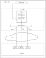
Taking the data center 100 in fig. 1 as an example, an architecture of a data center in the embodiment of the present application is described. In fig. 1, a site 1001 and a site 1002 are exemplarily depicted, the site 1001 and the site 1002 may be two central sites or two edge sites, and the site 1001 and the site 1002 may also be one edge site and one central site, respectively.
Site 1001 includes at least one host running a virtual switch. Illustratively, two hosts, host 110 and host 120, in site 1001 are depicted in FIG. 1. The host runs a virtual machine and a virtual switch, for example, the host 110 is deployed with a virtual machine 111 and a virtual switch 112, and the host 120 is deployed with a virtual machine 121 and a virtual switch 122; in the embodiment of the present application, the number of virtual machines running on a host is not limited, and fig. 1 only takes the case where each host deploys one virtual machine as an example, and in a specific application, the number of virtual machines deployed on a host may be set as needed. In addition to the host running the virtual switch, the site 1001 may also include a host not running the virtual machine and the virtual switch, for example, the host not deploying the virtual machine and the virtual switch may be used as a management host, manage other hosts in the site 1001, or provide a service with a higher requirement on security or computational performance.
Optionally, as shown in fig. 1, site 1001 may also deploy physical switch 160 and CPE 170. For example, only one physical switch and one CPE are drawn in fig. 1, in this embodiment of the application, one or more physical switches may be deployed in a site, and one or more CPEs may also be deployed in the site. Physical switch 160 is connected to each host of site 1001 and forwards data packets between each host and between the host and the CPE. The CPE170 is connected to the physical switch 160 and the WAN, respectively, receives data packets from the physical switch 160, and forwards the received packets to the site 1002 via the WAN.
Similar to the architecture of site 1001, site 1002 includes at least one host running a virtual switch, the host also running a deployment virtual machine. In fig. 1, a site 1002 includes three hosts, namely a host 130, a host 140, and a host 150, where the host 130 is deployed with a virtual machine 131 and a virtual switch 132, the host 140 is deployed with a virtual machine 141 and a virtual switch 142, and the host 150 is deployed with a virtual machine 151 and a virtual switch 152; although not shown in fig. 1, the site 1002 may also include a host that does not deploy a virtual machine, and the functions of the host that does not deploy a virtual machine can be referred to in the foregoing, and are not described herein again. Optionally, site 1002 may also include physical switch 180 and CPE 190.
The equipment in station 1001 and station 1002 interwork with the WAN between CPE170 and CPE 190. The links carrying the WAN may be one or more, and station 1001 and station 1002 may communicate with each other via one or more different links. When the types of the services of the data carried in the payload of the data packet are different, the links applicable to forwarding the data packet in the WAN may be different. Taking communication, video and mail services as examples, the communication service requires clear call quality, short transmission time and short data interval, so that the data message of the communication service is generally applicable to a link with smaller transmission delay; the data volume of the transmission of the video service is large, so that the data message of the video service is suitable for a link with higher bandwidth; compared with communication service, the requirement of mail service on transmission delay is low, and the internet can meet the service requirement only by ensuring that the mail service is successfully transmitted within a certain time range. Data packets of one or more traffic types may be transmitted between station 1001 and station 1002, with each data packet corresponding to one or more links between station 1001 and station 1002.
Hereinafter, based on the site 1001 and the site 1002 shown in fig. 1, a data transmission method will be described by taking a process in which the virtual machine 111 in the site 1001 sends a data packet 1 to the virtual machine 131 in the site 1002 as an example.
In the transmission process of the data packet 1, the virtual machine 111 sends the data packet 1 to the virtual switch 113 on the host 110, where the destination device of the data packet 1 is the virtual machine 131 on the site 1002, and the data packet 1 carries the destination address as the address of the virtual machine 131. The virtual switch 111 identifies that the destination device of the data message 1 is located at the site 1002 according to the destination address carried by the data message 1; virtual switch 111 forwards the datagram 1 to physical switch 160. After receiving the data packet 1, the physical switch 160 sends the data packet 1 to the CPE170, and the CPE170 is used as the last device through which the data packet 1 passes before leaving the site 1001, and needs to select a link for the data packet 1 according to the service type of data carried in the payload of the data packet 1. Specifically, a plurality of ports on CPE170 are each connected to a different link, with link 1 and link 2 being exemplarily depicted in fig. 1. The CPE170 identifies a destination address of the data packet 1, determines a forwarding port in the multiple ports according to a service identifier to which data carried in a payload of the data packet 1 belongs, forwards the data packet 1 to a link connected to the port through the determined port, and further forwards the data packet to the CPE190 in the site 1002 through the link.
After receiving the data packet 1, the CPE190 in the site 1002 transmits the data packet 1 to the physical switch 180 according to the address of the virtual machine 131 carried in the data packet 1, and after receiving the data packet 1, the physical switch 180 transmits the data packet 1 to the virtual switch 132 on the host 130 according to the address of the virtual machine 131, and the virtual switch 132 forwards the data packet 1 to the virtual machine 131.
As can be seen from the above data transmission process, data transmission between two stations requires the participation of the CPE to complete the link selection. When the space of the edge site is limited, the CPE configuration may increase the difficulty of edge site deployment.
Based on this, in the embodiment of the present application, another data center architecture is provided, as shown in fig. 2, taking the data center 100 as an example, the data center 100 includes a site 1001 and a site 1003, and fig. 2 only shows a connection manner between the virtual switch 111 and the switch 200 in the site 1001, it should be understood that the site 1001 may also include other virtual machines, and reference may be made to the description of the connection manner between the virtual machine 111 and the switch 200 in fig. 2 for the connection manner between the other virtual machines and the switch 200, which is not described herein again.
The virtual machine 111 is connected to a switch 200, and the switch 200 is connected to a plurality of links in the WAN. The switch 200 has one or more ports, each port connected to a link carrying a WAN. As exemplarily depicted in fig. 2, a station 1003 is connected between the station 1001 and the station 1003, and a link 1, a link 2, and a link 3 carrying a WAN are connected therebetween; link 1, link 2, and link 3 are connected to device 1, device 2, and device 3, respectively, in the site 1003. The device types of the device 1, the device 2, and the device 3 are related to the specific architecture of the station 1003, and the embodiment of the present application is not limited thereto. Alternative embodiments of the specific architecture of the station 1003 are described below, along with device 1, device 2, and device 3.
The switch 200 acquires the data packets (data packet 2, data packet 3, data packet 4, and data packet 5 in this embodiment) sent by the virtual machine 110, and sends the data packets to the station 1003 through a link corresponding to the service type of the data packet in a plurality of links connected to the station 1003.
Optionally, the station 1001 further includes a controller 300, and the controller 300 is connected to the switch 200 to control the switch 200 in the station 1001.
In this embodiment, the switch 200 identifies the service type of the data packet (e.g., data packet 1, data packet 2, data packet 3, and data packet 4 in this embodiment) of the virtual machine 110, determines routing information corresponding to the service type, then sends the data packet according to the routing information, and transmits the data packet to the station 1003 through a link corresponding to the service type in links between the station 1001 and the station 1003; the switch 200 also encapsulates the data packet according to routing information before transmitting the data packet.
The switch 200 may also obtain routing information from the controller 300 by sending a query request carrying the service type (and also carrying the destination address of the data packet).
Optionally, the switch 200 may encrypt the data packet based on an encryption policy determined by a service type of the data packet; for the same data packet of the same service type, source address and destination address, the switch 200 may determine the difference data between the subsequent data packet and the first data packet, and send the difference data in the same manner as sending the first data packet.
The type of the switch 200 is not limited in the embodiment of the present application. Switch 200 may be a virtual switch in site 1001, or may be a physical switch in site 1001, and switch 200 may further include a virtual switch and a physical switch. Two specific site 1001 architectures are depicted in fig. 3 and 4. In the station 1001 shown in fig. 3, the station 1001 includes the virtual switch 112 and the physical switch 160, in this case, the switch 200 may be implemented by the virtual switch 112, or by the physical switch 160, and in addition, the switch 200 may be implemented by both the virtual switch 112 and the physical switch 160. In site 1001 as shown in fig. 4, switch 200 may be implemented by virtual switch 112.
The following describes the architecture of the station 1001 in fig. 3 and 4, respectively.
As shown in fig. 3, the present application provides another data center architecture. Still taking the data center 100 as an example, the data center 100 includes a station 1001 and a station 1003, and for example, fig. 3 only shows a connection manner between the host 110 and the physical switch 160 in the station 1001, it should be understood that the station 1001 may further include other hosts, and reference may be made to the foregoing description of the connection manner between the host 110 and the physical switch in fig. 1 for the connection manner between the other hosts and the physical switch, which is not described herein again. There are one or more ports on physical switch 180, each port connected to a link carrying a WAN. As exemplarily depicted in fig. 3, a station 1003 is connected between the station 1001 and the station 1003, and a link 1, a link 2, and a link 3 carrying a WAN are connected therebetween; link 1, link 2, and link 3 are connected to device 1, device 2, and device 3, respectively, in station 1003. The device types of the device 1, the device 2, and the device 3 are related to the specific architecture of the station 1003, and the embodiment of the present application is not limited thereto. The specific architecture of the station 1003 and device 1, device 2, and device 3 are described below.
Optionally, the controller 300 is connected to the virtual switches in the site 1001, so as to implement unified control on the virtual switches in the site 1001.
The controller 300 may be deployed in the site 1001 or outside the site 1001, and the controller 300 may control only the virtual switch in the site 1001, or may implement unified control of virtual switches of a plurality of sites.
As shown in fig. 4, which is another schematic architecture diagram of the data center provided in the embodiment of the present application, still taking the data center 100 as an example, the data center 100 includes a site 1001 and a site 1003, and exemplarily, only the hosts 110 and 120 in the site 1001 are drawn in fig. 4. Each host in the at least two hosts is directly interconnected without passing through a physical switch, so as to establish connection between the virtual switches on the hosts.
As shown in fig. 4, each virtual switch on host 110 and host 120 has one or more ports thereon. Specifically, virtual switch 112 has port 112a, and virtual switch 122 has port 122a, port 122b, port 122c, and port 122 d. The port 112a of the virtual switch 112 is connected to the port 122a of the virtual switch 122, so as to connect the host 110 and the host 120, and realize data intercommunication between the host 110 and the host 120. Further, ports 122b, 122c and port 122d on virtual switch 122 are connected to link 1, link 2 and link 3, respectively, in the WAN. When the virtual machine 111 on the host 110 needs to access the site 1003, the virtual machine 111 sends the data packet to the virtual switch 122 on the host 120 through the port 112a and the port 122a, and then the virtual switch 122 forwards the data packet to the WAN through the corresponding link. As exemplarily depicted in fig. 4, a station 1003 is connected between the station 1001 and the station 1003, and a link 1, a link 2, and a link 3 carrying a WAN are connected; link 1, link 2, and link 3 are connected to device 1, device 2, and device 3, respectively, in station 1003. The device types of the device 1, the device 2, and the device 3 are related to the specific architecture of the station 1003, and the embodiment of the present application is not limited thereto. The specific architecture of the station 1003 and device 1, device 2 and device 3 are described below.
Alternatively, the controller 300 connects the virtual switch 112 in the host 110 and the virtual switch 122 in the host 120 of the station 1001, and the controller 300 can implement unified control over the virtual switch 112 and the virtual switch 132 by forwarding the flow table. The controller 300 may also issue routing information at the request of the virtual switch 112 to control the virtual switch 112.
The controller 300 may control only the virtual switch in the site 1001, or may realize unified control of the virtual switches of a plurality of sites.
The architecture of station 1003 in fig. 2, 3, or 4 may refer to station 1001 in fig. 1, 2, 3, or 4. When the station 1003 adopts a structure similar to the station 1001 shown in fig. 1, the station 1003 includes at least one host, a physical switch, and a plurality of CPEs, and all of the device 1, the device 2, and the device 3 are CPEs; the connection relationship between the physical switch and each CPE and between at least one host and the physical switch can be referred to as the connection relationship between the host and the physical switch in fig. 1. When the station 1003 adopts a structure similar to the station 1001 shown in fig. 2, the station 1003 includes at least one switch, and any one of the switches of the station 1003 may be used for the device 1, the device 2, and the device 3.
When the station 1003 adopts a structure similar to the station 1001 shown in fig. 3, the station 1003 includes at least one host running a virtual switch and a physical switch, the device 1, the device 2, and the device 3 may be virtual switches on any host of the station 1003, and the device 1, the device 2, and the device 3 may also be any physical switch of the station 1003.
When the station 1003 adopts a structure similar to the station 1001 shown in fig. 4, the station 1003 includes at least one host running a virtual switch, and the device 1, the device 2, and the device 3 may be virtual switches on any host of the station 1003.
It should be noted that fig. 2, fig. 3, and fig. 4 are only exemplary diagrams illustrating device 1, device 2, and device 3 existing in station 1003, and when there are multiple links carrying WANs between station 1001 and station 1003, a device connected to each link is deployed in station 1003.
Based on the data centers in fig. 2 to fig. 4, the embodiment of the present application provides another data transmission method. The switch receives the data message, identifies the service type of the data message, determines routing information (such as address 1, link identification and other information in the following) according to the service type, forwards the data message according to the routing information, and transmits the data message through a link corresponding to the service type. Therefore, the selection of the link can be realized without deploying CPE in the station, the deployment difficulty of the station is reduced, the space of a station machine room is saved, the saved space can be used for deploying more hosts or other equipment, and the service capability of the station is convenient to improve.
It should be noted that the routing information determined according to the service type may indicate a bearer link for transmitting the data packet. The bearer link of the data packet refers to a link that carries the data packet when the data packet is transmitted between two stations, and the embodiment of the present application does not limit the way in which the routing information indicates the bearer link that transmits the data packet, for example, the routing information may be an address (such as address 1 in the following) used for encapsulating the packet, and the device indicated by the address is a device on the bearer link; the routing information may also carry identification information of the link, such as a link identification (e.g., identification of link 1, hereinafter), a link number, and the like.
Specifically, another data transmission provided in the embodiment of the present application is described by taking an example in which the virtual switch 112 in the host 110 transmits the data packet 2 from the virtual machine 111. The service type 1 of the data carried in the payload of the data packet 2 corresponds to the link 1 in fig. 3 and 4, and the data packet 2 can be forwarded to the destination device through the link 1 by the following method. As shown in fig. 5, the method includes:
step 501: virtual machine 110 sends datagram 2 to virtual switch 112.
The traffic type 1 of data carried in the payload of data message 2 includes, but is not limited to, mail, video, communications, games, office, financial, stock, etc.
Data message 2 also carries a source address and a destination address. The source address is the address of the virtual machine 111 and the destination address is the address of the destination device of the data message 2. The source address and the destination address include, but are not limited to, an Internet Protocol (IP) address, a Media Access Control (MAC) address, a port number, and the like.
Step 502: the virtual switch 112 determines the service type of the data packet 2, that is, the service type 1, determines the address of the encapsulated data packet 2 according to the service type 1, and encapsulates the data packet 2 according to the determined address, the packet header of the encapsulated data packet 2 carries the address of the device 1 in the site 1003, that is, the address 1, and the device 1 is connected to the site 1001 through the link 1.
The virtual switch 112 stores a correspondence between the service type 1 and the address 1, and optionally, the correspondence may be recorded in a forwarding flow table. The forwarding flow table also records a correspondence between each service identifier (the service identifier may indicate a service type) and an address, where the address corresponding to each service identifier is an address of a device connected to the station 1001 through a corresponding link in the station 1003. Alternatively, the forwarding flow table of the virtual switch 112 may be generated by the controller 300 and issued to the virtual switch 112.
Optionally, before determining the address 1 according to the service identifier, the virtual switch 112 further determines, according to the destination address of the data packet 2, that the data packet 2 needs to be transmitted across sites, that is, it is determined that the virtual machine 111 and the destination device of the data packet 2 are located at different sites. In the embodiment shown in fig. 3, if the destination device indicated by the destination address is located at the site 1003, and if the destination address is the address of the virtual machine 131, the datagram 2 needs to be transmitted across sites, and the virtual switch 112 encapsulates the datagram 2.
Alternatively, the address 1 may be determined according to the destination address of the data packet 2 and the service type of the data carried in the payload of the data packet. The forwarding flow table may also record the destination address of each data packet, and the corresponding relationship between the service type and the address of the data carried in the payload of the data packet. That is to say, when the service types of the data carried by the payloads of the two data packets are the same, but the destination addresses of the two data packets are different, the links corresponding to the two data packets may be different, and therefore, when determining the address of the encapsulated data packet 2, optionally, the address of the encapsulated data packet 2 is determined according to the destination address and the service type of the data packet 2. The virtual switch 112 may determine address 1 from the destination address of the data packet 2 and the traffic type 1 by querying the forwarding flow table.
If the virtual switch 112 does not record the correspondence between the service type 1 and the address 1, the virtual switch 112 sends an inquiry request 1 to the controller 300, where the inquiry request 1 is used to inquire the controller 300 about the address 1 corresponding to the service type 1, and the inquiry request 1 may carry the service type 1 of the data packet 2. For example, the query request 1 may carry a service identifier 1, and the service identifier 1 may indicate a service type 1.
Similarly, if the address 1 is determined according to the destination address of the data message 2 and the service type 1 of the data carried in the payload of the data message 2; under the condition that the forwarding flow table of the virtual switch 112 does not record the corresponding relationship between the service type 1 and the destination address of the data packet 2 and the address 1, the virtual switch 112 may also send an inquiry request 2 to the controller 300, where the inquiry request 2 is used to inquire the controller 300 about the address 1 corresponding to both the service type 1 and the destination address of the data packet 2; the query request 2 may carry the service type 1 of the data packet 2 and the destination address of the data packet 2.
After receiving the query request 1 or the query request 2, the controller 300 may determine the address 1 according to the service type 1 of the data carried in the payload of the data packet 2; as a possible implementation manner, the controller may determine the address 1 according to the service type 1 of the data carried in the payload of the data packet 2 and the destination address of the data packet 2; address 1 is then carried in the query response and fed back to virtual switch 112.
Step 503: the virtual switch 112 forwards the encapsulated data packet 2 to the corresponding link, i.e. link 1, according to the address 1.
As shown in the site 1001 of fig. 3, the virtual switch 112 may forward the encapsulated datagram 2 to the physical switch 160 according to the address 1.
After receiving the encapsulated datagram 2, the physical switch 160 may determine a port on the physical switch 160 according to the address 1, and forward the encapsulated datagram 2 through the determined port, where the determined port is connected to the link 1.
As a possible implementation, the physical switch 160 stores a forwarding table, which records the correspondence between the address and the port of the physical switch, and the physical switch 160 may determine the port of the physical switch 160 corresponding to the address 1 by querying the forwarding table.
As shown in the site 1001 of fig. 4, the virtual switch 112 forwards the encapsulated data packet 2 to the virtual switch 122 according to the address 1. Illustratively, virtual switch 112 sends encapsulated datagram 2 via port 112a to encapsulated datagram 2. For example, the forwarding flow table in the virtual switch 112 may further record the relationship between the address and the port of the virtual switch 112, and the virtual switch may query the forwarding flow table to determine the port 112a according to the address 1.
After receiving the encapsulated data packet 2, the virtual switch 122 may query a forwarding flow table in the virtual switch 122, and determine a port on the virtual switch 122 according to the address 1; the forwarding flow table records the correspondence between the address and the port of the virtual switch 122, and the forwarding flow table may be determined by the controller 300 according to the relationship between the port of the virtual switch 122 and the link.
After determining the port 122c, the virtual switch 122 may forward the encapsulated datagram 2 through the determined port 122 c.
It should be noted that, the embodiment of the present application does not limit the specific path of the data message 2 for implementing forwarding in the link 1.
Step 504: after receiving the encapsulated data packet 2 from the corresponding link, the device 1 decapsulates the encapsulated data packet 2 to obtain the data packet 2.
Step 505: the device 1 forwards the data packet 2 according to the destination address of the data packet 2, and forwards the data packet 2 to the destination device.
Illustratively, if the station 1003 employs the structure shown in fig. 1, the device 1 is a CPE190, the CPE190 decapsulates, and after decapsulation, sends the datagram 2 to the physical switch of the station 1003. The physical switch of the site 1003 sends the datagram 2 to the virtual switch in the site 1003 according to the destination address of the datagram 2, and the virtual switch in the site 1003 sends the datagram 2 to the destination device.
Illustratively, if the station 1003 employs the structure shown in fig. 3, the device 1 is a virtual switch in the station 1003. The encapsulated data packet 2 reaches the virtual switch of the site 1003 through the physical switch in the site 1003, the virtual switch of the site 1003 executes decapsulation after receiving the encapsulated data packet 2, and sends the data packet 2 to a destination device according to a destination address of the data packet 2 after decapsulation.
For example, if the station 1003 has the structure shown in fig. 3, the device 1 may also be a physical switch in the station 1003. The link 1 of the encapsulated data packet 2 reaches the physical switch of the site 1003, the physical switch of the site 1003 executes decapsulation after receiving the encapsulated data packet 2, sends the data packet 2 to the virtual switch of the site 1003 according to the destination address of the data packet 2 after the decapsulation, and then sends the data packet 2 to the destination device by the virtual switch of the site 1003 according to the destination address of the data packet 2.
For example, if the station 1003 has the structure shown in fig. 4, the device 1 is a virtual switch in the station 1003, and the virtual switch in the station 1003 decapsulates the received encapsulated data packet 2 after receiving the encapsulated data packet 2, and sends the data packet 2 to the destination device according to the destination address of the data packet 2 after decapsulation.
In the above description, the virtual switch 112 determines the address 1 according to the service type of the data carried by the payload of the datagram 2, and encapsulates the datagram 2 according to the address 1, it should be understood that, in some possible embodiments, when a physical switch is deployed in the site 1001, for example, in the site 1001 shown in fig. 2, the virtual switch 112 may also not perform the above operation, and the physical switch 160 in the site 1003 performs the above operation, specifically, taking the physical switch 160 in the host 110 as an example to transmit the datagram 3 from the virtual machine 111, another data transmission provided in the embodiment of the present application is described based on the data center shown in fig. 3. The service type 1 of the data carried in the payload of the data packet 3, and the destination device indicated by the destination address of the data packet 3 are located at the station 1003, and corresponding to the link 1 in fig. 3, the data packet 2 may be forwarded to the destination device through the link 1 by the following method. As shown in fig. 6, the method includes:
step 601: virtual machine 110 sends data packet 3 to virtual switch 112.
Step 602: after receiving the data packet 3, the virtual switch 112 determines that the data packet 2 needs to be transmitted across sites according to the destination address of the data packet 3, and sends the data packet 3 to the physical switch 160.
Step 603: the physical switch 160 determines the service type 1 of the data carried by the payload of the data packet 3, and determines the address of the encapsulated data packet 3 according to the service type 1, that is, the address 1, and the device 1 indicated by the address 1 is connected to the station 1001 via the link 1.
The physical switch 160 includes a pre-configured forwarding table, in which a corresponding relationship between the service type 1 and the address 1 is recorded. The forwarding table may record a corresponding relationship between each service identifier (the service identifier may indicate a service type) and an address, and the physical switch 160 may query the forwarding table configured in the physical switch 160, and determine address 1 according to the service type 1. The forwarding table in the physical switch 160 may be manually preconfigured or may be sent to the physical switch 160 in advance by the controller 300.
Optionally, the physical switch 160 may determine the address 1 according to the service type 1 of the data carried by the payload of the data packet 3 and the destination address of the data packet 3.
The forwarding table in the physical switch 160 may further record a destination address of each data packet, and a corresponding relationship between a service type of data carried in a payload of the data packet and an address, and the physical switch 160 may determine the address 1 according to the destination address of the data packet 3 and the service type 1 by querying the forwarding table.
If the forwarding table in the physical switch 160 does not record the corresponding relationship between the service type 1 and the address 1, or does not record the corresponding relationship between the service type 1 and the destination address of the data packet 3 and the address 1, the physical switch 160 may also obtain the address 1 from the controller 300 by sending an inquiry request to the controller 300. The manner in which the physical switch 160 sends the query request to acquire the address 1 from the controller 300 may refer to the manner in which the virtual switch 112 sends the query request 1 or the query request 2 acquires the address 1 from the controller 300 in the embodiment shown in fig. 5, and is not described herein again.
Step 604: the physical switch 160 encapsulates the data packet 3 according to the address 1, and the packet header of the encapsulated data packet 3 carries the address 1.
Step 605: the physical switch 160 determines a port on the physical switch 160 according to the address 1, and forwards the encapsulated data packet 3 through the determined port, where the determined port is connected to the link 1.
The manner in which the physical switch 160 determines the port on the physical switch 160 according to the address 1 may refer to the related description of step 503 in the embodiment shown in fig. 5, and is not described herein again.
Step 606: after receiving the encapsulated data packet 3 from the corresponding link, the device 1 decapsulates the encapsulated data packet 3 to obtain the data packet 3. The operation performed by the device 1 in step 606 is the same as the operation performed by the device 1 in step 504, which can be referred to the foregoing, and is not described herein again.
Step 607: the device 1 forwards the data packet 3 according to the destination address of the data packet 3, and forwards the data packet 3 to the destination device indicated by the destination address of the data packet 3. The operation performed by the device 1 in step 607 is the same as the operation performed by the device 1 in step 505, and reference may be made to the foregoing description, which is not described herein again.
In the embodiment shown in fig. 5 and fig. 6, after receiving a data packet (e.g., data packet 2 or data packet 3) of the virtual machine 111, the virtual switch 112 or the physical switch 160 may determine an address 1 and transmit the data packet; in a possible implementation manner, the virtual switch 112 may also determine routing information (such as a link identifier or an address) corresponding to the service type of the data packet, and notify the physical switch 160 of the routing information, and the physical switch sends the data packet according to the routing information, that is, the virtual switch 112 and the physical switch 160 may cooperate to implement transmission of the data packet.
The embodiment of the application also provides another data transmission method. Based on the data center in fig. 3, the following description takes an example that the virtual switch 112 in the host 110 and the physical switch 160 cooperate to transmit the data packet 4 from the virtual machine 111. The service type 1 of the data carried in the payload of the data packet 4 corresponds to the link 1 in fig. 3, and the data packet 4 can be forwarded to the destination device through the link 1 by the following method. As shown in fig. 6, the method includes:
step 701: virtual machine 110 sends data packet 4 to virtual switch 112.
Step 702: the virtual switch 112 determines the service type 1 of the data carried by the payload of the data packet 4, and determines the address 1 of the encapsulated data packet 4 according to the service type 1.
The manner in which the virtual switch 112 determines the address 1 can be referred to the related description of step 502, and is not described herein again.
Step 703: virtual switch 112 sends address 1 and datagram 4 to physical switch 160.
Step 704: the physical switch 160 encapsulates the data packet 4 according to the address 1, and a packet header of the encapsulated data packet 4 carries the address 1.
In step 702, the routing information determined by the virtual switch 112 according to the service type 1 is taken as the address 1 of the encapsulated data packet 4 for example, in fact, the routing information determined by the virtual switch 112 according to the service type 1 may also be used to indicate information of the link 1, such as the identifier of the link 1. In step 704, physical switch 160 may determine address 1 of encapsulated datagram 4 based on the identification with link 1, and encapsulate datagram 4 based on address 1.
The correspondence between the identifier of link 1 and address 1 may be recorded in a forwarding table in physical switch 160, and the physical switch may determine address 1 by querying the forwarding table through the identifier of link 1.
Step 705: physical switch 160 may determine the port on physical switch 160 from address 1. The manner of determining the port by the physical switch 160 may refer to the relevant description of step 503, and is not described herein again.
Optionally, physical switch 160 may also determine the port on physical switch 160 based on the identification of link 1.
Step 706: the physical switch 160 forwards the encapsulated datagram 4 through the determined port.
Step 707: in step 504, reference may be made to the related description of step 504, which is not repeated herein.
Step 708: in step 505, reference may be made to the related description of step 505, which is not repeated herein.
As can be seen in the embodiments shown in fig. 5-7, the links between station 1001 and station 1003 may each correspond to one or more different traffic types. The corresponding relationship between each link and the service type is embodied in routing information (such as an address, a link identifier, and the like) determined according to the service type, for example, the routing information may be an address of a device on the link corresponding to the service type, or may be information indicating the link, such as an identifier of the link.
The data messages of some service types have higher security requirements, the transmission security of data needs to be ensured in the transmission process, the data messages are not easy to be intercepted by an attacker, and the data messages of the service types can be encrypted. For example, for a service with a high security requirement, such as a financial service, an encryption algorithm with a higher encryption level is used for a data packet of the service type, such as a Secure Socket Layer (SSL), an internet protocol security (IPsec), and the like; for services without special requirements on security, such as video services, the data message of the service type may not be encrypted. In addition, the encryption policy may also be an encryption policy for data packets carrying different destination addresses.
As a possible implementation manner, before encapsulating the data packet 2, the virtual switch 112 may further determine an encryption policy 1 according to the service type 1 and/or the destination address of the data packet 2, and encrypt the data packet 2 based on the encryption policy 1.
Optionally, the forwarding flow table in the virtual switch 112 may not only represent the above correspondence, but also include an encryption policy (e.g., encryption policy 1 in this embodiment), where the encryption policy indicates whether encryption is required and a corresponding encryption algorithm.
Correspondingly, after the virtual switch in the site 1003 receives the encrypted data packet 2, the virtual switch may also query a forwarding flow table, and determine a decryption policy 1 according to the service type and/or the destination address; since the encryption policy and the decryption policy are relative, the virtual switch in the station 1003 can decrypt the encrypted datagram 2 based on the decryption policy 1.
Optionally, after sending the data packet 2 to the virtual switch 112, the virtual machine 110 may also send a data packet 3 with the same service type and carrying the same destination address and source address. After receiving the data packet 3, the virtual switch 112 queries a forwarding flow table, and if it is determined that data deduplication needs to be performed on the data packet of the service type, data deduplication needs to be performed on the data packet 3.
It should be noted that, in some scenarios, in a certain time period, one virtual machine may send multiple data messages to the same virtual machine; the data messages have the same service type and carry the same destination address and source address; the data carried in the data messages are small in difference; in this case, in order to speed up the data transmission process, data deduplication may be performed on subsequent data packets after the first complete data packet is sent; for example, the same data in the subsequent data packet as the first data packet may be removed, and only the differential packet carrying the differential data is sent, in this embodiment, a process of removing the same data in the subsequent data packet as the first data packet is referred to as data deduplication.
Specifically, the virtual switch 112 compares the data packet 2 with the data packet 5, determines the difference data between the payload data of the data packet 2 and the payload data of the data packet 5, and generates a difference packet carrying the difference data; the service type of the differential message is the same as that of the data message 2, and carries the same destination address and source address.
In order to distinguish the complete data packet from the difference packet generated after the data deduplication, the difference packet may carry identification information of the difference packet, which is used to indicate that the packet is the difference packet after the data deduplication, and the carried payload data is the difference data.
The difference message can also indicate the difference position of the data message 5 and the data message 2; to clarify the position of the difference data carried by the difference message in the data message 2. For example, the size of the data carried by the data message 5 and the data message 2 is 100 bytes, where the size is different from the 20 th byte to the 30 th byte, the difference message may indicate that the difference position between the data message 5 and the data message 2 is located from the 20 th byte to the 30 th byte, and may also indicate that the difference starting position between the data message 5 and the data message 2 is located at the 20 th byte. The embodiment of the present application does not limit the way in which the difference packet indicates the difference position between the data packet 5 and the data packet 2, and the above-mentioned way is an example.
The embodiment of the present application does not limit the number of the data packets 5, the virtual machine may send a plurality of data packets 5 to the virtual switch 112, and the virtual switch 112 may generate corresponding difference packets according to each data packet 5 and each data packet 2, where one data packet 5 corresponds to one difference packet.
In order to distinguish between the plurality of difference messages, the difference message may also indicate the transmission order of the difference message, indicating that the difference message is the second difference message transmitted after data message 2. The embodiment of the present application does not limit the indication manner, and for example, the indication manner may carry a number identifier, where a numerical value of the number indicates the sending sequence of the difference message. For example, the virtual machine sends three data messages 5 to the virtual switch 112; the virtual switch 112 generates a first difference message according to the first data message 5, and carries a data identifier 1 indicating that the difference message is the first difference message sent after the data message 2; the virtual switch 112 generates a second difference packet according to the second data packet 5, and carries the data identifier 2 indicating that the difference packet is the second difference packet sent after the data packet 2.
Similarly, when sending the differential packet, the differential packet may also be encapsulated according to the address 1 in the same manner as sending the data packet 2, and sent to the corresponding link according to the address 1. In addition, the difference message can be encrypted according to the encryption strategy 1.
In addition, after receiving the difference packet, the virtual switch in the station 1003 needs to perform data recovery on the difference packet, generate a data packet 5, and forward the data packet 5 to the destination device.
As a possible implementation manner, the virtual switch in the station 1003 may also determine that the packet is a difference packet after data deduplication according to the identification information of the difference packet.
When the virtual switch in the station 1003 recovers the data of the difference packet, the virtual switch may replace the data of the data packet 2 at the difference position with the difference data carried in the difference packet according to the difference position between the data packet 2 and the data packet 5 indicated by the difference packet, so as to generate the data packet 5.
Before the virtual switch in the site 1003 recovers the data packet 5 according to the difference packet and the data packet 2, if both the difference packet and the data packet 2 are encrypted, the virtual switch in the site 1003 can also decrypt the difference packet and the data packet 2, and the virtual switch in the site 1003 queries a forwarding flow table according to a destination address and/or a service type, and determines an encryption policy 1.
Since the encryption algorithm and the decryption algorithm are corresponding, after the encryption policy is obtained, the corresponding decryption policy can be determined, and the virtual switch in the station 1003 can decrypt the data message 2 and the differential message according to the encryption policy 1.
While in the above description the encryption of datagram 2 and the determination of the difference data between datagram 2 and datagram 5 are performed by virtual switch 112, it should be understood that in some possible embodiments virtual switch 112 may not perform the above operations, but physical switch 160 in site 1003 may perform the above operations, as applied to the embodiment shown in fig. 6, virtual switch 112 may send datagram 3 to physical switch 160 after receiving datagram 3; after receiving the data packet 3, the physical switch 160 may determine an encryption policy according to the service type 1 of the data carried by the payload of the data packet 3, and encrypt the data packet 3 based on the encryption policy; when receiving data packet 5, physical switch 160 may parse data packet 3 and data packet 5, determine the difference data, generate a difference packet, and send the difference packet in the same manner as data packet 3. As applied to the embodiment shown in fig. 7, virtual switch 112 may send datagram 4 and address 1 to physical switch 160 after datagram 4 is received; after receiving the data packet 4, the physical switch 160 may determine an encryption policy according to the service type 1 of the data carried by the payload of the data packet 4, and encrypt the data packet 4 based on the encryption policy; when receiving data packet 5, physical switch 160 may parse data packet 4 and data packet 5, determine the difference data, generate a difference packet, and send the difference packet in the same manner as data packet 4.
Based on the same inventive concept as the method embodiment, an embodiment of the present application further provides a switch, configured to execute the method executed by the virtual switch 112 in step 501 to step 503 in the method embodiment shown in fig. 5, or execute the method executed by the physical switch 160 in step 602 to step 605 in the method embodiment shown in fig. 6, or execute the method executed by the virtual switch 112 and the physical switch 160 in step 701 to step 706 in the method embodiment shown in fig. 7, related features may refer to the above method embodiment, which are not described herein again, as shown in fig. 8, the switch is located at a first site in a data center, the data center further includes a second site, and at least two links are established between the first site and the second site, where each link corresponds to at least one service type; the switch comprises a receiving unit 810, a processing unit 820 and a sending unit 830;
a receiving unit 810, configured to obtain a first data packet sent by a virtual machine in a first site.
A processing unit 820, configured to identify a service type of the first data packet; and determining the routing information of the first data message according to the service type of the first data message, wherein the routing information is used for indicating a bearing link of the first transmission data message.
A sending unit 830, configured to send a first data packet according to the routing information, where the first data packet is transmitted to the second station through the bearer link.
In a possible implementation, after determining the routing information of the first data packet according to the identified service type, the processing unit 820 may encapsulate the first data packet, where the routing information is located in a packet header of the encapsulated first data packet; then, the sending unit 830 may send the encapsulated first data packet according to the routing information.
In a possible implementation, the sending unit 830 further includes a plurality of ports, each port connecting one of the at least two links; for example, the switch may be a physical switch 160 as shown in fig. 3, and the physical switch 160 may perform the method performed by the physical switch 160 in the embodiment shown in fig. 6. The switch may also be a virtual switch 122 as shown in fig. 4, and the virtual switch 122 may perform the method performed by the virtual switch 122 in the embodiment shown in fig. 5. When forwarding the first data packet, the sending unit 830 may determine a forwarding port of the encapsulated first data packet according to the routing information, and forward the encapsulated first data packet through the forwarding port.
In one possible implementation, the switch is composed of a virtual switch that can perform the method performed by virtual switch 112 in the embodiment shown in fig. 5 and a physical switch that can perform the method performed by physical switch 160 in the embodiment shown in fig. 5. Illustratively, the virtual switch includes a first transmitting unit 831, a first processing unit 821, and a first receiving unit 811; the physical switch includes a second transmitting unit 832, a second processing unit 822, and a second receiving unit 812. The second transmitting unit 832 includes a plurality of ports of the physical switch, each port connecting one of the at least two links.
For example, in the virtual switch, the first receiving unit 811 first obtains a first data packet sent by the virtual machine; then, the first processing unit 821 identifies the service type of the first data packet, and determines the routing information of the first data packet according to the service type of the first data packet; the first data packet may also be encapsulated according to the routing information, and after the encapsulation of the first data packet is completed, the first sending unit 831 may send the encapsulated first data packet to a physical switch, that is, the second receiving unit 812 in the physical switch.
In the physical switch, after the second receiving unit 812 receives the encapsulated first device packet, the second processing unit 822 may determine a forwarding port of the encapsulated first data packet according to the routing information; then, the second sending unit 832 forwards the encapsulated first data packet through the forwarding port.
In one possible implementation, the switch is composed of a virtual switch that can perform the method performed by virtual switch 112 in the embodiment shown in fig. 7 and a physical switch that can perform the method performed by physical switch 160 in the embodiment shown in fig. 7. The virtual switch includes a first transmitting unit 831, a first processing unit 821, and a first receiving unit 811; the physical switch includes a second transmitting unit 832, a second processing unit 822, and a second receiving unit 812. The second transmitting unit 832 includes a plurality of ports of the physical switch, each port connecting one of the at least two links.
For example, in the virtual switch, the first receiving unit 811 first obtains a first data packet sent by the virtual machine; thereafter, the first processing unit 821 may identify the service type of the first data packet; determining routing information of the first data message according to the service type of the first data message; the first transmitting unit 831 may then transmit the routing information and the first data packet to the second receiving unit 812.
For example, in the physical switch, after the second receiving unit 812 receives the routing information and the first data packet, the second processing unit 822 may encapsulate the first data packet according to the routing information and determine a forwarding port of the encapsulated first data packet according to the routing information; then, the second sending unit 832 forwards the encapsulated first data packet through the forwarding port.
In a possible implementation, the sending unit 830 (or the first sending unit 831) may send an inquiry request to a controller in the data center, where the inquiry request carries a service type of the first data packet; thereafter, the receiving unit 810 (or the first receiving unit 811) receives the query response returned by the controller, and the query response carries the routing information.
In one possible implementation, processing unit 820 (or first processing unit 821) may also identify a destination address of the first data packet; the destination address of the first data packet may also be carried in the query request and sent to the controller by the sending unit 830 (or the first sending unit 831).
In one possible implementation, processing unit 820 (first processing unit 821 or second processing unit 822) may encrypt the first datagram before sending unit 830 sends the first datagram according to the routing information; illustratively, the encryption policy is determined according to the traffic type; and then, encrypting the first data message based on the encryption strategy.
In one possible implementation, the switch may also perform data deduplication; for example, the receiving unit 810 (the first receiving unit 811 or the second receiving unit 812) may obtain a second data packet of the virtual machine, where the second data packet has the same service type and destination address as the first data packet; processing unit 820 (first processing unit 821 or second processing unit 822) may determine difference data of the first data packet and the second data packet; the sending unit 830 (the first sending unit 831, or the second sending unit 832) sends the difference data according to the routing information, and the difference data is transmitted to the second station through the bearer link.
It should be noted that the division of the unit in the embodiment of the present application is schematic, and is only a logic function division, and there may be another division manner in actual implementation. The functional units in the embodiments of the present application may be integrated into one processing unit, or each unit may exist alone physically, or two or more units are integrated into one unit. The integrated unit can be realized in a form of hardware, and can also be realized in a form of a software functional unit.
The integrated unit, if implemented in the form of a software functional unit and sold or used as a stand-alone product, may be stored in a computer readable storage medium. Based on such understanding, the technical solution of the present application may be substantially implemented or contributed by the prior art, or all or part of the technical solution may be embodied in a software product, which is stored in a storage medium and includes instructions for causing a computer device (which may be a personal computer, a server, a network device, or the like) or a processor (processor) to execute all or part of the steps of the method according to the embodiments of the present application. And the aforementioned storage medium includes: a U-disk, a removable hard disk, a Read-Only Memory (ROM), a Random Access Memory (RAM), a magnetic disk or an optical disk, and other various media capable of storing program codes.
In a simple embodiment, those skilled in the art will recognize that the switches may all take the form shown in FIG. 9.
The switch 900 shown in fig. 9 includes at least one processor 910, a memory 920, and optionally a port 930.
Memory 920 may be a volatile memory, such as a random access memory; the memory may also be a non-volatile memory such as, but not limited to, a read-only memory, a flash memory, a Hard Disk Drive (HDD) or a solid-state drive (SSD), or the memory 920 is any other medium that can be used to carry or store desired program code in the form of instructions or data structures and that can be accessed by a computer. The memory 920 may be a combination of the above memories.
The specific connection medium between the processor 910 and the memory 920 is not limited in the embodiments of the present application.
In the apparatus of fig. 9, a port 930 (only one port is exemplarily shown in fig. 9, it should be understood that a plurality of ports may be included in the switch 900) is further included for connecting other devices; processor 910, when communicating with other devices, may perform data transfers via port 930.
When the switch takes the form shown in fig. 9, the processor 910 in fig. 9 may cause the switch 900 to perform the method in any of the above method embodiments by calling the computer-executable instructions stored in the memory 920; for example, the switch 900 may execute the method executed by the virtual switch 112 in steps 501 to 503 in the method embodiment shown in fig. 5, execute the method executed by the physical switch 160 in steps 602 to 605 in the method embodiment shown in fig. 6, or execute the method executed by the virtual switch 112 and the physical switch 160 in steps 701 to 706 in the method embodiment shown in fig. 7.
In particular, the functions/implementation processes of the sending unit, the receiving unit and the processing unit in fig. 8 can be implemented by the processor 910 in fig. 9 calling a computer executing instructions stored in the memory 920. Alternatively, the functions/implementation processes of the processing unit in fig. 8 may be implemented by the processor 910 in fig. 9 calling a computer executing instruction stored in the memory 920, and the functions/implementation processes of the transmitting unit and the receiving unit in fig. 8 may be implemented by the port 930 in fig. 9.
In one possible implementation, in particular, the functions/implementation processes of the first sending unit, the first receiving unit and the first processing unit in fig. 8 may be implemented by the processor 910 in fig. 9 calling a computer executing instruction stored in the memory 920. Alternatively, the function/implementation procedure of the first processing unit in fig. 8 may be implemented by the processor 910 in fig. 9 calling a computer executing instruction stored in the memory 920, and the function/implementation procedures of the first transmitting unit and the first receiving unit in fig. 8 may be implemented by the port 930 in fig. 9.
In a possible implementation manner, in particular, the functions/implementation processes of the second sending unit, the second receiving unit and the second processing unit in fig. 8 may all be implemented by the processor 910 in fig. 9 calling a computer executing instruction stored in the memory 920. Alternatively, the function/implementation process of the second processing unit in fig. 8 may be implemented by the processor 910 in fig. 9 calling a computer executing instruction stored in the memory 920, and the function/implementation process of the second sending unit and the second receiving unit in fig. 8 may be implemented by the port 930 in fig. 9.
As will be appreciated by one skilled in the art, embodiments of the present application may be provided as a method, system, or computer program product. Accordingly, the present application may take the form of an entirely hardware embodiment, an entirely software embodiment or an embodiment combining software and hardware aspects. Furthermore, the present application may take the form of a computer program product embodied on one or more computer-usable storage media (including, but not limited to, disk storage, CD-ROM, optical storage, and the like) having computer-usable program code embodied therein.
The present application is described with reference to flowchart illustrations and/or block diagrams of methods, apparatus (systems), and computer program products according to embodiments of the application. It will be understood that each flow and/or block of the flow diagrams and/or block diagrams, and combinations of flows and/or blocks in the flow diagrams and/or block diagrams, can be implemented by computer program instructions. These computer program instructions may be provided to a processor of a general purpose computer, special purpose computer, embedded processor, or other programmable data processing apparatus to produce a machine, such that the instructions, which execute via the processor of the computer or other programmable data processing apparatus, create means for implementing the functions specified in the flowchart flow or flows and/or block diagram block or blocks.
These computer program instructions may also be stored in a computer-readable memory that can direct a computer or other programmable data processing apparatus to function in a particular manner, such that the instructions stored in the computer-readable memory produce an article of manufacture including instruction means which implement the function specified in the flowchart flow or flows and/or block diagram block or blocks.
These computer program instructions may also be loaded onto a computer or other programmable data processing apparatus to cause a series of operational steps to be performed on the computer or other programmable apparatus to produce a computer implemented process such that the instructions which execute on the computer or other programmable apparatus provide steps for implementing the functions specified in the flowchart flow or flows and/or block diagram block or blocks.
It will be apparent to those skilled in the art that various changes and modifications may be made in the embodiments of the present application without departing from the scope of the embodiments of the present application. Thus, if such modifications and variations of the embodiments of the present application fall within the scope of the claims of the present application and their equivalents, the present application is also intended to encompass such modifications and variations.