CN112422629A - Embedded server's interface that supports Internet access - Google Patents
Embedded server's interface that supports Internet access Download PDFInfo
- Publication number
- CN112422629A CN112422629A CN202011122785.1A CN202011122785A CN112422629A CN 112422629 A CN112422629 A CN 112422629A CN 202011122785 A CN202011122785 A CN 202011122785A CN 112422629 A CN112422629 A CN 112422629A
- Authority
- CN
- China
- Prior art keywords
- data
- image
- client device
- remote client
- acquired
- Prior art date
- Legal status (The legal status is an assumption and is not a legal conclusion. Google has not performed a legal analysis and makes no representation as to the accuracy of the status listed.)
- Pending
Links
Images


Classifications
-
- H—ELECTRICITY
- H04—ELECTRIC COMMUNICATION TECHNIQUE
- H04L—TRANSMISSION OF DIGITAL INFORMATION, e.g. TELEGRAPHIC COMMUNICATION
- H04L67/00—Network arrangements or protocols for supporting network services or applications
- H04L67/01—Protocols
- H04L67/02—Protocols based on web technology, e.g. hypertext transfer protocol [HTTP]
-
- H—ELECTRICITY
- H04—ELECTRIC COMMUNICATION TECHNIQUE
- H04L—TRANSMISSION OF DIGITAL INFORMATION, e.g. TELEGRAPHIC COMMUNICATION
- H04L67/00—Network arrangements or protocols for supporting network services or applications
- H04L67/34—Network arrangements or protocols for supporting network services or applications involving the movement of software or configuration parameters
-
- G—PHYSICS
- G06—COMPUTING OR CALCULATING; COUNTING
- G06F—ELECTRIC DIGITAL DATA PROCESSING
- G06F16/00—Information retrieval; Database structures therefor; File system structures therefor
- G06F16/90—Details of database functions independent of the retrieved data types
- G06F16/95—Retrieval from the web
- G06F16/955—Retrieval from the web using information identifiers, e.g. uniform resource locators [URL]
- G06F16/9554—Retrieval from the web using information identifiers, e.g. uniform resource locators [URL] by using bar codes
-
- G—PHYSICS
- G06—COMPUTING OR CALCULATING; COUNTING
- G06F—ELECTRIC DIGITAL DATA PROCESSING
- G06F16/00—Information retrieval; Database structures therefor; File system structures therefor
- G06F16/90—Details of database functions independent of the retrieved data types
- G06F16/95—Retrieval from the web
- G06F16/958—Organisation or management of web site content, e.g. publishing, maintaining pages or automatic linking
-
- G—PHYSICS
- G06—COMPUTING OR CALCULATING; COUNTING
- G06F—ELECTRIC DIGITAL DATA PROCESSING
- G06F3/00—Input arrangements for transferring data to be processed into a form capable of being handled by the computer; Output arrangements for transferring data from processing unit to output unit, e.g. interface arrangements
- G06F3/01—Input arrangements or combined input and output arrangements for interaction between user and computer
- G06F3/048—Interaction techniques based on graphical user interfaces [GUI]
- G06F3/0484—Interaction techniques based on graphical user interfaces [GUI] for the control of specific functions or operations, e.g. selecting or manipulating an object, an image or a displayed text element, setting a parameter value or selecting a range
-
- H—ELECTRICITY
- H04—ELECTRIC COMMUNICATION TECHNIQUE
- H04L—TRANSMISSION OF DIGITAL INFORMATION, e.g. TELEGRAPHIC COMMUNICATION
- H04L67/00—Network arrangements or protocols for supporting network services or applications
- H04L67/01—Protocols
- H04L67/10—Protocols in which an application is distributed across nodes in the network
- H04L67/1095—Replication or mirroring of data, e.g. scheduling or transport for data synchronisation between network nodes
-
- H—ELECTRICITY
- H04—ELECTRIC COMMUNICATION TECHNIQUE
- H04L—TRANSMISSION OF DIGITAL INFORMATION, e.g. TELEGRAPHIC COMMUNICATION
- H04L67/00—Network arrangements or protocols for supporting network services or applications
- H04L67/01—Protocols
- H04L67/10—Protocols in which an application is distributed across nodes in the network
- H04L67/1097—Protocols in which an application is distributed across nodes in the network for distributed storage of data in networks, e.g. transport arrangements for network file system [NFS], storage area networks [SAN] or network attached storage [NAS]
-
- H—ELECTRICITY
- H04—ELECTRIC COMMUNICATION TECHNIQUE
- H04L—TRANSMISSION OF DIGITAL INFORMATION, e.g. TELEGRAPHIC COMMUNICATION
- H04L67/00—Network arrangements or protocols for supporting network services or applications
- H04L67/14—Session management
- H04L67/141—Setup of application sessions
-
- H—ELECTRICITY
- H04—ELECTRIC COMMUNICATION TECHNIQUE
- H04L—TRANSMISSION OF DIGITAL INFORMATION, e.g. TELEGRAPHIC COMMUNICATION
- H04L67/00—Network arrangements or protocols for supporting network services or applications
- H04L67/50—Network services
- H04L67/56—Provisioning of proxy services
-
- H—ELECTRICITY
- H04—ELECTRIC COMMUNICATION TECHNIQUE
- H04L—TRANSMISSION OF DIGITAL INFORMATION, e.g. TELEGRAPHIC COMMUNICATION
- H04L67/00—Network arrangements or protocols for supporting network services or applications
- H04L67/50—Network services
- H04L67/56—Provisioning of proxy services
- H04L67/561—Adding application-functional data or data for application control, e.g. adding metadata
-
- H—ELECTRICITY
- H04—ELECTRIC COMMUNICATION TECHNIQUE
- H04L—TRANSMISSION OF DIGITAL INFORMATION, e.g. TELEGRAPHIC COMMUNICATION
- H04L67/00—Network arrangements or protocols for supporting network services or applications
- H04L67/50—Network services
- H04L67/56—Provisioning of proxy services
- H04L67/568—Storing data temporarily at an intermediate stage, e.g. caching
-
- H—ELECTRICITY
- H04—ELECTRIC COMMUNICATION TECHNIQUE
- H04L—TRANSMISSION OF DIGITAL INFORMATION, e.g. TELEGRAPHIC COMMUNICATION
- H04L69/00—Network arrangements, protocols or services independent of the application payload and not provided for in the other groups of this subclass
- H04L69/14—Multichannel or multilink protocols
-
- G—PHYSICS
- G06—COMPUTING OR CALCULATING; COUNTING
- G06F—ELECTRIC DIGITAL DATA PROCESSING
- G06F2201/00—Indexing scheme relating to error detection, to error correction, and to monitoring
- G06F2201/84—Using snapshots, i.e. a logical point-in-time copy of the data
Landscapes
- Engineering & Computer Science (AREA)
- Signal Processing (AREA)
- Computer Networks & Wireless Communication (AREA)
- Theoretical Computer Science (AREA)
- Databases & Information Systems (AREA)
- General Engineering & Computer Science (AREA)
- Physics & Mathematics (AREA)
- General Physics & Mathematics (AREA)
- Data Mining & Analysis (AREA)
- Computer Security & Cryptography (AREA)
- Library & Information Science (AREA)
- Human Computer Interaction (AREA)
- Information Transfer Between Computers (AREA)
Abstract
本申请涉及一种嵌入式服务器的支持上网的接口。本发明揭示用于与嵌入式网络服务器的基于网络的接口的方法、系统及设备,其促进使用标准数据通信协议在任何支持上网的装置上存取并呈现复杂数据,而不会中断所述网络服务器被嵌入于其中的数据获取装置的操作。
The present application relates to an interface supporting Internet access of an embedded server. The present invention discloses methods, systems, and apparatus for web-based interfacing with embedded web servers that facilitate access and presentation of complex data on any Internet-enabled device using standard data communication protocols without disrupting the network Operation of the data acquisition device in which the server is embedded.
Description
The application is a divisional application of Chinese patent application with the invention name of 'an interface supporting internet surfing of an embedded server', the application number of 201680027123.1 and the application date of 2016, 4 and 8.
For other applicationsCross reference and priority claims
The present application claims priority and benefit of the prior application date of U.S. provisional application No. 62/145,401 entitled "Web Enabled Interface to an Embedded Web Server" filed on us patent office, 4/9/2015, which is incorporated herein by reference.
Technical Field
The present invention relates generally to computer interfaces, and particularly, but not exclusively, to web-enabled interfaces with network services of embedded servers.
Background
Modern process control systems, such as data acquisition systems used to track, and control various processes in the industry (e.g., manufacturing, retail, and shipping), employ devices with embedded servers. Such devices typically include 1D or 2D barcode readers (imagers), barcode verification and inspection systems, image acquisition devices for machine vision systems, laser scanners, RFID readers, and the like.
Improvements in data connectivity allow access to network services provided by embedded servers from internet-enabled devices, such as Personal Computers (PCs), tablet computers, smart phones, and other Human Machine Interfaces (HMIs) commonly used in industrial control automation.
Advances in standardization of network technology and cloud computing technology provide opportunities to simplify access to network services provided by embedded servers and increase cross-platform flexibility.
However, in contrast to dedicated server devices, there are certain constraints on devices that employ embedded servers, including constraints on memory, storage, bandwidth, and CPU cycles. In addition, the demand for network services provided by embedded servers is increasing due to the availability of network access.
Such constraints and increased demand must be considered in designing embedded network servers and network applications for processing the various types of complex data typically generated by process control systems employing embedded network servers.
Drawings
Non-limiting and non-exhaustive embodiments of the present invention are described with reference to the following figures 1-12, wherein like reference numerals refer to like parts throughout the various views unless otherwise specified.
FIG. 1 is a block diagram of an embodiment of a system or framework for a network-based interface with an embedded web server.
FIG. 2 is a block diagram of an embodiment of a typical operating environment for a data acquisition system that supports a network-based interface with an embedded web server, as in FIG. 1.
FIG. 3 is a block diagram of an embodiment of selected subsystems of a data acquisition system as in FIG. 1 that supports a network-based interface with an embedded web server.
Fig. 4 a-4 b illustrate an overview of an embedded web server operating environment and an embodiment of a process for supporting a web-based interface with an embedded web server in such an operating environment.
FIG. 5 is a block diagram of an embodiment of a communication service of the data acquisition system as in FIG. 1 that supports a network-based interface with an embedded web server.
FIG. 6 is a block diagram of an embodiment of an object data value synchronization service of the data acquisition system supporting a network-based interface with an embedded network server, as in FIG. 1.
FIG. 7 is a flow diagram illustrating an embodiment of a process for a data acquisition system that supports a network-based interface with an embedded web server, as in FIG. 1.
FIG. 8 is a block diagram of an embodiment of a hierarchy of user interface components of the data acquisition system supporting a network-based interface with an embedded network server, as in FIG. 1.
FIG. 9 is a flow diagram of an embodiment of another process for constructing a user interface in a data acquisition system that supports a network-based interface with an embedded web server, such as in FIG. 1.
FIG. 10 is an illustration of an embodiment of view user interface components of the data acquisition system supporting a network-based interface with an embedded web server, as in FIG. 1.
FIG. 11 is an illustration of an embodiment of a step list user interface component of the data acquisition system supporting a network-based interface with an embedded web server, as in FIG. 1.
Fig. 12A-12E are illustrations of embodiments of image display control for viewing time scales of single images, multiple images, and multiple images of a user interface component of a network-based interface with an embedded network server as in fig. 1.
FIG. 13 is a table representing example bindable data items and data-binding controls.
FIG. 14 is a table representing an instance definition of a data widget type of a data binding control.
FIG. 15 is a table representing example attributes applied to views.
Detailed Description
Embodiments of systems and methods for a network-based interface with an embedded network server are described. Numerous specific details are described to provide a thorough understanding of embodiments of the invention, but one skilled in the relevant art will recognize that the invention can be practiced without one or more of the specific details, or with other methods, components, materials, and so forth. In some instances, well-known structures, materials, or operations are not shown or described in detail but are contemplated as being within the scope of the invention.
Reference throughout this specification to "one embodiment" or "an embodiment" means that a particular feature, structure, or characteristic described in connection with the embodiment is included in at least one embodiment described. Thus, appearances of the phrases "in one embodiment" or "in an embodiment" in this specification are not necessarily all referring to the same embodiment. Furthermore, the particular features, structures, or characteristics may be combined in any suitable manner in one or more embodiments.
In the following paragraphs, an example embodiment of a system for universal interfacing with an embedded server of a data acquisition device is described, wherein the system includes (among other components): a web-enabled device in communication with a data acquisition device having an embedded server; a communication service that complies with a network protocol that supports transmission of data between the internet-enabled device and the data acquisition device; and a web application operating on the internet enabled device, wherein data residing on the data acquisition device can be universally accessed using the web application regardless of any of a location and a type of the internet enabled device. In addition to other advantages of the described embodiments, data residing on the data acquisition device may be bound to a corresponding object of the web application such that changes to the data are reflected in the object and changes to the object are reflected in the data. In addition, embodiments of the system employ protocols to facilitate on-demand and real-time access to transmitted data, including exchanging data with network applications on-demand, and pushing data to network applications in real-time.
In one embodiment, systems, methods, and apparatus are described for a universal interface to an embedded server of a data acquisition device, wherein a web-enabled device in communication with the data acquisition device having the embedded server provides: a communication service that complies with a network protocol that supports transmission of data between the internet-enabled device and the data acquisition device; and a web application operating on the internet enabled device such that data residing on the data acquisition device can be universally accessed using the web application regardless of any of the location and type of the internet enabled device.
In one embodiment, data residing on the data acquisition device is bound to a corresponding object of the web application such that changes to the data are reflected in the object and changes to the object are reflected in the data. One or more network protocols facilitate on-demand and real-time access to transmitted data, including protocols that exchange data between a data acquisition device and a network application on-demand, as well as protocols that enable real-time pushing of data to a network application and vice versa.
In one embodiment, the data acquisition device is any one or more of a scanner, a reader, and an image acquisition device, and the internet-enabled device is any device with a network-based display interface and network access, including any one or more of a stationary computer, a mobile computer, and an HMI device.
In one embodiment, methods, systems, and apparatus are provided for a web-based interface with a web server embedded in a data acquisition device, where a connection is established between one or more proxy objects in a web application on a client device and a data object in the web server embedded in the data acquisition device, and the web application configures User Interface (UI) components using one or more of the proxy objects, the UI components representing one or more processes performed on the data object in the data acquisition device. In one embodiment, the web application constructs a view of one or more processes performed on the data object in the data acquisition device, the view constructed from the UI component and the value of the data object in the data acquisition device as reflected in the proxy object, displays the view in an interface of the web application on the client device, and synchronizes the data object with the proxy object to reflect any changes in the value of the data object on the data acquisition device in the view.
In one embodiment, configuring the UI component to represent one or more processes performed on the data acquisition device includes: conceptually combining related processes performed on the data acquisition device into one or more of the UI components; and configuring a high level parameter in one of the UI components to manage a plurality of parameters on the data acquisition device, the plurality of parameters corresponding to the data object connected with the proxy object. In one embodiment, establishing a connection between one or more proxy objects and a data object includes: requesting a value object definition of a data object from an embedded network server as needed; receiving a value object definition from an embedded network server using a data exchange protocol; and linking the one or more proxy objects to the one or more data objects based on the value object definition, wherein linking includes: the symbol identifier in the definition of the resolution value object.
In one embodiment, the UI component includes any one or more of: device information that displays information about the data acquisition device; a data widget to display a value of a data object; a step list that processes data objects containing a loop report generated in the data acquisition device; and an ip image that controls display of a data object containing one or more images acquired by the data acquisition device and referenced in the recurring report. In one embodiment, the recurring reports and images are received asynchronously and correlated for display in a view on a client device, including: parsing the loop report to obtain information relating to the one or more images, including a list of unique IDs for the one or more images; extracting one or more images using the list of unique IDs; and combining the information in the one or more images and the recurring report.
In one embodiment, the ip image UI component for controlling the display of data objects containing one or more images extracted using the unique ID list operates in any one or more modes including: a single image mode that displays a single image; a multi-image mode that configures a plurality of images to be displayed along a time axis; a time scale mode that scales an image width to represent an acquisition time and positions each image of the plurality of images to represent a delay in the acquisition time, the delay being represented as a gap between the plurality of images; and a time control mode that superimposes one or more timing signals parallel to a time axis on the display of the image.
In one embodiment, in response to displaying an irregular positioning that exhibits a plurality of images indicative of a timing error, the ip image UI is configured to receive input from a user of the client device to adjust a high-level parameter in the ip image UI component, which in turn causes the data acquisition device to adjust one or more actual parameters to correct the timing error. Additional input may be received from the user to repeatedly adjust the high-level parameters to correct timing errors until the irregular positioning exhibited in the display is substantially eliminated.
In one embodiment, the display of the plurality of images is arranged in rows and columns, each row of the display represents a single data acquisition cycle, and the irregular positioning indicative of the timing error is the plurality of images being misaligned in the columns indicative of timing jitter, and wherein the ip image UI component is configured to receive additional input from a user to repeatedly adjust the high level parameters to correct the timing jitter until the plurality of images in the columns are aligned.
In one embodiment, establishing the connection between the data object and the proxy object is performed using a first communication channel that communicates with the client on demand, and synchronizing the data object with the proxy object comprises: transmitting the value object definition to the client using the first communication channel on demand; and pushing the change of the value notification about the change of the data object to the client using a second communication channel different from the first communication channel as needed. In one embodiment, the second communication channel is a network socket connection established between the client device and the data acquisition device, and the network application is configured to apply a change notification to the proxy object to reflect the changed value of the data object. In one embodiment, the web application constructs the view based on a view definition file received from a user of the client device, the view definition file customizing the view according to the needs of the user.
In one embodiment, methods, systems, and apparatus are described for a web server embedded in a data acquisition device having a processor that performs an acquisition process to acquire data captured during a processing cycle in response to a trigger. The processor executes the network service to provide access to the acquired data to one or more client devices, and the processor is configured to enhance access to the acquired data while minimizing interrupt processing cycles, including executing a data process that generates data related to the acquired data captured during a processing cycle, correlates data related to the same processing cycle, and accumulates the correlated data for access by the client devices, providing a plurality of communication channels for transmitting data to and from the client devices, and using different communication channels in response to requests from the client devices to access any one or more of the acquired data, the generated data, the correlated data, and the accumulated data while minimizing interrupt processing cycles.
In one embodiment, accumulating relevant data for access by a client comprises: generating a data package containing cycle report reference data captured during a processing cycle and information for controlling a view of the reference data in a display on a client device; and storing the data packet for subsequent access by the client. In one embodiment, the processor is configured to unconditionally transmit cycle report reference data captured during the processing cycle to the client at the end of the processing cycle and/or transmit data packets to the client on demand.
In one embodiment, correlating data related to the same processing cycle comprises: generating historical data for any one or more of the parameters and performance information in effect during the processing cycle; and storing the historical data for subsequent access by the client, including transmitting the stored data packets and historical data to an intermediate storage server for any of: for client access on demand or to serve any one or more clients of interest after the transfer is complete.
In one embodiment, the processor maintains a default level priority to perform the acquisition process, the event confirmation process, the data process, and the event handling process in order from high to low priority. During operation, the processor is configured to receive any one or more asynchronous events from any one or more clients requesting data from the data acquisition device, and determine whether to prioritize an event handling process over a data process depending on any one or more of the type and frequency of the asynchronous events. Once it is determined that the event handling process can be prioritized over the data process without substantially interrupting the acquisition and data process, the processor is configured to temporarily handle asynchronous events having a higher priority. Once it is determined that the event handling process cannot be prioritized over the data process without substantially interrupting the acquisition and data process, the processor is configured to revert to the default hierarchical priority.
In one embodiment, at least one non-transitory computer-readable storage medium includes instructions that, when executed on one or more processors of any one or more of the aforementioned target device, data acquisition device, process control device, client device, server, and internet enabled device, cause the processors to perform any of the methods and systems described herein.
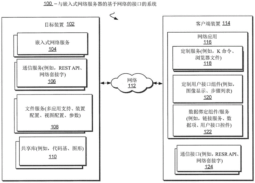
Fig. 1 is a block diagram of an embodiment of a system or framework 100 for a web-based interface with an embedded web server. The system 100 includes a target device 102, such as a machine vision camera or other data acquisition device, in communication with a client device 114 over a communication network 112, such as ethernet, TCP, HTTP or other such communication networks, including the internet, such as the internet.
In one embodiment, the target device 102 provides the embedded web service 104 to allow a web-enabled device (e.g., client device 114) to access a set of web pages or web applications that process and/or display data generated by the target device using the network 112.
The target device 102 further provides communication services 106, such as REST APIs (representational state transfer application programming interface) and web socket interfaces. The REST API allows the client device 114, including the web application 116 on the client device, to invoke functions that reside on the target device 102. The function may return a data file residing on the target device 102, including data representing an image acquired by the target device 102.
In one embodiment, the network socket interface provides a TCP (transmission control protocol) socket type connection between the internet enabled devices (e.g., devices 102 and 114) and the network service 104 and network application 116 as will be described in further detail. A web socket type connection allows the target device 102 to push data in real-time to a web application 116 operating on the client device 114.
In one embodiment, the target device 102 further provides a file service 108 and a shared library 110. The file service and shared library supports access to configuration and configuration parameters of the target device, and also supports access to a shared library of code and graphics assets by one or more network applications.
The target device 102 is typically a dedicated device, such as a camera, scanner, or other type of data acquisition and/or process control device. The target device 102 may also include a 1D or 2D barcode reader (imager) or authentication and verification device, an image acquisition device of a machine vision system, a laser scanner, an RFID reader, and the like. In the context of an image acquisition device of a machine vision system, the target device 102 may include a machine vision camera, such as a smart camera or other camera having connectivity with the machine vision system.
Client device 114 is generally any web-enabled device, ranging from a fixed desktop computer or other HMI device having a browser interface and network or Internet access, to any of a variety of mobile devices (e.g., smart phones, laptops, tablets, and PDAs) having a browser-based display interface and network access.
The client device 114 is typically configured with a web application 116 that allows the client device 114 to access the embedded web service 104 of the target device 102. In particular, the web application 116 provides a customization service 118 and a User Interface (UI) component 120, the UI component 120 allowing a user of the client device 114 to view, monitor, and/or control processes performed by the target device 102.
To support the customization service 118 and the UI component 120, the web application 116 further provides a data binding component/service 122 to facilitate binding of data objects in the web application 116 with corresponding data items or controls in the shared library 110 used by the embedded web service 104 and the file service 108 on the target device 102.
The client device 114 is further provided with various communication interfaces 124 that support communication protocols used by the corresponding communication service 106 of the target device 102 to transmit data, including binary data and text data.
FIG. 2 illustrates a typical operating environment for an embodiment of a data acquisition system 200 that supports a network-based interface with an embedded web server, as in FIG. 1. Target devices, such as machine vision cameras a 1-A3, or other types of data acquisition devices, such as scanners, are coupled to computer a in a daisy chain configuration, and machine vision cameras B1-B3 are coupled to computer B, such as a laptop computer, in a bus configuration. Computer a is coupled to computer B by a communication link (e.g., ethernet, TCP, HTTP or other such connection). A server C, such as a server computer serving as an intermediate network accessible server C that facilitates communication between computer a, computer B, cameras a 1-A3, and any one or more of B1-B3, is coupled to both the camera and the computer by a communication link, such as ethernet, TCP, HTTP, or other such connection.
In various embodiments, the computer may operate in a stand-alone configuration with a connection to one or more machine vision cameras and a server computer in the data acquisition system. In an operating environment, the communication links between components may be wired, wireless, or some combination of the two. In particular, a mobile computer, such as computer B, may communicate with other components of the system using a connection to the internet or through a wireless access point with a communication link.
In the context of the data acquisition system 200, the data generated by the barcode scanner and camera is typically generated in a periodic manner, and ranges from simple decoded strings to more complex data, such as calibrated measurements and sets of images captured by the camera. Each "read cycle" or "verify cycle" generates a "cycle report" containing pertinent information about the operation of a single cycle.
For example, a read cycle may contain, among other information, decoded output strings, timing information, position information (which may be used to draw graphics). Both the scanner and the data acquisition system employing the camera also process images that represent information that is itself very useful.
In typical operation of a scanner or camera in a data acquisition system, a single cycle report may relate to multiple images. The image may also be quite large. Thus, it may not be possible to simultaneously transmit image information from the target device 102 to the client device 114, or to use the same transmission means as used for transmitting the recurring reports. In particular, the network connections through the network 112 support communication services 106 and communication interfaces 124 that are generally oriented to one type of data (i.e., binary or text) or another type (but not both). This may result in the transmission of two different data streams involving a single cyclic report: one for report data and one for images.
Since two different data streams are typically transmitted asynchronously, they need to be correlated in order to display an overlay on the image, e.g. based on information from a loop report. In one embodiment of an embedded web server on the target device 102, the loop report data used to generate the overlay may be pushed to the client device 114 via a web socket 106, for example, described using a data synchronization service described in further detail in FIG. 6, requiring the image data itself to be requested at regular intervals to refresh the HTML < img > tag corresponding to the display of that image.
For example, in the overlay example, the embedded web server 104 on the target device 102 generates a loop-containing report that contains a list of unique ids (uids) for each image used to generate the loop report. The image itself is buffered on the target device 102 for a limited time or for a longer duration on the client device 114 or other device to which the target and client devices have access. After the loop report is received and parsed by the web application 116, corresponding image data representing the image is extracted using the UID as part of an image source URL (uniform record locator) that references the corresponding image data transmitted from the target device 102. Corresponding superimposition data for superimposing an image is correlated with image data. In this manner, the web application 116 operates in conjunction with the embedded web service 104 to correlate overlays with image data transmitted from the target device 102 to the client device 114, as required by the limitations of the available communication channels between the devices.
To efficiently access the data, information data generated by the camera that acquired the image data may be encapsulated and sent to a web application on the client using a standard communication protocol. For example, in one embodiment, during a read cycle of the camera, the embedded web server packages information about the acquired images and/or data into a read cycle report and transmits the report to the client device 114 using a standard communication protocol provided by the communication service 106 of the target device 102.
In one embodiment, for certain target devices 102 and client devices 114, the read cycle reports generated by the target 102 are encapsulated using XML (extended markup language) or other standard data protocol and transmitted to the client 114 over a web socket interface supported by the respective communication services/interfaces 106/124 of the devices. Once received by the client 114, the web application 116 processes the data contained in the read cycle report by referencing the tags and attributes of the XML read cycle report back to the corresponding data on the target device 102.
In one embodiment, the data referencing is performed in the client device 114 using a data binding component service 122 of the client of the network application 116 that communicates with the corresponding file service 108 and communication service 106 supporting the embedded network service 104 on the target device 102. In one embodiment, the data referencing function may be implemented as a linking service as described in further detail with reference to FIG. 5.
FIG. 3 illustrates an embodiment of selected subsystems of a data acquisition system as in FIG. 1 that supports a network-based interface with an embedded web server. For example, the target device 102 may contain numerous actual subsystems that are complex and operate non-sequentially and non-intuitively from the vantage point of a user of the web application 116 user interface on the client device 114. To provide more efficient access to data and information generated by the target device 102, in one embodiment, the web application 116 is configured to convert non-intuitive and non-sequential control flows into linear logical control flows. In the illustrated example, the linear logic control flow is embodied in a virtual subsystem represented as a list or sequence of logic steps 304, the list or sequence of logic steps 304 including loop steps, camera steps, decode steps, match steps, and output steps.
In one embodiment, any one or more steps in the step list 304 may be configured to generate virtual high-level parameters from a plurality of process parameters in an actual subsystem for the target device 102. By way of example only, in fig. 3, the virtual subsystem 304 represents a read cycle in which a single high-level cycle parameter exposed to the user interface corresponds to three process parameters that control the operation of the target device 102, specifically, the qualifier parameter 306, the Xmode parameter 308, and the match control 310 parameters. In other embodiments, the virtual subsystem of the web application 116 on the client device 114 may include other high-level parameters corresponding to different process parameters that control the operation of the target device 102.
Fig. 4 a-4 b illustrate an overview of an embodiment of an embedded web server operating environment and a process for supporting a web-based interface with an embedded web server in such an operating environment. As mentioned previously, embedded web servers operate under certain constraints on memory, storage, bandwidth, and CPU cycles. In addition, the demand for network services provided by embedded servers is increasing due to the availability of network access. The operational scenario 400 in fig. 4 a-4 b illustrates typical requirements for an embedded web server in the data acquisition target device 102.
Fig. 4a further illustrates a process 418 on the target device 102 for generating relevant historical data for the web application 116 user interface of the client device 114, according to one embodiment. As will be explained in further detail in this application, the relevant historical data may be particularly useful for testing the network application 116 and the target device 102 under controlled operating conditions, or for use during setup, or for optimally controlling the timing and other parameters of the operation of the target device during data acquisition cycles.
According to one embodiment, and FIG. 4b further illustrates an embodiment of a process 422 on the target device 102 for adjusting thread priorities to enhance the responsiveness of the embedded web server 104 and the web application 116 during tasks such as setup and testing.
Referring to FIG. 4a, during embedded web server processing 416, five different asynchronous events 402 representing a web server request E1, a parameter change E2, and three different data requests E3, E4, and E5 occur at various points within the process of the data acquisition timeline 412. An event generally represents an external request originating from a web application 116 User Interface (UI) client 114 to access data acquired and/or generated by a target device 102.
In addition, two different triggers: trigger # 1404 a and trigger # 2404 b each represent an event on the target device 102 itself that triggers the target device to begin processing the respective data acquisition cycles 406 a-406 c and 406 d-406 f. Each data acquisition cycle is characterized at the end of a variable duration previous stall period 406a/406b, followed by a fixed duration acquisition period 406b/406e, followed by a variable duration processing period 406c/406 f. Each data acquisition cycle ends with the generation of a data packet 408a/410a, after which the target device 102 enters another stall period until the next trigger occurs.
In one embodiment, the embedded network server 104 of the target device 102 generates relevant historical data 418, which includes the data packets 408a generated at the end of the data acquisition cycles 406 a-406 c and any corresponding performance information 408b and parameters 408c that were in effect during the time 412 of the data acquisition cycle. In this manner, the embedded network server 104 of the target device 102 provides data coherency 408 to the network application 116 that receives the data packet 408 a. The data coherency 408 is useful for setting, testing, and optimizing the operation of the target device 102.
In the illustrated embodiment, the process of generating the relevant historical data 418 is repeated for the next data packet 410a generated at the end of the data acquisition cycle 406 d-406 f and any corresponding performance information 410b and parameters 410c that were in effect during the time 412 of the data acquisition cycle. Coherent data 408/410 may be accumulated and stored on target device 102 for a limited time and transmitted to other devices in communication with target device 102, including client device 114, for longer term storage and availability of network applications 116 to client device 114.
FIG. 4b illustrates the same operational scenario as in FIG. 4a, and further illustrates an embodiment of a process 422 on the target device 102 for adjusting thread priorities to enhance responsiveness of the embedded web server 104 to the web application 116 during tasks such as setup and testing, or during normal operation.
In one embodiment, the target device 102 is configured with a hierarchical priority of acquisition processes in order from high to low, i.e., image acquisition or other data acquisition, confirmation events, including external asynchronous events 402 and trigger events 404a/404b, data processes for processing images and/or other data acquired or received by the target device 102, and processes for handling the aforementioned events.
In a typical environment, a default level priority must facilitate acquisition of the target device 102 by satisfying the acquisition and event confirmation process prior to the data processing and event handling processes. This is necessary because the target device 102 cannot delay data acquisition due to the temporal nature of acquisition, i.e., the target device 102 has only one window of opportunity to acquire images or obtain data. The same is true of event validation, which must be performed upon receipt of an event.
However, in one embodiment, the adjusted hierarchical priority may temporarily favor client device 114 by reversing the priority of the data processing process and the event handling process under certain conditions.
For example, as illustrated in fig. 4b, after the acquisition process 406b is completed in response to the trigger # 1404 a, and after the two asynchronous events 402 (web server request event E1 and parameter change event E2) are acknowledged, the target device 102 begins the normally delayed processing of event E1 during the stall period 406 d. Thereafter, in one embodiment, the target device determines either explicitly from information provided by the client 114 or other user, or implicitly from the type of asynchronous event 402 that has been confirmed so far: the user experience should temporarily override the data processing process.
For example, an explicit determination may be the result of receiving data, i.e., the client is performing a setup sequence prior to data acquisition. Alternatively, the implicit determination may be the result of receiving a sequence of events that suggests that the client is performing a setup or test sequence prior to data acquisition. Either way, once the determination is made, the target device performs a priority reversal process 422 to temporarily increase the priority of the processing time above the priority of the processing of the data.
As a result of the priority reversal process 422 being performed, in one embodiment, the target device 102 now temporarily benefits the client device 114 and the user experience by continuing process events E1 and E2 (despite receiving the second trigger # 2404 b). The target device 102 completes processing of events E1 and E2 simultaneously while performing the second acquisition process. Upon confirmation of the third event E3, the fourth event E4, and the fifth event E5, the target device 102 immediately processes each of the events and preempts the data processing that would otherwise take priority. Thus, instead of waiting to process the data request events E3, E4, and E5 until the next stall period (after generating packet # 2), the target device 102 is able to immediately respond to the requestor (i.e., one or more clients 114 and web applications 116) with the requested data of events E3, E4, and E5.
In one embodiment, by temporarily favoring one or more client devices 114, the embedded web server 104 of the target device 102 is able to be more responsive to the one or more client devices 114 without negatively impacting the acquisition and event validation process, which must always remain at the highest priority because it cannot be delayed.
Fig. 5 illustrates an overview 500 of an embodiment of selected communication services of a data acquisition system that supports a network-based interface with an embedded web server, as in fig. 1. The communication service includes a link service 502 that interoperates between the target device 102 and the client device 114 over the network 112. In one embodiment, the linking service 502 may be implemented as an intermediate service on a shared server that communicates with both the target device 102 and the client device 114.
The link service 502 supports the embedded server link service 104 deployed on the target device 102 and the corresponding web application link service 122 deployed on the client device 114, where symbolic identifiers, link IDs 504 may be used to reference the link objects 506a/506b to perform object data value syncs 508a/508b between the link object's data values 506b and the link objects 506a on the target device 102 in a unified manner regardless of the data source 108/110. In one embodiment, object data value synchronization 508a/508b is performed by automatically transmitting/pushing any object data value changes 508a originating from the target device 102 to the client device 114, and vice versa. An example of object data value synchronization is described in further detail with reference to fig. 6. The link object 506 on the client device 114 corresponds to a data binding control 512 for the bindable data item 510 or resident on the target device 102.
In the context of a data acquisition system, among other advantages, the linking service 502 operates in conjunction with the web application 116 on the client device 114 to facilitate remote monitoring of active verification performed in real-time by a camera of the target device 102 of the data acquisition system.
For example, once received at the client device 114, the loop report described above is converted into a link object 506. The loop report itself is represented as a link object 506, as are any of the referenced data items within the loop report.
In one embodiment, the bindable data items 510 and data-binding controls 512 (to which the link object 506 corresponds) include, but are not limited to, the aforementioned read cycle reports, K-commands (scanner configuration commands), counters, metrics, diagnostic data, image and image display controls, step list display controls, data and device information display controls, and various types of widgets. Additional details of an exemplary bindable data item 510 and data binding control 512 (to which the link object 506 corresponds) are listed in FIG. 13.
In one embodiment, the bindable data items 510 and data-binding controls 512 are defined not only by specifying the type of item or control, but also by provisioning properties (e.g., defining the title and display format of the display of the item or control). In addition, a linking service, such as linking service 502 described above with reference to FIG. 5, is specified.
FIG. 14 illustrates an example embodiment of a definition of a data binding control 512, such as a widget that displays a bindable data item 510 that is referenced using the linking service 502. In the illustrated example, the linking service 502 is triggered when the network application 116 encounters the identifier "mslink" followed by a symbolic identifier. The symbolic identifier is an identifier that was previously associated with the corresponding bindable data item 510 or control 512 on the target device 102 such that it can be accessed in a uniform manner regardless of the data source 108/110. Each of the instance definitions results in a data-binding component 122 for the corresponding bindable data item 510 and/or data-binding control 512.
Fig. 6 is a block diagram of an embodiment of an object data value synchronization service 600, the object data value synchronization service 600 for synchronizing parameters 602 on a target device 102 with corresponding proxy parameters 614 on a client device 114 of a data acquisition system supporting a network-based interface with an embedded web server, as in fig. 1. To name an example only, the description is for parameters; of course, the synchronization process of the service 600 may be used to synchronize any data object having a value object definition on the target device 102 with a corresponding proxy object on the client device 114.
In one embodiment, at least two communication channels 608 and 612 are established between the target device 102 and the client device 114. In addition, both the target device 102 and the client device 114 are configured to exchange data according to a standard non-proprietary data protocol, such as JSON or XML. In the illustrated embodiment, a web application on the client device 114 requests a value object definition 604 for a set of parameters X, Y, W and H using a REST or MIXL request using the first communication channel 608. In response, the target device 102 transmits the value object definition 604 to the client device 114 over the second communication channel 610 using a standard data exchange protocol (e.g., JSON or XML).
In one embodiment, upon receiving the value object definition 604, the web application 116 on the client device 114 may generate a viewport or other UI component for displaying the proxy parameter object data value 614, as described in fig. 5 and as will be further described with reference to fig. 7. Once displayed, the object data values 614 reflect the actual values of the parameter fields 602 on the target device 102.
In one embodiment, the target device 102 generates a change notification of any value object change 606 with respect to the value of the parameter field 602. Using the separate communication channel 612, the target device 102 may then effectively push the change notification 606 to any client device 114 requesting the value object definition 604 of the parameter field 602 to ensure that the most recent values of the parameters on the target devices 1-2 are reflected in the client device 114 web application 116UI in real-time or near real-time.
FIG. 7 illustrates an embodiment of a link services process flow 700 for a web-based interface with an embedded web service as described in FIG. 1. Among other functions, the link service process 700 parses symbolic identifiers previously associated with data on the target device 102 so that they may be accessed in a uniform manner regardless of the data source 108/110. The process 700 begins with receiving a symbol identifier at 702. In one embodiment, the process 700 also receives an object identifier at 702, where the object identifier is used to resolve the symbolic identifier.
Table 3 summarizes the different types of data that may be represented by symbolic identifiers in one embodiment.
TABLE 3 example data types represented by symbolic identifiers


The symbol identifier is comprised of a string of characters, and at 704, the process 700 determines the type of data represented by the symbol identifier based on the first character of the string of characters. Thus, in one embodiment, using the example data types listed in Table 3, a symbolic identifier having a "K" in the first character of the string represents a parameter of the "K" command; "@" indicates an item within the most recent cycle report generated by the target device; and "$" represents an item within a reusable and self-contained code segment.
In one embodiment, the process 700 continues at decision 706 to identify the supported data types, and at 708 selects which service or object to use as a basis for resolving symbolic identifiers of the supported data types.
In one embodiment, when the symbol identifier contains a "$", the process 700 also typically receives the aforementioned object identifier or object ID at 702. Which is such an object that contains reusable and self-contained code segments that contain the items represented therein. The process 700 locates the represented item by matching the remaining string with the name of the item contained in the object.
In one embodiment, the named object or object ID containing reusable and self-contained code fragments is defined as a service component of the AngularJS development framework and is referred to as the angulars service.
For example, in one embodiment, to resolve the symbol identifier "$ targetInfoService. targetIPaddr", the AngularJS $ objector service is used to find the service name represented by targetInfoService. This service name is combined with the remainder of the symbolic identifier, resulting in an expression that can be evaluated to obtain the value of the term contained within the angularJS service. The sample code for implementing the process is as follows:
var serviceName=“targetInfoService”;
var reference=“targetIpAddr”;
var service=$injector(serviceName);
var expr=“service.”+reference;
var value=eval(expr);
in one embodiment, once the symbolic identifier is resolved, the process 700 establishes a link between the data of the target device 102 and the corresponding data displayed in the web application 116 on the client device 114 at 710. At 712, process 700 continues to maintain synchronization of the value of the data on the target device with the corresponding data on the client device for the remainder of the verification activity performed by the target device. For example, at 712, process 700 may perform object data value synchronization 600 described in fig. 6 to push value object change notification 606 to client device 114.
In one embodiment, the linking service 502 and the corresponding web application linking service 122 of the data binding component deployed on the client device 114 can be implemented in one or more methods of the customization service 118 of the web application 116. The service 118/122 is typically composed of reusable and self-contained code segments, such as the code segment contained in the aforementioned AngularJS development framework and referred to as the Angularservice.
An exemplary method of an embodiment of the linking service 502 is summarized in Table 4, where the term "mslinkId" refers to the symbolic identifier link ID 504a/504b, and the term "mslink" refers to the link object 506a/506b (FIG. 5).
TABLE 4 example method of linking services


Notwithstanding the above examples, it should be understood that any data object or control within the web application 116 user interface may be capable of becoming a link object 506a/506b, which corresponds to a bindable data item 510 or data binding control 512 on the target device 102, and which is accessible on the client device 114 via the link service 502. For example, data objects and controls in the web application 116 may correspond to certain target devices 102, client devices 114, and/or other system or user settings unrelated to read cycle reporting.
In one embodiment, because read/write access to each data item and/or control is facilitated using linking service 502 (FIG. 5), the history of changes to the data items and controls over time may be stored for future access, as described with reference to the relevant history data 418 (FIG. 4a) and further with reference to object data value synchronization (FIG. 6). Advantageously, the stored history of changes permits a user of the web application 116 on the client device 114 to view the history of changes to any data value stored, including data representing the image and controls that relate the image to all other bindable data items 510 or data binding controls 512 (FIG. 5) that are in effect at the same time.
As an example, finding the optimal set group on the target device 102 that maximizes the performance and robustness of the inspection work performed by the target device 102 in the data acquisition system 200 may typically require a trial-and-error approach. However, using a client device 114 operating in conjunction with a target device 102 according to the described embodiments, a user of the web application 116 on the client device 114 may view a UI display of various graphics of the performance information 408b and parameter values 408c validated at various points in time 412 (fig. 4b) to quickly find the optimal set group.
In one embodiment, the client 114 web application 116UI may be configured to display the stored corresponding history values (decode character strings, etc.), image slides and other displayable data items, and data controls depicting data from the target device 102 at a point in time, alongside the display of various graphics. The user may browse the graphic and select a value on the graphic that is displayed to the user indicating the moment at which the conditions on the target device 102 that affect the performance and robustness of the inspection job are optimal.
In one embodiment, upon receiving a value selection by a user that appears optimal, the client UI displays other information that is in effect at the same time, such as images, parameters, settings, recurring reporting data, and other performance data. From this client 114 web application 116UI display, the user can then select the optimal set-up group for use by current and future inspection jobs. The user can repeat the selection process as needed to ensure that inspection performance and robustness are maximized.
In one embodiment, the stored values' associated historical data 418 (FIG. 4) and other information (e.g., images, parameters, settings, cycle report data, and other performance data), while determined to be in effect at the same time, may or may not actually be generated at the same time, or even made available via the same communication service/communication interface.
The above-described features associated with the use of the link service 502 and the link objects 506a/506b, including facilitating access by the client 114 to the bindable data items 510 and bindable data controls 512 on the target device 102, and facilitating performance analysis and optimization by storing a history of changes to the link objects 506a/506b over time, are also useful for facilitating testing and external control of the data acquisition system.
In one test scenario, the automated UI test application may set the values of the link objects 506a/506b directly to simulate certain conditions of the verification job, such as if the user changes a setting or value within the web application 116UI on the client device 114 is received via a recurring report generated on the target device 102. In addition, if the automated test detects a problem with the inspection work, the problem can be correlated with all the information that was also in effect at the time the problem occurred.
FIG. 8 illustrates an embodiment of a User Interface (UI) component hierarchy of a data acquisition system supporting a web-based interface with an embedded web server as described in FIG. 1. To take advantage of the standardization of network technologies, embodiments of a network-based interface with an embedded network server employ a hierarchy of user interface components 800 that facilitate the layout of a customized user interface.
The framework component 802 is the outermost structure of the UI, which consists of the banner region, status bars, and the general layout and style of the web application 116. Overlay component 804 includes alerts, dialog boxes, windows, help bubbles, and other graphical components that are overlaid on the display of other content of page 806 during operation of web application 116 as desired.
The page component 806 defines the primary content of the web application 116. In one embodiment, each page is constructed from a page template, a separate element of AngularJS-enabled HTML (HyperText markup language). The resulting page is referred to as an example of the AngularJS indication or the view indication. During operation of the web application 116, a desired page is typically selected via a navigation control, such as an arrow button displayed in a banner display in the frame component 802. In one embodiment, multiple buttons may share the same page template, but with different options selected. For example, three arrow buttons displayed in the banner of frame 802, such as start, set, and run buttons, may all share the same page template, but will display different content and/or options to the user.
In one embodiment, the remaining views 808, panels 810, and widget 812UI components are constructed from the aforementioned view indications. During operation of the web application 116, the view indication displays the view 808 created by interpreting the view definition file 814. The view definition file 814 contains a description of the layout of the view 808 as one or more panels 810, each of which contains a widget array 812.
In one embodiment, the description of the layout is implemented as one or more JSON objects that have properties that define the layout of the panel 810 and widget 812. Each panel 810 defines a rectangular area of the view 808. The boundaries of the panel 810 may be set with style sheet functionality, such as CSS (cascading Style sheet) style sheet language. An example of the properties of a JSON object from which view 808 can be created is summarized in table 5.
TABLE 5 example Properties of JSON objects from which views are created

The description of the layout contained in the view definition file 814 typically includes attributes 816 and widget definitions 818, which control the appearance of the view 808, panel 810, and widget 812UI components. The widget UI component 812 is a self-contained functional unit such as the step list, image display, and chart widget described in Table 2.
An example of attributes 816 that are applicable when creating a view is summarized in FIG. 15.
FIG. 9 illustrates an embodiment of a process 900 for constructing the view 808 (FIG. 8) of the network-based interface 116 with the embedded web server 104 as described in FIG. 1. The process 900 begins at 902, where a view indicates that a view definition file 814 (FIG. 8) is received. At 904, the view indicates that any symbolic identifiers representing bindable data items that may be present in the view definition file are parsed using linking service 502 (FIG. 5). At 908, the view indication determines whether there are any data binding controls, such as widget definition objects present, and if so, continues at 910 to resolve any symbolic identifiers representing bindable data items contained in the data binding controls. The process 900 continues at 910 to generate a UI control from the data binding control, e.g., a widget UI control from a widget definition.
At 912, once any widget UI controls are generated, the view indicates the application of properties to the values of the data items and the generated widget as defined in the view definition file. After the properties are applied, at 914, the view indicates the panel defined in the generate view definition file.
The process 900 ends at 916 by defining the style sheets defined in the file by the application view, and finally by constructing 918 the view from the generated panels and widgets and style sheets and properties of the application.
FIG. 10 is an illustration of an embodiment of a view user interface of a data acquisition system such as that in FIG. 1 that supports a web-based interface 116 with an embedded web server 104. By way of example only, FIG. 10 illustrates a view user interface 1000 constructed for the web application interface 116 on the client 114. In one embodiment, view 1000 is constructed from a view definition file, as described with reference to FIG. 9. In the example illustrated in fig. 10, view 1000 includes: a left panel 1008 containing device information and step list UI components; a right panel 1012 containing a plurality of data widget components; and a center panel containing ip image UI components 1010, including image data acquired by the target device 102 and extracted by the web application 116 based on the UID supplied in the relevant recurring report. For display in the center panel, the image data may be overlaid with information about the image, such as the textual information "TestABC 123" 1014a/1014 b. In one embodiment, the view user interface 1000 includes "start" 1002, "set" 1004, and "run" selections to control the operation of the web application interface 116. In the illustrated embodiment, the displayed UI components are populated with instances of values for bindable data items and data-binding controls as described in FIG. 13.
Examples of bindable data items, data binding controls, and corresponding generated UI control components are further illustrated in FIG. 11. More specifically, by way of example only, FIG. 11 is an illustration of an embodiment of a step list UI component 1100 that may be displayed, for example, in the left panel 1008 of the view user interface 1000 described with reference to FIG. 10. The step list UI component 1100 displays information contained in the cycle report and/or other data related to the data acquisition cycle and further related to the image data currently on display in the center panel 1010 of the view 1000.
In the example of the step list UI component 1100 in FIG. 11, the symbolic identifiers of TRIGGER _ MODE, NUM _ SYMBOLS, END _ CYCLE _ MODE, and END _ CYCLE _ TIMEOUT are each parsed into their corresponding data item values using the linking service "mslink," and the resulting values are formatted for display in accordance with the graphical display controls in the step list UI component 1100.
Another example of a bindable data item and data-binding control is an image-defining object, referred to in FIG. 13 as an "ip image" type of display control, some examples of which are illustrated in the center panel of the view in FIG. 9. In general, embodiments of the ip image control display one or more images acquired by the target device 102 and any associated image processing data. The image processing data may include the location and boundaries of objects identified within the image, performance data, and other graphics associated with the image, including overlay data to be overlaid on the image.
In one embodiment of the data acquisition system, for a target device 102 that includes an image sensor-based product, a corresponding image display control for displaying an image, such as the "ip image" type of display control described above in FIG. 13, controls the display of a single inspection image and any associated data and graphics. This display may be updated quickly to show a "real-time" display of the inspection process. It is also common to display a history of such images in a "slide" display control, each frame representing a previous inspection or reading result. The slides show the individual images evenly spaced as if they were frames on a camera film.
An example of this type of display control is illustrated in fig. 12A, where an image display control operating in a mode referred to as "single mode" displays a single image 1202, along with any associated image processing information.
However, many applications require multiple images to achieve a single result. A common reason is that the product to be inspected is physically larger than the product that can be captured within the field of view of a single sensor. This is solved by using multiple sensors or by physically moving the sensors or the product. In this scenario, the image display control operates in "multi-mode" as illustrated in FIG. 12B to control the display 1204 of multiple images, showing historical information or displaying groups of images that are all used to produce a single result.
There are also situations in which multiple images are acquired at the same production location to improve the robustness of the inspection or decoding operations performed by the data acquisition system. In this case, each image is acquired at the same location but at a different time. When setting up these types of applications, timing can present challenges that cannot be addressed by single and multi-modes of image display controls.
For example, in one embodiment illustrated in fig. 12C, multiple images of the circuit board 1206 moving through the image sensor are shown from left to right. In this example, the circuit board 1206 is not completely covered with an image, as evidenced by gaps 1208a and 1208b between the first, second, and third images of the board. In this scenario, it is desirable to acquire images at a fully accurate speed to most effectively cover the entire sheet as it travels along the path of the field of view of the acquisition device.
If the display of FIG. 12C is updated "in real time", then adjusting the delay will be straightforward until full coverage (or partially overlapping coverage) is achieved. For example, gaps between images may be corrected by adjusting inter-image delay settings on the target device, possibly through the use of slider range UI controls (not shown). The challenge is to set the acquisition timing so that the board is adequately covered for processing. This becomes particularly challenging if all timing and size information is not known in advance. Therefore, finding the correct image acquisition speed may typically involve trial and error.
In one embodiment, to assist in the setting of time-sequential related applications, the image display control operates in a time-scale mode by managing the display of images using a time scale. For example, imagine that a sensor can acquire 1000 pixels wide images every 50 ms. The display of the image may be time scaled such that each cell in width may represent 50/1000-1/20 of milliseconds. As multiple images are captured, precise timing information relative to the start of the sequence is maintained.
In the time scale mode, the image display control translates this precise timing information along the time axis to a visual interval of the plurality of images within the image display control, also referred to as displaying the time scale image. In this manner, the time scale mode operation of the image display control provides useful information to the user to visualize and diagnose timing issues with the operation of the target device 102, or to set a complex triggering scenario that initiates a data acquisition cycle, as illustrated in fig. 4a/4 b.
For example, in the example illustrated in fig. 12C, the timeline may be represented in a graphical overlay, or otherwise integrated into the image display control. As shown, a time axis is represented as a time-stamped arrow graphic 1210 to indicate the timing associated with the image of plate 1206 as plate 1206 travels through the field of view of the camera.
Another example of using a time scale display mode of operation in an image display control would be to detect timing jitter. For example, in one embodiment, as illustrated in FIG. 12D, three images are required for each read cycle output, and each row in the display represents a single read cycle. The first image within each cycle is captured simultaneously using a trigger, resulting in all images in the first column 1212a being positioned flush on the left side of the display. The subsequent two images of each read cycle are spaced apart in time relative to the trigger and positioned accordingly on the display.
In the above scenario, if the timing is accurate, the images will be displayed aligned in the exact columns. However, in this example, the timing is not so accurate, and that is evident in the display, where the images in the second and third columns 1212b and 1212c are irregularly positioned on the display. In one embodiment of the image display control, this resulting image "jitter" may be corrected by adjusting the inter-image delay, possibly by using a slider range UI control and repeating the adjustment until the image display control displays the second and third columns in proper alignment.
As another example of using an image control display in a time control mode, the time scale image display described above is combined with a more traditional timing diagram as shown in the display illustrated in FIG. 12E. In one embodiment of the time-controlled mode operation of the image display control, the display 1214 of the plurality of images of plate 1206 includes a first timing signal 1218, i.e., the image display control overlays the image of plate 1206 to clearly show the timing of the image acquisition.
Alternatively or additionally, embodiments of the image display control may display one or more other timing signals. For example, referring again to fig. 12E, the image display control may display timing signal 1216 and timing signal 1220 in parallel with the image of plate 1206 and first timing signal 1218. In this way, the image display control is able to show the timing of image acquisition relative to the other timing signals 1216, 1220.
In one embodiment, the display of timing signals 1216, 1220 is triggered by a combination of events and displays timing information derived from various sources, including timing information 1218 associated with the time-scaled image itself.
The above description of illustrated embodiments of the invention, including what is described in the abstract of the specification, is not intended to be exhaustive or to limit the invention to the precise forms disclosed. While specific embodiments of, and examples for, the invention are described herein for illustrative purposes, various equivalent modifications are possible within the scope of the invention, as those skilled in the relevant art will recognize. These modifications can be made to the invention in light of the above detailed description.
The terms used in the following claims should not be construed to limit the invention to the specific embodiments disclosed in the specification and the claims. Rather, the scope of the invention is to be determined entirely by the following claims, which are to be construed in accordance with established doctrines of claim interpretation.
Claims (21)
1. A device for acquiring an image of a barcode or two-dimensional code, comprising:
imager and embedded web server, wherein:
the imager is configured to:
(i) acquiring an image of a bar code or a two-dimensional code;
(ii) generating data including a decoded character string from the acquired image; and
(iii) storing the generated data in a memory on the device; and
the embedded web server is configured to:
(i) connecting to a remote client device via a communication network;
(ii) receiving a request for the generated data from the remote client device; and
(iii) transmitting the requested generated data to the remote client device for display on the remote client device.
2. The device of claim 1, wherein the generated data stored in the memory is accessible from a web application running on the remote client device.
3. The apparatus of claim 1, wherein the memory stores a plurality of decoded strings corresponding to the acquired image.
4. The apparatus of claim 1, wherein the generated data comprises encoded image data representing the acquired image.
5. The device of claim 1, wherein the generated data comprises text data related to the captured image such that the remote client device can simultaneously display the captured image and the text data on the same screen.
6. The device of claim 5, wherein the associated text data causes the remote client device to simultaneously display the acquired images overlaid by the text data.
7. The apparatus of claim 1, wherein the generated data comprises graphical data and/or numerical data.
8. The apparatus of claim 1, wherein the generated data comprises status data indicating a status of the apparatus at a time the acquired image was acquired.
9. The device of claim 1, wherein the generated data comprises settings data such that the remote client device can display settings of the device while displaying the acquired image.
10. The apparatus of claim 1, wherein the generated data comprises a success/failure indicator indicating whether decoding of the acquired image was successful.
11. A method of monitoring an acquired image of a barcode or two-dimensional code, executing on an image acquisition device having an image sensor, one or more processors, and memory, wherein the memory stores an embedded web server and one or more programs, wherein the one or more programs include instructions for performing the processes of:
acquiring an image of a barcode or a two-dimensional code using the image sensor;
generating a decoded character string corresponding to the image and storing the decoded character string in the memory;
receiving, on the embedded web server running in the memory, a request from the remote client device for information relating to the acquired image; and
in response to the request, transmitting the requested information about the acquired image to the remote client device for display on the remote client device.
12. The method of claim 11, wherein a recurring report corresponding to the image is generated and transmitted to a remote client device over a communication network.
13. The method of claim 12, wherein:
the recurring report including, for each of a plurality of images, a respective image identifier, the plurality of images including the acquired image;
the request from the remote client device specifying the acquired image using a corresponding image identifier; and
the transmitted information includes image encoding data corresponding to the acquired image.
14. The method of claim 13, wherein the plurality of images are acquired during a processing cycle and the cycle report is generated after accumulating the plurality of images during the processing cycle.
15. The method of claim 14, wherein each of the plurality of images represents a respective portion of a scene, and further comprising stitching the plurality of images together to form a single larger image representing the scene.
16. The method of claim 14, wherein the plurality of images are captured sequentially as one of the image acquisition device or the scene traverses a straight-line path.
17. The method of claim 11, wherein transmitting the requested information to the remote client device uses two or more different communication channels of the communication network simultaneously.
18. The method of claim 17, wherein the image data is transmitted on a first communication channel and the non-image data is transmitted on a second, different communication channel.
19. The method of claim 18, wherein the non-image data is temporally correlated with the image data such that the remote client device can display the acquired image overlaid with temporally correlated non-image data.
20. The method of claim 11, wherein the requested information includes (i) image data representing the image and (ii) non-image data temporarily related to the image data, the non-image data including one or more of: text data, graphics data, numerical data, a status of the image acquisition device, setting data for the image acquisition device, and a success/failure indicator indicating whether decoding of the acquired image was successful.
21. A system, comprising:
an apparatus for acquiring an image of a barcode or two-dimensional code, comprising:
imager and embedded web server, wherein:
the imager is configured to:
(i) acquiring an image of a bar code or a two-dimensional code;
(ii) generating data including a decoded character string from the acquired image; and
(iii) storing the generated data in a memory on the device; and
the embedded web server is connected to a remote client device via a communication network;
wherein the remote client device is configured to receive the generated data from the embedded web server and display the generated data, the generated data comprising image data and non-image data related to the image data, the non-image data comprising one or more of: text data, graphics data, numerical data, a status of the image acquisition device, setting data for the image acquisition device, and a success/failure indicator indicating whether decoding of the acquired image was successful.
Applications Claiming Priority (3)
| Application Number | Priority Date | Filing Date | Title |
|---|---|---|---|
| US201562145401P | 2015-04-09 | 2015-04-09 | |
| US62/145,401 | 2015-04-09 | ||
| CN201680027123.1A CN107637048B (en) | 2015-04-09 | 2016-04-08 | Method, system and storage medium for an interface supporting Internet access for an embedded server |
Related Parent Applications (1)
| Application Number | Title | Priority Date | Filing Date |
|---|---|---|---|
| CN201680027123.1A Division CN107637048B (en) | 2015-04-09 | 2016-04-08 | Method, system and storage medium for an interface supporting Internet access for an embedded server |
Publications (1)
| Publication Number | Publication Date |
|---|---|
| CN112422629A true CN112422629A (en) | 2021-02-26 |
Family
ID=57072404
Family Applications (3)
| Application Number | Title | Priority Date | Filing Date |
|---|---|---|---|
| CN202011122785.1A Pending CN112422629A (en) | 2015-04-09 | 2016-04-08 | Embedded server's interface that supports Internet access |
| CN201680027637.7A Active CN107624241B (en) | 2015-04-09 | 2016-04-08 | Method, system, and computer-readable storage medium for embedded web server |
| CN201680027123.1A Active CN107637048B (en) | 2015-04-09 | 2016-04-08 | Method, system and storage medium for an interface supporting Internet access for an embedded server |
Family Applications After (2)
| Application Number | Title | Priority Date | Filing Date |
|---|---|---|---|
| CN201680027637.7A Active CN107624241B (en) | 2015-04-09 | 2016-04-08 | Method, system, and computer-readable storage medium for embedded web server |
| CN201680027123.1A Active CN107637048B (en) | 2015-04-09 | 2016-04-08 | Method, system and storage medium for an interface supporting Internet access for an embedded server |
Country Status (5)
| Country | Link |
|---|---|
| US (4) | US10182099B2 (en) |
| EP (3) | EP3281390B1 (en) |
| KR (2) | KR102450899B1 (en) |
| CN (3) | CN112422629A (en) |
| WO (2) | WO2016164847A1 (en) |
Families Citing this family (7)
| Publication number | Priority date | Publication date | Assignee | Title |
|---|---|---|---|---|
| CA2977359A1 (en) * | 2015-02-27 | 2016-09-01 | Level 3 Communications, Llc | Network address resolution |
| CN112422629A (en) | 2015-04-09 | 2021-02-26 | 欧姆龙株式会社 | Embedded server's interface that supports Internet access |
| KR20170028672A (en) * | 2015-09-04 | 2017-03-14 | 에스프린팅솔루션 주식회사 | Method for managing registry of image forming apparatus registered to cloud printing system, and cloud printing system for performing the same |
| US10404663B1 (en) * | 2016-02-29 | 2019-09-03 | Parallels International Gmbh | File sharing over secure connections |
| CN108830268A (en) * | 2018-05-28 | 2018-11-16 | 北京小米移动软件有限公司 | Content acquisition method, device, terminal and storage medium |
| CN109947542A (en) * | 2019-01-25 | 2019-06-28 | 上海倍通医药科技咨询有限公司 | The synthesis process scheduling method of data acquisition program |
| US11783073B2 (en) * | 2021-06-21 | 2023-10-10 | Microsoft Technology Licensing, Llc | Configuration of default sensitivity labels for network file storage locations |
Citations (9)
| Publication number | Priority date | Publication date | Assignee | Title |
|---|---|---|---|---|
| US20010029521A1 (en) * | 2000-03-29 | 2001-10-11 | Hiroshi Matsuda | Control method for image processing apparatus connectable to computer network |
| JP2007288617A (en) * | 2006-04-18 | 2007-11-01 | Kyocera Mita Corp | Image forming apparatus, user authentication system and method using the same |
| CN101149741A (en) * | 2006-06-29 | 2008-03-26 | 洛克威尔自动控制技术股份有限公司 | Automation HMI visualization utilizing GUI function blocks |
| CN101282272A (en) * | 2007-04-03 | 2008-10-08 | 佳能株式会社 | Remote instruction system, image forming device and control method |
| US20110009984A1 (en) * | 2009-07-09 | 2011-01-13 | Mukhi Sultan Q | Presenting dynamic scada data |
| US20110231774A1 (en) * | 2010-03-18 | 2011-09-22 | Konica Minolta Business Technologies, Inc. | Image processing apparatus, data processing method therefor, and recording medium |
| CN102289358A (en) * | 2010-06-15 | 2011-12-21 | 埃森哲环球服务有限公司 | A computer-implemented method, a computer program product and an embedded system for displaying data more efficiently |
| CN102713913A (en) * | 2009-10-14 | 2012-10-03 | 格里特康奈申股份有限公司 | Systems and methods for converting and delivering medical images to mobile devices and remote communications systems |
| US20140115101A1 (en) * | 2011-03-08 | 2014-04-24 | Gambro Lundia Ab | Method, control module, apparatus and system for transferring data |
Family Cites Families (178)
| Publication number | Priority date | Publication date | Assignee | Title |
|---|---|---|---|---|
| US6850252B1 (en) * | 1999-10-05 | 2005-02-01 | Steven M. Hoffberg | Intelligent electronic appliance system and method |
| KR0136671B1 (en) | 1995-04-14 | 1998-05-15 | 구자홍 | How to deal with VRF cancellation input |
| EP0825506B1 (en) * | 1996-08-20 | 2013-03-06 | Invensys Systems, Inc. | Methods and apparatus for remote process control |
| US5956487A (en) * | 1996-10-25 | 1999-09-21 | Hewlett-Packard Company | Embedding web access mechanism in an appliance for user interface functions including a web server and web browser |
| US6101407A (en) * | 1998-02-13 | 2000-08-08 | Eastman Kodak Company | Method and system for remotely viewing and configuring output from a medical imaging device |
| US7043532B1 (en) * | 1998-05-07 | 2006-05-09 | Samsung Electronics Co., Ltd. | Method and apparatus for universally accessible command and control information in a network |
| US6412022B1 (en) * | 1998-09-30 | 2002-06-25 | Hewlett-Packard Company | Simultaneous print and scan logical channel network multifunction peripheral |
| WO2000078001A2 (en) * | 1999-06-11 | 2000-12-21 | Microsoft Corporation | General api for remote control of devices |
| US6701324B1 (en) | 1999-06-30 | 2004-03-02 | International Business Machines Corporation | Data collector for use in a scalable, distributed, asynchronous data collection mechanism |
| US9307407B1 (en) * | 1999-08-09 | 2016-04-05 | Kamilo Feher | DNA and fingerprint authentication of mobile devices |
| WO2001075629A1 (en) * | 2000-03-31 | 2001-10-11 | Neomedia Technologies, Inc. | System for accessing internet via wireless device using linkage url bar-code |
| US7142333B2 (en) * | 2001-06-21 | 2006-11-28 | Hewlett-Packard Development Company, L.P. | System and method for wirelessly initiated document scanning and transmission |
| US7117504B2 (en) * | 2001-07-10 | 2006-10-03 | Microsoft Corporation | Application program interface that enables communication for a network software platform |
| US20090106353A1 (en) * | 2001-09-19 | 2009-04-23 | Belovich Steven G | Method and system for providing an event auditing client server software arrangement |
| US6944828B2 (en) * | 2001-12-13 | 2005-09-13 | Appeon Corporation | System and method for retrieving and editing the data structure of an HTML UI Control |
| US7430583B2 (en) | 2002-01-15 | 2008-09-30 | International Business Machines Corporation | Active control of collaborative devices |
| US7185287B2 (en) | 2002-07-03 | 2007-02-27 | National Instruments Corporation | Wireless deployment / distributed execution of graphical programs to smart sensors |
| US20080313282A1 (en) * | 2002-09-10 | 2008-12-18 | Warila Bruce W | User interface, operating system and architecture |
| WO2004059443A2 (en) * | 2002-12-23 | 2004-07-15 | Dexterra, Inc. | Mobile data and software update system and method |
| US7739583B2 (en) * | 2003-03-31 | 2010-06-15 | Ricoh Company, Ltd. | Multimedia document sharing method and apparatus |
| US20050119786A1 (en) * | 2003-04-22 | 2005-06-02 | United Parcel Service Of America, Inc. | System, method and computer program product for containerized shipping of mail pieces |
| CA2438362C (en) * | 2003-08-26 | 2011-05-31 | John William Comeau | A method and system for synchronizing a client user interface with server backend |
| JP4421230B2 (en) * | 2003-08-12 | 2010-02-24 | 株式会社日立製作所 | Performance information analysis method |
| US7426734B2 (en) * | 2003-10-24 | 2008-09-16 | Microsoft Corporation | Facilitating presentation functionality through a programming interface media namespace |
| US8930944B2 (en) * | 2003-11-18 | 2015-01-06 | Microsoft Corporation | Application model that integrates the web experience with the traditional client application experience |
| US20050165888A1 (en) * | 2004-01-27 | 2005-07-28 | Microsoft Corporation | Peer-to-peer data binding |
| US8281030B2 (en) * | 2004-04-07 | 2012-10-02 | Hand Held Products, Inc. | HTTP enabled computer peripheral |
| US7568015B2 (en) * | 2004-04-07 | 2009-07-28 | Hand Held Products, Inc. | Routing device and method for use with a HTTP enabled computer peripheral |
| JP2007536634A (en) * | 2004-05-04 | 2007-12-13 | フィッシャー−ローズマウント・システムズ・インコーポレーテッド | Service-oriented architecture for process control systems |
| US20050262092A1 (en) * | 2004-05-21 | 2005-11-24 | Bea Systems, Inc. | Systems and methods for collaboration dynamic pageflows |
| US20050262075A1 (en) * | 2004-05-21 | 2005-11-24 | Bea Systems, Inc. | Systems and methods for collaboration shared state management |
| US7702724B1 (en) * | 2004-05-27 | 2010-04-20 | Oracle America, Inc. | Web services message broker architecture |
| US7273179B2 (en) * | 2004-07-09 | 2007-09-25 | Datalogic Scanning, Inc. | Portable data reading device with integrated web server for configuration and data extraction |
| US7580164B2 (en) * | 2004-12-22 | 2009-08-25 | Ricoh Co., Ltd. | Document separator pages |
| US20060179065A1 (en) * | 2005-02-04 | 2006-08-10 | Xu Jordan J | Matrix oriented application framework with interchangeable data source mapping and user interface |
| US7788521B1 (en) * | 2005-07-20 | 2010-08-31 | Bakbone Software, Inc. | Method and system for virtual on-demand recovery for real-time, continuous data protection |
| US20130332343A1 (en) * | 2005-10-06 | 2013-12-12 | C-Sam, Inc. | Multi-tiered, secure mobile transactions ecosystem enabling platform comprising a personalization tier, a service tier, and an enabling tier |
| US10032160B2 (en) * | 2005-10-06 | 2018-07-24 | Mastercard Mobile Transactions Solutions, Inc. | Isolating distinct service provider widgets within a wallet container |
| US20140020068A1 (en) * | 2005-10-06 | 2014-01-16 | C-Sam, Inc. | Limiting widget access of wallet, device, client applications, and network resources while providing access to issuer-specific and/or widget-specific issuer security domains in a multi-domain ecosystem for secure personalized transactions |
| US7934660B2 (en) * | 2006-01-05 | 2011-05-03 | Hand Held Products, Inc. | Data collection system having reconfigurable data collection terminal |
| US20070181691A1 (en) * | 2006-02-09 | 2007-08-09 | Simpleact Incorporated | System and method for information retrieval with barcode using digital image capture devices |
| US20080024830A1 (en) * | 2006-04-07 | 2008-01-31 | Aidea Incorporated | Internet protocol compliant scanner interface system |
| US7657439B2 (en) * | 2006-04-19 | 2010-02-02 | United Parcel Service Of America, Inc. | System and method for shipping a mail piece having post office box recognition |
| WO2008005102A2 (en) * | 2006-05-13 | 2008-01-10 | Sap Ag | Consistent set of interfaces derived from a business object model |
| US7714908B2 (en) * | 2006-05-26 | 2010-05-11 | Lifetouch Inc. | Identifying and tracking digital images with customized metadata |
| US20080091954A1 (en) * | 2006-10-17 | 2008-04-17 | Morris Daniel R | Method and system for facilitating printed page authentication, unique code generation and content integrity verification of documents |
| US8789750B2 (en) * | 2007-03-26 | 2014-07-29 | Sears Brands, L.L.C. | System and method for using a mobile device to follow a price for an item |
| US7963441B2 (en) * | 2007-03-26 | 2011-06-21 | Sears Brands, Llc | System and method for providing self service checkout and product delivery using a mobile device |
| US8590786B2 (en) * | 2007-03-26 | 2013-11-26 | Sears Brands, L.L.C. | System and method for using a mobile device to locate a followed item in a retail store |
| US8872622B2 (en) * | 2007-03-27 | 2014-10-28 | Valmarc Corporation | Authentication of “source” for brands |
| US7922085B2 (en) * | 2007-04-13 | 2011-04-12 | Aps Technology Group, Inc. | System, method, apparatus, and computer program product for monitoring the transfer of cargo to and from a transporter |
| US20080267504A1 (en) * | 2007-04-24 | 2008-10-30 | Nokia Corporation | Method, device and computer program product for integrating code-based and optical character recognition technologies into a mobile visual search |
| JP2009015824A (en) * | 2007-05-14 | 2009-01-22 | Shinsedai Kk | Recording medium with computer program implementing fraudulence preventing method recorded therein, the computer program, and fraudulence preventing method |
| KR100895114B1 (en) * | 2007-06-26 | 2009-04-28 | 알트론 주식회사 | Real-time remote control and status monitoring method of repeater using main control unit and wireless modem with embedded web server system and system |
| BRPI0817473A2 (en) * | 2007-09-28 | 2017-05-16 | Xcerion Ab | application platform to run applications |
| WO2009048944A1 (en) * | 2007-10-08 | 2009-04-16 | Lynn Hagan | Quality assurance tool kit and method |
| GB0720338D0 (en) * | 2007-10-17 | 2007-11-28 | Ntf Group Pty The Ltd | A gaming system and method |
| US7917584B2 (en) * | 2007-10-22 | 2011-03-29 | Xcerion Aktiebolag | Gesture-based collaboration |
| US20090202134A1 (en) * | 2007-12-28 | 2009-08-13 | Glory Ltd. | Print inspecting apparatus |
| US8249967B2 (en) * | 2008-01-10 | 2012-08-21 | Park David S | Image-based payment medium |
| JP4185159B1 (en) * | 2008-01-30 | 2008-11-26 | 株式会社三菱東京Ufj銀行 | Application development support apparatus and program |
| WO2009100246A2 (en) * | 2008-02-05 | 2009-08-13 | Stratosaudio, Inc. | Systems, methods, and devices for scanning broadcasts |
| US8027889B1 (en) * | 2008-03-05 | 2011-09-27 | United Services Automobile Association | Systems and methods for price searching via a mobile device reading display screen graphics |
| JP5087133B2 (en) * | 2008-03-21 | 2012-11-28 | 株式会社三菱東京Ufj銀行 | Application development support apparatus, program, and recording medium |
| US9838877B2 (en) * | 2008-04-02 | 2017-12-05 | Yougetitback Limited | Systems and methods for dynamically assessing and mitigating risk of an insured entity |
| US9740293B2 (en) * | 2009-04-02 | 2017-08-22 | Oblong Industries, Inc. | Operating environment with gestural control and multiple client devices, displays, and users |
| US8407661B2 (en) * | 2008-07-28 | 2013-03-26 | Abb Research Ltd. | Method and system for creating HMI applications for an automation process |
| US8805110B2 (en) * | 2008-08-19 | 2014-08-12 | Digimarc Corporation | Methods and systems for content processing |
| CN101350997A (en) * | 2008-08-26 | 2009-01-21 | Tcl天一移动通信(深圳)有限公司 | Method for processing motion image of mobile phone interface |
| US20100057586A1 (en) * | 2008-09-04 | 2010-03-04 | China Software Venture | Offer Reporting Apparatus and Method |
| EP2166697B1 (en) * | 2008-09-17 | 2011-09-14 | GMV Soluciones Globales Internet S.A. | Method and system for authenticating a user by means of a mobile device |
| GB2477702A (en) * | 2008-11-12 | 2011-08-10 | Wms Gaming Inc | Optical machine-readable data representation image |
| US10492102B2 (en) * | 2009-01-28 | 2019-11-26 | Headwater Research Llc | Intermediate networking devices |
| US8469275B2 (en) * | 2009-04-20 | 2013-06-25 | Metaform Ltd. | Multiple barcode detection system and method |
| US9813315B2 (en) * | 2009-06-11 | 2017-11-07 | Talari Networks Incorporated | Methods and apparatus for providing adaptive private network centralized management system time correlated playback of network traffic |
| US10698923B2 (en) * | 2009-06-11 | 2020-06-30 | Talari Networks, Inc. | Methods and apparatus for providing adaptive private network database schema migration and management processes |
| US20100325490A1 (en) * | 2009-06-22 | 2010-12-23 | Anvin H Peter | System and method to view crash dump information using a 2-d barcode |
| CA2777391A1 (en) * | 2009-10-08 | 2011-04-14 | Alchemy3, Llc | Terminal generated mobile random draw games |
| US20110086692A1 (en) * | 2009-10-08 | 2011-04-14 | Paul Francis Guziel | MobileKittens |
| US8261988B2 (en) * | 2009-11-30 | 2012-09-11 | Xerox Corporation | Phase locked IR encoding for peened 2D barcodes |
| US10572852B2 (en) * | 2009-12-30 | 2020-02-25 | Louis A. Santo, JR. | Software application for the automated drop-off and pick-up of a service item at a service facility |
| US9302061B2 (en) * | 2010-02-26 | 2016-04-05 | Covidien Lp | Event-based delay detection and control of networked systems in medical ventilation |
| CN201726425U (en) * | 2010-04-08 | 2011-01-26 | 上海第二工业大学 | Embedded network server |
| US20160335731A1 (en) * | 2010-05-05 | 2016-11-17 | Site 10.01, Inc. | System and method for monitoring and managing information |
| US8561010B2 (en) * | 2010-06-17 | 2013-10-15 | International Business Machines Corporation | Software approval process using service governance |
| US9020868B2 (en) * | 2010-08-27 | 2015-04-28 | Pneuron Corp. | Distributed analytics method for creating, modifying, and deploying software pneurons to acquire, review, analyze targeted data |
| US10360561B2 (en) * | 2010-12-14 | 2019-07-23 | Lime Light RM, Inc. | System and method for secured communications between a mobile device and a server |
| US9003506B2 (en) * | 2010-12-16 | 2015-04-07 | Sap Se | Mobile out-of-band authentication service |
| US8612307B2 (en) * | 2011-01-03 | 2013-12-17 | Stanley Benjamin Smith | System and method to price and exchange data producers and data consumers through formatting data objects with necessary and sufficient item definition information |
| US20120218084A1 (en) * | 2011-02-25 | 2012-08-30 | Nokia Corporation | Method and apparatus for presenting printed media based on radio frequency memory tag detection |
| US20110290871A1 (en) * | 2011-08-04 | 2011-12-01 | Best Buzz | Combined proprietary and universal mobile barcode reader |
| JP5686034B2 (en) * | 2011-04-28 | 2015-03-18 | 富士通株式会社 | Cluster system, synchronization control method, server device, and synchronization control program |
| US8616453B2 (en) * | 2012-02-15 | 2013-12-31 | Mark Itwaru | System and method for processing funds transfer between entities based on received optical machine readable image information |
| US10223674B2 (en) * | 2011-05-11 | 2019-03-05 | Riavera Corp. | Customized transaction flow for multiple transaction types using encoded image representation of transaction information |
| US20120298737A1 (en) * | 2011-05-26 | 2012-11-29 | Thales Avionics, Inc. | Methods, apparatuses and articles of manufacture to provide passenger preference data to in-flight entertainment systems |
| US8488916B2 (en) * | 2011-07-22 | 2013-07-16 | David S Terman | Knowledge acquisition nexus for facilitating concept capture and promoting time on task |
| US8910274B2 (en) * | 2011-07-28 | 2014-12-09 | Xerox Corporation | Multi-factor authentication using digital images of barcodes |
| US8668144B2 (en) * | 2011-08-12 | 2014-03-11 | Ricoh Company, Ltd. | Method and process for symbolic mark decoding |
| IN2014KN00998A (en) * | 2011-10-12 | 2015-09-04 | C Sam Inc | |
| US20130131422A1 (en) * | 2011-11-23 | 2013-05-23 | General Electric Company | Systems and methods for communicating dose calibration information |
| FI20116301A7 (en) | 2011-12-21 | 2013-06-22 | Pelion Finland Oy | Method, apparatus and system for addressing resources |
| US8862888B2 (en) * | 2012-01-11 | 2014-10-14 | King Saud University | Systems and methods for three-factor authentication |
| US8708224B2 (en) * | 2012-05-25 | 2014-04-29 | Wesley John Boudville | Mobile device audio from an external video display using a barcode |
| US11132657B2 (en) * | 2012-08-27 | 2021-09-28 | Ncr Corporation | Transaction flow |
| US10692136B2 (en) * | 2012-09-21 | 2020-06-23 | Capital One Services, Llc | System and method for opening an account using a mobile device |
| US9165406B1 (en) * | 2012-09-21 | 2015-10-20 | A9.Com, Inc. | Providing overlays based on text in a live camera view |
| US10552846B2 (en) * | 2012-10-12 | 2020-02-04 | Document Security Systems, Inc. | Authenticated barcode patterns |
| SG11201502963XA (en) * | 2012-10-16 | 2015-05-28 | Riavera Corp | Mobile image payment system using sound-based codes |
| US8887182B2 (en) * | 2012-10-16 | 2014-11-11 | Yahoo! Inc. | Hybrid applications |
| US8997241B2 (en) * | 2012-10-18 | 2015-03-31 | Dell Products L.P. | Secure information handling system matrix bar code |
| US20140120516A1 (en) * | 2012-10-26 | 2014-05-01 | Edwiser, Inc. | Methods and Systems for Creating, Delivering, Using, and Leveraging Integrated Teaching and Learning |
| US10296562B2 (en) * | 2013-02-12 | 2019-05-21 | Oath Inc. | Dynamic generation of mobile web experience |
| US9317503B2 (en) * | 2013-03-15 | 2016-04-19 | Id Integration, Inc. | System and method for naming an image file |
| US20140289366A1 (en) | 2013-03-20 | 2014-09-25 | Korea Advanced Institute Of Science And Technology | Service providing method and system for instance hosting |
| KR101366671B1 (en) * | 2013-05-15 | 2014-03-03 | (주)네오넥스소프트 | System and method for providing callcenter service through web |
| EP3025280A4 (en) * | 2013-05-21 | 2017-03-15 | Citrix Systems Inc. | User-defined workflows in app-based collaborative workspace system |
| US9992301B2 (en) * | 2013-06-26 | 2018-06-05 | Sap Se | Prioritized throttling in a multiusage environment |
| US9646358B2 (en) * | 2013-09-20 | 2017-05-09 | Infosys Limited | Methods for scene based video watermarking and devices thereof |
| US10248771B1 (en) * | 2014-01-24 | 2019-04-02 | Microstrategy Incorporated | Performing biometrics operations in uncontrolled environments |
| US20170076403A1 (en) * | 2014-02-26 | 2017-03-16 | Vapor Communications, Inc. | Systems, methods and articles to provide olfactory sensations in a social network environment |
| US9189207B2 (en) * | 2014-03-11 | 2015-11-17 | Telefonaktiebolaget L M Ericsson (Publ) | Methods and systems for dynamic runtime generation of customized applications |
| US9251330B2 (en) * | 2014-04-09 | 2016-02-02 | International Business Machines Corporation | Secure management of a smart card |
| US12299686B2 (en) * | 2014-04-23 | 2025-05-13 | Minkasu, Inc | Authenticating transactions using biometric authentication |
| US9916010B2 (en) * | 2014-05-16 | 2018-03-13 | Visa International Service Association | Gesture recognition cloud command platform, system, method, and apparatus |
| US9213881B1 (en) * | 2014-06-13 | 2015-12-15 | The Code Corporation | Providing operating instructions for a barcode reader from a server |
| US20160070864A1 (en) * | 2014-09-08 | 2016-03-10 | Douglas Bernard Dotan | Healthcare hazard detection and early warning system |
| US20160078509A1 (en) * | 2014-09-17 | 2016-03-17 | Kenta Yamano | Apparatus, system, and method of managing transactions of electronic books |
| US10599902B2 (en) * | 2014-10-09 | 2020-03-24 | Cognex Corporation | Methods and apparatus for decoding under-resolved symbols |
| US9607200B2 (en) * | 2014-10-09 | 2017-03-28 | Cognex Corporation | Decoding barcodes |
| US9430905B2 (en) * | 2014-12-17 | 2016-08-30 | Jackpot Rising Inc. | Method and system for gaming revenue |
| US9525550B2 (en) * | 2014-12-29 | 2016-12-20 | Vasco Data Security, Inc. | Method and apparatus for securing a mobile application |
| KR101675728B1 (en) * | 2015-01-05 | 2016-11-14 | 주식회사 슈프리마 | Method and apparatus for processing user authentification using information processing device |
| US10257179B1 (en) * | 2015-01-26 | 2019-04-09 | Microstrategy Incorporated | Credential management system and peer detection |
| EP3070618A1 (en) * | 2015-03-20 | 2016-09-21 | Michael Weller | Computer system and method for dynamic website instantiation |
| CN112422629A (en) * | 2015-04-09 | 2021-02-26 | 欧姆龙株式会社 | Embedded server's interface that supports Internet access |
| US11715109B2 (en) * | 2015-06-11 | 2023-08-01 | Idid Tecnologia Ltda | Point of sale apparatuses, methods and systems |
| US20200402049A1 (en) * | 2015-06-11 | 2020-12-24 | APPI Technologia S/A (D.B.A. MUXI) | Antifraud Resilient Transaction Identifier Datastructure Apparatuses, Methods and Systems |
| US20170103440A1 (en) * | 2015-08-01 | 2017-04-13 | Zhou Tian Xing | Wearable augmented reality eyeglass communication device including mobile phone and mobile computing via virtual touch screen gesture control and neuron command |
| US20170039194A1 (en) * | 2015-08-03 | 2017-02-09 | EDCO Health Information Soultions, Inc. | System and method for bundling digitized electronic records |
| US20170068785A1 (en) * | 2015-09-09 | 2017-03-09 | Humetrix.Com, Inc. | Secure real-time health record exchange |
| US20170200247A1 (en) * | 2016-01-08 | 2017-07-13 | Confirm, Inc. | Systems and methods for authentication of physical features on identification documents |
| US20170228502A1 (en) * | 2016-02-10 | 2017-08-10 | Gaelen John Rickard | Systems, Devices, and/or Methods for Managing Medical Information |
| US10164975B1 (en) * | 2016-03-30 | 2018-12-25 | Snap Inc. | Authentication via camera |
| US10210386B2 (en) * | 2016-03-31 | 2019-02-19 | Facebook, Inc. | Storing identification data as virtual personally identifiable information |
| CN116664803A (en) * | 2016-04-22 | 2023-08-29 | 交互数字Ce专利控股公司 | Method and device for compositing images |
| US10467387B2 (en) * | 2016-06-23 | 2019-11-05 | Oath Inc. | Computerized system and method for modifying a media file by automatically applying security features to select portions of media file content |
| US10003971B2 (en) * | 2016-06-29 | 2018-06-19 | Xerox Corporation | Compartmentalized multi-factor authentication for mobile devices |
| US20180033020A1 (en) * | 2016-07-29 | 2018-02-01 | Confirm, Inc. | System and apparatus for detecting forgery features on identification documents |
| US11176340B2 (en) * | 2016-09-28 | 2021-11-16 | Cognex Corporation | System and method for configuring an ID reader using a mobile device |
| US10217179B2 (en) * | 2016-10-17 | 2019-02-26 | Facebook, Inc. | System and method for classification and authentication of identification documents using a machine learning based convolutional neural network |
| US10114999B1 (en) * | 2016-12-02 | 2018-10-30 | Koupon Media, Inc. | Using dynamic occlusion to protect against capturing barcodes for fraudulent use on mobile devices |
| US11349666B2 (en) * | 2017-01-27 | 2022-05-31 | Meta Platforms, Inc. | Electronically signing and distributing identification data as a service that provides proof of identity, integrity, validity and origin of data for non-repudiation and ID validation methods |
| GB2546459B (en) * | 2017-05-10 | 2018-02-28 | Tomlinson Martin | Data verification |
| EP3635538A4 (en) * | 2017-06-05 | 2021-03-10 | Umajin Inc. | PROCEDURES AND SYSTEMS FOR AN APPLICATION SYSTEM |
| US10528950B2 (en) * | 2017-08-02 | 2020-01-07 | Cognizant Technology Solutions India Pvt. Ltd. | System and a method for detecting fraudulent transactions at a transaction site |
| WO2019097726A1 (en) * | 2017-11-20 | 2019-05-23 | 楽天株式会社 | Information processing device, information processing method, and information processing program |
| US11036948B2 (en) * | 2018-01-15 | 2021-06-15 | The Code Corporation | Barcode-scanning system configured for both data validation and data formatting |
| US10832436B2 (en) * | 2018-04-05 | 2020-11-10 | Symbol Technologies, Llc | Method, system and apparatus for recovering label positions |
| US11270422B2 (en) * | 2018-10-03 | 2022-03-08 | Helix OpCo, LLC | Secure genomic data accessioning |
| US20220004617A1 (en) * | 2018-10-31 | 2022-01-06 | Orchid Sound Technologies LLC | Passwordless authentication systems and methods |
| US11157220B2 (en) * | 2018-12-17 | 2021-10-26 | Canon Kabushiki Kaisha | Connecting an image processing device via a mobile device |
| US20200250766A1 (en) * | 2019-02-06 | 2020-08-06 | Teachers Insurance And Annuity Association Of America | Automated customer enrollment using mobile communication devices |
| MX2021015653A (en) * | 2019-06-22 | 2022-04-11 | Cerus Corp | BIOLOGICAL FLUIDS TREATMENT SYSTEMS. |
| AU2020308035B2 (en) * | 2019-06-28 | 2025-07-24 | Cerus Corporation | System and methods for implementing a biological fluid treatment device |
| WO2021032985A1 (en) * | 2019-08-22 | 2021-02-25 | Prevayl Limited | Controller, method and data processing apparatus |
| US11594018B2 (en) * | 2019-10-03 | 2023-02-28 | United States Postal Service | Intelligent item receptacle |
| US11562059B2 (en) * | 2020-01-14 | 2023-01-24 | Meta Platforms Technologies, Llc | Administered authentication in artificial reality systems |
| US11736473B2 (en) * | 2020-04-01 | 2023-08-22 | Saurabh Shriniwas KALANTRI | Identifiers and access tokens for privacy in centralized address management |
| US20220046012A1 (en) * | 2020-08-07 | 2022-02-10 | Unwind, Inc. | Method and System for Verifying the Identity of a User |
| US11822639B2 (en) * | 2020-09-09 | 2023-11-21 | Santa Clara Holdings LLC | System and method for facial recognition authentication for mask wearers |
| WO2022087580A1 (en) * | 2020-10-19 | 2022-04-28 | Cerus Corporation | Modular light device for a biological fluid treatment system |
| US11195215B1 (en) * | 2020-12-08 | 2021-12-07 | U.S. Bank National Association | Ambient transaction system |
| US11495036B1 (en) * | 2021-01-29 | 2022-11-08 | Scandit Ag | Segmenting images for optical character recognition |
| US12001915B2 (en) * | 2021-06-09 | 2024-06-04 | Samsung Electronics Co., Ltd. | System and method for integrating barcode scanners with a wedge application |
| WO2023059876A1 (en) * | 2021-10-07 | 2023-04-13 | Cognex Corporation | Systems and methods for detecting objects |
| US20230134651A1 (en) * | 2021-10-28 | 2023-05-04 | Akporefe Agbamu | Synchronized Identity, Document, and Transaction Management |
| US12030191B2 (en) * | 2021-10-28 | 2024-07-09 | Ubkang (Qingdao) Technology Co., Ltd. | Vision-guided picking and placing method, mobile robot and computer-readable storage medium |
| US11405189B1 (en) * | 2021-11-18 | 2022-08-02 | James E. Bennison | Systems and methods for trustworthy electronic authentication using a computing device |
-
2016
- 2016-04-08 CN CN202011122785.1A patent/CN112422629A/en active Pending
- 2016-04-08 EP EP16777443.9A patent/EP3281390B1/en active Active
- 2016-04-08 WO PCT/US2016/026820 patent/WO2016164847A1/en not_active Ceased
- 2016-04-08 EP EP22163277.1A patent/EP4040313A1/en not_active Withdrawn
- 2016-04-08 EP EP16777446.2A patent/EP3281391B1/en active Active
- 2016-04-08 WO PCT/US2016/026823 patent/WO2016164850A1/en not_active Ceased
- 2016-04-08 US US15/094,977 patent/US10182099B2/en active Active
- 2016-04-08 US US15/094,974 patent/US10530832B2/en active Active
- 2016-04-08 CN CN201680027637.7A patent/CN107624241B/en active Active
- 2016-04-08 CN CN201680027123.1A patent/CN107637048B/en active Active
- 2016-04-08 KR KR1020177032014A patent/KR102450899B1/en active Active
- 2016-04-08 KR KR1020177032254A patent/KR102450900B1/en active Active
-
2019
- 2019-01-14 US US16/247,285 patent/US11252216B2/en active Active
-
2022
- 2022-02-14 US US17/670,952 patent/US11785071B2/en active Active
Patent Citations (9)
| Publication number | Priority date | Publication date | Assignee | Title |
|---|---|---|---|---|
| US20010029521A1 (en) * | 2000-03-29 | 2001-10-11 | Hiroshi Matsuda | Control method for image processing apparatus connectable to computer network |
| JP2007288617A (en) * | 2006-04-18 | 2007-11-01 | Kyocera Mita Corp | Image forming apparatus, user authentication system and method using the same |
| CN101149741A (en) * | 2006-06-29 | 2008-03-26 | 洛克威尔自动控制技术股份有限公司 | Automation HMI visualization utilizing GUI function blocks |
| CN101282272A (en) * | 2007-04-03 | 2008-10-08 | 佳能株式会社 | Remote instruction system, image forming device and control method |
| US20110009984A1 (en) * | 2009-07-09 | 2011-01-13 | Mukhi Sultan Q | Presenting dynamic scada data |
| CN102713913A (en) * | 2009-10-14 | 2012-10-03 | 格里特康奈申股份有限公司 | Systems and methods for converting and delivering medical images to mobile devices and remote communications systems |
| US20110231774A1 (en) * | 2010-03-18 | 2011-09-22 | Konica Minolta Business Technologies, Inc. | Image processing apparatus, data processing method therefor, and recording medium |
| CN102289358A (en) * | 2010-06-15 | 2011-12-21 | 埃森哲环球服务有限公司 | A computer-implemented method, a computer program product and an embedded system for displaying data more efficiently |
| US20140115101A1 (en) * | 2011-03-08 | 2014-04-24 | Gambro Lundia Ab | Method, control module, apparatus and system for transferring data |
Also Published As
| Publication number | Publication date |
|---|---|
| US11252216B2 (en) | 2022-02-15 |
| KR20170137136A (en) | 2017-12-12 |
| EP3281390A1 (en) | 2018-02-14 |
| CN107624241B (en) | 2021-01-12 |
| KR102450900B1 (en) | 2022-10-04 |
| WO2016164847A1 (en) | 2016-10-13 |
| KR102450899B1 (en) | 2022-10-04 |
| CN107637048B (en) | 2020-12-04 |
| EP3281390A4 (en) | 2018-09-12 |
| KR20170137811A (en) | 2017-12-13 |
| EP4040313A1 (en) | 2022-08-10 |
| EP3281391A1 (en) | 2018-02-14 |
| EP3281390B1 (en) | 2022-03-23 |
| WO2016164850A1 (en) | 2016-10-13 |
| CN107624241A (en) | 2018-01-23 |
| US20160301774A1 (en) | 2016-10-13 |
| US11785071B2 (en) | 2023-10-10 |
| EP3281391B1 (en) | 2022-07-27 |
| US20160301773A1 (en) | 2016-10-13 |
| US20220201063A1 (en) | 2022-06-23 |
| US10182099B2 (en) | 2019-01-15 |
| US20190166183A1 (en) | 2019-05-30 |
| CN107637048A (en) | 2018-01-26 |
| US10530832B2 (en) | 2020-01-07 |
| EP3281391A4 (en) | 2018-12-05 |
Similar Documents
| Publication | Publication Date | Title |
|---|---|---|
| US11785071B2 (en) | Web enabled interface for an embedded server | |
| US20070226314A1 (en) | Server-based systems and methods for enabling interactive, collabortive thin- and no-client image-based applications | |
| US8132119B2 (en) | Priority controlled display | |
| US20110302511A1 (en) | Method for providing an operating menu for a field device of process automation technology | |
| US20190356727A1 (en) | Data capture on a serial device | |
| US11314219B2 (en) | Information device, terminal device and recording medium | |
| EP3676635A1 (en) | Data array of objects indexing | |
| CN114254222B (en) | Method and device for counting interactable time of single-page application and electronic equipment | |
| KR101480214B1 (en) | Method and system for web screen streaming based on dom mutation event | |
| EP1892925B1 (en) | Synchronization of distributed user interfaces | |
| JP5151696B2 (en) | Program to rewrite uniform resource locator information | |
| US20230351095A1 (en) | Reducing data usage for rendering state changes | |
| US20150269131A1 (en) | Content conversion apparatus and method, and communication system | |
| WO2016056054A1 (en) | Program for displaying webpage, terminal device, and server device | |
| US11887213B2 (en) | Image cache for session replays of mobile applications | |
| JP2006260125A (en) | Network device and event processing method | |
| US20150127719A1 (en) | Information processing system, proxy apparatus, information processing method, and computer program product | |
| US20030225734A1 (en) | Interactive diagram in markup language page | |
| WO2013058659A1 (en) | Graceful degradation of level-of-detail in document rendering |
Legal Events
| Date | Code | Title | Description |
|---|---|---|---|
| PB01 | Publication | ||
| PB01 | Publication | ||
| SE01 | Entry into force of request for substantive examination | ||
| SE01 | Entry into force of request for substantive examination | ||
| WD01 | Invention patent application deemed withdrawn after publication | ||
| WD01 | Invention patent application deemed withdrawn after publication |
Application publication date: 20210226 |