CN112385933B - Article of footwear having a tubular structure with tab portions - Google Patents
Article of footwear having a tubular structure with tab portions Download PDFInfo
- Publication number
- CN112385933B CN112385933B CN202011277183.3A CN202011277183A CN112385933B CN 112385933 B CN112385933 B CN 112385933B CN 202011277183 A CN202011277183 A CN 202011277183A CN 112385933 B CN112385933 B CN 112385933B
- Authority
- CN
- China
- Prior art keywords
- article
- tubular structure
- footwear
- tensile strand
- openings
- Prior art date
- Legal status (The legal status is an assumption and is not a legal conclusion. Google has not performed a legal analysis and makes no representation as to the accuracy of the status listed.)
- Active
Links
- 230000001788 irregular Effects 0.000 claims description 4
- 239000000463 material Substances 0.000 description 50
- 238000000034 method Methods 0.000 description 47
- 210000000474 heel Anatomy 0.000 description 38
- 238000004519 manufacturing process Methods 0.000 description 27
- 238000007639 printing Methods 0.000 description 27
- 210000002683 foot Anatomy 0.000 description 21
- 239000000654 additive Substances 0.000 description 14
- 230000000996 additive effect Effects 0.000 description 14
- 230000008569 process Effects 0.000 description 13
- 210000004744 fore-foot Anatomy 0.000 description 10
- 239000010410 layer Substances 0.000 description 10
- 238000010146 3D printing Methods 0.000 description 9
- 238000001125 extrusion Methods 0.000 description 6
- 210000000452 mid-foot Anatomy 0.000 description 6
- 239000012790 adhesive layer Substances 0.000 description 5
- 210000003423 ankle Anatomy 0.000 description 5
- 230000002045 lasting effect Effects 0.000 description 5
- 230000000386 athletic effect Effects 0.000 description 4
- 239000004927 clay Substances 0.000 description 4
- 238000000151 deposition Methods 0.000 description 4
- 238000013461 design Methods 0.000 description 4
- 239000004744 fabric Substances 0.000 description 4
- 229910052751 metal Inorganic materials 0.000 description 4
- 239000002184 metal Substances 0.000 description 4
- 229920001169 thermoplastic Polymers 0.000 description 4
- 239000004416 thermosoftening plastic Substances 0.000 description 4
- 239000004676 acrylonitrile butadiene styrene Substances 0.000 description 3
- 238000004891 communication Methods 0.000 description 3
- 238000010586 diagram Methods 0.000 description 3
- 229910052602 gypsum Inorganic materials 0.000 description 3
- 239000010440 gypsum Substances 0.000 description 3
- 230000000704 physical effect Effects 0.000 description 3
- 210000003371 toe Anatomy 0.000 description 3
- 210000002105 tongue Anatomy 0.000 description 3
- 208000034530 PLAA-associated neurodevelopmental disease Diseases 0.000 description 2
- XECAHXYUAAWDEL-UHFFFAOYSA-N acrylonitrile butadiene styrene Chemical compound C=CC=C.C=CC#N.C=CC1=CC=CC=C1 XECAHXYUAAWDEL-UHFFFAOYSA-N 0.000 description 2
- 229920000122 acrylonitrile butadiene styrene Polymers 0.000 description 2
- 239000000853 adhesive Substances 0.000 description 2
- 230000001070 adhesive effect Effects 0.000 description 2
- 229910010293 ceramic material Inorganic materials 0.000 description 2
- 229910052570 clay Inorganic materials 0.000 description 2
- 239000011248 coating agent Substances 0.000 description 2
- 238000000576 coating method Methods 0.000 description 2
- 230000008021 deposition Effects 0.000 description 2
- 230000000694 effects Effects 0.000 description 2
- 229920001971 elastomer Polymers 0.000 description 2
- 238000010894 electron beam technology Methods 0.000 description 2
- 230000005496 eutectics Effects 0.000 description 2
- 229920001903 high density polyethylene Polymers 0.000 description 2
- 239000004700 high-density polyethylene Substances 0.000 description 2
- 230000008018 melting Effects 0.000 description 2
- 238000002844 melting Methods 0.000 description 2
- 150000002739 metals Chemical class 0.000 description 2
- 238000000465 moulding Methods 0.000 description 2
- 229910052573 porcelain Inorganic materials 0.000 description 2
- 239000000843 powder Substances 0.000 description 2
- 238000012545 processing Methods 0.000 description 2
- 229920002631 room-temperature vulcanizate silicone Polymers 0.000 description 2
- 238000000110 selective laser sintering Methods 0.000 description 2
- 238000003860 storage Methods 0.000 description 2
- 241001589086 Bellapiscis medius Species 0.000 description 1
- 239000004677 Nylon Substances 0.000 description 1
- 229920000508 Vectran Polymers 0.000 description 1
- 239000004979 Vectran Substances 0.000 description 1
- 238000000149 argon plasma sintering Methods 0.000 description 1
- 230000015572 biosynthetic process Effects 0.000 description 1
- 210000000459 calcaneus Anatomy 0.000 description 1
- 230000008859 change Effects 0.000 description 1
- 238000011960 computer-aided design Methods 0.000 description 1
- 238000009826 distribution Methods 0.000 description 1
- 230000005489 elastic deformation Effects 0.000 description 1
- 239000011121 hardwood Substances 0.000 description 1
- 238000003384 imaging method Methods 0.000 description 1
- 230000003993 interaction Effects 0.000 description 1
- 239000010985 leather Substances 0.000 description 1
- 210000001872 metatarsal bone Anatomy 0.000 description 1
- 239000000203 mixture Substances 0.000 description 1
- 238000012986 modification Methods 0.000 description 1
- 230000004048 modification Effects 0.000 description 1
- 229920001778 nylon Polymers 0.000 description 1
- 230000003287 optical effect Effects 0.000 description 1
- 239000013307 optical fiber Substances 0.000 description 1
- 239000004626 polylactic acid Substances 0.000 description 1
- 229920000642 polymer Polymers 0.000 description 1
- 239000002861 polymer material Substances 0.000 description 1
- 239000004810 polytetrafluoroethylene Substances 0.000 description 1
- 229920001343 polytetrafluoroethylene Polymers 0.000 description 1
- 238000002360 preparation method Methods 0.000 description 1
- 238000005096 rolling process Methods 0.000 description 1
- 238000005245 sintering Methods 0.000 description 1
- 239000003381 stabilizer Substances 0.000 description 1
- 239000000758 substrate Substances 0.000 description 1
- 239000012815 thermoplastic material Substances 0.000 description 1
- 238000012549 training Methods 0.000 description 1
- 238000012546 transfer Methods 0.000 description 1
- 239000011800 void material Substances 0.000 description 1
- 238000005493 welding type Methods 0.000 description 1
Images


Classifications
-
- A—HUMAN NECESSITIES
- A43—FOOTWEAR
- A43B—CHARACTERISTIC FEATURES OF FOOTWEAR; PARTS OF FOOTWEAR
- A43B7/00—Footwear with health or hygienic arrangements
- A43B7/14—Footwear with health or hygienic arrangements with foot-supporting parts
-
- A—HUMAN NECESSITIES
- A43—FOOTWEAR
- A43B—CHARACTERISTIC FEATURES OF FOOTWEAR; PARTS OF FOOTWEAR
- A43B13/00—Soles; Sole-and-heel integral units
- A43B13/14—Soles; Sole-and-heel integral units characterised by the constructive form
- A43B13/18—Resilient soles
- A43B13/181—Resiliency achieved by the structure of the sole
-
- A—HUMAN NECESSITIES
- A43—FOOTWEAR
- A43B—CHARACTERISTIC FEATURES OF FOOTWEAR; PARTS OF FOOTWEAR
- A43B13/00—Soles; Sole-and-heel integral units
- A43B13/14—Soles; Sole-and-heel integral units characterised by the constructive form
- A43B13/22—Soles made slip-preventing or wear-resisting, e.g. by impregnation or spreading a wear-resisting layer
-
- A—HUMAN NECESSITIES
- A43—FOOTWEAR
- A43B—CHARACTERISTIC FEATURES OF FOOTWEAR; PARTS OF FOOTWEAR
- A43B23/00—Uppers; Boot legs; Stiffeners; Other single parts of footwear
-
- A—HUMAN NECESSITIES
- A43—FOOTWEAR
- A43B—CHARACTERISTIC FEATURES OF FOOTWEAR; PARTS OF FOOTWEAR
- A43B23/00—Uppers; Boot legs; Stiffeners; Other single parts of footwear
- A43B23/02—Uppers; Boot legs
-
- A—HUMAN NECESSITIES
- A43—FOOTWEAR
- A43B—CHARACTERISTIC FEATURES OF FOOTWEAR; PARTS OF FOOTWEAR
- A43B23/00—Uppers; Boot legs; Stiffeners; Other single parts of footwear
- A43B23/02—Uppers; Boot legs
- A43B23/0245—Uppers; Boot legs characterised by the constructive form
-
- A—HUMAN NECESSITIES
- A43—FOOTWEAR
- A43B—CHARACTERISTIC FEATURES OF FOOTWEAR; PARTS OF FOOTWEAR
- A43B23/00—Uppers; Boot legs; Stiffeners; Other single parts of footwear
- A43B23/02—Uppers; Boot legs
- A43B23/04—Uppers made of one piece; Uppers with inserted gussets
- A43B23/042—Uppers made of one piece
-
- A—HUMAN NECESSITIES
- A43—FOOTWEAR
- A43B—CHARACTERISTIC FEATURES OF FOOTWEAR; PARTS OF FOOTWEAR
- A43B23/00—Uppers; Boot legs; Stiffeners; Other single parts of footwear
- A43B23/24—Ornamental buckles; Other ornaments for shoes without fastening function
-
- A—HUMAN NECESSITIES
- A43—FOOTWEAR
- A43B—CHARACTERISTIC FEATURES OF FOOTWEAR; PARTS OF FOOTWEAR
- A43B3/00—Footwear characterised by the shape or the use
- A43B3/26—Footwear characterised by the shape or the use adjustable as to length or size
-
- A—HUMAN NECESSITIES
- A43—FOOTWEAR
- A43C—FASTENINGS OR ATTACHMENTS OF FOOTWEAR; LACES IN GENERAL
- A43C1/00—Shoe lacing fastenings
-
- A—HUMAN NECESSITIES
- A43—FOOTWEAR
- A43C—FASTENINGS OR ATTACHMENTS OF FOOTWEAR; LACES IN GENERAL
- A43C1/00—Shoe lacing fastenings
- A43C1/04—Shoe lacing fastenings with rings or loops
-
- A—HUMAN NECESSITIES
- A43—FOOTWEAR
- A43C—FASTENINGS OR ATTACHMENTS OF FOOTWEAR; LACES IN GENERAL
- A43C1/00—Shoe lacing fastenings
- A43C1/06—Shoe lacing fastenings tightened by draw-strings
-
- A—HUMAN NECESSITIES
- A43—FOOTWEAR
- A43C—FASTENINGS OR ATTACHMENTS OF FOOTWEAR; LACES IN GENERAL
- A43C11/00—Other fastenings specially adapted for shoes
- A43C11/14—Clamp fastenings, e.g. strap fastenings; Clamp-buckle fastenings; Fastenings with toggle levers
-
- A—HUMAN NECESSITIES
- A43—FOOTWEAR
- A43C—FASTENINGS OR ATTACHMENTS OF FOOTWEAR; LACES IN GENERAL
- A43C11/00—Other fastenings specially adapted for shoes
- A43C11/16—Fastenings secured by wire, bolts, or the like
-
- A—HUMAN NECESSITIES
- A43—FOOTWEAR
- A43C—FASTENINGS OR ATTACHMENTS OF FOOTWEAR; LACES IN GENERAL
- A43C5/00—Eyelets
-
- A—HUMAN NECESSITIES
- A43—FOOTWEAR
- A43C—FASTENINGS OR ATTACHMENTS OF FOOTWEAR; LACES IN GENERAL
- A43C7/00—Holding-devices for laces
-
- B—PERFORMING OPERATIONS; TRANSPORTING
- B29—WORKING OF PLASTICS; WORKING OF SUBSTANCES IN A PLASTIC STATE IN GENERAL
- B29C—SHAPING OR JOINING OF PLASTICS; SHAPING OF MATERIAL IN A PLASTIC STATE, NOT OTHERWISE PROVIDED FOR; AFTER-TREATMENT OF THE SHAPED PRODUCTS, e.g. REPAIRING
- B29C64/00—Additive manufacturing, i.e. manufacturing of three-dimensional [3D] objects by additive deposition, additive agglomeration or additive layering, e.g. by 3D printing, stereolithography or selective laser sintering
- B29C64/10—Processes of additive manufacturing
- B29C64/106—Processes of additive manufacturing using only liquids or viscous materials, e.g. depositing a continuous bead of viscous material
- B29C64/112—Processes of additive manufacturing using only liquids or viscous materials, e.g. depositing a continuous bead of viscous material using individual droplets, e.g. from jetting heads
-
- B—PERFORMING OPERATIONS; TRANSPORTING
- B29—WORKING OF PLASTICS; WORKING OF SUBSTANCES IN A PLASTIC STATE IN GENERAL
- B29C—SHAPING OR JOINING OF PLASTICS; SHAPING OF MATERIAL IN A PLASTIC STATE, NOT OTHERWISE PROVIDED FOR; AFTER-TREATMENT OF THE SHAPED PRODUCTS, e.g. REPAIRING
- B29C64/00—Additive manufacturing, i.e. manufacturing of three-dimensional [3D] objects by additive deposition, additive agglomeration or additive layering, e.g. by 3D printing, stereolithography or selective laser sintering
- B29C64/30—Auxiliary operations or equipment
-
- B—PERFORMING OPERATIONS; TRANSPORTING
- B29—WORKING OF PLASTICS; WORKING OF SUBSTANCES IN A PLASTIC STATE IN GENERAL
- B29D—PRODUCING PARTICULAR ARTICLES FROM PLASTICS OR FROM SUBSTANCES IN A PLASTIC STATE
- B29D22/00—Producing hollow articles
-
- B—PERFORMING OPERATIONS; TRANSPORTING
- B29—WORKING OF PLASTICS; WORKING OF SUBSTANCES IN A PLASTIC STATE IN GENERAL
- B29D—PRODUCING PARTICULAR ARTICLES FROM PLASTICS OR FROM SUBSTANCES IN A PLASTIC STATE
- B29D35/00—Producing footwear
- B29D35/12—Producing parts thereof, e.g. soles, heels, uppers, by a moulding technique
-
- B—PERFORMING OPERATIONS; TRANSPORTING
- B33—ADDITIVE MANUFACTURING TECHNOLOGY
- B33Y—ADDITIVE MANUFACTURING, i.e. MANUFACTURING OF THREE-DIMENSIONAL [3-D] OBJECTS BY ADDITIVE DEPOSITION, ADDITIVE AGGLOMERATION OR ADDITIVE LAYERING, e.g. BY 3-D PRINTING, STEREOLITHOGRAPHY OR SELECTIVE LASER SINTERING
- B33Y10/00—Processes of additive manufacturing
-
- B—PERFORMING OPERATIONS; TRANSPORTING
- B33—ADDITIVE MANUFACTURING TECHNOLOGY
- B33Y—ADDITIVE MANUFACTURING, i.e. MANUFACTURING OF THREE-DIMENSIONAL [3-D] OBJECTS BY ADDITIVE DEPOSITION, ADDITIVE AGGLOMERATION OR ADDITIVE LAYERING, e.g. BY 3-D PRINTING, STEREOLITHOGRAPHY OR SELECTIVE LASER SINTERING
- B33Y80/00—Products made by additive manufacturing
-
- A—HUMAN NECESSITIES
- A43—FOOTWEAR
- A43D—MACHINES, TOOLS, EQUIPMENT OR METHODS FOR MANUFACTURING OR REPAIRING FOOTWEAR
- A43D2200/00—Machines or methods characterised by special features
- A43D2200/60—Computer aided manufacture of footwear, e.g. CAD or CAM
-
- B—PERFORMING OPERATIONS; TRANSPORTING
- B29—WORKING OF PLASTICS; WORKING OF SUBSTANCES IN A PLASTIC STATE IN GENERAL
- B29C—SHAPING OR JOINING OF PLASTICS; SHAPING OF MATERIAL IN A PLASTIC STATE, NOT OTHERWISE PROVIDED FOR; AFTER-TREATMENT OF THE SHAPED PRODUCTS, e.g. REPAIRING
- B29C64/00—Additive manufacturing, i.e. manufacturing of three-dimensional [3D] objects by additive deposition, additive agglomeration or additive layering, e.g. by 3D printing, stereolithography or selective laser sintering
- B29C64/10—Processes of additive manufacturing
- B29C64/106—Processes of additive manufacturing using only liquids or viscous materials, e.g. depositing a continuous bead of viscous material
- B29C64/118—Processes of additive manufacturing using only liquids or viscous materials, e.g. depositing a continuous bead of viscous material using filamentary material being melted, e.g. fused deposition modelling [FDM]
-
- B—PERFORMING OPERATIONS; TRANSPORTING
- B29—WORKING OF PLASTICS; WORKING OF SUBSTANCES IN A PLASTIC STATE IN GENERAL
- B29K—INDEXING SCHEME ASSOCIATED WITH SUBCLASSES B29B, B29C OR B29D, RELATING TO MOULDING MATERIALS OR TO MATERIALS FOR MOULDS, REINFORCEMENTS, FILLERS OR PREFORMED PARTS, e.g. INSERTS
- B29K2101/00—Use of unspecified macromolecular compounds as moulding material
- B29K2101/12—Thermoplastic materials
-
- B—PERFORMING OPERATIONS; TRANSPORTING
- B29—WORKING OF PLASTICS; WORKING OF SUBSTANCES IN A PLASTIC STATE IN GENERAL
- B29K—INDEXING SCHEME ASSOCIATED WITH SUBCLASSES B29B, B29C OR B29D, RELATING TO MOULDING MATERIALS OR TO MATERIALS FOR MOULDS, REINFORCEMENTS, FILLERS OR PREFORMED PARTS, e.g. INSERTS
- B29K2995/00—Properties of moulding materials, reinforcements, fillers, preformed parts or moulds
- B29K2995/0037—Other properties
- B29K2995/0082—Flexural strength; Flexion stiffness
-
- B—PERFORMING OPERATIONS; TRANSPORTING
- B29—WORKING OF PLASTICS; WORKING OF SUBSTANCES IN A PLASTIC STATE IN GENERAL
- B29L—INDEXING SCHEME ASSOCIATED WITH SUBCLASS B29C, RELATING TO PARTICULAR ARTICLES
- B29L2031/00—Other particular articles
- B29L2031/48—Wearing apparel
- B29L2031/50—Footwear, e.g. shoes or parts thereof
- B29L2031/505—Uppers
-
- B—PERFORMING OPERATIONS; TRANSPORTING
- B29—WORKING OF PLASTICS; WORKING OF SUBSTANCES IN A PLASTIC STATE IN GENERAL
- B29L—INDEXING SCHEME ASSOCIATED WITH SUBCLASS B29C, RELATING TO PARTICULAR ARTICLES
- B29L2031/00—Other particular articles
- B29L2031/727—Fastening elements
Landscapes
- Engineering & Computer Science (AREA)
- Chemical & Material Sciences (AREA)
- Materials Engineering (AREA)
- Manufacturing & Machinery (AREA)
- Mechanical Engineering (AREA)
- Physics & Mathematics (AREA)
- Optics & Photonics (AREA)
- Health & Medical Sciences (AREA)
- Epidemiology (AREA)
- General Health & Medical Sciences (AREA)
- Public Health (AREA)
- Footwear And Its Accessory, Manufacturing Method And Apparatuses (AREA)
- Textile Engineering (AREA)
- Springs (AREA)
- Life Sciences & Earth Sciences (AREA)
- Biophysics (AREA)
- Professional, Industrial, Or Sporting Protective Garments (AREA)
- Braiding, Manufacturing Of Bobbin-Net Or Lace, And Manufacturing Of Nets By Knotting (AREA)
- Lining And Supports For Tunnels (AREA)
Abstract
The present application relates to an article of footwear having a tubular structure with tab portions. The article of footwear has a tubular structure. The tubular structure may include a tab portion extending away from the tunnel portion of the tubular structure. The tab portion may engage a portion of the article of footwear. The tab portion may engage the upper or the sole structure along the bite line. The tab portion may be attached to a heel counter, an eyelet plate, or other structure on the article of footwear.
Description
This application is a divisional application filed on 2016, 12, 6, application No. 201680071714.9, entitled "article of footwear having a tubular structure with tab portions".
Technical Field
This embodiment relates generally to an article of footwear, and in particular to an article of footwear having an upper and a sole structure.
Background
Articles of footwear generally include two primary elements: an upper and a sole structure. The upper may be formed from a variety of materials that are stitched or adhesively bonded together to form a void within the footwear for comfortably and securely receiving a foot. The sole structure is secured to a lower portion of the upper and is positioned generally between the foot and the ground. In many articles of footwear, including athletic footwear styles, the sole structure often includes an insole, a midsole, and an outsole.
Disclosure of Invention
The present application relates generally to, but is not limited to, the following:
1) an article of footwear comprising:
a shoe upper;
a tubular structure comprising a first end, a second end, and an intermediate portion disposed between the first end and the second end;
the tubular structure forming an aperture extending through the tubular structure from the first end to the second end;
a first tensile strand extending through at least a portion of the bore of the tubular structure;
the intermediate portion of the tubular structure further comprises a tubular portion and a tab portion extending away from the tubular portion; and is
Wherein the tab portion is attached to the article of footwear and anchors the tubular structure to the article of footwear.
2) The article of footwear of 1), wherein:
the article of footwear further includes a sole structure and the upper coupled at least along a bite line; and is
Wherein the tab portion is disposed between the upper and the sole structure.
3) The article of footwear according to any of 1) and 2), wherein the tab portion is attached to a surface of the upper.
4) The article of footwear of claim 2), wherein the tab portion is attached to a surface of the sole structure proximate to the bite line.
5) The article of footwear of 1), wherein:
the article of footwear further includes a heel counter; and is
Wherein the tab portion is attached to the heel counter.
6) The article of footwear of 1), wherein:
the article of footwear further includes an eyelet plate; and is
Wherein the tab portion is attached to the eyelet plate.
7) An article of footwear comprising:
an upper and a sole structure coupled at least at a bite line of the article of footwear;
a tubular structure comprising a first end, a second end, and an intermediate portion disposed between the first end and the second end;
the tubular structure forming an aperture extending therethrough from the first end to the second end, wherein the intermediate portion of the tubular structure includes a surface having an opening extending to the aperture;
a first tensile strand extending through the bore of the tubular structure;
a secondary tensile strand having a first portion attached to an attachment region of the article of footwear;
the secondary tensile strand also has a second portion engaged with the first tensile strand proximate the opening; and is
Wherein the intermediate portion is disposed adjacent to the bite line of the article of footwear.
8) The article of footwear of claim 7), wherein the first tensile strand extends out of the opening and engages the secondary tensile strand outside the tunnel.
9) The article of footwear of claim 7), wherein the secondary tensile strand extends into the opening and engages the first tensile strand within the tunnel.
10) The article of footwear of any of claims 7) to 9), wherein the intermediate portion includes a tab portion attached to the article of footwear proximate the bite line.
11) The article of footwear of any of claims 7) to 10), wherein the first end of the tubular structure and the second end of the tubular structure have openings.
12) The article of footwear of any of claims 7) to 11), wherein the intermediate portion includes two or more openings.
13) The article of footwear of claim 7), wherein the intermediate portion includes a plurality of openings, and wherein spacing between the plurality of openings is regular.
14) The article of footwear of claim 7), wherein the intermediate portion includes a plurality of openings, and wherein spacing between the plurality of openings is irregular.
15) The article of footwear of any of claims 7) to 14), wherein two or more tensile strands pass through the tunnel.
16) The article of footwear of any of claims 7) to 14), wherein an end of the first tensile strand exits the tunnel through the opening in the intermediate portion.
17) A method of making an article of footwear having an upper, comprising:
receiving a custom design for a tubular structure;
printing a printing material onto a surface of the upper to form the tubular structure having an aperture, wherein the tubular structure is printed with an opening extending from the surface of the tubular structure to the aperture;
printing the printed material to form a tab portion integral with the tubular structure; and
inserting a tensile strand through the tunnel of the tubular structure.
18) The method of 17), further comprising attaching a sole structure to the upper such that the tab portion extends between the upper and the sole structure.
19) The method of 17), further comprising printing the tab portion onto a heel counter of the article of footwear such that the tab portion is bonded to the heel counter.
20) The method of 17), further comprising printing the tab portion onto an eyelet sheet of the article of footwear such that the tab portion is bonded to the eyelet sheet.
Brief Description of Drawings
Embodiments may be better understood with reference to the following drawings and description. The components in the figures are not necessarily to scale, emphasis instead being placed upon illustrating the principles of the embodiments. Moreover, in the figures, like reference numerals designate corresponding parts throughout the different views.
FIG. 1 is a schematic perspective view of an embodiment of an article of footwear including a tensioning system having a tubular structure;
FIG. 2 is a schematic exploded perspective view of the article of footwear of FIG. 1;
FIG. 3 is a schematic perspective view of the article of footwear of FIG. 1 including an enlarged cross-sectional view;
FIG. 4 is a schematic perspective view of the article of footwear of FIG. 1 including an enlarged cross-sectional view, with tension applied across the tensile strand;
FIG. 5 is a top view of the article of footwear of FIG. 1, with the upper shown in phantom;
fig. 6 is a schematic enlarged cross-sectional view of a portion of an article of footwear having a tubular structure with a tab portion (tab portion), according to an embodiment;
FIG. 7 is a schematic, enlarged cross-sectional view of a portion of an article of footwear having a tubular structure with tab portions, according to another embodiment;
FIG. 8 is a schematic perspective view of an embodiment of an article of footwear including a tensioning system and a heel counter;
FIG. 9 is a schematic perspective view of the heel counter and portions of the tubular structure of FIG. 8 attached to the heel counter;
FIG. 10 is a schematic perspective view of an embodiment of an article of footwear having a tensioning system;
FIG. 11 is a schematic perspective view of an embodiment of an article of footwear having a tensioning system;
FIG. 12 is a schematic diagram of an embodiment of a printing system and a computing system;
fig. 13-15 illustrate schematic diagrams of forming an article having a tubular structure using three-dimensional printing techniques, according to embodiments;
FIG. 16 is a schematic view of an embodiment of a step of attaching the sole structure to the upper such that the tab portion of the tubular structure engages the resulting article of footwear at the bite line;
FIG. 17 is a schematic view of an embodiment of a step in the process of printing a tubular structure onto a heel counter;
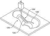
FIG. 18 is a schematic view of an embodiment of a step in the process of printing a tubular structure onto an eyelet plate; and
fig. 19 is a schematic diagram of a process for forming a tubular structure having a customized contoured path on an article, according to an embodiment.
Detailed Description
Embodiments include articles of footwear having a tubular structure for applying tension throughout one or more regions of the article of footwear, and methods for printing the tubular structure onto the article of footwear. The tubular structure may extend along an upper of the article of footwear.
This embodiment provides an article of footwear having an upper. The article also includes a tubular structure having a first end portion, a second end portion, and an intermediate portion disposed between the first end portion and the second end portion. The tubular structure forms a tunnel extending through the tubular structure from the first end to the second end. The article also includes a first tensile strand extending through at least a portion of the tunnel of the tubular structure. The intermediate portion of the tubular structure includes a tab portion extending away from the intermediate portion. The tab portion is attached to the article of footwear and anchors the tubular structure to the article of footwear.
Embodiments also provide an article of footwear having an upper and a sole structure joined at least at a bite line of the article of footwear. The article also includes a tubular structure having a first end, a second end, and an intermediate portion disposed between the first end and the second end. The tubular structure forms a tunnel extending through the tubular structure from the first end to the second end, wherein the intermediate portion of the tubular structure includes a surface having an opening extending to the tunnel. The article also includes a first tensile strand extending through the tunnel of the tubular structure. The second tensile strand has a first portion attached to an attachment area of the article of footwear. The second tensile strand also has a second portion engaged with the first tensile strand proximate the opening. The intermediate portion is disposed adjacent to a bite line of the article of footwear.
Embodiments also provide a method of making an article of footwear having an upper. The method includes the step of receiving a custom design for a tubular structure. The method also includes printing a printing material onto a surface of the upper to form a tubular structure having an aperture, wherein the tubular structure is printed with an opening extending from the surface of the tubular structure to the aperture. The method also includes printing the printed material to form a tab portion integral with the tubular structure. The method also includes inserting a tensile strand through the tunnel of the tubular structure.
Other systems, methods, features and advantages of the embodiments will be or will become apparent to one with skill in the art upon examination of the following figures and detailed description. It is intended that all such additional systems, methods, features and advantages be included within this description, be within the scope of the embodiments, and be protected by the accompanying claims.
Fig. 1 is an isometric view of an embodiment of an article of footwear 100. In an exemplary embodiment, article of footwear 100 has the form of an athletic shoe. However, in other embodiments, the arrangements discussed herein with respect to article of footwear 100 may be incorporated into various other types of footwear, including, but not limited to: basketball shoes, hiking boots, soccer shoes, football shoes, rubber-soled athletic shoes, running shoes, cross-training shoes, soccer shoes, baseball shoes, and other types of shoes. Moreover, in some embodiments, the arrangements discussed herein with respect to article of footwear 100 may be incorporated into various other types of non-athletic related footwear, including, but not limited to: slippers, sandals, high-heeled shoes and loafers (loafers).
For clarity, the following detailed description discusses features of article of footwear 100 (also referred to simply as article 100). However, it should be understood that other embodiments may incorporate corresponding articles of footwear (e.g., when article 100 is a right-foot article of footwear, other embodiments may incorporate a left-foot article of footwear), which may share some and possibly all of the features of article 100 described herein and shown in the figures.
Embodiments may be characterized by various directional adjectives and reference sections. These directions and reference portions may be helpful in describing various portions of an article of footwear. In addition, these directions and reference portions may also be used to describe sub-components of an article of footwear (e.g., directions and/or portions of a midsole structure, an outer sole structure, an upper, or any other component).
For consistency and convenience, directional adjectives are used throughout this detailed description corresponding to the illustrated embodiments. The term "longitudinal," as used throughout this detailed description and in the claims, refers to a direction that extends the length of an element (e.g., an upper or sole element). The longitudinal direction may extend along a longitudinal axis, which itself extends between the forefoot portion and the heel portion of the component. Furthermore, the term "transverse" as used throughout this detailed description and in the claims refers to a direction extending along the width of a component. The transverse direction may extend along a transverse axis, which itself extends between the medial and lateral sides of the component. Furthermore, the term "vertical" as used throughout this detailed description and in the claims refers to a direction extending along a vertical axis, which itself is generally perpendicular to both the lateral axis and the longitudinal axis. For example, where the item is lying flat on a ground surface, the vertical direction may extend upwardly from the ground surface. Additionally, the term "inner" refers to the portion of the article that is disposed closer to the interior of the article or closer to the foot when the article is worn. Likewise, the term "outer" refers to the portion of an article that is disposed further away from the interior or foot of the article. Thus, for example, the inner surface of the component is disposed closer to the interior of the article than the outer surface of the component. The detailed description utilizes these directional adjectives to describe an article and various components of an article, including an upper, a midsole structure, and/or an outsole structure.
As shown in fig. 1, footwear 100 may include an upper 102 and a sole structure 110. In some embodiments, sole structure 110 may be configured to provide traction for article 100. In addition to providing traction, sole structure 110 may attenuate ground reaction forces when compressed between the foot and the ground during walking, running, or other ambulatory activities. The configuration of sole structure 110 may vary significantly in different embodiments to include a variety of conventional or non-conventional structures. In some cases, the configuration of sole structure 110 may be configured according to one or more types of ground surfaces on which sole structure 110 may be used. Examples of ground surfaces include, but are not limited to: natural turf, synthetic turf, mud, hardwood floors, and other surfaces.
In different embodiments, upper 102 may have a variety of different configurations. In particular, upper 102 may have any design, shape, size, and/or color. For example, in an exemplary embodiment, article 100 is a basketball shoe, and accordingly upper 102 may have a high-top configuration (high-top configuration) shaped to provide high support at the ankle. However, in other embodiments, upper 102 may be configured as a low-top upper for running or other activities.
Fig. 2 illustrates an exploded perspective view of an embodiment of an article of footwear 100 including various components. Referring to fig. 1-2, article 100 may be provided with a tensioning system 130. The tensioning system 130 may also include a tubular structure 140, a first tensile strand 160, and a plurality of secondary tensile strands 180.
As used herein, the term "tubular structure" refers to any elongated structure having a length greater than a width and thickness (or diameter for circular geometries), the elongated structure also including an internal passage or lumen through its length. In this detailed description and in the claims, the term "tubular structure" is not intended to be limited to structures having circular inner and outer cross-sectional geometries. In other words, the tubular structure may have an external cross-sectional geometry that is approximately rectangular or polygonal, oval, or other geometries that are not necessarily circular or approximately circular. In the exemplary embodiment of fig. 1, tubular structure 140 may generally comprise an elongated structure that further comprises a bore 141. Tubular structure 140 may also have a cross-sectional geometry that includes a rounded portion 161 and a flat portion 163, rounded portion 161 facing outward from article 100, and flat portion 163 disposed substantially against upper 102.
The tubular structure 140 may also include a first end 142, a second end 144, and an intermediate portion 146 disposed between the first end 142 and the second end 144. The intermediate portion 146 need not extend the full length between the first and second ends 142, 144 and may generally characterize the area or section of the tubular structure 140 between the first and second ends 142, 144. The bore 141 of the tubular structure 140 may extend continuously through the entire length of the tubular structure 140 from the first end 142 to the second end 144. Of course, it is contemplated that in other embodiments, the bore 141 need not extend all the way to the first end 142 or the second end 144 of the tubular structure 140.
The tubular structure 140 may be configured to have one or more openings in a surface or sidewall of the tubular structure 140. In fig. 1-2, the tubular structure 140 includes a plurality of openings 150. For example, as shown in fig. 2, a first opening 152, which may represent a plurality of openings 150, is disposed in the outer surface 143 of the tubular structure 140. The first opening 152 may also extend to the tunnel 141. In other words, the first opening 152 extends from the outer surface 151 to the inner surface 153 (shown in fig. 1) of the tubular structure 140. It should be understood that each of the remaining openings of the plurality of openings 150 may likewise extend from the outer surface 143 to the tunnel 141. Thus, the plurality of openings 150 may provide an entry point for components (such as the tensile wires) to enter or exit the tunnel 141. Although not shown in the figures, the first end 142 and the second end 144 of the tubular structure 140 may likewise include openings that allow access to the tunnel 141.
The embodiment shown in fig. 1-2 has a common orientation for a plurality of openings 150 along the tubular structure 140. Specifically, each of plurality of openings 150 is oriented generally toward an instep of article 100. However, other opening orientations are possible, and in some embodiments, different apertures may be configured to have different orientations.
In various embodiments, one or more dimensions of the tubular structure and the tunnels and openings formed therein may vary. For example, in various embodiments, the outer diameter of the tubular structure may have any value in the range between 0.1mm and 2 cm. Likewise, the tube thickness, as characterized by the distance between the outer and inner surfaces (e.g., outer surface 151 and inner surface 153), may have any value within a range between 0.5mm and 1.8 cm. It will be appreciated that the diameter of the bore may vary depending on the tube thickness (i.e., the bore diameter is the diameter of the tubular structure minus twice the tube thickness). Further, the diameter and tube thickness of the tubular structure may be selected based on various factors including the desired tensile strand diameter, the desired flexibility of the tubular structure, the desired height of the tubular structure relative to the upper, and possibly other factors.
Furthermore, the number and arrangement of the openings may vary. For example, some embodiments may include only a single opening, while other embodiments may include between two and 50 openings. Still other embodiments may include more than 50 openings. The number of openings may be selected according to the required number of entry points to the duct and the desired flexibility of the tubular structure, as additional openings may increase the flexibility of the tubular structure immediately adjacent to the opening. It will also be appreciated that the openings may be disposed uniformly through the tubular structure, or in any discrete group or pattern.
The size of the opening may vary. For example, the circumferential dimension of the opening may characterize how much circumference the opening covers the tubular structure. Some embodiments may include openings having a circumferential dimension of only a few percent of the total circumference of the tubular structure. Still other embodiments may include openings having a circumferential dimension that is between 20% and 80% of the circumference of the tubular structure. For example, in other embodiments, the opening may be large enough such that only a narrow portion of the tubular structure connects adjacent portions of the tubular structure at the opening.
The tubular structure may be configured to have various physical properties. Exemplary physical properties of the tubular structure that may be varied include stiffness, strength, and flexibility or elasticity. In some embodiments, for example, the tubular structure may be configured to be relatively rigid with little flexibility. In the embodiment of fig. 1-2, the tubular structure 140 may be configured to have some flexibility such that one or more portions of the tubular structure 140 may undergo elastic deformation during tensioning.
Different embodiments may use different materials for the tubular structure. Exemplary materials may include, but are not limited to, various types of polymers. In embodiments where the tubular structure may be formed by a 3D printing process, the tubular structure may be made of materials including, but not limited to: thermoplastics (e.g., PLA and ABS) and thermoplastic powders, high density polyethylene, eutectic metals, rubber, molding clay, plasticine, RTV silicone, porcelain, metal clay, ceramic materials, gypsum and photopolymers, and possibly other materials known for use in 3D printing. Such materials may be referred to herein as "printable materials.
The tensioning system 130 includes a first tensile strand 160 and a plurality of secondary tensile strands 180. As used herein, the term "tensile strand" refers to any elongated (e.g., approximately two-dimensional) element capable of transmitting tension across its length. Examples of various types of tensile strands that may be used with embodiments include, but are not limited to, cords, laces, wires, cables, wires, cords, filaments, yarns, and possibly other types of strands. The tensile strands may be configured to have different strengths and different degrees of stretchability or elasticity.
The first tensile strand 160 may include a cord-like element (cord-like element) having an approximately circular cross-section. The first tensile strand 160 includes a first end portion 162, a second end portion 164, and an intermediate portion 166. Although the length of the first tensile strand 160 may vary from one embodiment to another, in an exemplary embodiment, the first tensile strand 160 may be longer than the tubular structure 140 such that the first and second end portions 162, 164 extend outwardly from the first and second ends 142, 144, respectively, of the tubular structure 140.
In some embodiments, the first tensile strand 160 may include provisions that prevent the first end portion 162 or the second end portion 164 from being pulled into the tunnel 141 of the tubular structure 140. Such elements may be referred to herein as "catching elements," although the exemplary embodiments of fig. 1-2 are not depicted as having any catching elements. The retaining element may comprise a knot formed in the tensile strand, or other element clipped or tied to the tensile strand. The catch element may generally have a cross-sectional size and/or shape that prevents the catch element from being pulled into the tubular structure. Alternatively, the stop element may press against the end of the tubular structure, allowing the other end of the tensile strand to be pulled so as to create tension across the tensile strand.
Embodiments may include provisions for facilitating attachment of a tubular structure to one or more structures of an article of footwear (also referred to as "attachment structures"). In some embodiments, the tubular structure may include a portion of the tubular portion extending away from the tubular structure, which may be the portion forming the bore of the tubular structure. In some embodiments, the tubular structure may include one or more tab portions extending away from the tubular or tunnel portion of the tubular structure.
In the embodiment shown in fig. 2, the middle portion 146 of the tubular structure 140 may include a plurality of tab portions 200. The plurality of tab portions 200 may be integral with the tubular portion 147 of the intermediate portion 146 and extend away from the tubular portion 147 of the intermediate portion 146. For example, tab portion 201 of plurality of tab portions 200 includes a first end 202 integral with tubular portion 147 and a second end 204 distal to tubular portion 147 (and spaced from tubular portion 147).
The tab portion may be configured in a variety of different shapes and/or sizes. The embodiment of fig. 2 depicts a tab portion having a generally rectangular cross-sectional shape; however, other embodiments may be configured to have any cross-sectional shape, including but not limited to a semi-circular shape, a triangular shape, a regular shape, and/or an irregular shape. In addition, one or more dimensions of the tab portion may vary. For example, the tab portion may be configured to have a length (i.e., a dimension extending perpendicular to the tubular portion) in a range between approximately 1% and 25% of the length of the tubular structure. In still other embodiments, the tab portion may have a length approximately in a range between 0.1% and 1% of the length of the tubular structure. It may be appreciated that the shape and/or size of the tab portion may be selected to achieve a predetermined surface area of an attachment structure for attaching the tab portion to an article of footwear. Further, the shape and/or size may be selected according to the type and/or location of the attachment structure.
As discussed in further detail below, the tab portion may be attached to various attachment structures on the article of footwear. Exemplary attachment structures include, but are not limited to, portions of an upper, portions of a sole structure, heel counters, toe guards, heel cups, ankle guards, support pads, mesh sheets, tongues, eyelets (or lacing stabilizers), eyelets, straps, laces, and other types of structures. In some embodiments, the bite line can be an attachment structure in that it includes adjacent portions of the upper and the sole structure.
Referring to fig. 1-2, the plurality of secondary tensile strands 180 includes four secondary tensile strands (or simply "tensile strands"). Specifically, as seen in fig. 1-2, the plurality of secondary tensile strands 180 includes a second tensile strand 182, a third tensile strand 183, a fourth tensile strand 184, and a fifth tensile strand 185. In other embodiments, the tensioning system 130 may include fewer than four secondary support wires. In still other embodiments, the tensioning system 130 can include more than four secondary tension wires.
In various embodiments, one or more characteristics of two or more tensile strands may vary. In some embodiments, the materials and/or dimensions of the first and second tensile strands may be substantially similar. However, in other embodiments, the material and/or dimensions of the first and second tensile strands may be different. For example, the exemplary embodiment depicts a first tensile strand 160 that is much longer than any of the plurality of secondary tensile strands 180. Further, the first tensile strand 160 may have a larger diameter than a second tensile strand 182, the second tensile strand 182 being a representative tensile strand of the plurality of secondary tensile strands 180. In particular, in some embodiments, each tensile strand of plurality of secondary tensile strands 180 may have a similar diameter.
In some embodiments, the first tensile strand 160 may also be made of a different material than the second tensile strand 182. For example, in some embodiments, the first tensile strand 160 may be made of nylon, while the second tensile strand 182 may be made of a high strength material such as Vectran. The use of this combination of materials may allow for somewhat more stretch and durability in the first tensile strand 160 that may be subjected to stresses in many different directions. However, in other embodiments, the first tensile strand 160 and the second tensile strand 182 may be made of similar materials that impart similar physical properties (including similar strength, stretchability, and durability).
Optionally, in some embodiments, the tensile strand may be encased in a coating, such as a PTFE coating, which allows the tensile strand to be smoothly pulled or pushed through the tunnel and/or against a surface, such as an upper, with minimal resistance. It is also contemplated that in some other embodiments, portions of the plurality of secondary tensile strands 180 may be laminated, covered, or embedded within a TPU layer or other polymer material that may help incorporate the plurality of secondary tensile strands 180 along their length into the upper.
Referring to fig. 1, in the assembled article 100, the tubular structure 140 extends along the bite line 125 on the outer surface 105 of the upper 102. Specifically, first end 142 of tubular structure 140 (see fig. 2) begins in heel portion 14 on medial side 18, extends through midfoot portion 12 and forefoot portion 10 on medial side 18, and then passes through lateral side 16 at the front of article 100. From the front on lateral side 16, tubular structure 140 extends through forefoot portion 10 and midfoot portion 12, and to heel portion 14 on lateral side 16. Second end 144 is disposed in heel portion 14.
In some embodiments, each secondary tensile strand may comprise a looped thread or element wrapped around the top or instep of upper 102. In addition, each secondary tensile strand includes a portion that engages first tensile strand 160 and provides a means of transferring tension between first tensile strand 160 and one or more other regions of article 100 (e.g., transferring tension across the instep of upper 102).
Various arrangements may be used to secure the tubular structure to the article. In embodiments including a tubular structure having a tubular portion and a tab portion extending from the tubular portion, the tubular portion and/or tab portion may be attached to one or more structures of the article. For example, in some embodiments, the tubular portion may be attached to the upper. In other embodiments, the tab portion may be attached to an upper and/or another structure of the article. In still other embodiments, the tubular portion and one or more tab portions may be attached to other structures of the upper and/or article.
As used herein, "attached" between a portion of a tubular structure and a portion of an article can include any of a variety of different attachment means. Examples of attachment means include, but are not limited to, direct bonding (i.e., bonding between compatible materials, such as bonding a fabric with a suitable polymeric material using heat and/or pressure), adhesives, and other attachment means known in the art. In some embodiments, the tubular portion and/or tab portion may be attached to an upper, sole structure, or other component during a three-dimensional printing process, where the portion is printed onto the article as a three-dimensional structure and is integrated with a portion of the article as the printed material cools and/or solidifies. Some exemplary attachment means are discussed in more detail below and shown in fig. 6-7.
Fig. 3-4 illustrate schematic perspective views of article 100, including enlarged cross-sectional views of article 100. Referring to fig. 3-4, a plurality of tab portions 200 may be attached to the article 100 at the bite line 125. For example, tab portion 210 of plurality of tab portions 200 may be disposed between sole structure 110 and upper 102 on medial side 18. Likewise, tab portion 212 of plurality of tab portions 200 may be disposed between sole structure 110 and upper 102 on lateral side 16. Similarly, the remaining plurality of tab portions 200 may be disposed between sole structure 110 and upper 102, as shown in fig. 5, which fig. 5 illustrates a top-view schematic view of article 100 with upper 102 shown in phantom.
Each tab portion may engage with a surface of upper 102 and/or sole structure 110 when attached to article 100 at bite line 125. As seen in fig. 3, tab portion 210 includes a first surface 231 that contacts outer surface 105 of upper 102 and a second surface 232 that contacts inner surface 111 of sole structure 110. Similarly, each tab portion of plurality of tab portions 200 may likewise include opposing surfaces that contact outer surface 105 of upper 102 and inner surface 111 of sole structure 110, respectively.
In some embodiments, each tab portion may be secured to both upper 102 and sole structure 110 (i.e., to outer surface 105 of upper 102 and to inner surface 111 of sole structure 110). However, in other embodiments, the tab portion may be attached to only one of upper 102 and sole structure 110. For example, in another embodiment, a first surface of the tab portion may be attached to upper 102, while an opposing second surface may not be attached to sole structure 110, although the opposing second surface may be adjacent to sole structure 110 and/or in contact with sole structure 110. In another embodiment, a first surface of the tab portion may be attached to sole structure 110, while an opposing second surface may not be attached to upper 102, although the opposing second surface may be adjacent to upper 102 and/or in contact with upper 102.
By attaching the plurality of tab portions 200 at the bite line 125 of the article 100, the plurality of tab portions 200 can anchor the tubular structure 140 in place along the bite line 125. This arrangement can help prevent the tubular structure 140 from moving away from the bite line 125. In contrast, for example, in embodiments where tubular structure 140 is secured to a side portion of upper 102, the tubular structure may change its absolute position on article 100 as upper 102 deforms (e.g., stretches or compresses) under tension applied by tensioning system 130.
Fig. 3-4 also illustrate how tension applied to first tensile strand 160 may transfer the tension to a plurality of secondary tensile strands 180 and ultimately across portions of upper 102. In a relaxed state, as shown in fig. 3, the plurality of secondary tensile strands 180 may pull portions of the first tensile strand 160 out of the plurality of openings 150 in the tubular structure 140. In fig. 4, a tensioning force 280 is applied to the end of the first tensile wire 160, resulting in a tensioned or tightened state of the tensioning system 130. This causes the first tensile strand 160 to be tensioned within the tubular structure 140. When first tensile strand 160 is tensioned, the plurality of secondary tensile strands 180 are pulled into the plurality of openings 150 (e.g., second tensile strand 182 is pulled into opening 159). Accordingly, tension is generated across the plurality of secondary tensile strands 180, which results in a tightening of upper 102. In addition, the plurality of tab portions 200 may serve to inhibit movement of the tubular structure 140 toward the instep of the upper 102, which is the direction in which the plurality of secondary tensile strands 180 will tend to pull the first tensile strand 160 and the tubular structure 140. Thus, such a configuration may thus help ensure that tension applied along first tensile strand 160 is used to tighten upper 102, rather than moving tubular structure 140 along upper 102.
In other embodiments, various other arrangements of secondary tensile strands are possible. In some embodiments, the tensile strand may extend from the tubular structure to the bite line. In other embodiments, the tensile strand may extend between two different portions of the tubular structure or between two separate tubular structures. Further, some embodiments may be configured with a combination of tensile strands extending to the bite line or across the upper to other portions of the tubular structure. In still other embodiments, one or more portions of the secondary tensile strands may be directly attached to a portion of the upper using, for example, a laminate layer to bond the tensile strands to the upper, or using various types of welding.
This embodiment enables the tab portion to be attached to the article of footwear using a variety of different methods. Fig. 6 depicts an enlarged cross-sectional view of an embodiment in which the tab portion is directly bonded to a surface of the upper. Referring to fig. 6, the tubular structure 300 includes a tubular portion 302 and a tab portion 304. Tab portion 304 may extend between an inner surface 322 of sole structure 320 and an outer surface 312 of upper 310. In the embodiment of fig. 6, surface 305 of tab portion 304 is bonded directly to outer surface 312 of upper 310. Specifically, tab portion 304 may include a material that is directly bonded with a material comprising a portion of upper 310. As an example, the tab portion 304 may include printable material printed (or otherwise deposited) onto the outer surface 312 and bonded with the outer surface 312.
In embodiments where direct bonding occurs between the tab portion and a structure, such as an upper, such direct bonding may also occur between the tubular portion and the structure (e.g., the upper). For example, as seen in the embodiment of fig. 6, portion 303 of tubular portion 302 may also be bonded directly to outer surface 312 of upper 310. Thus, it may be appreciated that, in some embodiments, the tab portion may provide additional surface area for attaching the tubular structure to an upper or other structure of the article of footwear, and may not be the only means for attachment of the tubular structure. Alternatively, in some other embodiments, only the tab portion may be directly bonded to the upper or other structure, and the tubular portion of the tubular structure may be separate from the upper.
Fig. 7 depicts an enlarged cross-sectional view of an embodiment in which an adhesive layer is used to attach the tab portion to the sole structure. Referring to fig. 7, the tubular structure 400 includes a tubular portion 402 and a tab portion 404. Tab portion 404 may extend between an interior surface 422 of sole structure 420 and an exterior surface 412 of upper 410. In the embodiment of fig. 7, surface 405 of tab portion 404 is attached to surface 444 of adhesive layer 440. Additionally, surface 442 of the adhesive layer is attached to interior surface 422 of sole structure 420. In other words, the adhesive layer is used to attach the tab portion 404 and the sole structure 420. Further, unlike the embodiment shown in fig. 6, in the embodiment of fig. 7, the tubular portion 402 is shown as being directly separate from (not bonded to) the outer surface 412 of the upper 410. Of course, in other embodiments, the tab portion may be attached to the sole structure using an adhesive layer, and the tubular portion may be bonded directly to the outer surface of the upper.
Embodiments may include provisions for attaching a tubular structure to one or more structures on an article of footwear. Such structures may include heel counters, toe guards, eyelets, and possibly other structures. In the embodiment shown in fig. 8-9, article of footwear 500 (or simply article 500) includes an upper 502 and a sole structure 510. Article 500 also includes an external heel counter 520 in heel region 514.
To secure the tubular structure 530 in the heel region 514 of the article 500, the tubular structure 530 includes a plurality of tab portions 538 that are directly attached to the external heel counter 520. In some embodiments, the plurality of tab portions 538 may be attached directly to the interior surface 521 (see fig. 9) of the external heel counter 520. In this case, a plurality of tab portions 538 may be inserted between the outer heel counter 520 and the outer surface of the upper 502. In other embodiments, of course, one or more tab portions may be attached to the outer surface of the external heel counter 520.
Attaching the tubular structure (via the tab portion) to the heel counter may help anchor some portions of the tubular structure in place, thereby minimizing movement of the tubular structure in the heel portion.
In another embodiment depicted in fig. 10, article 600 includes an upper 602, a sole structure 610, and a tubular structure 630. The tubular structure 630 may include a plurality of tab portions 640 that engage the eyelet plate 650. Specifically, the first tubular portion 632 of the tubular structure 630 may be disposed adjacent an edge of the eyelet plate 650. A plurality of tab portions 640 may extend from the first tubular portion 632 and engage an eyestay (eyestay) 650. Second tubular portion 634 disposed in forefoot portion 603 of article 600 may be disposed adjacent bite line 615. In some cases, additional tab portions (not shown) may be engaged with upper 602 and/or sole structure 610 at bite line 615.
In some embodiments, the plurality of tab portions 640 may be directly attached to the eyelet plate 650. In the embodiment of fig. 10, a plurality of tab portions 640 may be attached to an interior surface of the eyelet flap 650, the interior surface of the eyelet flap 650 being in contact with the exterior surface 604 of the upper 602. In addition, a plurality of tab portions 640 may be disposed between the exterior surface 604 of the upper 602 and the interior surface of the eyelet flap 650. Alternatively, in another embodiment, the plurality of tab portions 640 may be attached to an outer surface 651 of the eyelet plate 650, the outer surface 651 being disposed opposite the inner surface.
As previously discussed, the tab portion may be attached to a structure (e.g., a heel counter or an eyelet plate) using any known method, including direct bonding, using adhesives, and possibly other attachment methods. The attachment method may be selected based on various factors, including the material composition of the tab portion and attachment structure, as well as manufacturing considerations (e.g., manufacturing costs).
Embodiments may include provisions for receiving a plurality of tensile strands within a bore of a tubular structure. In some embodiments, the bore of the tubular structure may be configured to receive at least two tensile wires. In still other embodiments, the tunnel of the tubular structure may be configured to receive three or more tensile strands.
Fig. 11 illustrates an embodiment of an article of footwear 700 (or simply article 700) having a tensioning system 730 that includes a plurality of tensile strands within a tubular structure 740. To control the tension at first set of secondary tensile strands 750 in heel portion 714, first tensile strand 732 may extend through tubular structure 740 and engage first set of secondary tensile strands 750 by way of first plurality of openings 742. Here, first tensile strand 732 may enter/exit tubular structure 740 through an opening at end 741 of tubular structure 740. By applying tension along first tensile strand 732, tension may be applied along first set of secondary tensile strands 750 and thus through heel portion 714.
Additionally, in the embodiment of fig. 11, a second set of second tensile strands 734 may be inserted into openings 745 on the tubular structure 740. Here, the opening 745 may be disposed in a middle portion of the tubular structure 740, or in other words, between the ends 741 of the tubular structure 740. The second tensile strand 734 may thus enter/exit the tubular structure 740 at the opening 745 on one side of the article 700 and a similar intermediate opening (and/or opening at the end) of the tubular structure 740 on the opposite side (not shown) of the article 700. To control the tension at the second set of secondary support wires 752, the second support wire 734 may extend through the tubular structure 740 and engage the second set of secondary support wires 752 via the second plurality of openings 744. By applying tension along second tensile strand 734, tension may be applied along second set of secondary tensile strands 752, and thus through forefoot portion 703.
Thus, the exemplary embodiment of fig. 11 depicts a tensioning system that may be used to independently apply tension to two different portions or regions of an article.
In various embodiments, the spacing between the openings may be regular and/or irregular. For example, the spacing between adjacent openings of the first plurality of openings 742 in fig. 11 can be approximately constant. Specifically, two adjacent openings may be spaced apart a distance 760 along the tubular structure 740. In contrast, openings 770 of first plurality of openings 742 may be spaced apart from openings 745 by a distance 762, wherein distance 762 is greater than distance 760. In addition, second plurality of openings 744 in forefoot portion 703 includes openings 771 and adjacent openings 772, with openings 771 being spaced apart from adjacent openings 772 by distance 764 and openings 772 being spaced apart from adjacent openings 773 by distance 766 which is less than distance 764.
It will be appreciated that the spacing between adjacent openings on the tubular structure may be varied to accommodate the desired tensioning arrangement. Moreover, varying the number and spacing between the holes can affect the degree to which the tubular structure deforms when tension is applied along the tensile strand.
Embodiments may include an arrangement for making an article having a tubular structure including a tab portion. In some embodiments, the tubular structure may be formed and attached to the article using an additive manufacturing process also known as three-dimensional printing (or simply "printing" hereinafter).
Referring to fig. 12, a manufacturing system 960 includes an additive manufacturing apparatus 980. The term "additive manufacturing" (also referred to as "three-dimensional printing") refers to any apparatus and technique for making three-dimensional objects by an additive process in which layers of material are deposited continuously under computer control. Exemplary additive manufacturing techniques that may be used include, but are not limited to: extrusion methods such as Fused Deposition Modeling (FDM), electron beam free formation fabrication (EBF), Direct Metal Laser Sintering (DMLS), Electron Beam Melting (EBM), Selective Laser Melting (SLM), Selective Heat Sintering (SHS), Selective Laser Sintering (SLS), gypsum-based 3D printing (plate-based 3D printing), layered body fabrication (LOM), Stereolithography (SLA), and Digital Light Processing (DLP). In one embodiment, the additive manufacturing apparatus 980 may be a fused deposition modeling printer configured to print thermoplastic materials (e.g., Acrylonitrile Butadiene Styrene (ABS) or polylactic acid (PLA)).
An example of a printing Apparatus using fuse manufacturing (FFF) is disclosed in U.S. Pat. No. 5,121,329 filed by Crump at 30/10 1989 and entitled "Apparatus and Method for Creating Three-Dimensional Objects", which is hereinafter referred to as the "3D object" application. Embodiments of the present disclosure may utilize any of the systems, components, devices, and methods disclosed in the 3D object application.
The additive manufacturing apparatus 980 may be used to manufacture one or more components used in forming an article of footwear. For example, the additive manufacturing apparatus 980 may be used to form a tubular structure having tab portions on an upper.
The additive manufacturing apparatus 980 may include an apparatus housing 981, an actuation assembly 982 (see fig. 12), and an extrusion head 984 (see fig. 13). The additive manufacturing apparatus 980 may also include a platform 986. In some cases, extrusion head 984 may be translated in the z-axis (i.e., vertical axis) via actuation assembly 982, while platform 986 of additive manufacturing apparatus 980 may be moved in the x-direction and the y-direction (i.e., horizontal axis). In other cases, extrusion head 984 may have full three-dimensional motion (e.g., x-y-z motion) above a fixed platform.
Embodiments may include settings for controlling the additive manufacturing equipment 980 and processing information related to the customization process. These settings can include the computing system 990 and the network. In general, the term "computing system" refers to a computing resource of a single computer, a portion of a computing resource of a single computer, and/or two or more computers in communication with each other. Any of these resources may be operated by one or more human users. In some embodiments, computing system 990 may include one or more servers. In some cases, a separate server (not shown) may be primarily responsible for controlling and/or communicating with the devices of manufacturing system 960, while a separate computer (e.g., desktop, laptop, or tablet) may facilitate interaction with a user or operator. The computing system 990 may also include one or more storage devices, including, but not limited to, magnetic, optical, magneto-optical storage devices, and/or memory including volatile memory and non-volatile memory.
The computing system 990 may include a viewing interface 996 (e.g., a monitor or screen), an input device 997 (e.g., a keyboard and/or mouse), and software for designing a computer-aided design ("CAD") representation of a three-dimensional model. In at least some embodiments, the CAD representation can provide a representation of the article of footwear as well as a representation of an element of the tensioning system (such as a tubular structure).
In some embodiments, computing system 990 may be in direct communication with one or more devices or systems of manufacturing system 960 via network 999. The network may include any wired or wireless arrangement that facilitates the exchange of information between the computing system 990 and the devices of the manufacturing system 960. In some embodiments, the network may also include various components, such as network interface controllers, repeaters, hubs, bridges, switches, routers, modems, and firewalls. In some cases, the network may be a wireless network that facilitates wireless communication between two or more systems, devices, and/or components of manufacturing system 960. Examples of wireless networks include, but are not limited to: wireless personal area networks (including, for example, bluetooth), wireless local area networks (including networks utilizing the IEEE 802.11WLAN standard), wireless mesh networks, mobile device networks, and other kinds of wireless networks. In other cases, the network may be a wired network including a network whose signals are facilitated by twisted pair (twister pair wires), coaxial cable, and optical fiber. In still other cases, a combination of wired and wireless networks and/or connections may be used.
Fig. 13-15 illustrate one exemplary process for forming a tubular structure having a tubular portion such that the tubular portion is directly attached to an upper of an article of footwear. Referring first to fig. 13, a material component 1000 configured to be formed into a three-dimensional upper 1202 (see fig. 16) may be placed on a platform 986 in preparation for printing. The extrusion head 984 may begin depositing (i.e., printing) printable material onto the material component 1000. As previously discussed with reference to the embodiment of fig. 1, the term "printable material" is intended to encompass any material that may be printed, jetted, ejected, or otherwise deposited during an additive manufacturing process. Such materials may include, but are not limited to, thermoplastics (e.g., PLA and ABS) and thermoplastic powders, high density polyethylene, eutectic metals, rubber, molding clay, plasticine, RTV silicone, porcelain, metal clay, ceramic materials, gypsum and photopolymers, and possibly other materials known for use in 3D printing.
As shown in fig. 13, during printing, a tubular structure is formed by printing a portion of the tunnel portion 1102 and a tab portion 1104 extending from the tunnel portion 1102. In this exemplary embodiment, the deposited printable material may be directly bonded to the material component 1000 (i.e., the printable material and the material component 1000 may be bond compatible) such that the resulting tubular structure 1100 is fixedly attached to the material component 1000 (which is shaped as an upper in subsequent steps of the process).
Next, as shown in FIG. 14, tensile strand 1110 may be inserted into a partial tunnel of lower portion 1108 after lower portion 1108 of tubular structure 1100 has been formed. Finally, as seen in fig. 15, an extrusion head 984 may be used to print the remaining upper portion 1109 of the tubular structure 1100, thereby enclosing most of the tensile strand 1110. In this exemplary embodiment, tensile strand 1110 may be configured such that no bonding occurs between tensile strand 1110 and any printable material, thereby allowing tensile strand 1110 to translate through the resulting tunnels formed within tubular structure 1100.
Finally, as shown in fig. 16, in some embodiments of the method, the resulting material element 1000 is formed into an upper 1202. Upper 1202 may then be combined with sole structure 1204 to form article of footwear 1210. In some embodiments, tab portions 1104 may be arranged such that they are located at bite line 1215 and are disposed between upper 1202 and sole structure 1204.
It should be understood that the processes illustrated in fig. 13-15 are intended to be exemplary only. In other embodiments, similar methods may be used to form a tubular structure that is attached at one or more tab portions to a heel counter, an eyelet plate, and any other structure on an article. As an example, fig. 17 illustrates an embodiment in which a section of a tubular structure 1250 is printed onto a heel counter 1252 of an article 1254. Specifically, tab portions 1256 are printed onto the outer surface of heel counter 1252 to directly attach tubular structure 1250 and heel counter 1252. Of course, in other embodiments, the tab portions may be printed onto the interior surface of the heel counter, for example, prior to assembling the heel and shoe with the upper. As another example, fig. 18 illustrates an embodiment in which a section of a tubular structure 1260 is printed onto an eyelet sheet 1262 of an article 1264. Specifically, tab portions 1266 are printed onto the outer surface of the eyelet plate 1262 to directly attach the tubular structure 1260 and the eyelet plate 1262. Of course, in other embodiments, the tab portions may be printed onto the inner surface of the eyelet plate, for example, prior to assembling the eyelet plate with the upper.
Alternatively, in other embodiments, the entire tubular structure printed may be printed, and the tensile strand may then be inserted into the resulting fully formed tunnel. Some embodiments may include provisions for customizing the path of the tubular structure on the article. One such method is depicted in fig. 19.
Fig. 19 illustrates an exemplary process for manufacturing an article with a tensioning system, according to an embodiment. It will be appreciated that in some embodiments one or more steps may be optional, while in other embodiments the process may include additional steps. Thus, the method may not be limited to the specific steps or order of steps discussed herein. It will also be appreciated that one or more steps may be performed by one or more of the following: a manufacturer, a retail worker, a customer, and/or a third party.
In a first step 1350, custom foot geometry information may be received. Such customized foot information may include information collected from the imaging device and/or the pressure sensing device, which may provide information about the geometry of the foot and/or the pressure distribution along the bottom of the foot. Next, during step 1352, a customized contoured path for the tubular structure may be determined, for example, using software that automatically determines a customized contoured path from the customized foot information, or using software that allows a user to manually design a contoured path using the customized foot information. Next, during step 1354, a printing material may be disposed on the upper to form a tubular structure having a customized, contoured path. Finally, during step 1356, an article of footwear may be manufactured using an upper having a tubular structure disposed in the customized path.
Additive manufacturing processes can be used to form structures on planar receiving surfaces as well as on contoured or non-planar surfaces. For example, some embodiments depicted in the figures may illustrate methods by which material is printed onto a planar surface of an article (e.g., a material portion of an upper having a planar or unassembled configuration). In this case, printing the material onto the surface may be accomplished by depositing the material in a thin layer that is also flat. Thus, the print head or nozzle may be moved in one or more horizontal directions to apply the nth layer of material, and then moved in a vertical direction to begin forming the N +1 layers. However, it should be understood that in other embodiments, the material may be printed onto a contoured or non-flat surface. For example, the material may be printed onto a three-dimensional last, where the surface of the last is not flat. In this case, the printed layer applied to the surface may also be profiled. To implement such a printing method, the print head or nozzle may be configured to move along the contoured surface as well as tilt, rotate, or otherwise move such that the print head or nozzle is always aligned substantially orthogonally to the surface to which the printing material is applied. In some cases, the print head may be mounted to a robotic arm, such as an articulated robotic arm having six degrees of freedom. Alternatively, in still other embodiments, an object having a contoured surface may be reoriented under the nozzle such that a contoured layer of printing material may be applied to the object. For example, embodiments may utilize any of the systems, features, components, and/or methods disclosed in U.S. patent publication No. 2013/0015596 entitled "rolling fault," published by Mozeika et al at 2013, month 1, 17 (and filed at 2012, month 6, 22 as U.S. application No. 13/530,664). Embodiments may also utilize any of the systems, features, components and/or methods disclosed in U.S. patent No. 8,123,350 entitled "Computerized apparatus and method for applying graphics to surfaces," issued on 28/2 2012 by Cannell et al. Thus, it may be appreciated that the present embodiments are not limited to printing processes for printing to flat surfaces and may be used in conjunction with printing systems that may print to any kind of surface having any kind of geometry.
The printing structure of this embodiment may provide enhanced support. In some cases, one or more printed structures may be attached to an underlying component, such as a fabric layer of an upper or other article, and may be used to enhance support over a portion of the component. This may occur where the printed structure is more rigid than the underlying material (e.g., fabric, leather, etc.). In some cases, a printed structure, such as a tubular structure, may extend over an entire portion of the article to form an external support system, such as an exoskeleton, which helps provide increased support through those portions.
Embodiments also provide a full fit system that provides a tailored and pressure-free fit for an item. This is accomplished by manipulating the articulating tunnel structure around the bony prominences of the foot. As the tensile strand extending through the tunnel structure is pulled under tension (e.g., by a lace or another tensile element), the tunnel geometry and article substrate (e.g., a fabric layer) contract around the predetermined area of the foot.
While various embodiments have been described, the description is intended to be exemplary, rather than limiting and it will be apparent to those of ordinary skill in the art that many more embodiments and implementations are possible that are within the scope of the embodiments. Any feature of any embodiment may be used in combination with or in place of any other feature or element in any other embodiment, unless specifically limited. Accordingly, the embodiments are not to be restricted except in light of the attached claims and their equivalents. Also, various modifications and changes may be made within the scope of the appended claims.
Claims (19)
1. An article of footwear comprising:
a shoe upper;
a tubular structure attached to the upper and extending along a surface of the upper, the tubular structure including a first end, a second end, and an intermediate portion disposed between the first end and the second end;
a bore extending through the tubular structure from the first end to the second end;
a first tensile strand extending through at least a portion of the tunnel of the tubular structure;
a plurality of openings in a sidewall of the middle portion of the tubular structure; and
a plurality of attachment structures extending away from the sidewall of the middle portion of the tubular structure.
2. The article of footwear of claim 1, further comprising a sole structure,
wherein an entire length of the tubular structure is positioned along a perimeter of the article of footwear at a first area where the upper is joined to a sole structure.
3. The article of footwear of claim 1, further comprising a sole structure,
wherein a first portion of a length of the tubular structure is positioned along a perimeter of the article of footwear at a first area where the upper is joined to a sole structure, and a second portion of the length of the tubular structure is positioned on the upper at a second area that is spaced apart from the first area where the upper is joined to a sole structure.
4. The article of footwear of claim 3, wherein the second region includes a heel counter.
5. The article of footwear of claim 3, wherein the second region includes a toe guard.
6. The article of footwear of claim 3, wherein the second region includes an eyelet plate.
7. The article of footwear of claim 1, wherein the plurality of attachment structures are integrally formed with the tubular structure.
8. The article of footwear of claim 1, wherein the plurality of attachment structures include tab portions.
9. The article of footwear of claim 1, further comprising a second tensile strand engaged with the first tensile strand through at least one of the plurality of openings in the sidewall of the intermediate portion.
10. The article of footwear of claim 9, wherein at least a portion of the first tensile strand, when engaged with the second tensile strand, extends through a respective one of the plurality of openings in the sidewall and an exterior of the tunnel.
11. The article of footwear of claim 9, wherein at least a portion of the second tensile strand, when engaged with the first tensile strand, extends through a respective one of the plurality of openings in the sidewall into the tunnel.
12. An article of footwear comprising:
an upper and a sole structure joined at least at a bite line of the article of footwear;
a tubular structure comprising a first end, a second end, and an intermediate portion disposed between the first end and the second end;
a bore extending through the tubular structure from the first end to the second end;
a plurality of openings formed in a sidewall of the tubular structure; and
a plurality of attachment structures extending away from the sidewall of the middle portion of the tubular structure,
wherein at least some of the plurality of openings are oriented toward an instep of the article of footwear.
13. The article of footwear of claim 12, further comprising
A first tensile strand extending through at least a portion of the tunnel of the tubular structure; and
a secondary tensile strand extending across an exterior surface of the upper and having a first portion engaged with the first tensile strand proximate at least one of the plurality of openings.
14. The article of footwear of claim 13, wherein the secondary tensile strand extends from the first tensile strand across the instep of the article of footwear.
15. An article of footwear comprising:
an upper and a sole structure joined at least at a bite line of the article of footwear;
a tubular structure comprising a first end, a second end, and an intermediate portion disposed between the first end and the second end;
a bore extending through the tubular structure from the first end to the second end;
a plurality of openings formed in a sidewall of the tubular structure;
a first tensile strand extending through the tunnel of the tubular structure;
a secondary tensile strand extending across an exterior surface of the upper and having a first portion engaged with the first tensile strand proximate at least one of the plurality of openings; and
a plurality of attachment structures extending away from the sidewall of the middle portion of the tubular structure,
wherein at least a portion of the tubular structure extends along the bite line, and
wherein the secondary tensile strand is joined to the first tensile strand by extending around the first tensile strand, thereby forming a loop.
16. The article of footwear according to claim 15, wherein the first tensile strand extends out of a respective one of the plurality of openings and engages the secondary tensile strand outside the tunnel.
17. The article of footwear of claim 15, wherein the secondary tensile strand extends into a respective one of the plurality of openings and engages the first tensile strand within the tunnel.
18. The article of footwear of claim 15, wherein a spacing between adjacent openings of the plurality of openings is regular.
19. The article of footwear of claim 15, wherein a spacing between adjacent openings of the plurality of openings is irregular.
Applications Claiming Priority (12)
| Application Number | Priority Date | Filing Date | Title |
|---|---|---|---|
| US201562263923P | 2015-12-07 | 2015-12-07 | |
| US201562263891P | 2015-12-07 | 2015-12-07 | |
| US201562263916P | 2015-12-07 | 2015-12-07 | |
| US201562263898P | 2015-12-07 | 2015-12-07 | |
| US201562263834P | 2015-12-07 | 2015-12-07 | |
| US62/263,834 | 2015-12-07 | ||
| US62/263,891 | 2015-12-07 | ||
| US62/263,916 | 2015-12-07 | ||
| US62/263,923 | 2015-12-07 | ||
| US62/263,898 | 2015-12-07 | ||
| CN201680071714.9A CN108366641B (en) | 2015-12-07 | 2016-12-06 | Article of footwear having tubular structure with tabbed portion |
| PCT/US2016/065187 WO2017100207A2 (en) | 2015-12-07 | 2016-12-06 | Article of footwear with tubular structures having tab portions |
Related Parent Applications (1)
| Application Number | Title | Priority Date | Filing Date |
|---|---|---|---|
| CN201680071714.9A Division CN108366641B (en) | 2015-12-07 | 2016-12-06 | Article of footwear having tubular structure with tabbed portion |
Publications (2)
| Publication Number | Publication Date |
|---|---|
| CN112385933A CN112385933A (en) | 2021-02-23 |
| CN112385933B true CN112385933B (en) | 2022-03-29 |
Family
ID=57570658
Family Applications (10)
| Application Number | Title | Priority Date | Filing Date |
|---|---|---|---|
| CN201680071212.6A Active CN108289525B (en) | 2015-12-07 | 2016-12-06 | Segmented tunnels on items |
| CN202011277183.3A Active CN112385933B (en) | 2015-12-07 | 2016-12-06 | Article of footwear having a tubular structure with tab portions |
| CN202110366576.XA Pending CN113080569A (en) | 2015-12-07 | 2016-12-06 | Segmented tunnel in article |
| CN202110063296.1A Active CN112890373B (en) | 2015-12-07 | 2016-12-06 | 3D Printing Using Tethered Components |
| CN202110523796.9A Active CN113180333B (en) | 2015-12-07 | 2016-12-06 | Article of footwear with tubular structure |
| CN201680071845.7A Active CN108366643B (en) | 2015-12-07 | 2016-12-06 | Articles of footwear with tubular structures |
| CN202111446617.2A Active CN114145535B (en) | 2015-12-07 | 2016-12-06 | Article of footwear having a tubular structure with tab portions |
| CN201680071448.XA Active CN108367496B (en) | 2015-12-07 | 2016-12-06 | Three-dimensional printing with binding elements |
| CN201680071839.1A Active CN108366642B (en) | 2015-12-07 | 2016-12-06 | Pore spring structure |
| CN201680071714.9A Active CN108366641B (en) | 2015-12-07 | 2016-12-06 | Article of footwear having tubular structure with tabbed portion |
Family Applications Before (1)
| Application Number | Title | Priority Date | Filing Date |
|---|---|---|---|
| CN201680071212.6A Active CN108289525B (en) | 2015-12-07 | 2016-12-06 | Segmented tunnels on items |
Family Applications After (8)
| Application Number | Title | Priority Date | Filing Date |
|---|---|---|---|
| CN202110366576.XA Pending CN113080569A (en) | 2015-12-07 | 2016-12-06 | Segmented tunnel in article |
| CN202110063296.1A Active CN112890373B (en) | 2015-12-07 | 2016-12-06 | 3D Printing Using Tethered Components |
| CN202110523796.9A Active CN113180333B (en) | 2015-12-07 | 2016-12-06 | Article of footwear with tubular structure |
| CN201680071845.7A Active CN108366643B (en) | 2015-12-07 | 2016-12-06 | Articles of footwear with tubular structures |
| CN202111446617.2A Active CN114145535B (en) | 2015-12-07 | 2016-12-06 | Article of footwear having a tubular structure with tab portions |
| CN201680071448.XA Active CN108367496B (en) | 2015-12-07 | 2016-12-06 | Three-dimensional printing with binding elements |
| CN201680071839.1A Active CN108366642B (en) | 2015-12-07 | 2016-12-06 | Pore spring structure |
| CN201680071714.9A Active CN108366641B (en) | 2015-12-07 | 2016-12-06 | Article of footwear having tubular structure with tabbed portion |
Country Status (4)
| Country | Link |
|---|---|
| US (12) | US10065369B2 (en) |
| EP (10) | EP3386332B1 (en) |
| CN (10) | CN108289525B (en) |
| WO (5) | WO2017100207A2 (en) |
Cited By (1)
| Publication number | Priority date | Publication date | Assignee | Title |
|---|---|---|---|---|
| CN114145535B (en) * | 2015-12-07 | 2025-01-14 | 耐克创新有限合伙公司 | Article of footwear having a tubular structure with tab portions |
Families Citing this family (40)
| Publication number | Priority date | Publication date | Assignee | Title |
|---|---|---|---|---|
| US10945488B2 (en) | 2013-08-09 | 2021-03-16 | Reebok International Limited | Article of footwear with extruded components |
| US9676159B2 (en) * | 2014-05-09 | 2017-06-13 | Nike, Inc. | Method for forming three-dimensional structures with different material portions |
| US9925440B2 (en) | 2014-05-13 | 2018-03-27 | Bauer Hockey, Llc | Sporting goods including microlattice structures |
| US9756899B2 (en) * | 2015-02-20 | 2017-09-12 | Nike, Inc. | Article of footwear having an upper with connectors for attaching to a sole structure |
| EP3257985A1 (en) | 2016-06-06 | 2017-12-20 | Fuerst Group, Inc. | System and method for automatic production of a cord structure |
| EP3585620B1 (en) | 2017-02-27 | 2024-05-15 | Kornit Digital Technologies Ltd. | 3d printing devices including mixing nozzles |
| US11904614B2 (en) | 2017-02-27 | 2024-02-20 | Kornit Digital Technologies Ltd. | Multi-input print heads for three-dimensionally printing and associated systems and methods |
| US11701813B2 (en) * | 2017-02-27 | 2023-07-18 | Kornit Digital Technologies Ltd. | Methods for three-dimensionally printing and associated multi-input print heads and systems |
| CN110691529B (en) * | 2017-06-27 | 2022-05-27 | 彪马欧洲股份公司 | Shoe, in particular sports shoe |
| US10485302B2 (en) * | 2017-07-07 | 2019-11-26 | Reebok International Limited | Method of making an upper |
| US20190015923A1 (en) * | 2017-07-11 | 2019-01-17 | United Technologies Corporation | Additively manufactured article including electrically removable supports |
| US10711380B2 (en) | 2017-07-13 | 2020-07-14 | Under Armour, Inc. | Article with embroidered tape segments |
| TWI773449B (en) * | 2017-10-24 | 2022-08-01 | 荷蘭商耐克創新有限合夥公司 | Frame for use in manufacturing |
| TWI751023B (en) | 2017-10-24 | 2021-12-21 | 荷蘭商耐克創新有限合夥公司 | Method of manufacturing a variety of products |
| US10583605B2 (en) * | 2018-04-19 | 2020-03-10 | The Boeing Company | Drop draw/extrude (DD/E) printing method |
| CN112469551B (en) * | 2018-06-04 | 2023-05-02 | 孔塞伊科技公司 | Method for producing a component made of composite material |
| US10619280B2 (en) | 2018-07-03 | 2020-04-14 | Under Armour, Inc. | Method of making article with ribbon structure and embroidered edges |
| US10786043B2 (en) | 2018-07-03 | 2020-09-29 | Under Armour, Inc. | Article with thermally bonded ribbon structure and method of making |
| US10736381B2 (en) | 2018-07-03 | 2020-08-11 | Under Armour, Inc. | Article with directional tensioning |
| US10736380B2 (en) | 2018-07-03 | 2020-08-11 | Under Armour, Inc. | Article with ribbon structure and embroidered edges |
| US10758007B2 (en) | 2018-07-03 | 2020-09-01 | Under Armour, Inc. | Article with thermally bonded ribbon structure and method of making |
| US10716362B2 (en) | 2018-07-03 | 2020-07-21 | Under Armour, Inc. | Article with ribbon structure having nodes and links |
| WO2020047450A1 (en) * | 2018-08-31 | 2020-03-05 | Nike Innovate C.V. | Autolacing footwear having a notched spool |
| US10993497B2 (en) * | 2018-11-15 | 2021-05-04 | Under Armour, Inc. | Article with ribbon loops for string lasting |
| CN110171201A (en) * | 2019-05-08 | 2019-08-27 | 珠海许继电气有限公司 | A kind of method and device of UV color printing production function indication panel |
| WO2020232550A1 (en) | 2019-05-21 | 2020-11-26 | Bauer Hockey Ltd. | Helmets comprising additively-manufactured components |
| CN112515291B (en) * | 2019-09-19 | 2025-07-04 | 苏州星诺奇科技股份有限公司 | Wearable products |
| IT201900025051A1 (en) * | 2019-12-20 | 2021-06-20 | Geox Spa | Light device and sole structure comprising said light device |
| CN111319366A (en) * | 2020-04-02 | 2020-06-23 | 深圳诚拓数码设备有限公司 | Printing device and printing system |
| WO2022006656A1 (en) * | 2020-07-07 | 2022-01-13 | Cormier Simonne C | Breast prosthetic device, fastening system, and uses thereof |
| IL300228B2 (en) * | 2020-07-27 | 2024-09-01 | Stratasys Ltd | Method and system for 3D printing on fabric |
| IT202000021952A1 (en) * | 2020-09-17 | 2022-03-17 | Terzopiano S R L | 3D PRINTING METHOD DIRECT ON FABRIC AND RELATED FABRIC WITH 3D PRINTING PORTION |
| US20240058142A1 (en) | 2020-12-14 | 2024-02-22 | Ntt Research, Inc. | 3d printed devices and method of use |
| US12484665B2 (en) * | 2020-12-23 | 2025-12-02 | Asics Corporation | Upper and shoe including the same |
| CN112754108B (en) * | 2021-01-12 | 2022-02-18 | 浙江纺织服装职业技术学院 | Automatic shoelace threading and guiding device |
| CA3113195A1 (en) * | 2021-03-24 | 2022-09-24 | David Lundquist | Shoelace locking apparatus |
| US12228188B2 (en) * | 2021-05-13 | 2025-02-18 | Moffitt, LLC | Methods and apparatus for a 3D-printed spring |
| US20240197036A1 (en) * | 2022-12-15 | 2024-06-20 | Nike, Inc. | Sole structure for a deconstructable footwear article |
| JP2024148754A (en) * | 2023-04-06 | 2024-10-18 | 株式会社アシックス | Shoes |
| CN117380957A (en) * | 2023-10-27 | 2024-01-12 | 成都先进金属材料产业技术研究院股份有限公司 | A 3D printed titanium alloy spring assembly and its preparation method and application |
Citations (4)
| Publication number | Priority date | Publication date | Assignee | Title |
|---|---|---|---|---|
| WO2008007403A1 (en) * | 2006-07-12 | 2008-01-17 | David Paolo Spinelli | Shoe with detachable sole and vamp |
| CN103813731A (en) * | 2011-07-18 | 2014-05-21 | 耐克国际有限公司 | Article of footwear having an upper with cord elements |
| CN104080362A (en) * | 2012-02-04 | 2014-10-01 | 彪马欧洲公司 | Shoe, in particular sports shoe |
| CN204763616U (en) * | 2015-07-16 | 2015-11-18 | 台湾百和工业股份有限公司 | Three-dimensional cloth surface pull ring structure and portable products with three-dimensional cloth surface pull ring structure |
Family Cites Families (107)
| Publication number | Priority date | Publication date | Assignee | Title |
|---|---|---|---|---|
| GB601440A (en) | 1946-05-24 | 1948-05-05 | William Lennart Grut | Improvements in or relating to toys and the like |
| US1862047A (en) * | 1930-07-08 | 1932-06-07 | Robert L Boulet | Shoe fastening device |
| US2112613A (en) * | 1936-04-04 | 1938-03-29 | Sol J Waxelbaum | Shoe |
| US2143556A (en) * | 1937-11-17 | 1939-01-10 | Hodaly Emerick | Soft shoe |
| US4870761A (en) * | 1988-03-09 | 1989-10-03 | Tracy Richard J | Shoe construction and closure components thereof |
| ATE93693T1 (en) * | 1989-06-03 | 1993-09-15 | Dassler Puma Sportschuh | CLOSING DEVICE SHOE WITH SENSITIVE CUFF MATERIAL. |
| US5121329A (en) | 1989-10-30 | 1992-06-09 | Stratasys, Inc. | Apparatus and method for creating three-dimensional objects |
| IT225832Y1 (en) * | 1991-06-10 | 1997-01-24 | Arkos Srl | FOOT LOCKING DEVICE PARTICULARLY FOR T REKKING SHOES |
| US5203944A (en) | 1991-10-10 | 1993-04-20 | Prinz Fritz B | Method for fabrication of three-dimensional articles by thermal spray deposition using masks as support structures |
| FR2692115B1 (en) | 1992-06-10 | 1995-06-23 | Mainguene Patrick | FOOTWEAR WITH A FOOT HOLDING DEVICE. |
| US5510066A (en) | 1992-08-14 | 1996-04-23 | Guild Associates, Inc. | Method for free-formation of a free-standing, three-dimensional body |
| US5362427A (en) | 1993-05-10 | 1994-11-08 | Mitchell Jr Porter H | Method and apparatus for manufacturing an article using a support structure for supporting an article during manufacture therefor |
| DE9307480U1 (en) | 1993-05-28 | 1994-10-06 | Puma Ag Rudolf Dassler Sport, 91074 Herzogenaurach | Shoe with a central twist lock |
| US5371957A (en) * | 1993-12-14 | 1994-12-13 | Adidas America, Inc. | Athletic shoe |
| CA2183149A1 (en) * | 1994-02-28 | 1995-08-31 | Adam H. Oreck | Shoe having lace tubes |
| US5535531A (en) | 1994-04-28 | 1996-07-16 | Karabed; Razmik | Shoelace rapid tightening apparatus |
| US5755044A (en) * | 1996-01-04 | 1998-05-26 | Veylupek; Robert J. | Shoe lacing system |
| US5682654A (en) | 1996-04-18 | 1997-11-04 | Fila U.S.A., Inc. | Closure element |
| US6082867A (en) | 1996-11-29 | 2000-07-04 | Chien; Tseng-Lu | Lighting arrangements including a three-dimensional electro-luminscent element |
| FR2757026B1 (en) * | 1996-12-17 | 1999-02-26 | Salomon Sa | LOCKER ASSEMBLY |
| USD390695S (en) * | 1997-05-08 | 1998-02-17 | Fila U.S.A., Inc. | Shoe lace elements |
| US20060156517A1 (en) * | 1997-08-22 | 2006-07-20 | Hammerslag Gary R | Reel based closure system |
| US6032387A (en) | 1998-03-26 | 2000-03-07 | Johnson; Gregory G. | Automated tightening and loosening shoe |
| US6088936A (en) * | 1999-01-28 | 2000-07-18 | Bahl; Loveleen | Shoe with closure system |
| US6286233B1 (en) * | 1999-04-08 | 2001-09-11 | David E Gaither | Internally laced shoe |
| US7219449B1 (en) * | 1999-05-03 | 2007-05-22 | Promdx Technology, Inc. | Adaptively controlled footwear |
| DE10208853C1 (en) | 2002-03-01 | 2003-06-26 | Goodwell Int Ltd | Lace up snow board boot has tongues separated by spacer tubes to allow individual tensioning of different parts of lace |
| AU2003900180A0 (en) | 2003-01-16 | 2003-01-30 | Silverbrook Research Pty Ltd | Method and apparatus (dam001) |
| US20040181972A1 (en) | 2003-03-19 | 2004-09-23 | Julius Csorba | Mechanism of tying of shoes circumferentially embracing the foot within the shoe |
| US8123350B2 (en) | 2003-06-03 | 2012-02-28 | Hexagon Metrology Ab | Computerized apparatus and method for applying graphics to surfaces |
| US6922917B2 (en) | 2003-07-30 | 2005-08-02 | Dashamerica, Inc. | Shoe tightening system |
| US7370440B1 (en) * | 2003-08-08 | 2008-05-13 | Cole Iii Charles D | Footwear cinch |
| TWM243060U (en) * | 2003-08-29 | 2004-09-11 | Champion Biotechnology Co Ltd | Dynamic foot arch stabilizing protection pad |
| SE0303242D0 (en) * | 2003-12-02 | 2003-12-02 | Sca Hygiene Prod Ab | Disposable absorbent article having tension indicators |
| CN2699699Y (en) * | 2004-04-30 | 2005-05-18 | 天津成湖实业有限公司 | Adjustable shoes |
| FR2872389A1 (en) * | 2004-07-02 | 2006-01-06 | Salomon Sa | FOOTWEAR ARTICLE AND LACE SYSTEM FOR SUCH A ARTICLE |
| US8192828B2 (en) | 2004-12-06 | 2012-06-05 | Nike, Inc. | Material formed of multiple links and method of forming same |
| US7540097B2 (en) * | 2005-06-20 | 2009-06-02 | Nike, Inc. | Article of footwear having an upper with a matrix layer |
| US8065818B2 (en) * | 2005-06-20 | 2011-11-29 | Nike, Inc. | Article of footwear having an upper with a matrix layer |
| US7721468B1 (en) * | 2005-08-26 | 2010-05-25 | Gregory G. Johnson | Tightening shoe |
| FR2891118B1 (en) * | 2005-09-28 | 2007-12-21 | Salomon Sa | SHOE THAT IMPROVES THE TIGHTENING OF THE ROD |
| US8020319B1 (en) * | 2005-11-29 | 2011-09-20 | Anne Elizabeth Mohaupt | Shoe with elastic bindings to receive interchangeable straps |
| US20070186447A1 (en) | 2006-02-10 | 2007-08-16 | Arturo Ramos | Inner Lacing Shoes |
| US7540100B2 (en) * | 2006-05-18 | 2009-06-02 | The Timberland Company | Footwear article with adjustable stiffness |
| DE102007002367A1 (en) * | 2007-01-17 | 2008-07-24 | Deeluxe Sportartikel Handels Gmbh | Boots, in particular ski or snowboard boots |
| GB0710404D0 (en) * | 2007-05-31 | 2007-07-11 | Ussher Timothy J | Powered shoe tightening with lace cord guiding system |
| US8117770B2 (en) | 2007-06-29 | 2012-02-21 | Wong Darrell L | Footwear device |
| DE102007040147B4 (en) * | 2007-08-24 | 2009-07-09 | Powerslide Sportartikelvertriebs Gmbh | Sports Shoe |
| GB2452511A (en) * | 2007-09-05 | 2009-03-11 | Benjamin Holmes Peter Shine | Lace and loop assembly system |
| US8037621B2 (en) * | 2007-09-13 | 2011-10-18 | Nike, Inc. | Article of footwear including a woven strap system |
| US8037547B2 (en) * | 2007-12-12 | 2011-10-18 | Scott Technologies, Inc. | Protective hood |
| US8245418B2 (en) * | 2008-03-01 | 2012-08-21 | Paintin Janet A | Front-opening footwear systems |
| US20100021638A1 (en) | 2008-07-28 | 2010-01-28 | Solidscape, Inc. | Method for fabricating three dimensional models |
| US8051585B2 (en) * | 2008-11-06 | 2011-11-08 | Nike, Inc. | Article of footwear comprising a plurality of strips |
| TW201106889A (en) * | 2009-06-19 | 2011-03-01 | Specialized Bicycle Components | Cycling shoe with rear entry |
| DE112011100318B4 (en) * | 2010-01-21 | 2023-04-20 | Boa Technology, Inc. | Guides for lacing systems |
| US20110308108A1 (en) | 2010-06-21 | 2011-12-22 | Under Armour, Inc. | Foot support article |
| TWI457088B (en) | 2010-10-26 | 2014-10-21 | Taiwan Paiho Ltd | Velcro with hair surface manufacturing methods, manufacturing equipment and velcro hair surface |
| US8931146B2 (en) * | 2010-12-10 | 2015-01-13 | Converse Inc. | Multiple material tying lace |
| US8756833B2 (en) * | 2011-01-06 | 2014-06-24 | Nike, Inc. | Lacing closure system for an object |
| US8657773B2 (en) * | 2011-05-27 | 2014-02-25 | Doak Ostergard | Ankle brace |
| US8865047B2 (en) | 2011-05-31 | 2014-10-21 | Stratasys Ltd. | Solid freeform fabrication of easily removeable support constructions |
| JP2013006269A (en) | 2011-06-23 | 2013-01-10 | Raytheon Bbn Technologies Corp | Robot processing equipment |
| US8898931B2 (en) * | 2011-07-22 | 2014-12-02 | Nike, Inc. | Folded loop fastening system for an article of footwear |
| DE102011109368A1 (en) * | 2011-08-04 | 2013-02-07 | Arburg Gmbh + Co Kg | Process for producing a three-dimensional article of solidifiable material and article produced therewith |
| US8904673B2 (en) * | 2011-08-18 | 2014-12-09 | Palidium, Inc. | Automated tightening shoe |
| US8844168B2 (en) * | 2011-10-06 | 2014-09-30 | Nike, Inc. | Footwear lacing system |
| US8755925B2 (en) * | 2011-11-18 | 2014-06-17 | Nike, Inc. | Automated identification and assembly of shoe parts |
| US9078490B2 (en) | 2011-11-29 | 2015-07-14 | Nike, Inc. | Ankle and foot support system |
| US8819963B2 (en) * | 2012-02-24 | 2014-09-02 | Nike, Inc. | Articles of footwear with tensile strand elements |
| WO2013136514A1 (en) * | 2012-03-16 | 2013-09-19 | 株式会社アシックス | Lace-up fitting structure |
| US9019359B2 (en) | 2012-03-29 | 2015-04-28 | Nike, Inc. | Foot imaging and measurement apparatus |
| US20150099087A1 (en) * | 2012-04-10 | 2015-04-09 | A. Raymond Et Cie | Printed encapsulation |
| US20130298426A1 (en) | 2012-05-14 | 2013-11-14 | Elisha George Pierce | Tongueless Footwear With A Canopy |
| US9005710B2 (en) * | 2012-07-19 | 2015-04-14 | Nike, Inc. | Footwear assembly method with 3D printing |
| US8993061B2 (en) * | 2012-07-19 | 2015-03-31 | Nike, Inc. | Direct printing to fabric |
| US9977840B2 (en) | 2012-08-29 | 2018-05-22 | Prem Makeig | Computer-implemented methods for generating 3D models suitable for 3D printing |
| US20140130373A1 (en) | 2012-11-15 | 2014-05-15 | Nike, Inc. | Article Of Footwear Incorporating A Knitted Component |
| US9861160B2 (en) * | 2012-11-30 | 2018-01-09 | Nike, Inc. | Article of footwear incorporating a knitted component |
| US9474324B2 (en) * | 2012-12-07 | 2016-10-25 | Nike, Inc. | Article of footwear with adjustable stiffness |
| US9095186B2 (en) | 2013-01-15 | 2015-08-04 | Nike, Inc. | Article of footwear incorporating braided tensile strands |
| US9226548B2 (en) * | 2013-01-15 | 2016-01-05 | Nike, Inc. | Spacer textile material with channels having multiple tensile strands |
| US9241537B2 (en) | 2013-01-15 | 2016-01-26 | Nike, Inc. | Spacer textile material with tensile strands that intersect |
| US9144263B2 (en) | 2013-02-14 | 2015-09-29 | Nike, Inc. | Article of footwear with interconnected tensile strands |
| US9480299B2 (en) * | 2013-03-14 | 2016-11-01 | Red Wing Shoe Company, Inc. | Slip-on footwear with foot securing system |
| US9060567B2 (en) * | 2013-03-22 | 2015-06-23 | Nike, Inc. | Article of footwear with tensile structure |
| SG11201510615SA (en) * | 2013-06-24 | 2016-01-28 | Harvard College | Printed three-dimensional (3d) functional part and method of making |
| CN104337123A (en) * | 2013-07-25 | 2015-02-11 | 翁中飞 | Lacing system |
| US9700101B2 (en) * | 2013-09-05 | 2017-07-11 | Boa Technology Inc. | Guides and components for closure systems and methods therefor |
| US8701232B1 (en) * | 2013-09-05 | 2014-04-22 | Nike, Inc. | Method of forming an article of footwear incorporating a trimmed knitted upper |
| US10660211B2 (en) * | 2013-09-27 | 2020-05-19 | Tactotek Oy | Method for manufacturing an electromechanical structure |
| US9072335B1 (en) * | 2014-02-03 | 2015-07-07 | Nike, Inc. | Knitted component for an article of footwear including a full monofilament upper |
| US8973410B1 (en) * | 2014-02-03 | 2015-03-10 | Nike, Inc. | Method of knitting a gusseted tongue for a knitted component |
| US20150237962A1 (en) | 2014-02-24 | 2015-08-27 | Boa Technology, Inc. | Closure devices and methods for golf shoes |
| US9861162B2 (en) * | 2014-04-08 | 2018-01-09 | Nike, Inc. | Components for articles of footwear including lightweight, selectively supported textile components |
| US9629418B2 (en) * | 2014-04-15 | 2017-04-25 | Nike, Inc. | Footwear having motorized adjustment system and elastic upper |
| US9676159B2 (en) * | 2014-05-09 | 2017-06-13 | Nike, Inc. | Method for forming three-dimensional structures with different material portions |
| US9301567B2 (en) * | 2014-08-29 | 2016-04-05 | Nike, Inc. | Article of footwear incorporating a knitted component with monofilament areas |
| US9078488B1 (en) * | 2014-09-30 | 2015-07-14 | Nike, Inc. | Article of footwear incorporating a lenticular knit structure |
| US9192204B1 (en) * | 2014-09-30 | 2015-11-24 | Nike, Inc. | Article of footwear upper incorporating a textile component with tensile elements |
| US9775406B2 (en) * | 2014-11-12 | 2017-10-03 | Nike, Inc. | Article of footwear with a sole assembly having a bladder element and a guide component and method of manufacturing the article of footwear |
| US10226103B2 (en) * | 2015-01-05 | 2019-03-12 | Markforged, Inc. | Footwear fabrication by composite filament 3D printing |
| US9788599B2 (en) * | 2015-06-03 | 2017-10-17 | Taylor Made Golf Company, Inc. | Torsion control bridge for shoe |
| US9706812B2 (en) * | 2015-09-03 | 2017-07-18 | Saucony, Inc. | Footwear lacing system and related methods |
| US10065369B2 (en) * | 2015-12-07 | 2018-09-04 | Nike, Inc. | Tunnel spring structures |
| US10390584B2 (en) * | 2016-01-19 | 2019-08-27 | Fuerst Group, Inc. | Footwear article having cord structure |
| WO2019191453A1 (en) * | 2018-03-30 | 2019-10-03 | Pandere Shoes, Inc. | Adjustable footwear |
-
2016
- 2016-12-06 US US15/370,913 patent/US10065369B2/en active Active
- 2016-12-06 CN CN201680071212.6A patent/CN108289525B/en active Active
- 2016-12-06 EP EP16816556.1A patent/EP3386332B1/en active Active
- 2016-12-06 EP EP21193163.9A patent/EP3935986B1/en active Active
- 2016-12-06 CN CN202011277183.3A patent/CN112385933B/en active Active
- 2016-12-06 CN CN202110366576.XA patent/CN113080569A/en active Pending
- 2016-12-06 CN CN202110063296.1A patent/CN112890373B/en active Active
- 2016-12-06 WO PCT/US2016/065187 patent/WO2017100207A2/en not_active Ceased
- 2016-12-06 US US15/370,893 patent/US10144173B2/en active Active
- 2016-12-06 CN CN202110523796.9A patent/CN113180333B/en active Active
- 2016-12-06 EP EP20186784.3A patent/EP3744205B1/en active Active
- 2016-12-06 CN CN201680071845.7A patent/CN108366643B/en active Active
- 2016-12-06 EP EP23157550.7A patent/EP4205589B1/en active Active
- 2016-12-06 CN CN202111446617.2A patent/CN114145535B/en active Active
- 2016-12-06 EP EP16813333.8A patent/EP3386330B1/en active Active
- 2016-12-06 US US15/370,957 patent/US10702019B2/en active Active
- 2016-12-06 WO PCT/US2016/065184 patent/WO2017100204A1/en not_active Ceased
- 2016-12-06 WO PCT/US2016/065185 patent/WO2017100205A1/en not_active Ceased
- 2016-12-06 EP EP20206535.5A patent/EP3795334B1/en active Active
- 2016-12-06 CN CN201680071448.XA patent/CN108367496B/en active Active
- 2016-12-06 WO PCT/US2016/065181 patent/WO2017100202A2/en not_active Ceased
- 2016-12-06 EP EP16820409.7A patent/EP3386333B1/en active Active
- 2016-12-06 US US15/370,976 patent/US10492566B2/en active Active
- 2016-12-06 CN CN201680071839.1A patent/CN108366642B/en active Active
- 2016-12-06 WO PCT/US2016/065172 patent/WO2017100197A1/en not_active Ceased
- 2016-12-06 EP EP16819773.9A patent/EP3386730B1/en active Active
- 2016-12-06 EP EP16813334.6A patent/EP3386331B1/en active Active
- 2016-12-06 CN CN201680071714.9A patent/CN108366641B/en active Active
- 2016-12-06 US US15/370,934 patent/US11641909B2/en active Active
- 2016-12-06 EP EP20188062.2A patent/EP3750435B1/en active Active
-
2018
- 2018-05-10 US US15/976,714 patent/US10813410B2/en active Active
- 2018-07-05 US US16/028,306 patent/US10517354B2/en active Active
-
2019
- 2019-11-11 US US16/680,306 patent/US11666120B2/en active Active
- 2019-12-13 US US16/714,624 patent/US11033077B2/en active Active
-
2020
- 2020-06-29 US US16/915,403 patent/US10912351B2/en active Active
-
2021
- 2021-01-26 US US17/158,995 patent/US20210145125A1/en active Pending
-
2023
- 2023-04-25 US US18/306,940 patent/US12369691B2/en active Active
Patent Citations (4)
| Publication number | Priority date | Publication date | Assignee | Title |
|---|---|---|---|---|
| WO2008007403A1 (en) * | 2006-07-12 | 2008-01-17 | David Paolo Spinelli | Shoe with detachable sole and vamp |
| CN103813731A (en) * | 2011-07-18 | 2014-05-21 | 耐克国际有限公司 | Article of footwear having an upper with cord elements |
| CN104080362A (en) * | 2012-02-04 | 2014-10-01 | 彪马欧洲公司 | Shoe, in particular sports shoe |
| CN204763616U (en) * | 2015-07-16 | 2015-11-18 | 台湾百和工业股份有限公司 | Three-dimensional cloth surface pull ring structure and portable products with three-dimensional cloth surface pull ring structure |
Cited By (1)
| Publication number | Priority date | Publication date | Assignee | Title |
|---|---|---|---|---|
| CN114145535B (en) * | 2015-12-07 | 2025-01-14 | 耐克创新有限合伙公司 | Article of footwear having a tubular structure with tab portions |
Also Published As
Similar Documents
| Publication | Publication Date | Title |
|---|---|---|
| CN112385933B (en) | Article of footwear having a tubular structure with tab portions | |
| US10993501B2 (en) | Sole structure having auxetic structures and sipes | |
| JP6987734B2 (en) | Last system for articles with braided elements | |
| CN107920618B (en) | Control device for an article of footwear | |
| US10827802B2 (en) | Input assembly for an article of manufacture | |
| EP2906067B1 (en) | Anti-stretch treatment of leather for articles of footwear |
Legal Events
| Date | Code | Title | Description |
|---|---|---|---|
| PB01 | Publication | ||
| PB01 | Publication | ||
| SE01 | Entry into force of request for substantive examination | ||
| SE01 | Entry into force of request for substantive examination | ||
| GR01 | Patent grant | ||
| GR01 | Patent grant |