Polygonal submersible
Technical Field
The invention relates to a manned submersible, in particular to a manned submersible with a polygonal outer contour, and belongs to the technical field of diving equipment.
Background
With the continuous development of land resources, people gradually turn their eyes to oceans with abundant resources. The submersible plays an important role in exploration, research, development and utilization of marine resources, and can meet the requirements of researchers on underwater activities and work and the normal operation of equipment. The pressure-resistant structure of the submersible needs to be capable of bearing water pressure at a corresponding depth, and the manned cabin needs to have higher space utilization rate and meet the requirements of ergonomics. Furthermore, the cost of the submersible is proportional to the size and weight of the submersible, and it is therefore desirable to keep the displacement and primary dimensions of the submersible as small as possible.
The existing submersible with the annular outer contour has the advantages that the annular shell of the annular submersible is of a high-axis-symmetric rotary closed structure, the expansion of the use space of the manned submersible is difficult to meet, the space utilization rate is low, and the structural manufacturability is poor. In addition, the annular submersible has large main scale and water discharge and high manufacturing cost.
Disclosure of Invention
The invention provides a polygonal submersible, which aims to solve the technical problems of low space utilization rate, poor structural manufacturability and high manufacturing cost in the prior art.
The invention provides a polygonal submersible, which comprises a central ballast tank, a manned cabin, an electric cabin and propellers, wherein the manned cabin surrounds the periphery of a cabin wall of the ballast tank and is in a regular polygon shape; the manned cabin comprises a plurality of sections of manned cabin units spliced end to end, and the cross section of the middle part of each manned cabin unit is a regular polygon; the electric cabin comprises a plurality of sections of electric cabin units spliced end to end.
Furthermore, the outer contour of the manned cabin is regular octagon and comprises eight manned cabin units spliced end to end.
Furthermore, the outer contour of the electric cabin is regular octagon and comprises eight electric cabin units spliced end to end.
Further, the cross section of the middle part of the manned cabin unit is regular octagon.
Further, the cross section of the middle part of the electric cabin unit is oval.
Further, the ratio of the major diameter to the minor diameter of the elliptical cross section of the electric cabin unit ranges from 1.05 to 1.2.
Further, the manned cabin units are spliced through flanges; the electric cabin units are spliced through flanges.
The invention has the beneficial effects that:
the invention adopts the outer contour of the manned cabin regular polygon, the outer contour of the electric cabin regular polygon and the cross section of the manned cabin unit regular polygon, compared with the existing annular outer contour submersible, the invention has the advantages of reduced main size, reduced water discharge and improved pressure resistance, and can further improve the pressure resistance particularly by adopting the regular octagon, and the invention has higher manufacturing precision, low difficulty and low cost.
The electric cabin unit adopts the oval cross section, the pressure resistance is higher compared with the existing circular cross section, the ratio of the long diameter to the short diameter of the oval cross section ranges from 1.05 to 1.2, and the bearing load of the shell of the electric cabin is improved by 1/3 compared with the shell of the common circular cross section.
The manned cabin units and the electric cabin units are spliced by flanges, so that the pressure resistance can be further improved, and the assembly is simple.
Drawings
The features and advantages of the present invention will be more clearly understood by reference to the accompanying drawings, which are illustrative and not to be construed as limiting the invention in any way, and in which:
FIG. 1 is a perspective view of an embodiment of the present invention;
FIG. 2 is a perspective view of a people pod unit in an embodiment of the present invention;
FIG. 3 is a schematic cross-sectional view of the middle of a man-carrying cabin unit in an embodiment of the invention;
FIG. 4 is a perspective view of an electrical pod unit in accordance with an embodiment of the present invention;
FIG. 5 is a schematic cross-sectional view of a middle portion of an electrical cabin unit in an embodiment of the present invention;
FIG. 6 is a cross-sectional view of a ballast tank in an embodiment of the invention;
FIG. 7 is a perspective view of a ballast tank equipped with a man-tank mount according to an embodiment of the present invention;
FIG. 8 is an equivalent diagram of a man compartment profile of an embodiment of the present invention and a man compartment profile of a conventional annular shaped submersible;
FIG. 9 is a schematic view of the radius of the passenger compartment axis according to an embodiment of the present invention;
fig. 10 is a schematic view of the electrical compartment axis radius of an embodiment of the present invention.
Detailed Description
In order to make the objects, technical solutions and advantages of the embodiments of the present invention clearer, the technical solutions in the embodiments of the present invention will be clearly and completely described below with reference to the drawings in the embodiments of the present invention, and it is obvious that the described embodiments are some, but not all, embodiments of the present invention. All other embodiments, which can be derived by a person skilled in the art from the embodiments given herein without making any creative effort, shall fall within the protection scope of the present invention.
The embodiment of the invention shown in fig. 1-10 provides a polygonal submersible, which comprises a ballast tank 1 arranged in the center, wherein the ballast tank 1 comprises three parts, the upper part is a hollow frustum-shaped shell 11, the middle part is a hollow cylindrical shell 12, the lower part is a spherical shell 13 formed by splicing two semi-spherical shells, the large-diameter end of the frustum-shaped shell 11 at the upper part is sealed, the small-diameter end is hermetically connected with one end of the cylindrical shell 12 at the middle part, the spherical shell 13 at the lower part is clamped into the other end of the cylindrical shell 12 at the middle part, the outer diameter of the spherical shell 13 is equal to the inner diameter of the cylindrical shell 12, one half of the spherical shell is in the cavity of the cylindrical shell 12, and the other half of the spherical shell is outside the cylindrical shell 12. The connection between the three parts is spliced through flanges. The space of the submerged ballast tank comprises the space enclosed by the spherical shell 13, and the space enclosed by the spherical shell 13 is the deep water ballast tank.
A manned cabin fixing frame 2 for fixing the manned cabin 3 is arranged on the cabin wall of the ballast cabin 1, the manned cabin 3 surrounds the whole ballast cabin 1 for one circle, and the surrounded outline forms a regular octagon. Manned cabin 3 includes manned cabin unit 31 of eight head-to-tail concatenations, and every manned cabin unit 31 size is the same, and manned cabin unit 31 middle part cross section is regular octagon, forms behind the regular octagon with certain angle cutting both ends, and the cutting angle is half of the interior angle of octagon. The two manned cabin units 31 are spliced through flanges. At this time, the manned cabin 3 is a cabin body with a regular octagon outer contour and an octagon cross section.
The upper outer inclined plane and the lower outer inclined plane of the manned cabin 3 are respectively provided with an electric cabin 4, and the appearance of the electric cabin 4 is matched with that of the manned cabin 3 and is in a regular octagon shape. The electric cabin 4 comprises eight electric cabin 4 units spliced end to end, the size of each electric cabin 4 unit is the same, the cross section of the middle part of each electric cabin 4 unit is oval, an elliptic cylinder is formed after two ends are cut at a certain angle, and the cutting angle is the same as the cutting angle of the manned cabin unit 31. The two electric cabin 4 units are spliced through flanges, and the spliced part between the manned cabin units 31 is fixedly connected. At this time, the electric cabin 4 is a cabin body with a regular octagon outer contour and an oval cross section. The ratio range of the major diameter to the minor diameter of the oval cross section of the unit of the electric cabin 4 is 1.05-1.2, and the voltage resistance of the electric cabin 4 is the best within the ratio range.
Manned cabin unit 31's concatenation department all is equipped with the propeller, and the propeller includes horizontal propeller 51, vertical propeller 52, and horizontal propeller 51 and vertical propeller 52 interval set up, and each department propeller all sets up in pairs from top to bottom.
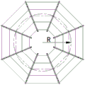
As shown in fig. 8, the equal-volume annular outer contour line, the manned cabin 3 outer contour line S1, the manned cabin 3 axis line S11, the equal-volume annular S2 axis line S21, the equal-volume annular S2 inner contour line S22 and the manned cabin 3 inner contour line S12 are arranged in sequence from left to right. The axis of the manned cabin 3 is formed by connecting the central points of the sections of the regular octagon, and the equal-volume annular axis is formed by connecting the central points of the sections of the annular circles. As can be seen from the figure, the axis of the manned cabin 3 is an inscribed octagon with an equal-volume annular axis, and the manned cabin 3 with various sections of inscribed polygon structures can be equivalently obtained by adopting the idea of the inscribed polygon.
The counting formula of the thickness of each part of the submersible is as follows:
the thickness of the manned cabin 3 is:
the thickness of the electrical compartment 4 is:
the thickness of the frustum-shaped shell 11 at the upper part of the ballast tank 1 is as follows:
the thickness of the cylindrical shell in the middle of the ballast tank 1 is as follows:
the thickness of the spherical shell is as follows: t is t3=Kt4Wherein t is4Satisfies the following conditions:
in the formula, K is a safety factor, and K is 1.5; rho is the density of the seawater; g is the acceleration of gravity, and h is the submergence depth; e is the Young's modulus of the material; μ is the Poisson's ratio of the material; r is1The radius of the large-diameter end of the frustum-shaped shell 11; r is2The radius of the small diameter end of the frustum-shaped shell 11; d is the radius of a polygon circumscribed circle of the cross section of the manned cabin unit 31; r is the radius of the axis of the manned cabin 3; r0Is the radius of the axis of the electric compartment 4; a, the length of the long diameter of the cross section of the electric cabin 4 unit; b electric cabin 4The length of the minor diameter of the cross section of the cell.
Although the embodiments of the present invention have been described in conjunction with the accompanying drawings, those skilled in the art may make various modifications and variations without departing from the spirit and scope of the invention, and such modifications and variations fall within the scope defined by the appended claims.