CN112309157B - Image display device - Google Patents
Image display device Download PDFInfo
- Publication number
- CN112309157B CN112309157B CN202010699852.XA CN202010699852A CN112309157B CN 112309157 B CN112309157 B CN 112309157B CN 202010699852 A CN202010699852 A CN 202010699852A CN 112309157 B CN112309157 B CN 112309157B
- Authority
- CN
- China
- Prior art keywords
- vehicle
- time
- unit
- sensor data
- delay
- Prior art date
- Legal status (The legal status is an assumption and is not a legal conclusion. Google has not performed a legal analysis and makes no representation as to the accuracy of the status listed.)
- Active
Links
Images


Classifications
-
- G—PHYSICS
- G05—CONTROLLING; REGULATING
- G05D—SYSTEMS FOR CONTROLLING OR REGULATING NON-ELECTRIC VARIABLES
- G05D1/00—Control of position, course, altitude or attitude of land, water, air or space vehicles, e.g. using automatic pilots
- G05D1/0011—Control of position, course, altitude or attitude of land, water, air or space vehicles, e.g. using automatic pilots associated with a remote control arrangement
- G05D1/0044—Control of position, course, altitude or attitude of land, water, air or space vehicles, e.g. using automatic pilots associated with a remote control arrangement by providing the operator with a computer generated representation of the environment of the vehicle, e.g. virtual reality, maps
-
- G—PHYSICS
- G08—SIGNALLING
- G08G—TRAFFIC CONTROL SYSTEMS
- G08G1/00—Traffic control systems for road vehicles
- G08G1/123—Traffic control systems for road vehicles indicating the position of vehicles, e.g. scheduled vehicles; Managing passenger vehicles circulating according to a fixed timetable, e.g. buses, trains, trams
-
- G—PHYSICS
- G08—SIGNALLING
- G08G—TRAFFIC CONTROL SYSTEMS
- G08G1/00—Traffic control systems for road vehicles
- G08G1/09—Arrangements for giving variable traffic instructions
- G08G1/0962—Arrangements for giving variable traffic instructions having an indicator mounted inside the vehicle, e.g. giving voice messages
- G08G1/0968—Systems involving transmission of navigation instructions to the vehicle
- G08G1/096855—Systems involving transmission of navigation instructions to the vehicle where the output is provided in a suitable form to the driver
-
- G—PHYSICS
- G05—CONTROLLING; REGULATING
- G05D—SYSTEMS FOR CONTROLLING OR REGULATING NON-ELECTRIC VARIABLES
- G05D1/00—Control of position, course, altitude or attitude of land, water, air or space vehicles, e.g. using automatic pilots
- G05D1/0011—Control of position, course, altitude or attitude of land, water, air or space vehicles, e.g. using automatic pilots associated with a remote control arrangement
- G05D1/0038—Control of position, course, altitude or attitude of land, water, air or space vehicles, e.g. using automatic pilots associated with a remote control arrangement by providing the operator with simple or augmented images from one or more cameras located onboard the vehicle, e.g. tele-operation
-
- G—PHYSICS
- G08—SIGNALLING
- G08G—TRAFFIC CONTROL SYSTEMS
- G08G1/00—Traffic control systems for road vehicles
- G08G1/01—Detecting movement of traffic to be counted or controlled
- G08G1/052—Detecting movement of traffic to be counted or controlled with provision for determining speed or overspeed
-
- G—PHYSICS
- G08—SIGNALLING
- G08G—TRAFFIC CONTROL SYSTEMS
- G08G1/00—Traffic control systems for road vehicles
- G08G1/09—Arrangements for giving variable traffic instructions
- G08G1/0962—Arrangements for giving variable traffic instructions having an indicator mounted inside the vehicle, e.g. giving voice messages
- G08G1/09626—Arrangements for giving variable traffic instructions having an indicator mounted inside the vehicle, e.g. giving voice messages where the origin of the information is within the own vehicle, e.g. a local storage device, digital map
-
- H—ELECTRICITY
- H04—ELECTRIC COMMUNICATION TECHNIQUE
- H04N—PICTORIAL COMMUNICATION, e.g. TELEVISION
- H04N5/00—Details of television systems
- H04N5/222—Studio circuitry; Studio devices; Studio equipment
- H04N5/262—Studio circuits, e.g. for mixing, switching-over, change of character of image, other special effects ; Cameras specially adapted for the electronic generation of special effects
- H04N5/272—Means for inserting a foreground image in a background image, i.e. inlay, outlay
-
- B—PERFORMING OPERATIONS; TRANSPORTING
- B60—VEHICLES IN GENERAL
- B60W—CONJOINT CONTROL OF VEHICLE SUB-UNITS OF DIFFERENT TYPE OR DIFFERENT FUNCTION; CONTROL SYSTEMS SPECIALLY ADAPTED FOR HYBRID VEHICLES; ROAD VEHICLE DRIVE CONTROL SYSTEMS FOR PURPOSES NOT RELATED TO THE CONTROL OF A PARTICULAR SUB-UNIT
- B60W60/00—Drive control systems specially adapted for autonomous road vehicles
- B60W60/001—Planning or execution of driving tasks
- B60W60/0025—Planning or execution of driving tasks specially adapted for specific operations
Landscapes
- Engineering & Computer Science (AREA)
- Radar, Positioning & Navigation (AREA)
- Remote Sensing (AREA)
- Physics & Mathematics (AREA)
- General Physics & Mathematics (AREA)
- Automation & Control Theory (AREA)
- Aviation & Aerospace Engineering (AREA)
- Signal Processing (AREA)
- Multimedia (AREA)
- General Engineering & Computer Science (AREA)
- Traffic Control Systems (AREA)
- Selective Calling Equipment (AREA)
- Instructional Devices (AREA)
- Closed-Circuit Television Systems (AREA)
Abstract
本发明提供能够向远程操作员通知合适的信息的图像显示装置。图像显示装置具备:外部传感器数据获取部,将由检测车辆的外部环境的信息的外部传感器在第一时刻检测出的外部传感器数据通过通信从车辆获取;内部传感器数据获取部,将由检测车辆的行驶状况的内部传感器在第一时刻检测出的内部传感器数据通过通信从车辆获取;确定部,基于第一时刻的内部传感器数据,确定从第一时刻起经过规定时间后的将来时刻的第二时刻的车辆的位置;以及显示控制部,基于第一时刻的外部传感器数据,使示出车辆的周边的监视图像显示于显示部,显示控制部使在与由确定部确定的第二时刻的车辆的位置对应的、监视图像上的位置处叠加示出第二时刻的车辆的位置的对象。

The present invention provides an image display device capable of notifying a remote operator of appropriate information. The image display device is provided with: an external sensor data acquisition unit that acquires external sensor data detected at a first moment by an external sensor that detects information on the external environment of the vehicle from the vehicle through communication; an internal sensor data acquisition unit that detects the vehicle’s driving condition The internal sensor data detected by the internal sensor at the first time is acquired from the vehicle through communication; the determination unit determines the vehicle at the second time in the future after a predetermined time has elapsed from the first time based on the internal sensor data at the first time. and the display control unit, based on the external sensor data at the first time, displays a surveillance image showing the periphery of the vehicle on the display unit, and the display control unit corresponds to the position of the vehicle at the second time determined by the determination unit An object showing the position of the vehicle at the second moment is superimposed on the position on the surveillance image.
Description
技术领域technical field
本公开涉及图像显示装置。The present disclosure relates to image display devices.
背景技术Background technique
专利文献1公开了基于从能够远程指示的自动驾驶车辆接收的照相机图像数据向远程操作员显示照相机图像的装置。该装置使叠加有与车辆的行驶相关联的信息的照相机图像显示于显示部。
专利文献1:日本特开2018-180771号公报Patent Document 1: Japanese Patent Laid-Open No. 2018-180771
远程操作员确认显示于显示部的照相机图像,对自动驾驶车辆进行远程指示。从将更合适的信息作为判断材料通知给远程操作员的观点而言,专利文献1所述的装置存在改善的余地。本公开提供能够向远程操作员通知合适的信息的图像显示装置。The remote operator confirms the camera image displayed on the display unit and gives remote instructions to the autonomous vehicle. The device described in
发明内容Contents of the invention
本公开的一个方面所涉及的图像显示装置与显示部连接,该显示部向对车辆进行远程指示的远程操作员显示信息。该图像显示装置具备:外部传感器数据获取部,将由获取车辆的外部环境的信息的外部传感器在第一时刻检测出的外部传感器数据通过通信从车辆获取;内部传感器数据获取部,将由获取车辆的行驶状况的内部传感器在第一时刻检测出的内部传感器数据通过通信从车辆获取;确定部,基于第一时刻的内部传感器数据,确定第二时刻的车辆的位置,第二时刻为从第一时刻起经过规定时间后的将来时刻;以及显示控制部,基于第一时刻的外部传感器数据,使示出车辆的周边的监视图像显示于显示部,显示控制部使与由确定部确定的第二时刻的车辆的位置对应的在监视图像上的位置处叠加示出第二时刻的车辆的位置的对象。An image display device according to one aspect of the present disclosure is connected to a display unit that displays information to a remote operator who remotely instructs a vehicle. The image display device includes: an external sensor data acquisition unit that acquires external sensor data detected at the first moment by an external sensor that acquires information on the external environment of the vehicle from the vehicle through communication; The internal sensor data detected by the internal sensor of the situation at the first moment is acquired from the vehicle through communication; the determination unit determines the position of the vehicle at the second moment based on the internal sensor data at the first moment, and the second moment is from the first moment A future time after a predetermined time has elapsed; and the display control unit, based on the external sensor data at the first time, displays a surveillance image showing the periphery of the vehicle on the display unit, and the display control unit makes a second time determined by the determination unit. The position of the vehicle corresponds to an object showing the position of the vehicle at the second moment superimposed on the position on the monitoring image.
在本公开的一个方面所涉及的图像显示装置中,基于由车辆的内部传感器检测出的第一时刻的内部传感器数据,计算第二时刻的车辆的位置。计算出的第二时刻的车辆的位置作为对象在基于第一时刻的外部传感器数据显示的监视图像上叠加显示,提供给远程操作员。因此,该图像显示装置能够将能够判断第一时刻的车辆状态是否维持到第二时刻的信息通知给远程操作员。In the image display device according to one aspect of the present disclosure, the position of the vehicle at the second time is calculated based on the internal sensor data at the first time detected by the internal sensor of the vehicle. The calculated position of the vehicle at the second time is superimposed on the monitoring image displayed based on the external sensor data at the first time as an object, and provided to the remote operator. Therefore, the image display device can notify the remote operator of information capable of judging whether the vehicle state at the first time is maintained until the second time.
在一个实施方式中,也可以是图像显示装置具备计算部,该计算部计算与车辆的通信的延迟时间,确定部基于延迟时间确定第二时刻的车辆的位置的可能的范围,显示控制部使在与范围对应的监视图像上的位置处叠加示出范围的对象。在该情况下,该图像显示装置能够向远程操作员通知产生了通信的延迟、以及该延迟对第二时刻的车辆的位置造成的影响。In one embodiment, the image display device may include a calculation unit that calculates the delay time of communication with the vehicle, the determination unit determines the possible range of the position of the vehicle at the second time based on the delay time, and the display control unit uses An object showing the range is superimposed at a position on the surveillance image corresponding to the range. In this case, the image display device can notify the remote operator of the delay in communication and the influence of the delay on the position of the vehicle at the second time.
在一个实施方式中,也可以是在延迟度为阈值以上的情况下,显示控制部使在与范围对应的、监视图像上的位置处叠加表示范围的对象,其中,该延迟度是基于延迟时间的绝对值及规定时间内的方差值之中至少一方而定义的,值越大则表示延迟越大。在该情况下,能够在延迟的程度小的情况下,该图像显示装置不通知远程操作员,在延迟的程度大的情况下,通知远程操作员。In one embodiment, when the degree of delay is equal to or greater than a threshold value, the display control unit may superimpose an object representing the range at a position on the monitoring image corresponding to the range, wherein the degree of delay is based on the delay time It is defined by at least one of the absolute value of and the variance value within a specified time. The larger the value, the larger the delay. In this case, the image display device can not notify the remote operator when the degree of delay is small, and can notify the remote operator when the degree of delay is large.
在一个实施方式中,也可以是示出第二时刻的车辆的位置的对象为基准线的对象,示出范围的对象是在基准线的对象的线宽方向上延伸的对象,延迟度越大,则显示控制部将示出范围的对象在线宽方向上的长度变更得越长。在该情况下,该图像显示装置能够使用基准线的对象和在该对象的线宽方向上延伸的对象,向远程操作员通知延迟的程度。In one embodiment, the object showing the position of the vehicle at the second moment may be the object of the reference line, and the object showing the range may be an object extending in the line width direction of the object of the reference line, and the greater the delay , the display control unit changes the length of the object in the display range in the line width direction to be longer. In this case, the image display device can notify the remote operator of the degree of delay using the object of the reference line and the objects extending in the line width direction of the object.
在一个实施方式中,确定部也可以基于第一时刻的外部传感器数据,检测在车辆的周边存在的其他车辆,并确定第二时刻的其他车辆的位置,显示控制部也可以使在与由确定部确定的第二时刻的其他车辆的位置对应的、监视图像上的位置处叠加示出第二时刻的其他车辆的位置的对象。在该情况下,该图像显示装置能够向远程操作员通知第二时刻的其他车辆的位置。In one embodiment, the determining unit can also detect other vehicles existing around the vehicle based on the external sensor data at the first moment, and determine the position of the other vehicles at the second moment, and the display control unit can also make the present and determined by An object showing the position of the other vehicle at the second time is superimposed at the position on the monitoring image corresponding to the position of the other vehicle at the second time determined by the Ministry of Public Security. In this case, the image display device can notify the remote operator of the position of the other vehicle at the second time.
发明的效果The effect of the invention
根据本公开,提供能够向远程操作员通知合适的信息的图像显示装置。According to the present disclosure, an image display device capable of notifying a remote operator of appropriate information is provided.
附图说明Description of drawings
图1是示出包括一个实施方式所涉及的图像显示装置的车辆远程指示系统的概要的图。FIG. 1 is a diagram showing an overview of a vehicle remote instruction system including an image display device according to an embodiment.
图2是示出远程指示装置的硬件构成的一个例子的图。FIG. 2 is a diagram showing an example of the hardware configuration of the remote pointing device.
图3是示出图像显示装置的功能的框图。FIG. 3 is a block diagram showing functions of the image display device.
图4的(A)是叠加有基准线的对象的监视图像的一个例子。图4的(B)是叠加有基准线的对象和示出延迟的对象的监视图像的一个例子。(A) of FIG. 4 is an example of a surveillance image of a subject on which a reference line is superimposed. (B) of FIG. 4 is an example of a monitor image on which a reference line object and a delayed object are superimposed.
图5的(A)是叠加有基准线的对象的监视图像的其他例子。图5的(B)是叠加有基准线的对象和示出延迟的对象的监视图像的其他例子。(A) of FIG. 5 is another example of a surveillance image of a subject on which a reference line is superimposed. (B) of FIG. 5 is another example of a monitor image on which a reference line object and a delayed object are superimposed.
图6是示出图像显示装置的显示处理的一个例子的流程图。FIG. 6 is a flowchart showing an example of display processing of the image display device.
图7是示出图像显示装置的显示处理的其他例子的流程图。FIG. 7 is a flowchart showing another example of display processing of the image display device.
图8的(A)是对其他车辆叠加有基准线的对象的监视图像的一个例子。图8的(B)是对特定的其他车辆叠加有基准线的对象和示出延迟的对象的监视图像的一个例子。(A) of FIG. 8 is an example of a surveillance image of an object on which a reference line is superimposed on another vehicle. (B) of FIG. 8 is an example of a surveillance image in which a baseline object and a delayed object are superimposed on a specific other vehicle.
图9是示出图像显示装置的确定处理的一个例子的流程图。FIG. 9 is a flowchart illustrating an example of identification processing by the image display device.
图10的(A)是叠加有基准线的对象的监视图像的其他例子。图10的(B)是叠加有基准线的对象和示出延迟的对象的监视图像的其他例子。(A) of FIG. 10 is another example of a surveillance image of a subject on which a reference line is superimposed. (B) of FIG. 10 is another example of a monitor image on which a reference line object and a delayed object are superimposed.
具体实施方式Detailed ways
以下,参照附图,对实施方式进行说明。另外,在以下的说明中,对相同或等同的要素标注相同的标号,并省略重复的说明。Embodiments will be described below with reference to the drawings. In addition, in the following description, the same code|symbol is attached|subjected to the same or equivalent element, and overlapping description is abbreviate|omitted.
图1是示出包括一个实施方式所涉及的图像显示装置的车辆远程指示系统的概要的图。图1所示的图像显示装置1包括在车辆远程指示系统100中。车辆远程指示系统100是基于远程操作员R的远程指示而使车辆2工作的系统。远程指示是指与车辆2的行动相关的远程操作员R的指示。对车辆2并无特别限定,作为一个例子,是以自动驾驶方式行驶的车辆。在以下,对车辆2是具有自动驾驶功能的车辆的情况进行说明。远程指示可以包括交叉路口的右转开始指示、带信号灯的交叉路口的进入开始指示、能见度差的交叉路口的进入开始指示、车道变更的开始指示、对前方障碍物的偏转避让开始指示、紧急疏散之中的至少一个。此外,远程指示也可以包括对原本处于泊车状态的车辆2进行的出发指示。远程指示也可以包括在原本处于停车状态的车辆2的周围检测到行人等的情况下对车辆2进行的出发指示。远程指示也可以包括与乘客针对车辆2上下车相关的指示(例如车门的自动开闭的指示、下车的声音引导开始的指示)。FIG. 1 is a diagram showing an overview of a vehicle remote instruction system including an image display device according to an embodiment. The
[车辆远程指示系统的构成][Configuration of Vehicle Remote Instruction System]
如图1所示,车辆远程指示系统100具备远程指示装置10。远程指示装置10具备图像显示装置1,与操作员接口3连接。操作员接口3在图像显示装置1的控制下,向远程操作员R显示信息。操作员接口3从远程操作员R接收远程指示,输出至远程指示装置10。远程指示装置10经由网络N与车辆2以能够通信的方式连接。网络N是无线通信网络。远程指示装置10从车辆2接收各种信息。另外,远程指示装置10也可以经由网络N与其他车辆以能够通信的方式连接。As shown in FIG. 1 , a vehicle remote instructing
在车辆远程指示系统100中,例如根据来自车辆2的远程指示请求,请求远程操作员R输入远程指示。远程操作员R对操作员接口3输入远程指示。远程指示装置10通过网络N向车辆2发送远程指示。车辆2依照远程指示自动地行驶。In the vehicle
在车辆远程指示系统100中,对远程操作员R的人数并无限定,可以为1人,也可以为2人以上。对能够与车辆远程指示系统100通信的车辆2的数量也并无限定。可以是多个远程操作员R交替对1台车辆2进行远程指示的形式,也可以是1个远程操作员R对2台以上的车辆2进行远程指示的形式。In the vehicle
作为一个例子,车辆2具有自动驾驶ECU(Electronic Control Unit)20。自动驾驶ECU 20是具有CPU(Central Processing Unit)、ROM(Read Only Memory)、RAM(RandomAccess Memory)等的电子控制单元。在自动驾驶ECU 20中,例如将记录于ROM的程序加载到RAM,由CPU执行加载到RAM的程序来实现各种功能。自动驾驶ECU 20也可以由多个电子单元构成。自动驾驶ECU 20与GPS(Global Positioning System)接收部21、外部传感器22、内部传感器23、地图数据库24、车辆通信部25及致动器26以能够通信的方式连接。As an example, the
GPS接收部21是从3个以上的GPS卫星接收信号的仪器。GPS接收部21基于接收到的信号来测定车辆2的位置(例如车辆2的纬度及经度)。GPS接收部21输出与测定出的位置相关的信息。GPS接收部21还输出按GPS的时间系统测量出的GPS时刻。The
外部传感器22是检测车辆2的外部环境的信息的传感器。外部传感器22将检测结果作为外部传感器数据输出。外部传感器22包括照相机。照相机是拍摄车辆2的外部环境的拍摄仪器。照相机输出与车辆2的外部环境相关的图像数据。图像数据是指能够描绘图像的信息。照相机例如设置在车辆2的前挡风玻璃的内侧,拍摄车辆前方。照相机可以是单眼照相机,也可以是立体照相机。照相机也可以设置多台,除了拍摄车辆2的前方之外,还可以拍摄左右侧向及后方。The
外部传感器22也可以包括雷达传感器。雷达传感器是利用电波(例如毫米波)或光来检测车辆2的周边的物体的检测仪器。雷达传感器包括例如毫米波雷达或光学雷达(LIDAR:Light Detection and Ranging)。雷达传感器通过向车辆2的周边发送电波或光并接收被物体反射回的电波或光,从而检测物体,并输出结果。物体除了包括护栏、建筑物等固定物体,还包括行人、自行车、其他车辆等移动物体。雷达传感器的检测结果能够被作为三维的图像数据来处置。
内部传感器23是检测车辆2的行驶状态的传感器。内部传感器23将检测结果作为内部传感器数据来输出。内部传感器23包括车速传感器、加速度传感器及偏航角速度传感器。车速传感器是检测车辆2的速度的检测器。作为车速传感器,可以使用针对车辆2的车轮或与车轮一体旋转的驱动轴等设置的、测量各车轮的转速的车轮速度传感器。The
加速度传感器是检测车辆2的加速度的检测器。加速度传感器例如包括检测车辆2的前后方向的加速度的前后加速度传感器。加速度传感器也可以包括检测车辆2的横向加速度的横向加速度传感器。偏航角速度传感器是检测绕车辆2重心的铅垂轴的偏航角速度(旋转角速度)的检测器。作为偏航角速度传感器,可以使用例如陀螺仪传感器。The acceleration sensor is a detector that detects the acceleration of the
地图数据库24是记录地图信息的数据库。地图数据库24例如形成在搭载于车辆2的HDD(Hard Disk Drive)等记录装置内。地图信息包括道路的位置信息、道路形状的信息(例如曲率信息)、交叉路口及岔路口的位置信息等。地图信息也可以包括与位置信息相关联的法定速度等交通管控信息。地图信息也可以包括用于获取车辆2的位置信息的标靶信息。作为标靶,可以使用道路标志、路面标识、信号灯、电线杆等。也可以在与车辆2能够通信的服务器中构成地图数据库24。The
车辆通信部25是控制与车辆2的外部进行的无线通信的通信设备。车辆通信部25经由网络N与远程指示装置10进行各种信息的发送及接收。车辆通信部25为了控制图像显示装置1,将外部传感器数据、内部传感器数据及GPS时刻发送至远程指示装置10。The
致动器26是用于车辆2的控制的仪器。致动器26包括驱动致动器、制动致动器及转向致动器。驱动致动器根据来自自动驾驶ECU 20的控制信号控制对发动机的空气供给量(节气门开度),控制车辆2的驱动力。另外,在车辆2是混合动力车的情况下,除了对发动机的空气供给量的控制之外,还向作为动力源的电动机输入来自自动驾驶ECU 20的控制信号,从而控制该驱动力。在车辆2是电动车的情况下,向作为动力源的电动机输入来自自动驾驶ECU 20的控制信号来控制该驱动力。作为这些情况下的动力源的电动机构成致动器26。The
制动致动器根据来自自动驾驶ECU 20的控制信号控制制动系统,控制赋予车辆2的车轮的制动力。作为制动系统,例如可以使用液压制动系统。转向致动器根据来自自动驾驶ECU 20的控制信号,对电动助力转向系统之中控制转向扭矩的辅助电动机的驱动进行控制。由此,转向致动器控制车辆2的转向扭矩。The brake actuator controls the brake system based on a control signal from the
自动驾驶ECU 20基于上述仪器的输出结果或仪器具有的信息,发挥各种功能。自动驾驶ECU 20具有车辆位置获取部200、外部环境识别部201、行驶状态识别部202、远程指示请求判定部203、轨迹生成部204、自动驾驶控制部205及紧急制动判定部206。The
车辆位置获取部200基于GPS接收部21的位置信息及地图数据库24的地图信息,获取车辆2的位置信息。此外,车辆位置获取部200也可以利用地图数据库24的地图信息所包括的标靶信息及外部传感器22的检测结果,通过SLAM(Simultaneous Localization andMapping)技术获取车辆2的位置信息。车辆位置获取部200也可以根据车道的分隔线与车辆2的位置关系,识别车辆2相对于车道的横向位置(车辆2在车道宽度方向上的位置),并将之包含在位置信息中。车辆位置获取部200还可以通过其他的公知的方法来获取车辆2的位置信息。The vehicle
外部环境识别部201基于外部传感器22的检测结果,识别车辆2的外部环境。外部环境包括周围的物体相对于车辆2的相对位置。外部环境也可以包括周围的物体相对于车辆2的相对速度及移动方向。外部环境也可以包括其他车辆、行人、自行车等物体的种类。可以通过模式匹配等公知的方法来识别物体的种类。外部环境也可以包括车辆2的周围的分隔线识别(白线识别)的结果。外部环境也可以包括信号灯的点亮状态的识别结果。外部环境识别部201例如能够基于外部传感器22的照相机图像,识别车辆2的前方的信号灯的点亮状态。The external
行驶状态识别部202基于内部传感器23的检测结果,识别车辆2的行驶状态。行驶状态包括车辆2的车速、车辆2的加速度、车辆2的偏航角速度。具体而言,行驶状态识别部202基于车速传感器的车速信息,识别车辆2的车速。行驶状态识别部202基于加速度传感器的车速信息,识别车辆2的加速度。行驶状态识别部202基于偏航角速度传感器的偏航角速度信息,识别车辆2的朝向。The running
远程指示请求判定部203判定是否应向远程操作员R请求远程指示。远程指示请求判定部203基于由车辆位置获取部200获取到的车辆2的位置信息及地图数据库24的地图信息、由外部环境识别部201识别出的外部环境、和后述的轨迹生成部204生成的轨迹之中的至少一者,判定是否应请求远程指示。The remote instruction
在车辆2处于预先设定的应请求远程指示的状况时,远程指示请求判定部203判定为应请求远程指示。例如在车辆2处于在交叉路口右转的状况时,远程指示请求判定部203判定为应请求远程指示。在车辆2处于进入带信号灯的交叉路口或能见度差的交叉路口的状况时,远程指示请求判定部203也可以判定为应请求远程指示。在车辆2处于为了到达目的地而开始车道变更的状况时,远程指示请求判定部203也可以判定应请求远程指示。在车辆2的前方存在应偏转避让的障碍物的情况下,远程指示请求判定部203也可以判定为应请求远程指示。When the
远程指示请求判定部203例如能够根据车辆2的位置信息、地图信息及轨迹,识别车辆2处于在交叉路口右转的状况、车辆2进入带信号灯的交叉路口的状况、或车辆2开始车道变更的状况。此外,远程指示请求判定部203能够基于车辆2的外部环境,识别在车辆2的前方存在应偏转避让的障碍物的情况。The remote instruction
远程指示请求判定部203在判定为应请求远程指示的情况下,对远程指示装置10请求来自远程操作员R的远程指示。远程指示的请求包括例如车辆2的识别信息。另外,远程指示请求判定部203也可以预先留有余量地请求远程指示。远程指示请求判定部203也可以在作为远程指示的对象的交叉路口等与车辆2的距离为一定距离以下的情况下,判定为应请求远程指示。也可以使用到达所剩时间而非距离。The remote instruction
远程指示请求判定部203在判定为应请求远程指示的情况下,将车辆2的行驶状况信息发送给远程指示装置10。车辆2的行驶状况信息包括用于远程操作员R识别车辆2的状况的信息。The remote instruction
车辆2的行驶状况信息包括车辆2的位置信息、由外部传感器22检测出的外部传感器数据及由内部传感器23检测出的内部传感器数据。外部传感器数据包括照相机图像、光学雷达的检测结果等。内部传感器数据包括车辆2的车速、车辆2的偏航角速度、车辆2的转向角等。车辆2的行驶状况信息也可以包括与乘客相关的信息(有无乘客、乘客的人数)。车辆2的行驶状况信息也可以包括与远程操作员R能够选择的远程指示相应的轨迹的信息。The running state information of the
自动驾驶ECU 20也可以不论是否应请求远程指示的判定结果如何,都在预先设定的定时将车辆2的行驶状况信息发送给远程指示装置10。预先设定的定时可以是每隔固定时间,也可以是地图上的道路的每个节点,还可以是接近人行横道时、接近交叉路口时等每个事件。The
轨迹生成部204生成车辆2的自动驾驶所利用的轨迹(trajectory)。轨迹生成部204基于预先设定的行驶路线、地图信息、车辆2的位置信息、车辆2的外部环境及车辆2的行驶状态,生成自动驾驶的轨迹。The
行驶路线是指在自动驾驶中车辆2行驶的路线。轨迹生成部204基于例如目的地、地图信息及车辆2的位置信息,求出自动驾驶的行驶路线。行驶路线也可以由公知的导航系统来设定。目的地可以由车辆2的乘客设定,也可以由自动驾驶ECU 20或导航系统等自动地提议。The traveling route refers to a route on which the
轨迹包括在自动驾驶下车辆行驶的路径(path)和自动驾驶中的车速曲线。路径是在行驶路线上正在自动驾驶的车辆行驶的规定轨迹。路径可以设为例如与行驶路线上的位置相应的车辆2的转向角变化的数据(转向角曲线)。行驶路线上的位置是指例如在行驶路线的行进方向上每隔规定间隔(例如1m)设定的设定纵向位置。转向角曲线是指每个设定纵向位置与目标转向角关联而成的数据。The trajectory includes a path (path) traveled by the vehicle under automatic driving and a vehicle speed profile during automatic driving. A path is a prescribed trajectory that a vehicle that is driving autonomously travels on a travel route. The route can be, for example, data (steering angle profile) of changes in the steering angle of the
轨迹生成部204例如基于行驶路线、地图信息、车辆2的外部环境及车辆2的行驶状态,生成车辆2行驶的路径。轨迹生成部204生成路径,以使例如车辆2经过行驶路线所包括的车道的中央(车道宽度方向上的中央)。The
车速曲线例如是每个设定纵向位置与目标车速关联而成的数据。设定纵向位置也可以不以距离而以车辆2的行驶时间为基准来设定。设定纵向位置也可以被设定为车辆1秒后的到达位置、车辆2秒后的到达位置。The vehicle speed profile is, for example, data in which each set longitudinal position is associated with a target vehicle speed. The set longitudinal position may be set on the basis of the travel time of the
轨迹生成部204基于例如路径和地图信息所包括的法定速度等交通管控信息,生成车速曲线。也可以代替法定速度,而使用针对地图上的位置或区间预先设定的设定速度。轨迹生成部204根据路径及车速曲线生成自动驾驶的轨迹。另外,轨迹生成部204中的轨迹的生成方法不限于上述内容,可以采用与自动驾驶相关的公知的方法。关于轨迹的内容也是同样。The
在由远程指示请求判定部203对远程指示装置10请求了远程指示的情况下,轨迹生成部204预先生成与远程指示相应的轨迹。远程指示的内容根据车辆2的状况而预先确定。例如交叉路口右转时的远程指示的内容包括右转开始(行进开始)的远程指示及等待的远程指示。交叉路口右转时的远程指示的内容可以包括放弃右转而直行的远程指示,也可以包括紧急疏散的远程指示。When the remote instruction
例如在车辆2处于在交叉路口右转的状况下,轨迹生成部204以与右转开始的远程指示对应的方式生成车辆2在交叉路口右转的轨迹。在接收到远程指示之前,轨迹生成部204也可以根据外部环境的变化来更新轨迹。此外,在存在从在交叉路口右转切换到在交叉路口直行的远程指示的情况下,轨迹生成部204也可以预先生成在交叉路口直行的轨迹。For example, when the
在存在紧急疏散的远程指示的情况下,轨迹生成部204也可以预先生成用于紧急疏散的轨迹。以使车辆2在地图上预先设定的任意的疏散空间停车的方式生成用于紧急疏散的轨迹。轨迹生成部204例如基于外部环境识别各疏散空间中有无障碍物,以在空闲疏散空间停车的方式生成用于紧急疏散的轨迹。另外,轨迹生成部204并非必须预先生成轨迹,也可以在接收了远程指示之后生成与远程指示对应的轨迹。When there is a remote instruction for emergency evacuation, the
自动驾驶控制部205执行车辆2的自动驾驶。自动驾驶控制部205例如基于车辆2的外部环境、车辆2的行驶状态及轨迹生成部204生成的轨迹,执行车辆2的自动驾驶。自动驾驶控制部205通过向致动器26发送控制信号,来进行车辆2的自动驾驶。The automatic
在由远程指示请求判定部203对远程指示装置10请求了远程指示的情况下,自动驾驶控制部205等待接收来自远程指示装置10的远程指示。在车辆2停车之后请求了远程指示的情况下,自动驾驶控制部205维持停车状态,直至接收到远程指示。When the remote instruction
在具有驾驶证的乘客乘车的情况下,也可以在经过预先设定的等待时间后没有接收到远程指示时,自动驾驶控制部205请求该乘客进行判断或手动驾驶。也可以在经过等待时间后没有接收到远程指示、且乘客无法进行判断或无法手动驾驶的情况下,自动驾驶控制部205自动进行紧急疏散。When a passenger with a driver's license boards the vehicle, the automatic
紧急制动判定部206基于车辆2的外部环境或外部传感器22的检测结果(照相机的图像和/或雷达传感器的物体信息),判定是否要紧急制动。例如在车辆2的前方的障碍物与车辆2的碰撞剩余时间(TTC:Time To Collision)小于TTC阈值的情况下,紧急制动判定部206判定需要紧急制动。TTC阈值是预先设定有值的阈值。另外,可以使用车车间时间(THW:Time Headway)代替碰撞剩余时间,也可以使用车辆2与障碍物的距离代替碰撞剩余时间。The emergency
在判定需要紧急制动的情况下,紧急制动判定部206向制动致动器发送控制信号并执行紧急制动。紧急制动的判定独立于自动驾驶功能而执行。紧急制动判定部206也可以形成于与自动驾驶ECU 20不同的电子单元中。紧急制动也可以在所谓的PCS(Pre-CrashSafety)系统中执行。When it is determined that emergency braking is necessary, emergency
[远程指示装置的构成][Configuration of remote pointing device]
图2是示出远程指示装置的硬件构成的一个例子的图。如图2所示,远程指示装置10可以构成为具备处理器10a、存储部10b、通信部10c及用户接口10d的普通的计算机。FIG. 2 is a diagram showing an example of the hardware configuration of the remote pointing device. As shown in FIG. 2 , the
处理器10a使各种操作系统工作来控制远程指示装置10。处理器10a是包括控制装置、运算装置、寄存器等的CPU等运算器。处理器10a集中管理存储部10b、通信部10c及用户接口10d。存储部10b包括存储器(memory)和储存器(storage)的至少其中一种。存储器是ROM、RAM等存储介质。储存器是HDD等存储介质。The
通信部10c是用于进行经由网络N的通信的通信仪器。通信部10c可以采用网络设备、网络控制器、网卡等。用户接口10d是管理员等用户使用的输入输出部。用户接口10d包括显示器、扬声器等输出器和触摸面板等输入器。远程指示装置10并非必须设置于设施中,也可以搭载于车辆等移动体中。The
[图像显示装置的构成及功能][Structure and Function of Image Display Device]
由于图像显示装置1包括在远程指示装置10中,所以其硬件与远程指示装置10相同。图像显示装置1的硬件不限于与远程指示装置10相同或者共通的情况,也可以独立于远程指示装置10而单独具备图2的构成。图3是示出图像显示装置的功能的框图。如图3所示,图像显示装置1包括作为通信功能的通信部11。通信部11的功能由处理器10a及通信部10c实现。Since the
通信部11经由网络N与车辆2的车辆通信部25连接。车辆2的车辆通信部25具有外部传感器数据发送部250、内部传感器数据发送部251及时间发送部252,用于发送外部传感器数据、内部传感器数据及GPS时刻。通信部11具有外部传感器数据接收部110(外部传感器数据获取部的一个例子)、内部传感器数据接收部111(内部传感器数据获取部的一个例子)及时间接收部112,用于接收外部传感器数据、内部传感器数据及GPS时刻。外部传感器数据接收部110经由网络N从车辆2的外部传感器数据发送部250获取由车辆2的外部传感器22在第一时刻检测出的外部传感器数据。内部传感器数据接收部111经由网络N从车辆2的内部传感器数据发送部251获取由车辆2的内部传感器23在第一时刻检测出的内部传感器数据。第一时刻是指外部传感器22及内部传感器23的检测时刻。时间接收部112经由网络N从车辆2的时间发送部252获取GPS时刻。The
图像显示装置1除了具备通信部11外,还具备延迟时间计算部12(计算部的一个例子)、辅助信息生成部13(确定部的一个例子)及显示控制部14。The
延迟时间计算部12计算与车辆2的通信的延迟时间。延迟时间计算部12通过将由时间接收部112获取的GPS时刻和由图像显示装置1的未图示的GPS接收部获取的GPS时刻进行比较,来计算通信的延迟时间。The delay
辅助信息生成部13生成作为辅助远程操作员R的判断的信息的辅助信息。辅助信息生成部13确定作为从第一时刻经过规定时间后的将来时刻的第二时刻的车辆2的位置。将来时刻是指在当前时刻之后的时刻。在以图像显示装置1的处理时为基准的情况下,第一时刻是与当前时刻非常接近的过去的时刻,第二时刻是比当前时刻更靠后的将来的时刻。第二时刻也可以设定多个。辅助信息生成部13基于由内部传感器数据接收部111获取的第一时刻的传感器数据,确定第二时刻的车辆2的位置。作为一个例子,辅助信息生成部13假定从第一时刻到第二时刻为止由远程操作员R进行的远程指示没有变化,基于第一时刻的传感器数据确定第二时刻的车辆2的位置。例如在第一时刻的车速为60km/h的情况下,辅助信息生成部13假定直至第二时刻车速都维持在60km/h。例如在第一时刻正在减速的情况下,辅助信息生成部13假定直至第二时刻都以相同的加速度减速。像这样,辅助信息生成部13确定在车辆2的行驶状态没有变化的情况下的将来的车辆2的位置。The auxiliary
辅助信息生成部13也可以基于由延迟时间计算部12计算出的延迟时间,确定第二时刻的车辆2的位置的可能的范围。例如在车速为60km/h且延迟时间为0.1秒的情况下,产生1.7m程度的误差。辅助信息生成部13例如确定从基于第一时刻的传感器数据确定的第二时刻的车辆2的位置减去误差的量的距离得到的最大延迟位置。辅助信息生成部13也可以将从最大延迟位置至第二时刻的车辆2的位置为止的范围确定为可能的范围。辅助信息生成部13也可以利用第二时刻的车辆2的位置、误差的距离和正态分布,来确定可能的范围。The auxiliary
显示控制部14基于由外部传感器数据接收部110获取的第一时刻的外部传感器数据,使操作员接口3显示示出车辆2的周边的监视图像。操作员接口3具备显示装置30(显示部的一个例子)。显示控制部14与显示装置30连接。监视图像是在显示装置30的画面显示的图像,只要是示出车辆2的周围的图像即可。例如监视图像可以是从正上方俯瞰车辆2而成的图或是从斜向俯瞰车辆2而成的鸟瞰图,也可以是由外部传感器22获取的照相机图像或雷达传感器的图像本身。另外,操作员接口3除了包括显示装置30,还可以包括远程操作员R的操作用的指示受理部31。The
显示控制部14使在与由辅助信息生成部13确定的第二时刻的车辆2的位置对应的、监视图像上的位置处叠加示出第二时刻的车辆2的位置的对象。作为一个例子,示出第二时刻的车辆2的位置的对象是基准线的对象。例如基准线的对象是实线、虚线、点划线等对象,能够带有各种颜色。示出第二时刻的车辆2的位置的对象不限于这些。例如示出第二时刻的车辆2的位置的对象也可以是圆形、矩形。The
图4的(A)是叠加有基准线的对象的监视图像的一个例子。图4的(A)的监视图像G1是示出车辆2的车辆对象OV1位于画面中央而成的俯瞰图。作为一个例子,辅助信息生成部13生成从当前时刻起1秒后、2秒后及3秒后这3个第二时刻的车辆2的位置。显示控制部14基于由辅助信息生成部13确定的3个第二时刻的车辆2的位置,在监视图像G1上叠加显示各个基准线的对象。例如显示控制部14在监视图像G1上叠加显示示出1秒后的车辆2的位置的、包围车辆2的周围的线对象OL1。显示控制部14能够在与线对象OL1对应的画面位置处叠加显示示出与第二时刻相关联的信息(例如从当前时刻起的经过时间)的对象M1。同样地,显示控制部14叠加显示示出2秒后的车辆2的位置的线对象OL2及与对应的第二时刻相关联的对象M2。显示控制部14叠加显示示出3秒后的车辆2的位置的线对象OL3及与对应的第二时刻相关联的对象M3。(A) of FIG. 4 is an example of a surveillance image of a subject on which a reference line is superimposed. The monitoring image G1 of (A) of FIG. 4 is a bird's-eye view showing that the vehicle object OV1 of the
显示控制部14也可以将与延迟时间相关的对象叠加显示于监视图像。例如显示控制部14也可以将由辅助信息生成部13确定的可能的范围作为对象叠加显示于监视图像。示出可能的范围的对象可以是透明度高的图形,也可以带有各种颜色。图4的(B)是基准线的对象和示出延迟的对象叠加而成的监视图像的一个例子。图4的(B)的监视图像G2是示出车辆2的车辆对象OV1位于画面中央而成的俯瞰图。在以下,以将示出延迟的对象追加显示在图4的(A)的监视图像的情况为例进行说明。作为一个例子,辅助信息生成部13针对从当前时刻起1秒后、2秒后及3秒后这3个第二时刻之中的各个第二时刻,确定可能的范围。显示控制部14基于来自辅助信息生成部13的、与3个第二时刻对应的可能的范围,使各个对象叠加显示在监视图像G2上。例如显示控制部14以示出1秒后的车辆2的可能的范围的方式,叠加显示在线对象OL1的线宽方向上延伸的对象B1。同样地,显示控制部14以示出2秒后的车辆2的可能的范围的方式,叠加显示在线对象OL2的线宽方向上延伸的对象B2。显示控制部14以示出3秒后的车辆2的可能的范围的方式,叠加显示在线对象OL3的线宽方向上延伸的对象B3。The
显示控制部14也可以以对象B1~B3在线宽方向上的长度来示出延迟的大小。例如显示控制部14使用由辅助信息生成部13计算出的延迟时间来确定延迟度。延迟度是示出延迟时间越长则延迟越大的情况的值。延迟度可以是延迟时间的绝对值。显示控制部14也可以使用由辅助信息生成部13计算出的延迟时间在规定时间段内的方差值来确定延迟度。在该情况下,延迟度是示出方差值越大则延迟越大的情况的值。延迟度也可以是方差值本身。或者,延迟度也可以是延迟时间的延迟度和方差值的延迟度的加权和、加权平均。或者也可以基于延迟时间的绝对值与方差值的关系来确定延迟度。具体而言,延迟度可以为如下的情况:在延迟时间的绝对值比规定阈值小的情况下,不论延迟时间的方差值如何(即使延迟时间的方差值大),都将延迟度确定得小;另一方面,在延迟时间的绝对值为规定阈值以上的情况下,确定为延迟时间的方差值越大则延迟度越大,延迟时间的方差值越小则延迟度越小。像这样,基于延迟时间的绝对值及规定时间内的方差值之中的至少一方来定义延迟度。显示控制部14能够通过延迟度越大则将对象B1~B3在线宽方向上的长度变更得越长的方式,来表现延迟的大小。The
显示控制部14也可以根据条件来切换图4的(A)的监视图像G1与图4的(B)的监视图像G2。例如,在延迟度小于阈值的情况下,显示控制部14使图4的(A)的监视图像G1显示于显示装置30,在延迟度为阈值以上的情况下,显示控制部14使图4的(B)的监视图像G2显示于显示装置30。阈值是为了判定延迟度而预先设定的值。例如,阈值也可以由显示于监视图像的基准线的间隔和设定比例来确定。例如,以延迟时间为延迟度的情况为例,在基准线的间隔为1秒,设定比例为0.5的情况下,阈值被设定为0.5秒。在该情况下,在延迟时间小于0.5秒的情况下,显示控制部14显示监视图像G1,在延迟时间为0.5秒以上的情况下,显示控制部14显示监视图像G2。The
图5的(A)是叠加有基准线的对象的监视图像的其他例子。如上所述,基准线的对象可以以各种方式来表现。在图5的(A)的监视图像G3中,示出了示出车辆2的车辆对象OV1和其规定路径PA。为了如此显示,图像显示装置1经由通信部11从车辆2预先获取规定路径。显示控制部14基于由辅助信息生成部13确定的5个第二时刻的车辆2的位置,使各个基准线的对象叠加显示在监视图像G1的规定路径PA上。例如,显示控制部14使示出1秒后的车辆2的位置的线对象OL1叠加显示在监视图像G1上。显示控制部14能够在与线对象OL1对应的画面位置处,叠加显示示出与第二时刻相关联的信息(例如从当前时刻起的经过时间)的对象M1。此时,显示控制部14也可以为了对象的形状而参照地图信息。同样地,显示控制部14叠加显示示出2秒后的车辆2的位置的线对象OL2及与对应的第二时刻相关联的对象M2。显示控制部14叠加显示示出3秒后的车辆2的位置的线对象OL3及与对应的第二时刻相关联的对象M3。显示控制部14叠加显示示出4秒后的车辆2的位置的线对象OL4及与对应的第二时刻相关联的对象M4。显示控制部14叠加显示示出5秒后的车辆2的位置的线对象OL5及与对应的第二时刻相关联的对象M5。(A) of FIG. 5 is another example of a surveillance image of a subject on which a reference line is superimposed. As mentioned above, the objects of the baseline can be represented in various ways. In the monitoring image G3 of (A) of FIG. 5 , a vehicle object OV1 showing a
图5的(B)是叠加有基准线的对象和示出延迟的对象的监视图像的其他例子。在图5的(B)中,如在图4的(B)中说明的那样,是针对图5的(A)的监视图像G3追加显示示出延迟的对象B1~B5而成的画面。对象B1~B5的设定方法、监视图像的切换方法等与上述内容相同。(B) of FIG. 5 is another example of a monitor image on which a reference line object and a delayed object are superimposed. In (B) of FIG. 5 , as described in (B) of FIG. 4 , objects B1 to B5 showing delays are additionally displayed on the monitor image G3 of (A) of FIG. 5 . The setting method of the objects B1 to B5, the switching method of the monitoring image, and the like are the same as those described above.
[图像显示装置的工作][Operation of Image Display Device]
图6是示出图像显示装置的显示处理的一个例子的流程图。图6所示的流程图在发生了图像显示装置1的显示功能的开始指示的定时开始。FIG. 6 is a flowchart showing an example of display processing of the image display device. The flowchart shown in FIG. 6 starts at the timing when an instruction to start the display function of the
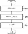
首先,作为数据获取处理(S10),外部传感器数据接收部110从车辆2获取在第一时刻检测出的外部传感器数据。内部传感器数据接收部111从车辆2获取第一时刻的内部传感器数据。First, as data acquisition processing ( S10 ), the external sensor
接下来,作为辅助信息生成处理(S12),辅助信息生成部13假定从第一时刻至第二时刻为止由远程操作员R进行的远程指示没有变化,确定第二时刻的车辆2的位置。Next, as auxiliary information generation processing ( S12 ), the auxiliary
接下来,作为显示处理(S14),显示控制部14基于第一时刻的外部传感器数据使示出车辆2的周边的监视图像显示于显示装置30,并在与由辅助信息生成部13确定的第二时刻的车辆2的位置对应的、监视图像上的位置处叠加示出第二时刻的车辆2的位置的对象。Next, as a display process (S14), the
在显示处理(S14)结束后,图6所示的流程图结束。通过执行图6所示的流程图,图像显示装置1能够向远程操作员R合适地通知将来的车辆2的位置。在流程图结束后,在收到显示功能的结束指示之前,图像显示装置1从头开始流程图。After the display processing (S14) ends, the flowchart shown in FIG. 6 ends. By executing the flowchart shown in FIG. 6 , the
图7是示出图像显示装置的显示处理的其他例子的流程图。在图7所示的流程图中,图像显示装置1根据条件向远程操作员R通知延迟时间。图7所示的流程图在发生了图像显示装置1的显示功能的开始指示的定时开始。FIG. 7 is a flowchart showing another example of display processing of the image display device. In the flowchart shown in FIG. 7 , the
首先,作为数据获取处理(S20),外部传感器数据接收部110从车辆2获取在第一时刻检测出的外部传感器数据。内部传感器数据接收部111从车辆2获取第一时刻的内部传感器数据。First, as data acquisition processing ( S20 ), the external sensor
接下来,作为GPS时刻获取处理(S22),时间接收部112从车辆2获取GPS时刻。此外,延迟时间计算部12从图像显示装置1的未图示的GPS接收部获取自身的GPS时刻。Next, the
接下来,作为延迟度计算处理(S24),延迟时间计算部12比较车辆2的GPS时刻和自身的GPS时刻而计算延迟度。作为一个例子,延迟时间计算部12将作为车辆2的GPS时刻与自身的GPS时刻之差的延迟时间用作延迟度。延迟时间计算部12也可以在规定时间的期间,计算车辆2的GPS时刻与自身的GPS时刻之差,将该差的方差值用作延迟度。Next, as the delay degree calculation process ( S24 ), the delay
接下来,作为判定处理(S26),辅助信息生成部13判定延迟度是否为阈值以上。在延迟度不为阈值以上的情况下,作为辅助信息生成处理(S28),辅助信息生成部13假定从第一时刻到第二时刻为止远程操作员R进行的远程指示没有变化,确定第二时刻的车辆2的位置。在延迟度为阈值以上的情况下,作为辅助信息生成处理(S30),辅助信息生成部13假定从第一时刻到第二时刻为止远程操作员R进行的远程指示没有变化,确定第二时刻的车辆2的位置,并基于延迟时间确定车辆2的可能的范围。Next, as a determination process ( S26 ), the auxiliary
在辅助信息生成处理(S28或S30)结束后,作为显示处理(S32),显示控制部14基于第一时刻的外部传感器数据使示出车辆2的周边的监视图像显示于显示装置30,并在与由辅助信息生成部13确定的第二时刻的车辆2的位置对应的、监视图像上的位置处叠加示出第二时刻的车辆2的位置的对象。在由辅助信息生成部13确定了车辆2的可能的范围的情况下,显示控制部14还使示出车辆2的可能的范围的对象叠加显示在监视图像上。After the supplementary information generation process (S28 or S30) is completed, as a display process (S32), the
在显示处理(S32)结束后,图7所示的流程图结束。通过执行图7所示的流程图,图像显示装置1能够根据条件向远程操作员R通知延迟时间。在流程图结束后,在收到显示功能的结束指示之前,图像显示装置1从头开始流程图。After the display processing (S32) ends, the flowchart shown in FIG. 7 ends. By executing the flowchart shown in FIG. 7 , the
[实施方式的总结][Summary of Embodiment]
在一个实施方式所涉及的图像显示装置1中,基于由车辆2的内部传感器23检测出的第一时刻的内部传感器数据,计算在从第一时刻到第二时刻为止远程操作员R进行的远程指示没有变化的情况下的第二时刻的车辆2的位置。计算出的第二时刻的车辆2的位置被作为对象叠加显示于基于第一时刻的外部传感器数据显示的监视图像上,向远程操作员R提供。因此,该图像显示装置1能够向远程操作员R通知能够判断第一时刻的车辆状态是否维持至第二时刻的信息。In the
图像显示装置1能够向远程操作员R通知产生了通信的延迟和该延迟对第二时刻的车辆的位置造成的影响。图像显示装置1能够在延迟的程度小的情况下不通知远程操作员R,而在延迟的程度大的情况下通知远程操作员R。图像显示装置1能够使用基准线的对象和在该对象的线宽方向上延伸的对象来向远程操作员R通知延迟的程度。The
以上,对本公开的实施方式进行了说明,但本公开不限于上述实施方式。本公开能够基于上述实施方式,以基于本领域普通技术人员的知识而进行了各种变更、改良的各种方式来实施。The embodiments of the present disclosure have been described above, but the present disclosure is not limited to the above-described embodiments. The present disclosure can be implemented in various forms with various changes and improvements based on the above-described embodiments based on the knowledge of those skilled in the art.
[变形例][modified example]
[其他车辆的显示][Display of other vehicles]
图像显示装置1也可以将与在车辆2的周边存在的其他车辆相关的信息显示于显示装置30。图像显示装置1基于由外部传感器22检测出的外部传感器数据来识别其他车辆,针对其他车辆显示基于车辆2显示的辅助信息。The
图8的(A)是对其他车辆叠加有基准线的对象的监视图像的一个例子。图8的(A)的监视图像G5是包括示出车辆2的车辆对象OV1以及示出车辆2的周边的其他车辆的车辆对象OV2、OV3的俯瞰图。作为一个例子,辅助信息生成部13生成从当前时刻起1秒后、2秒后、及3秒后的3个第二时刻的其他车辆的位置。显示控制部14基于由辅助信息生成部13确定的3个第二时刻的其他车辆的位置,使各个基准线的对象叠加显示在监视图像G5上。例如,显示控制部14以示出1秒后的其他车辆的位置的方式,使包围其他车辆的周围的线对象叠加显示在监视图像G5上。显示控制部14能够在与线对象对应的画面位置处叠加显示示出与第二时刻相关联的信息(例如从当前时刻起的经过时间)的对象。同样地,显示控制部14叠加显示示出2秒后的其他车辆的位置的线对象及与对应的第二时刻相关联的对象。显示控制部14叠加显示示出3秒后的其他车辆的位置的线对象及与对应的第二时刻相关联的对象。(A) of FIG. 8 is an example of a surveillance image of an object on which a reference line is superimposed on another vehicle. The surveillance image G5 of FIG. 8(A) is a bird's-eye view including a vehicle object OV1 showing the
在图8的(A)中,针对在车辆2的周边存在的全部其他车辆进行了辅助信息的显示,但也可以仅针对特定的其他车辆进行辅助信息的显示。此外,在图8的(A)中,也可以显示在线对象的线宽方向上延伸的对象,也可以进行考虑到延迟时间的显示。In (A) of FIG. 8 , the auxiliary information is displayed for all other vehicles existing around the
图8的(B)是对特定的其他车辆叠加有基准线的对象和示出延迟的对象的监视图像的一个例子。在图8的(B)的监视图像G6中,车辆对象OV2被作为显示对象的车辆而选择,仅针对车辆对象OV2显示辅助信息。图像显示装置1通过执行以下的图9的流程图来选择显示对象的车辆。(B) of FIG. 8 is an example of a surveillance image in which a baseline object and a delayed object are superimposed on a specific other vehicle. In the monitoring image G6 of FIG. 8(B), the vehicle object OV2 is selected as a vehicle to be displayed, and the auxiliary information is displayed only for the vehicle object OV2. The
图9是示出图像显示装置的确定处理的一个例子的流程图。图9所示的流程图在产生了图像显示装置1的显示功能的开始指示的定时开始。FIG. 9 is a flowchart illustrating an example of identification processing by the image display device. The flowchart shown in FIG. 9 starts at the timing when an instruction to start the display function of the
首先,作为数据获取处理(S40),外部传感器数据接收部110从车辆2获取由外部传感器22在第一时刻检测出的外部传感器数据。First, as data acquisition processing ( S40 ), the external sensor
接下来,作为评估值计算处理(S42),图像显示装置1基于外部传感器数据来识别其他车辆的位置。并且,图像显示装置1针对识别出的每台其他车辆计算评估值。评估值是表示安全性的指标,作为一个例子,是表示对车辆2的行动造成的影响是否大的值。评估值的值越大,则表示对车辆2的行动造成的影响越大。即,评估值越大则安全性越低。例如,图像显示装置1通过将车辆2与对象的其他车辆的相对速度、相对偏航角、相对距离等进行加权和,来计算评估值。加权和也可以包括与对象的其他车辆的车型相应的项。Next, as evaluation value calculation processing ( S42 ), the
接下来,作为显示对象确定处理(S44),图像显示装置1基于针对每台其他车辆计算出的评估值来确定作为显示对象的其他车辆。图像显示装置1选择评估值最高的其他车辆。Next, as a display target determination process ( S44 ), the
在显示对象确定处理(S44)结束后,图9所示的流程图结束。在图9所示的流程图结束后,针对作为显示对象的其他车辆生成辅助信息并显示。关于辅助信息的生成及显示,与图6及图7的流程图相同。通过执行图9所示的流程图,图像显示装置1能够从多台其他车辆选择安全性低的其他车辆并显示辅助信息。在流程图结束后,在收到显示功能的结束指示之前,图像显示装置1从头开始流程图。After the display object specifying process (S44) ends, the flowchart shown in FIG. 9 ends. After the flowchart shown in FIG. 9 is completed, auxiliary information is generated and displayed for other vehicles to be displayed. The generation and display of auxiliary information are the same as the flowcharts in FIGS. 6 and 7 . By executing the flowchart shown in FIG. 9 , the
[显示的变形例][Modified example of display]
在实施方式中,显示控制部14使俯瞰图像显示于显示装置30,但也可以显示照相机图像本身。图10的(A)是叠加有基准线的对象的监视图像的其他例子。如图10的(A)所示,监视图像G7是照相机图像,叠加显示有示出将来的车辆2的位置的线对象OL1~OL4和与对应的时刻相关联的对象M1~M4。图10的(B)是叠加有基准线的对象和示出延迟的对象的监视图像的其他例子。如图10的(B)所示,监视图像G8是照相机图像,叠加显示示出将来的车辆2的位置的线对象OL1~OL4、与对应的时刻相关联的对象M1~M4、及在线对象OL1~OL4的线宽方向上根据延迟时间而延伸的对象B1~B4。像这样,图像显示装置1也可以使辅助信息叠加于照相机图像。In the embodiment, the
在其他车辆的显示所涉及的变形例中,显示控制部14使示出将来的其他车辆的位置的线对象进行显示,但不限于此。例如显示控制部14也可以使示出车辆2和对象的其他车辆的TTC的线对象进行显示。In the modified example related to the display of other vehicles, the
[构成的变形例][modified example of constitution]
车辆2只要是能够进行远程指示的车辆即可,不限于自动驾驶车辆。车辆2也可以不具备地图数据库。在省略了与延迟时间相关的显示的情况下,图像显示装置1也可以不具备时间接收部112及延迟时间计算部12。此外,图像显示装置1也可以使用从NTP(NetworkTime Protocol)服务器获取的时刻来代替GPS时刻。The
标号的说明Explanation of labels
1:图像显示装置;2:车辆;14:显示控制部;22:外部传感器;23:内部传感器;R:远程操作员。1: image display device; 2: vehicle; 14: display control unit; 22: external sensor; 23: internal sensor; R: remote operator.
Claims (4)
Applications Claiming Priority (2)
| Application Number | Priority Date | Filing Date | Title |
|---|---|---|---|
| JP2019-135626 | 2019-07-23 | ||
| JP2019135626A JP7238670B2 (en) | 2019-07-23 | 2019-07-23 | image display device |
Publications (2)
| Publication Number | Publication Date |
|---|---|
| CN112309157A CN112309157A (en) | 2021-02-02 |
| CN112309157B true CN112309157B (en) | 2022-11-29 |
Family
ID=74187558
Family Applications (1)
| Application Number | Title | Priority Date | Filing Date |
|---|---|---|---|
| CN202010699852.XA Active CN112309157B (en) | 2019-07-23 | 2020-07-20 | Image display device |
Country Status (3)
| Country | Link |
|---|---|
| US (1) | US11636762B2 (en) |
| JP (3) | JP7238670B2 (en) |
| CN (1) | CN112309157B (en) |
Families Citing this family (17)
| Publication number | Priority date | Publication date | Assignee | Title |
|---|---|---|---|---|
| WO2021124516A1 (en) * | 2019-12-19 | 2021-06-24 | 株式会社ガク・アソシエイツ | Boundary visualization system, boundary visualization method, boundary visualization program, and digital photo-album preparation system |
| US11796997B1 (en) * | 2020-03-25 | 2023-10-24 | Gm Cruise Holdings Llc | Emergency vehicle interactions using external triggers |
| JP7400754B2 (en) * | 2021-02-24 | 2023-12-19 | トヨタ自動車株式会社 | Remote support system and remote support method |
| JP7459821B2 (en) * | 2021-02-25 | 2024-04-02 | 株式会社デンソー | Remote support system, remote support method, and remote support program |
| JP7501470B2 (en) | 2021-08-19 | 2024-06-18 | トヨタ自動車株式会社 | Driving image display method and driving image display system |
| JP7512985B2 (en) | 2021-08-31 | 2024-07-09 | トヨタ自動車株式会社 | COMMUNICATION METHOD, COMMUNICATION SYSTEM, AND PROGRAM |
| JP7600962B2 (en) | 2021-11-11 | 2024-12-17 | トヨタ自動車株式会社 | Autonomous driving systems and vehicles |
| JP7759247B2 (en) * | 2021-12-07 | 2025-10-23 | 株式会社Subaru | Remote control system for vehicle operation |
| JP7513043B2 (en) | 2022-02-15 | 2024-07-09 | トヨタ自動車株式会社 | Remote support method, remote support system, and program |
| JP7808006B2 (en) * | 2022-03-16 | 2026-01-28 | 本田技研工業株式会社 | Control system and control method for control system |
| DE102022107187A1 (en) | 2022-03-28 | 2023-09-28 | Valeo Schalter Und Sensoren Gmbh | Driving a vehicle in a specified drivable area |
| KR20230168859A (en) * | 2022-06-08 | 2023-12-15 | 현대모비스 주식회사 | Vehicle lighting device and method of operating thereof |
| JP7704119B2 (en) | 2022-10-06 | 2025-07-08 | トヨタ自動車株式会社 | Remote instruction device, display control method, and display control program |
| JP7805908B2 (en) | 2022-10-24 | 2026-01-26 | 株式会社クボタ | Remote operation support system for work equipment, remote device |
| JP7781048B2 (en) * | 2022-12-01 | 2025-12-05 | 三菱重工業株式会社 | Video transmission delay time measurement system and video transmission delay time measurement method |
| JP2024105000A (en) * | 2023-01-25 | 2024-08-06 | トヨタ自動車株式会社 | Display Control Device |
| WO2025203318A1 (en) * | 2024-03-27 | 2025-10-02 | 日本電気株式会社 | Remote driving system and remote driving method |
Citations (2)
| Publication number | Priority date | Publication date | Assignee | Title |
|---|---|---|---|---|
| JP2005134429A (en) * | 2003-10-28 | 2005-05-26 | Pioneer Electronic Corp | Traffic condition notifying device, system thereof, method thereof, program thereof, and recording medium recording the program |
| JP2018106676A (en) * | 2016-12-22 | 2018-07-05 | パナソニック インテレクチュアル プロパティ コーポレーション オブ アメリカPanasonic Intellectual Property Corporation of America | Information processing apparatus, operated vehicle, information processing method, and program |
Family Cites Families (35)
| Publication number | Priority date | Publication date | Assignee | Title |
|---|---|---|---|---|
| JP2005049138A (en) * | 2003-07-30 | 2005-02-24 | Pioneer Electronic Corp | Traffic condition notifying device, system thereof, method thereof, program thereof, and recording medium recording the program |
| JP2007241726A (en) * | 2006-03-09 | 2007-09-20 | Denso Corp | Driving support system, transmitter and receiver |
| JP2008070998A (en) * | 2006-09-13 | 2008-03-27 | Hitachi Ltd | Vehicle surrounding information display device |
| JP5473304B2 (en) * | 2008-12-02 | 2014-04-16 | 三菱電機株式会社 | Remote location image display device, remote control device, vehicle control device, remote control system, remote control method, remote control program, vehicle control program, remote location image display method, remote location image display program |
| JP5696444B2 (en) * | 2009-12-24 | 2015-04-08 | 日産自動車株式会社 | Travel control device |
| KR101729556B1 (en) * | 2010-08-09 | 2017-04-24 | 엘지전자 주식회사 | A system, an apparatus and a method for displaying a 3-dimensional image and an apparatus for tracking a location |
| JP5556740B2 (en) * | 2010-10-28 | 2014-07-23 | Smk株式会社 | Information providing apparatus, information providing server, and vehicle support system |
| KR20120059109A (en) * | 2010-11-30 | 2012-06-08 | 한국전자통신연구원 | Apparatus for detecting multi vehicle using laser scanner sensor and method thereof |
| KR101409747B1 (en) * | 2012-12-28 | 2014-07-02 | 현대모비스 주식회사 | Lateral control apparatus of vehicle and Control method of the same |
| KR20150055271A (en) * | 2013-11-13 | 2015-05-21 | 현대모비스 주식회사 | Apparatus for determining motion characteristics of target and device for controlling driving route of vehicle with the said apparatus |
| JP6635428B2 (en) * | 2015-05-20 | 2020-01-22 | 修一 田山 | Car peripheral information display system |
| CN104933293A (en) * | 2015-05-22 | 2015-09-23 | 小米科技有限责任公司 | Road information processing method and device |
| MX363856B (en) * | 2015-05-29 | 2019-04-05 | Nissan Motor | Information presentation system. |
| JP6409680B2 (en) * | 2015-05-29 | 2018-10-24 | 株式会社デンソー | Driving support device and driving support method |
| CN109154820B (en) * | 2016-05-16 | 2021-10-22 | 本田技研工业株式会社 | Vehicle control system, vehicle control method, and storage medium |
| JP2018020724A (en) * | 2016-08-05 | 2018-02-08 | アイシン精機株式会社 | Perimeter monitoring device |
| US10233021B1 (en) * | 2016-11-02 | 2019-03-19 | Amazon Technologies, Inc. | Autonomous vehicles for delivery and safety |
| WO2018102475A1 (en) * | 2016-11-30 | 2018-06-07 | Nissan North America, Inc. | Autonomous vehicle remote support mapping interface |
| EP3339999B1 (en) * | 2016-12-22 | 2021-10-27 | Panasonic Intellectual Property Corporation of America | Information processing apparatus, information processing method, and recording medium storing programm |
| JPWO2018155159A1 (en) * | 2017-02-24 | 2019-12-19 | パナソニックIpマネジメント株式会社 | Remote video output system and remote video output device |
| CN106926779B (en) * | 2017-03-09 | 2019-10-29 | 吉利汽车研究院(宁波)有限公司 | A kind of vehicle lane change auxiliary system |
| EP3597500B1 (en) * | 2017-03-17 | 2023-09-13 | Hitachi Astemo, Ltd. | Driving assistance device and method |
| JP2018180771A (en) | 2017-04-07 | 2018-11-15 | トヨタ自動車株式会社 | Remote control device |
| JP6812894B2 (en) * | 2017-04-24 | 2021-01-13 | トヨタ自動車株式会社 | Peripheral monitoring device |
| JP6897340B2 (en) * | 2017-06-02 | 2021-06-30 | 株式会社アイシン | Peripheral monitoring device |
| US11493348B2 (en) * | 2017-06-23 | 2022-11-08 | Direct Current Capital LLC | Methods for executing autonomous rideshare requests |
| CN111094097A (en) * | 2017-07-11 | 2020-05-01 | 伟摩有限责任公司 | Method and system for providing remote assistance for a vehicle |
| KR102102651B1 (en) * | 2017-10-12 | 2020-05-29 | 엘지전자 주식회사 | Autonomous vehicle and method for controlling the same |
| JP6881219B2 (en) * | 2017-10-18 | 2021-06-02 | トヨタ自動車株式会社 | Pre-collision control device and pre-collision control method |
| US11249474B2 (en) * | 2017-12-07 | 2022-02-15 | Phantom Auto Inc. | Safety of autonomous vehicles using a virtual augmented support environment |
| JP7063652B2 (en) * | 2018-02-19 | 2022-05-09 | 株式会社デンソーテン | Vehicle remote control device, vehicle remote control system and vehicle remote control method |
| US10481606B1 (en) * | 2018-11-01 | 2019-11-19 | Drivent Llc | Self-driving vehicle systems and methods |
| US11320277B2 (en) * | 2019-01-25 | 2022-05-03 | Uber Technologies, Inc. | Pick-up/drop-off zone handoff between autonomous vehicles |
| JP7256668B2 (en) * | 2019-03-29 | 2023-04-12 | 本田技研工業株式会社 | Control device, control method and program |
| JP7359843B2 (en) * | 2019-03-29 | 2023-10-11 | 本田技研工業株式会社 | Display control device, display control method and program |
-
2019
- 2019-07-23 JP JP2019135626A patent/JP7238670B2/en active Active
-
2020
- 2020-07-20 US US16/933,152 patent/US11636762B2/en active Active
- 2020-07-20 CN CN202010699852.XA patent/CN112309157B/en active Active
-
2023
- 2023-02-01 JP JP2023014192A patent/JP7509250B2/en active Active
-
2024
- 2024-06-17 JP JP2024097580A patent/JP2024111097A/en active Pending
Patent Citations (2)
| Publication number | Priority date | Publication date | Assignee | Title |
|---|---|---|---|---|
| JP2005134429A (en) * | 2003-10-28 | 2005-05-26 | Pioneer Electronic Corp | Traffic condition notifying device, system thereof, method thereof, program thereof, and recording medium recording the program |
| JP2018106676A (en) * | 2016-12-22 | 2018-07-05 | パナソニック インテレクチュアル プロパティ コーポレーション オブ アメリカPanasonic Intellectual Property Corporation of America | Information processing apparatus, operated vehicle, information processing method, and program |
Also Published As
| Publication number | Publication date |
|---|---|
| JP2021018744A (en) | 2021-02-15 |
| JP2023065374A (en) | 2023-05-12 |
| US11636762B2 (en) | 2023-04-25 |
| JP7509250B2 (en) | 2024-07-02 |
| JP2024111097A (en) | 2024-08-16 |
| US20210027625A1 (en) | 2021-01-28 |
| CN112309157A (en) | 2021-02-02 |
| JP7238670B2 (en) | 2023-03-14 |
Similar Documents
| Publication | Publication Date | Title |
|---|---|---|
| CN112309157B (en) | Image display device | |
| US11996902B2 (en) | Vehicle remote instruction system | |
| US11774964B2 (en) | Vehicle remote instruction system | |
| US12140972B2 (en) | Vehicle remote instruction system | |
| US9896094B2 (en) | Collision avoidance control system and control method | |
| JP6729220B2 (en) | Vehicle driving support device | |
| US20200231174A1 (en) | Autonomous driving device and autonomous driving control method that displays the following road traveling route | |
| JP2021033614A (en) | Autonomous driving system | |
| US9896098B2 (en) | Vehicle travel control device | |
| CN110371114A (en) | Controller of vehicle, control method for vehicle and storage medium | |
| JP7152339B2 (en) | Travel control device, travel control method, and program | |
| US11332128B2 (en) | Driving assistance apparatus | |
| EP4102323B1 (en) | Vehicle remote control device, vehicle remote control system, vehicle remote control method, and vehicle remote control program | |
| JP2021018636A (en) | Vehicle remote instruction system | |
| US20220063615A1 (en) | Vehicle travel control apparatus | |
| CN115230732B (en) | Remote function selection device | |
| JP7775578B2 (en) | Vehicle remote control system | |
| JP2021018743A (en) | Image display device |
Legal Events
| Date | Code | Title | Description |
|---|---|---|---|
| PB01 | Publication | ||
| PB01 | Publication | ||
| SE01 | Entry into force of request for substantive examination | ||
| SE01 | Entry into force of request for substantive examination | ||
| GR01 | Patent grant | ||
| GR01 | Patent grant |