Detailed Description
The objects, features and advantages of the present invention will be described in detail below with reference to the accompanying drawings, whereby one skilled in the art can easily implement the technical idea of the present invention. In describing the present invention, when it is judged that a detailed description of a known technology related to the present invention unnecessarily obscures the gist of the present invention, a detailed description thereof will be omitted. Preferred embodiments of the present invention will be described in detail below with reference to the accompanying drawings. In the drawings, the same reference numerals are used for the same or similar structural elements, and all combinations described in the specification and the claimed invention may be combined in any manner. Also, unless otherwise defined, expressions referring to the singular may include more than one, and expressions in the singular may include expressions in the plural.
Fig. 1b is a diagram for explaining the configuration of a dental implant surgery planning system 100 according to an embodiment of the present invention.
As shown in fig. 1b, a dental implant planning system according to an embodiment of the present invention may include: a guide holder set 110 manufactured in advance to a predetermined specification; a CT image capturing device 120; a server 130 for planning dental implant surgery and guide design functions; and a milling machine 140 for machining the guide bracket.
On the other hand, fig. 1b illustrates the CT imaging device 120, the guide design server 130, and the milling machine 140 as separate devices, which are merely examples. The dental implant planning system according to the embodiment of the present invention means a device or a combination of devices for performing a CT image photographing function, a dental implant planning and guide design function, and/or a guide milling function, and each function may be implemented by an independent hardware device or software based on cloud computing, or the software and the hardware may be integrated. For example, the dental implant planning and guide design service function 130 according to embodiments of the present invention may be implemented in software, which may be implemented on a general-purpose server.
The guide bracket set 110 according to the embodiment of the present invention is a finished product manufactured in advance according to a prescribed specification based on a dental implant implantation position, rather than being manufactured individually according to a dental image of a patient, and can perform a function of a surgical guide suitable for a patient's surgery by performing a prescribed process in the milling machine 140 according to the design of the dental implant planning server. In this specification, the guide holder in a state before processing is named as a pre-guide.
A pre-conductor set according to an embodiment of the present invention is illustrated with reference to fig. 2. Fig. 2 is a diagram illustrating a leader device according to an embodiment of the present invention.
According to an embodiment of the invention, the pre-guide may be formed into an upper jaw (maxilla) model and a lower jaw (mandible) model depending on the implant implantation position. For example, as shown in FIG. 2a, the pre-guide set according to the embodiment of the present invention may include at least one upper jaw model in which upper jaw teeth are grouped in the range of upper jaws 18 to 14, 16 to 22, 15 to 25, 28 to 24, 26 to 11, etc. and cover the positions of the teeth of the corresponding set, in the case of assigning numbers to the teeth of a person. Further, in the case of the lower jaw, at least one lower jaw model may be included, which groups the lower jaw teeth in a predetermined range of the lower jaw 48 to 43, 46 to 31, 45 to 35, 38 to 34, 36 to 42, etc., and covers the positions of the teeth of the corresponding group.
For example, the maxilla model can be formed in the form of 210, 220, 230, 240, 250, 260 in fig. 2b, 215, 225, 235, 255, 265 in fig. 2b showing examples of the installation of the pre-guide maxilla model 210, 220, 230, 250, 260 in the mouth, respectively.
On the other hand, the pre-guide of embodiments of the present invention may include a guide plate in the form of 280 of fig. 2c, an impression material such as resin formed inside the guide plate to take an impression of the interior of the oral cavity, and one or more marks (270 to 276) formed of a radiopaque substance. Further, in the pre-guide according to the embodiment of the present invention, a plastic film may be formed on one surface of the dental model made of an impression material such as resin.
According to an embodiment of the invention, the patient holds a model of the pre-guide set covering the site of the dental implant object and the model of the implant implantation site is made from impression material. That is, the model of the implant implantation site of the patient is made using the impression material in the pre-guide, and, for example, in the case where the impression material is a resin, it can be cured by photopolymerization or self-polymerization. In this case, in the leader member according to the embodiment of the present invention, the plastic film is formed on the surface of the model of the implant implantation site of the patient made of the impression material, and therefore, even when the impression material is cured by photopolymerization or self-polymerization, the leader member can be easily attached and detached from the oral cavity. Further, according to an embodiment of the present invention, in the leader, it is preferable that the impression material is cured in the oral cavity in order to prevent shrinkage.
The model of the patient's mouth obtained by the pre-guide is also directly formed into the surgical guide finally completed by machining the pre-guide 110 in the milling machine 140 according to an embodiment of the present invention, and thus can be used as a physically integrated unit of the surgical guide and the implant implantation site of the patient. In other words, the model of the implant site is made with the impression resin included in the pre-guide according to the embodiment of the present invention, and thereafter, the surgical guide completed by the processing of the pre-guide also includes the impression resin for making the model, and thus, even if the pre-guide is a completed product, it can be used as a surgical guide for a specific implant for a patient.
On the other hand, the patient holds the pre-guide and takes an image of the oral cavity in the CT photographing device 120, and the markers (270 to 276) are radiopaque substances or radiopaque substances, and thus, can be displayed on the three-dimensional image obtained by the CT photographing. The markers displayed in the CT image may be used as an integrated fiducial for the pre-guide image during processing of the CT image.
Further, as described above, the pre-guide according to the embodiment of the present invention is processed into the surgical guide in the milling machine 140, and in this case, a jig support physically combined with the jig of the milling machine may be formed on one surface of the pre-guide, so that the pre-guide is accurately located at the coordinates previously set in the milling machine 140 and processed.
In this specification, it should be noted that the pilot model shown in fig. 2b to 2d is only an example, and the present invention is not limited thereto. That is, the pre-guide device according to the embodiment of the present invention is a finished product manufactured in advance in a predetermined specification according to a position of a dental implant target, includes an impression material, can manufacture a model of a dental implant implantation site, includes a mark that can be displayed on a CT image, and is not limited to its form. For example, the marks may be formed not at the positions 270 to 276 shown in fig. 2c but at the 290 grip portion of fig. 2d, or, preferably, at three or more positions among the positions 270 to 276 of fig. 2 c. According to an additional embodiment of the present invention, since the mark is used based on the integration of the pre-guide library and the pre-guide image, the mark may be formed by a dot, a line, a plane, or the like and used as an integration reference.
Referring again to fig. 1, the CT imaging device 120 captures a CT image of the patient with the pre-guide 110 inserted into the oral cavity, and the dental implant planning server 130 can receive the CT image (125 in fig. 1) generated by the CT imaging device 120.
The dental implant planning and guide design server 130 according to embodiments of the present invention may include a pre-guide library 131, an image processing module 132, a dental implant planning module 133, a guide design module 134, a reporting module, and a file management module 136.
Although the leader library 131 is not additionally shown in fig. 1b, it may be stored in the storage unit of the server 130. The leader library 131 is a database related to a group of information about the leader 110, and may include information about the form, size, image, material, and mark position of the leader, and the like. For example, if the patient-installed lead model is identified through CT images or the lead model is identified through user input, the server 130 may load data related to the corresponding model in the pre-guide library 131.
The image processing module 132 may integrate the CT image 125 and the loaded leader data. The image 125 of the inside of the oral cavity acquired by CT imaging may include information of internal tissues such as a crown (an upper side of a tooth exposed to the outside of a gum), a root (a lower side of a tooth hidden by a gum, which is a portion bonded to an alveolar bone), and an alveolar bone in the oral cavity, and may include a mark image of the pre-guide 110. The image processing module 132 may integrate the data of the pre-guide library in the CT image with reference to the marker image.
In order to solve the problem that the CT image cannot accurately provide information on the gum, a three-dimensional external shape image is acquired by oral scanning, and the three-dimensional image of the inside of the oral cavity and the external shape image are integrated. However, according to embodiments of the present invention, no additional oral scans are required. This is because the leader 110 according to the embodiment of the present invention stores information on the form as a specification product in the planning server 130 as the data of the leader library 131 in advance, and the leader library 131 can be integrated in the CT image 125 by using a reference mark in the image processing module 132. The specific contents of integrating the CT image and the leader library data according to the embodiment of the present invention will be described in detail by the description of fig. 6 to 7.
Further, the image processing module 132 may separate the maxilla image and the mandible image in the CT image. The CT image of the embodiment of the present invention is taken with the patient holding the pre-guide 110, and thus, is acquired with the upper jaw spaced apart from the lower jaw by the same distance as the thickness of the pre-guide. Accordingly, the image processing module 132 separates the upper jaw image and the lower jaw image with reference to the prescribed line, and reconstructs the separated upper jaw image and lower jaw image to cause them to bite, thereby correcting an error caused by the thickness of the pre-guide.
Also, the image processing module 132 may display the tooth curve and the neural tube position in the corrected CT image. In the image processing module 132, the maxilla image and the mandible image are separated to be corrected in a bite manner, and information about tooth curves and neural tube positions is recorded. The details of the addition of data to the CT image will be described with reference to fig. 8, 10, and 11.
The implant planning module 133 may use the CT image processed in the image processing module 132 to set the position and/or orientation of the implant to plan the implant implantation. For example, the implant planning module 133 may set the angle and size of the crown object in the CT image and arrange the crown object at the implant implantation site. Thereafter, the implant planning module 133 can place the implant object at a predetermined distance based on the placed crown object. Furthermore, the size, length, position and implantation angle of the implant object can be set to plan the dental implant operation. The information relating to the dental implant procedure plan generated in the dental implant planning module 133 is stored as dental implant planning information 138, which may be provided to the doctor in a reporting module 135.
In particular, the implant planning module 133 can configure the implant object and provide guidance to the practitioner. For example, the dental implant planning module may provide guidance so that the dental implant position is located at a position from the bone to a depth of 0.5 to 1mm, or may provide guidance so that a distance of 2mm or more is secured between the dental implant position and the root of the adjacent tooth. Furthermore, the implant planning module provides guidance so as to ensure a space of 3mm or more between the implant and the nerve, or provides guidance so as to ensure a space of 2mm or more between the implant and the sinus (sinus). Furthermore, the implant planning module provides guidance in such a way that the implant axis coincides with the center of the dental prosthesis, or may provide guidance regarding whether there is sufficient bone at the implant implantation site. As another example, the dental implant planning module may also provide guidance regarding whether the socket is encroaching on the teeth, gums, or not.
Furthermore, the dental implant planning module 133 may plan the implantation of a dental implant and may set a dental implant surgery tool, i.e., an insertion direction of the dental handpiece.
The lead design module 134 may generate the processing information for the pre-lead 110 based on the implant implantation plan set in the implant planning module 133. For example, the guide design module 134 can apply a predetermined range of offsets relative to the type, size and/or length of the dental implant socket determined in the dental implant planning module 133 to locate the area of the pilot hole to be etched in the pre-guide. Further, the guide design module 134 applies the insertion angle and position information of the dental implant surgical tool, i.e., the dental handpiece, to the pre-guide to set a flat surface etching area for insertion into the upper portion of the pre-guide of the dental handpiece.
The machining information of the pre-guide generated by the guide design module 134, i.e. information relating to the guide hole area and/or the dental handpiece insertion area, is provided to the milling machine 140 in the form of a guide machining document 145, to which the milling machine 140 can machine the pre-guide. For example, the milling machine 140 etches the depth, diameter area and dental handpiece insertion area of the pilot hole recorded in the machining file in the respective pre-guide to form the surgical guide for dental implant surgery.
In particular, according to an embodiment of the present invention, the pre-guide machining information may include guide hole depth information. If there is no guide hole depth information, the milling machine 140 operates for a predetermined time after the pilot has etched the guide hole in the milling machine 140, and according to the embodiment of the present invention, the depth information of the guide hole is reflected, so that there is an effect of shortening the time consumed when the pilot is machined into the surgical guide in the milling machine 140. To this end, a guide design module according to an embodiment of the present invention may display a user interface as shown in FIG. 14.
Fig. 14 is an illustration of a user interface for setting the etching depth of the pre-guides in the dental implant planning and guide design server 130 according to an embodiment of the invention.
At 1410 of fig. 14, the area of the implant object is shown and at 1420, the area of the pilot hole etching is shown. For example, in the screen as in fig. 14, the user may set the length of the guide hole 1420 object using the point object as 1430. If the length of the guide hole object is determined, the guide hole etching depth information can be generated by reflecting the length. On the other hand, the reporting module 135 of the server 130 may provide the doctor with the CT image processed in the image processing module 132 and information on the kind, size, position and/or orientation of the dental implant set in the dental implant planning module 133. Further, the report module 135 may generate and provide information on the bone density of the patient, the implant position, the distance of the neural tube, and the like to the doctor by analyzing the above CT image.
The file management module 136 can read and write the required files in the dental implant surgery planning system 100 of the present embodiment. More specifically, the file management module 136 executes and stores CT image files generated in the CT device 120, files for planning a dental implant and recording guide design information generated in the server 130, and/or files necessary for the operation of the milling machine 140.
For example, in the case where the format of the CT image file 125 in the pre-guide mounted state generated in the CT photographing apparatus is a digital medical image and communication (Dicom) file, the file management module 136 may load it in the server 130. Furthermore, the file management module 136 processes the CT image from the loaded medical digital image and the communication file, and can generate dental implant planning data in the form of an STL & XML file, the dental implant planning data being generated from the processed CT image. In turn, the file management module 136 may convert the STL file into an NC file for loading at the mill 140. The NC file may include milling position coordinate information.
Fig. 3 is a flow chart for explaining a process of planning a dental implant procedure and thereby processing a pre-guide to generate a surgical guide in the dental implant procedure planning system 100 according to an embodiment of the present invention.
In step 310, the dental implant planning system 100 can log information about the patient and formulate a dental implant plan related to the respective patient. Further, the planning system may identify the subject tooth among all of the person's teeth. (step 315) in this case, as shown in fig. 6a, the planning system can acquire the dental information of the surgical object in such a manner that the image relating to all the teeth of the person is displayed and the surgeon selects the dental 605 of the surgical object therein.
Thereafter, the dental implant planning system 100 can process an image of the patient's mouth. (step 320) more specifically, the patient holds a pre-guide device matching the implant implantation site and manufactured to a predetermined specification in advance to take a CT image. The planning system may acquire a CT image in a state where the pre-guide is mounted, and may integrate the CT image and the pre-guide library with reference to an image of a marker included in the pre-guide device. Step 320 is specifically explained by the explanation of fig. 4.
Fig. 4 is a flow chart for explaining a specific process related to step 320 of fig. 3 for processing an image of the mouth of a patient according to an embodiment of the present invention.
The dental implant planning system 100 can load CT images of the installed state of the pre-guide and a library associated with the pre-guide. (step 410) in this case, the dental implant planning system may display a user interface as in the example of fig. 6 b. FIG. 6b is an illustration of a user interface for loading CT images and a pre-guide library.
In fig. 6b 615 is an area showing the position of the tooth of the dental implant surgery subject, 617 and 619 are user-selected areas, and 630 and 640 are pre-guide library areas showing information about the pre-guide. If the user selects 617 an object, a CT image is displayed, e.g., 610, according to an embodiment of the invention. Further, if the user selects 619 the object, the pre-guide area is displayed as 620, and the physician may select 620 the lead model to be fitted to the patient. For example, if the user selects any of the guides, the configuration of the guides as installed in the mouth can be displayed 630, and a three-dimensional image of the guides can be displayed 640.
Referring again to fig. 4, in step 415, the dental implant planning system 100 can integrate the CT image and the pre-guide image. In this case, the dental implant planning system may display a user interface as in the example of fig. 7. FIG. 7 is a diagram illustrating an example of a user interface integrating CT images and a pre-guide library according to an embodiment of the present invention.
714 of figure 7a is a library of leader. Although not additionally shown in fig. 7a, the pre-guide library of the embodiment of the present invention may include information related to the form, size, image, material, and position of the mark of the corresponding model, wherein the form of the pre-guide is shown at 714.
At 716 in fig. 7a, a CT image taken with the pilot is shown. The image of the inside of the oral cavity obtained by CT imaging includes information of internal tissues such as a crown (an upper side of a tooth exposed to the outside of a gum), a root (a lower side of a tooth hidden by a gum, which is a part bonded to an alveolar bone), and an alveolar bone in the oral cavity, and may include a marker image of a pre-guide. The pre-guide of embodiments of the present invention includes markings made of radiopaque or semi-radiopaque material, so that the dental implant planning system 100 integrates the marked locations recorded in the pre-guide library with the markings displayed in the CT image as references to generate an image as 718.
According to an embodiment of the present invention, if the HU values are adjusted in the CT image 716 so that the markers of the pre-guide can be seen clearly, the CT image can be deformed as in 727 of fig. 7 b. Thereafter, if the physician selects an object in the leader library 724 corresponding to the marker 726 displayed at 727, the images can be integrated, for example, at 728, with the selected marker as a reference.
Furthermore, according to an additional embodiment of the present invention, as in 729 of fig. 7c, it is also possible to integrate images so that two-dimensional CT images are displayed at various angles and the positions of the pre-guide shapes 730 at the respective angles are adjusted. Image integration is done automatically or passively by receiving user input without additional user input. In this case, as shown in fig. 7d, the degree of integration of the marks may be displayed by color at each mark (731 to 736). For example, if the specific mark is accurately integrated, the pre-guide library and the CT image can be integrated completely by displaying the pre-guide in green, displaying the pre-guide in red when the pre-guide is located inside with respect to the CT image, and displaying the pre-guide in purple when the pre-guide is located above with respect to the CT image.
On the other hand, according to the embodiment of the present invention, the marks of the pre-guides can be formed at positions 731 to 736 in fig. 7d, but this is only an example. That is, the pre-guide device according to the embodiment of the present invention is a finished product manufactured in advance to a predetermined specification according to the position of the implant target, and may be manufactured by including an impression material to manufacture a model of the implant implantation site and including a mark that can be displayed on a CT image, and is not limited to the form thereof. For example, the markers may be formed at the handle 740 region of fig. 7e, in which case the pre-guide library and CT images can be integrated with respect to the handle region.
Referring again to fig. 4, in step 420, the maxilla image and the mandible image may be separated.
The CT image of the embodiment of the present invention is taken with the patient holding the pre-guide, and thus, is acquired with the upper jaw spaced apart from the lower jaw by the same distance as the thickness of the pre-guide. In the system 100 of an embodiment of the present invention, errors due to the thickness of the pilot may be corrected by separating the images of the upper and lower jaws, regrouping the separated images of the upper and lower jaws to cause them to bite, based on any of the lines 810 illustrated in fig. 8. In this case, the reference line 810 of each individual's separated upper and lower jaws is different, and thus the system 100 of the embodiment of the present invention displays information about the average position of the reference line and can correct it in such a way that the user adjusts it.
Furthermore, planning system 100 according to the embodiment of the present invention separates the upper jaw image and the lower jaw image in advance so as not to receive the user input with respect to reference line 810, and displays only the upper jaw image when the surgical object tooth is positioned in the upper jaw, and displays only the lower jaw image when the surgical object tooth is positioned in the lower jaw.
Further, the planning system 100 of an embodiment of the present invention may configure the crowns (step 425) and set the tooth curves and neural tubes (step 430).
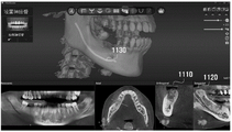
For example, the planning system 100 provides a user interface as in FIG. 9, where the user may place the crown object 910 in the surgical site, angle the crown using the 920 object, and size the crown using the 930 object. Further, the planning system 100 provides a user interface such as 1000 of FIG. 10, where the user can set the dental curve by clicking on the curve of the middle portion of the bone, 1110, 1120 of FIG. 11, and the user can set the neural canal such as 1130 by scrolling the mouse to confirm the neural canal and select it.
Referring again to fig. 3, in step 330, the planning system may develop a dental implant plan.
The planning system 100 may use the processed oral image to set the position and/or orientation of the implant in step 320 to plan implantation. For example, in the example of fig. 12a, the implant planning module 133 may set the angle and size of the crown object 1210 in the CT image and place it at the implant implantation site. Thereafter, the implant planning module 133 can place the implant object 1220 at a predetermined distance from the placed crown object. Furthermore, the size, length, position and implantation angle of the implant object can be set to plan the dental implant operation.
In particular, the planning system 100 may deploy a dental implant object and provide guidance to a practitioner. For example, the planning system 100 can provide guidance so that the implant position is located at a position from the bone to a depth of 0.5 to 1mm, or can provide guidance so that a distance of 2mm or more is secured between the implant position and the root of the adjacent tooth. Further, the planning system 100 provides guidance so as to secure a space of 3mm or more between the implant and the nerve, or provides guidance so as to secure a space of 2mm or more between the implant and the sinus (sinus). Further, the planning system 100 provides guidance in a manner that the implant axis coincides with the center of the denture, or may provide guidance regarding whether there is sufficient bone at the implant implantation site. As another example, the planning system 100 may also provide guidance regarding whether the sleeve is impinging on the teeth, gums, or not. Furthermore, a dental implant implantation can be planned and, as in 1230 of fig. 12b, a dental implant surgery tool, i.e. the insertion direction of the dental handpiece, is set.
In step 340, the planning system 100 may process the pre-guide according to the implant implantation plan, and generate pre-guide processing information to process the pre-guide into a surgical guide associated with the corresponding procedure.
For example, the planning system 100 can be configured to provide a pilot hole area to be etched in the pre-guide using a predetermined range of offset based on a predetermined type, size and/or length of the dental implant socket. Further, the pre-guide is applied with information on the insertion angle and position of the dental implant surgical tool, that is, the dental handpiece, and a flat surface etching area for inserting the upper portion of the pre-guide of the dental handpiece is provided, thereby generating guide processing information. The generated leader process information can be stored in the form of STL & XML files. (step 360)
Thereafter, the planning system 100 may etch the provided etched area in the pre-guide to process the pre-guide into a surgical guide associated with the corresponding procedure. (step 370) more specifically, the planning system includes a milling machine to which machining information of the pre-guide, i.e. information relating to the guide hole area and/or the dental handpiece insertion area, can be generated in the form of a file for guide machining to be applied. The milling machine can machine the pre-guide by referring to the machining file. For example, a milling machine etches the depth, diameter area and dental handpiece insertion area of a pilot hole recorded in a machining file in a corresponding pre-guide to create a surgical guide for dental implant surgery.
For example, in the example of fig. 13a, if the doctor uses the menu as 1310 to apply the offset related to the dental implant socket determined in advance, a pilot hole etching area is set in the planning system, and if the doctor uses the three-dimensional user interface as 1320 to set a flat surface etching area, the doctor uses 1330 to etch the pilot hole and the flat surface in the pre-guide, thereby processing the surgical guide related to the corresponding surgery.
On the other hand, according to an additional embodiment of the present invention, a part of the water injection port region may overlap the guide hole region. The water injection hole region is a region for injecting water into a dental implant operation site in the oral cavity, and has a diameter smaller than that of the guide hole, so that a part of the water injection hole region overlaps with the guide hole region. Further, since the water injection port diameter is smaller than 1/2 of the guide hole diameter, even if a part of the water injection port region overlaps the guide hole region, the guide hole region can be clearly specified. As another example, in case the doctor sets the insertion direction of the dental implant surgery tool, i.e. any dental handpiece, as in fig. 12b, the time zone relating to the flat surface can be set according to the insertion path of any dental handpiece in the planning system, as in 1340 of fig. 13 b.
On the other hand, the dental implant surgery subject may consider the case where the teeth are adjacent. In this case, the first guide hole and the second guide hole are disposed adjacent to each other, but do not overlap. However, a first dental handpiece region for a dental handpiece insertion path associated with the first guide hole and a second dental handpiece region for a dental handpiece insertion path associated with the second guide hole may be formed to overlap. In this case, the first dental handpiece region and the second dental handpiece region can be distinguished in such a way as to have a height difference.
In step 380 of fig. 3, the planning system may visually provide the physician with a CT image of the integrated pre-guide, the crown, and information regarding the type, size, location, and/or orientation of the implant, and report the surgical plan. In this case, the planning system may generate and report information on the bone density, implant implantation position, neural tube distance, and the like of the patient by analyzing the CT image of the patient.
Fig. 5 is a flow chart illustrating a series of steps for planning and processing a surgical plan for any dental implant into a surgical guide associated with a corresponding procedure for the pre-guide of an embodiment of the present invention.
In step 510, a pre-guide set manufactured to a prescribed specification according to the implant implantation site may be prepared. The pre-guide of the present invention may comprise an upper jaw (maxilla) model and a lower jaw (mandible) model depending on the implant implantation site. For example, the pre-guide set of embodiments of the present invention groups the teeth of a person in a prescribed range such that the teeth belong to at least one group, and may be formed as at least one upper jaw model and a lower jaw model for covering the positions of the teeth of the respective group.
The pre-guides of embodiments of the invention may comprise: a guide plate; an impression material such as resin formed inside the guide plate to take an impression inside the oral cavity; and more than one mark formed by the radiation opaque material or the radiation semi-transmissive material.
In step 520, the physician takes an impression of the implant implantation site through the impression material of the pre-guide. That is, the patient holds any model covering the site of the dental implant object and the model of the implant implantation site is made of an impression material, which may be cured by photo-polymerization, for example, in the case where the impression material is a resin.
The model of the patient's mouth taken in the pre-guide is directly included in the surgical guide (step 530), which is finally completed according to an embodiment of the invention by machining the pre-guide (step 520) in a mill, thus serving as a physically integrated unit in the surgical guide for the implant implantation site of the patient. In other words, the model of the implant implantation site is made by the resin for impression included in the pre-guide of the embodiment of the present invention, and thereafter, the surgical guide completed by the processing of the pre-guide also includes the resin for impression for making the model, and thus, even if the pre-guide is a completed product, it can be used as a surgical guide for the corresponding surgery.
In step 530, the pre-guide may be machined according to the dental implant procedure plan.
According to an embodiment of the invention, the pre-guide is manufactured in advance with prescribed specifications, rather than a model manufactured according to the patient's oral morphology. Therefore, information on the specifications of the models of the leader, that is, information on the form, size, image, material, and position of the marker can be stored in the server in advance in the form of the leader library.
Furthermore, the pre-guide library can be integrated with the CT image with the pre-guide mark included in the oral CT image captured with the pre-guide included therein as a reference. The image of the inside of the oral cavity obtained by CT imaging includes information of internal tissues such as a crown (an upper side of a tooth exposed to the outside of a gum), a root (a lower side of a tooth which is a part bonded to an alveolar bone and is hidden by the gum), and an alveolar bone in the oral cavity, and includes a marker image of a pre-guide. In the pre-guide according to an embodiment of the present invention, the marks are formed of a radiopaque substance or a radiopaque substance, and thus recorded in the CT image. Therefore, the marker can be recognized in the CT image, and the marker information is included in the pre-guide library stored in advance, so that the CT image and the pre-guide library can be integrated with the marker as a reference.
Alternatively, the doctor can make a dental implant plan using CT images integrated with the library of pre-guides. For example, in the CT image, the angle and the size of the crown object are set and the crown object is arranged at the implant implantation site, the implant object can be arranged at a predetermined distance from the crown object, and the size, the length, the position, and the implantation angle of the implant object can be set to plan the implant operation.
Thereafter, the server can generate the processing information of the pre-guide piece according to the implant implantation plan, thereby processing the pre-guide piece in the milling machine. For example, the pilot hole area to be etched in the pilot can be set by applying a deviation within a predetermined range based on the type, size and/or length of the dental implant socket, and the pilot can be machined by setting the flat surface etching area on the upper portion of the pilot to be inserted into the dental handpiece by applying the insertion angle and position information of the dental implant surgical tool, i.e., the dental handpiece. The machined pre-guide can then be used as a surgical guide for the corresponding procedure.
The embodiments of the present invention disclosed in the specification and drawings are only intended to illustrate the disclosure of the present invention and to assist understanding of the specific embodiments of the present invention, and do not limit the scope of the present invention. It is apparent to those skilled in the art that various modifications can be implemented according to the technical idea of the present invention in addition to the embodiments disclosed herein.