CN112294376B - A long-range suture locking device of staple and intervention formula for locking suture - Google Patents
A long-range suture locking device of staple and intervention formula for locking suture Download PDFInfo
- Publication number
- CN112294376B CN112294376B CN201910811137.8A CN201910811137A CN112294376B CN 112294376 B CN112294376 B CN 112294376B CN 201910811137 A CN201910811137 A CN 201910811137A CN 112294376 B CN112294376 B CN 112294376B
- Authority
- CN
- China
- Prior art keywords
- locking
- suture
- threading
- nail
- cavity section
- Prior art date
- Legal status (The legal status is an assumption and is not a legal conclusion. Google has not performed a legal analysis and makes no representation as to the accuracy of the status listed.)
- Active
Links
Images


Classifications
-
- A—HUMAN NECESSITIES
- A61—MEDICAL OR VETERINARY SCIENCE; HYGIENE
- A61B—DIAGNOSIS; SURGERY; IDENTIFICATION
- A61B17/00—Surgical instruments, devices or methods
- A61B17/04—Surgical instruments, devices or methods for suturing wounds; Holders or packages for needles or suture materials
- A61B17/0469—Suturing instruments for use in minimally invasive surgery, e.g. endoscopic surgery
-
- A—HUMAN NECESSITIES
- A61—MEDICAL OR VETERINARY SCIENCE; HYGIENE
- A61B—DIAGNOSIS; SURGERY; IDENTIFICATION
- A61B17/00—Surgical instruments, devices or methods
- A61B17/04—Surgical instruments, devices or methods for suturing wounds; Holders or packages for needles or suture materials
- A61B17/0487—Suture clamps, clips or locks, e.g. for replacing suture knots; Instruments for applying or removing suture clamps, clips or locks
-
- A—HUMAN NECESSITIES
- A61—MEDICAL OR VETERINARY SCIENCE; HYGIENE
- A61F—FILTERS IMPLANTABLE INTO BLOOD VESSELS; PROSTHESES; DEVICES PROVIDING PATENCY TO, OR PREVENTING COLLAPSING OF, TUBULAR STRUCTURES OF THE BODY, e.g. STENTS; ORTHOPAEDIC, NURSING OR CONTRACEPTIVE DEVICES; FOMENTATION; TREATMENT OR PROTECTION OF EYES OR EARS; BANDAGES, DRESSINGS OR ABSORBENT PADS; FIRST-AID KITS
- A61F2/00—Filters implantable into blood vessels; Prostheses, i.e. artificial substitutes or replacements for parts of the body; Appliances for connecting them with the body; Devices providing patency to, or preventing collapsing of, tubular structures of the body, e.g. stents
- A61F2/02—Prostheses implantable into the body
- A61F2/24—Heart valves ; Vascular valves, e.g. venous valves; Heart implants, e.g. passive devices for improving the function of the native valve or the heart muscle; Transmyocardial revascularisation [TMR] devices; Valves implantable in the body
-
- A—HUMAN NECESSITIES
- A61—MEDICAL OR VETERINARY SCIENCE; HYGIENE
- A61B—DIAGNOSIS; SURGERY; IDENTIFICATION
- A61B17/00—Surgical instruments, devices or methods
- A61B17/00234—Surgical instruments, devices or methods for minimally invasive surgery
- A61B2017/00238—Type of minimally invasive operation
- A61B2017/00243—Type of minimally invasive operation cardiac
-
- A—HUMAN NECESSITIES
- A61—MEDICAL OR VETERINARY SCIENCE; HYGIENE
- A61B—DIAGNOSIS; SURGERY; IDENTIFICATION
- A61B17/00—Surgical instruments, devices or methods
- A61B17/04—Surgical instruments, devices or methods for suturing wounds; Holders or packages for needles or suture materials
- A61B17/0401—Suture anchors, buttons or pledgets, i.e. means for attaching sutures to bone, cartilage or soft tissue; Instruments for applying or removing suture anchors
- A61B2017/0406—Pledgets
-
- A—HUMAN NECESSITIES
- A61—MEDICAL OR VETERINARY SCIENCE; HYGIENE
- A61B—DIAGNOSIS; SURGERY; IDENTIFICATION
- A61B17/00—Surgical instruments, devices or methods
- A61B17/04—Surgical instruments, devices or methods for suturing wounds; Holders or packages for needles or suture materials
- A61B17/0401—Suture anchors, buttons or pledgets, i.e. means for attaching sutures to bone, cartilage or soft tissue; Instruments for applying or removing suture anchors
- A61B2017/0417—T-fasteners
-
- A—HUMAN NECESSITIES
- A61—MEDICAL OR VETERINARY SCIENCE; HYGIENE
- A61B—DIAGNOSIS; SURGERY; IDENTIFICATION
- A61B17/00—Surgical instruments, devices or methods
- A61B17/04—Surgical instruments, devices or methods for suturing wounds; Holders or packages for needles or suture materials
- A61B17/0401—Suture anchors, buttons or pledgets, i.e. means for attaching sutures to bone, cartilage or soft tissue; Instruments for applying or removing suture anchors
- A61B2017/0464—Suture anchors, buttons or pledgets, i.e. means for attaching sutures to bone, cartilage or soft tissue; Instruments for applying or removing suture anchors for soft tissue
-
- A—HUMAN NECESSITIES
- A61—MEDICAL OR VETERINARY SCIENCE; HYGIENE
- A61B—DIAGNOSIS; SURGERY; IDENTIFICATION
- A61B17/00—Surgical instruments, devices or methods
- A61B17/04—Surgical instruments, devices or methods for suturing wounds; Holders or packages for needles or suture materials
- A61B17/0487—Suture clamps, clips or locks, e.g. for replacing suture knots; Instruments for applying or removing suture clamps, clips or locks
- A61B2017/0488—Instruments for applying suture clamps, clips or locks
-
- A—HUMAN NECESSITIES
- A61—MEDICAL OR VETERINARY SCIENCE; HYGIENE
- A61B—DIAGNOSIS; SURGERY; IDENTIFICATION
- A61B17/00—Surgical instruments, devices or methods
- A61B17/04—Surgical instruments, devices or methods for suturing wounds; Holders or packages for needles or suture materials
- A61B2017/0495—Reinforcements for suture lines
Landscapes
- Health & Medical Sciences (AREA)
- Life Sciences & Earth Sciences (AREA)
- Surgery (AREA)
- Engineering & Computer Science (AREA)
- General Health & Medical Sciences (AREA)
- Biomedical Technology (AREA)
- Heart & Thoracic Surgery (AREA)
- Veterinary Medicine (AREA)
- Public Health (AREA)
- Animal Behavior & Ethology (AREA)
- Nuclear Medicine, Radiotherapy & Molecular Imaging (AREA)
- Medical Informatics (AREA)
- Molecular Biology (AREA)
- Cardiology (AREA)
- Oral & Maxillofacial Surgery (AREA)
- Vascular Medicine (AREA)
- Transplantation (AREA)
- Surgical Instruments (AREA)
- Prostheses (AREA)
Abstract
The invention provides a lock nail for locking a suture, which comprises a locking part, wherein the lock nail is provided with a threading cavity for threading the suture, the threading cavity penetrates through the locking part, the threading cavity comprises a first inner cavity section positioned in the locking part, and the surface roughness of the inner peripheral surface of the first inner cavity section ranges from 0.1 micrometer to 2.5 micrometers. According to the invention, the surface roughness of the inner peripheral surface of the locking part is controlled, so that the locking force of the suture locked in the first inner cavity section of the lock nail is proper, the requirement of the locking force is met, and the suture is prevented from being damaged and broken due to excessive extrusion; and the friction between the suture and the inner peripheral surface of the second inner cavity section is not easy to cause the suture to be worn, thereby preventing the suture from being damaged. The invention also provides an intervention type remote suture locking device using the locking nail.
Description
Technical Field
The invention relates to the technical field of medical instruments, in particular to a locking nail for locking a suture and an intervention type remote suture locking device adopting the locking nail.
Background
The mitral valve is a one-way valve located between the Left Atrium (LA) and the Left Ventricle (LV), and a normal, healthy mitral valve controls the flow of blood from the left atrium to the left ventricle while preventing the flow of blood from the left ventricle to the left atrium. The mitral valve includes a pair of leaflets, called the anterior leaflet and the posterior leaflet, which are in an open state when the left ventricle is in a relaxed state, and blood flows from the left atrium to the left ventricle; when the left ventricle is in a contraction state, the edges of the anterior leaflet and the posterior leaflet are in apposition, and the mitral valve can be completely closed, so that blood is prevented from flowing from the left ventricle to the left atrium. When the leaflets of the mitral valve, or their associated structures, are materially or functionally altered, the anterior and posterior leaflets of the mitral valve coapt poorly, whereby when the left ventricle of the heart contracts, the mitral valve fails to close completely, resulting in blood backflow from the left ventricle to the left atrium, causing a series of pathophysiological changes known as "mitral regurgitation".
In the prior art, the chordae tendineae repair can be realized by implanting one or more sutures into the anterior leaflet and/or the posterior leaflet of the mitral valve respectively, fixing the ends of the sutures on the ventricular wall, apex or papillary muscle, using the sutures as artificial chordae tendineae, or fixing a plurality of sutures on two leaflets together to realize edge-to-edge repair. Commonly used sutures are made of polytetrafluoroethylene (abbreviated as PTFE), expanded polytetrafluoroethylene (abbreviated as e-PTFE), polyethylene terephthalate (abbreviated as PET), polyethylene (abbreviated as PE), polypropylene (abbreviated as PP), etc., and these sutures are suitable for various soft tissue closure and ligation, such as cardiovascular surgery, dentistry, general surgery, and dural repair, etc. Since the suture is fixed and knotted by a doctor, the tightness of the suture is not easy to control in the manual knotting process, thereby affecting the operation effect.
At present, suture locking devices have also appeared which use a locking pin with a hollow internal cavity to fix the suture threaded in the pin by deforming it by pressing it. In the mitral valve repair operation, after an operator implants sutures in the anterior leaflet and/or the posterior leaflet of the mitral valve respectively, the sutures can be fixed on the ventricular wall, papillary muscles or apex of the heart and the like through locking nails to realize 'chordae tendineae repair', and a plurality of groups of sutures can be fixed together through the locking nails to realize 'edge-to-edge' repair. However, after the suture is fixed by the locking nail, the heart always performs a strong contraction motion, so the suture and the locking nail are correspondingly pulled, if the locking force between the locking nail and the suture is insufficient or too large, the suture may be broken, loosened or the locking nail may slide, which not only affects the operation effect, but also may even harm the life of the patient in serious cases.
Disclosure of Invention
The invention aims to solve the technical problem that the invention provides a lock pin for locking suture, which ensures that the locking force of the lock pin is proper by controlling the surface roughness of the inner cavity of the lock pin, and can lock the suture and prevent the suture from being damaged; the invention also provides an intervention type remote suture locking device using the locking nail.
In order to solve the technical problem, the invention firstly provides a lock nail for locking a suture, which comprises a locking part, wherein the lock nail is provided with a threading cavity for threading the suture, the threading cavity penetrates through the locking part, the threading cavity comprises a first inner cavity section positioned on the locking part, and the surface roughness of the inner peripheral surface of the first inner cavity section ranges from 0.1 micrometer to 2.5 micrometers.
The invention also provides an intervention type remote suture locking device which comprises a locking nail and a cartridge assembly, wherein the locking nail comprises a locking part, the locking nail is provided with a threading cavity for threading a suture, the threading cavity penetrates through the locking part, the threading cavity comprises a first inner cavity section positioned in the locking part, the surface roughness range of the inner peripheral surface of the first inner cavity section is 0.1-2.5 micrometers, the locking nail is threaded in the cartridge assembly, and the cartridge assembly presses and holds the locking nail to deform the locking part so as to lock the suture threaded in the threading cavity of the locking nail.
The locking nail adopted by the intervention type remote suture locking device provided by the invention comprises a locking part, and the surface roughness range of the inner peripheral surface of the first inner cavity section of the threading cavity of the locking nail is 0.1-2.5 micrometers. Therefore, the locking force of the suture locked in the first inner cavity section of the lock nail is enabled to be appropriate, the requirement of the locking force is met, and the suture is prevented from being excessively extruded to cause damage and fracture.
Drawings
In order to more clearly illustrate the technical solutions of the embodiments of the present invention, the drawings needed to be used in the embodiments will be briefly described below, and it is obvious that the drawings in the following description are some embodiments of the present invention, and it is obvious for those skilled in the art to obtain other drawings based on these drawings without creative efforts.
Fig. 1 is a schematic perspective view of an interventional remote suture locking device according to an embodiment of the present invention.
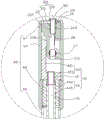
Fig. 2 is a sectional view taken along line II-II in fig. 1.
Fig. 3 is a perspective view of a staple employed in the interposed remote suture locking device of fig. 1.
Fig. 4 is a sectional view taken along line IV-IV in fig. 3.
Fig. 5 is a cross-sectional view taken along line V-V of fig. 3.
Fig. 6 is an enlarged view of a VI portion in fig. 2.
Fig. 7 is a schematic view of the lock pin of fig. 3 with a suture threaded therethrough.
FIG. 8 is a schematic view of the staple of FIG. 7 in a deformed locking suture position.
Fig. 9 is a sectional view taken along line IX-IX in fig. 8.
Fig. 10-12 are schematic views of an interventional remote suture locking device for an edge-to-edge repair process of a diseased mitral valve according to an embodiment of the present invention.
Fig. 13-14 are schematic views of the process of using the intervention remote suture locking device provided by one embodiment of the invention to fix the suture in the lock pin.
Fig. 15 is an enlarged view of the XV portion in fig. 12.
FIG. 16 is a statistical chart of the results of the surface roughness test, deformation rate test, locking force test and fatigue test of the lock pin of the present invention and the lock pin of the comparative example.
Detailed Description
The technical solutions in the embodiments of the present invention will be clearly and completely described below with reference to the drawings in the embodiments of the present invention, and it is obvious that the described embodiments are only a part of the embodiments of the present invention, and not all of the embodiments. All other embodiments, which can be derived by a person skilled in the art from the embodiments given herein without any inventive step, are within the scope of the present invention.
Furthermore, the following description of the various embodiments refers to the accompanying drawings, which illustrate specific embodiments in which the invention may be practiced. Directional phrases used in this disclosure, such as, for example, "upper," "lower," "front," "rear," "left," "right," "inner," "outer," "side," and the like, refer only to the orientation of the appended drawings and are, therefore, used herein for better and clearer illustration and understanding of the invention, and do not indicate or imply that the device or element so referred to must have a particular orientation, be constructed and operated in a particular orientation, and are therefore not to be considered limiting of the invention.
Orientation definition: for clarity of description, the end of the surgical procedure that is closer to the operator will be referred to hereinafter as the "proximal end" and the end that is further from the operator will be referred to hereinafter as the "distal end"; the axial direction is parallel to the direction of the connection line of the center of the far end and the center of the near end of the medical instrument; the foregoing definitions are for convenience only and are not to be construed as limiting the present invention.
Referring to fig. 1 to 6, the present invention provides an intervention type remote suture locking device 100 for fixing a suture and a locking nail 300, wherein the intervention type remote suture locking device 100 includes a collet assembly 20, a driving assembly 40 disposed at a proximal end of the collet assembly 20, and a pushing assembly 60 sleeved outside the collet assembly 20 and the driving assembly 40. The distal end of the cartridge assembly 20 is provided with a space 25 for placing the locking nail 300, the locking nail 300 is provided with a threading cavity 301 along the axial direction, and the intervention type remote suture locking device 100 axially opens a threading channel 26 passing through the cartridge assembly 20 and the driving assembly 40. The locking nail 300 comprises a locking part 310 and a retaining part 330 arranged at the far end of the locking part 310, and the threading cavity 301 penetrates through the locking part 310 and the retaining part 330. The locking portion 310 is received in the gap 25 of the collet assembly 20, and the retaining portion 330 is stopped at the distal end surface of the pushing assembly 60. The threading cavity 301 includes a first cavity section 302 located at the locking portion 310 and a second cavity section 304 located at the holding portion 330, and the surface roughness of the inner circumferential surface of the first cavity section 302 is greater than or equal to the surface roughness of the inner circumferential surface of the second cavity section 304. The suture is threaded through the threading cavity 301 and the threading channel 26 of the locking nail 300, and the driving component 40 rotates relative to the pushing component 60 and moves axially to push against the chuck component 20, so as to press the locking nail 300 placed in the gap 25, and the locking nail 300 is deformed to fix the suture. Because the surface roughness of the inner peripheral surface of the first inner cavity section 302 of the threading cavity 301 of the lock nail 300 is larger than the surface roughness of the inner peripheral surface of the second inner cavity section 304, the locking force of the suture locked in the first inner cavity section 302 of the lock nail 300 can be higher, and the friction between the suture and the inner peripheral surface of the second inner cavity section 304 is not easy to wear the suture, thereby preventing the suture from being damaged.
The interventional remote suture locking device 100 also includes a handle 80 connected to the proximal end of the drive assembly 40 and the proximal end of the pusher assembly 60. The handle 80 includes a fixed portion 82 located at the distal end and a movable portion 84 located at the proximal end and capable of moving relative to the fixed portion 82, the fixed portion 82 is fixedly connected to the proximal end of the pushing assembly 60, the movable portion 84 is connected to the proximal end of the driving assembly 40, and the driving assembly 40 is driven to move axially relative to the pushing assembly 60 by the relative movement between the movable portion 84 and the fixed portion 82. Specifically, the movable portion 84 and the fixed portion 82 can rotate and move axially relative to each other, so as to drive the driving assembly 40 to rotate and move axially relative to the pushing assembly 60, and when the driving assembly 40 moves axially and distally to push against the chuck assembly 20, the locking pin 300 placed in the gap 25 can be pressed, so as to complete the fixation of the suture and the locking pin 300.
The locking pin 300 is made of a biocompatible material such as stainless steel, pure titanium, nickel titanium, cobalt chromium alloy, and preferably pure titanium or stainless steel.
Referring to fig. 3-5, threading cavities 301 of the locking nail 300 are axially disposed through opposite ends of the locking nail 300, and the threading cavities 301 are adapted to receive and pass a suture. Locking portion 310 may be collapsed when subjected to a mechanical external force to secure the suture in threading lumen 301 of staple 300. The cross section of the threading cavity 301 of the locking portion 310 may be various shapes, for example, a cylindrical shape, a prismatic shape, an elliptical shape, a polygonal shape, or an irregular shape, as long as there is a threading cavity 301 for accommodating a suture. The proximal face edge of the locking portion 310 is rounded and the rounded surface is smooth, i.e. less rough, to avoid tissue damage to the proximal face of the locking portion 310.
In other embodiments, two opposite positions of the inner peripheral surface of the first cavity section 302 are respectively provided with a convex locking platform and a concave locking groove, and when the locking nail 300 is subjected to external clamping force, the locking part 310 is deformed, so that the locking platforms are pressed into the corresponding locking grooves. As the lock pin 300 continues to deform, the locking platform and the locking groove simultaneously deform until they cannot be separated, at which point the suture 500 is securely held in the threading lumen 301 of the lock pin 300.
The first inner cavity section 302 is the main area of the locking suture of the locking nail 300, and the inner surface of the first inner cavity section 302 of the locking nail 300 is in direct contact with the suture, so the surface roughness of the inner peripheral surface of the first inner cavity section 302 directly affects the locking force of the locking nail. Surface roughness refers to the small pitch and small peak-to-valley unevenness that the machined surface of the material has. The smaller the surface roughness, the smoother the surface of the material. Surface roughness is typically caused by the machining method used, surface treatment and other factors, such as friction between the tool and the surface of the part during machining, plastic deformation of the surface layer metal during chip separation, and high frequency vibrations in the process system. Methods of surface treatment include physical polishing, chemical polishing, electroplating, sand blasting, spraying, electrical discharge machining, and the like. Because of the difference between the processing method and the surface treatment method, the depth, density, shape and texture of the trace left on the processed surface are different. The surface roughness of the inner surface of the first lumen segment 302 affects the locking pin 300 primarily in the following ways:
first, the locking force of the locking pin 300 is affected, and particularly, the effect of the surface roughness on the locking force is mainly reflected in the stability of the fit of the first cavity section 302 of the locking pin 300. After the locking nail 300 penetrates through a suture line and is deformed under pressure, the inner cavities of the locking parts 310 of the locking nail 300 are in clearance fit, the rougher the surfaces of the inner cavities are, the more easily the inner cavities are worn, the gap is gradually increased and the connection strength is gradually reduced along with the continuous movement of human tissues after the suture line is locked; the inner circumferential surface of the locking part 310 of the locking nail 300 is in interference fit with the suture, and the microcosmic peaks of the locking part 310 are squeezed out when the locking nail is pressed, so that the actual effective interference is reduced, and the connection strength is reduced.
Secondly, the fatigue strength of the locking nail 300 is affected because the rough surface has larger wave troughs and is sensitive to stress concentration, so that the surface with larger roughness has smaller effective contact area between the matching surfaces, larger pressure intensity, larger frictional resistance, faster abrasion and poorer abrasion resistance; the rougher surface tends to allow blood to penetrate into the inner layer of the nail 300 through the microscopic valleys of the surface, resulting in surface corrosion.
Thus, the surface roughness of the inner circumferential surface of the first lumen segment 302 can be adjusted according to the locking force required for the suture 500. In order to ensure the balance between the locking force and the fatigue strength and the safety and effectiveness of the locking pin 300, the surface roughness of the inner circumferential surface of the first cavity section 302 ranges from 0.1 micron to 2.5 microns.
Referring to fig. 7-9, after the suture 500 is threaded through the threading cavity 301 of the lock pin 300, the cartridge assembly 20 compresses the lock pin 300 to deform the lock pin 300 to secure the suture. Therefore, the deformation rate of the lock pin 300 affects the locking force and fatigue resistance of the lock pin 300. The deformation rate of the pin 300 reflects the degree of deformation of the pin 300 after being gripped. In the present invention, when the locking portion 310 of the locking nail 300 is pressed, the thickness of the minor axis of the cross section of the threading cavity 301 of the locking portion 310 for fixing the suture 500 at the minimum dimension in the direction perpendicular to the axial direction of the threading cavity 301 is H, the thickness of the single-sided wall in the initial state of the locking nail 300 is T1, and the deformation rate ∈ of the locking nail 300 is 2W/H × 100%. The deformation rate epsilon can reflect the size of the internal clearance of the threading cavity 301 after the locking nail 300 is pressed and deformed. If the deformation rate of the lock pin 300 is larger, the H value is smaller, which indicates that the clearance after the deformation of the lock pin 300 is smaller and the locking force is higher. However, if the deformation ratio is too large, the gap after the deformation of the lock pin 300 is too small, which may cause the suture 500 to be broken or affect the fatigue resistance of the lock pin 300. In the present invention, the deformation rate of the locking part 310 ranges from 50% to 90%, thereby securing the locking force of the locking pin 300.
The e-PTFE suture is a common surgical suture, is chemically synthesized by 100 percent of polytetrafluoroethylene, is a single-strand non-absorbable surgical suture, and has the characteristics of high porosity, high smoothness, low friction coefficient and the like. In the manual knotting process of the e-PTFE suture, the e-PTFE suture can be knotted normally only by more than two circles, and when the suture is fixed by adopting a metal lock pin, the locking force is required to be proper, so that the slippage caused by insufficient locking force is avoided; however, because the e-PTFE suture is a single-strand wire, the wear resistance of the e-PTFE suture is relatively poor, and therefore, the fracture of the suture caused by excessive locking force needs to be avoided, and the fatigue resistance of the lock pin is ensured when the suture and the lock pin are repeatedly pulled under the condition that the heart continuously beats after the lock pin is combined with the e-PTFE suture. In the present embodiment, the deformation ratio is preferably in the range of 55% to 80%, and the surface roughness of the inner peripheral surface of the locking portion 310 is matched with the deformation ratio of the locking portion 310, so that the balance between the locking force and the fatigue strength is achieved, and the locking device is particularly suitable for locking and fixing a single suture such as an e-PTFE suture. In other embodiments, the deformation ratio is further preferably in the range of 60-75%, and is particularly suitable for locking 2-6 e-PTFE sutures.
The retaining part 330 is disposed at the distal end of the locking part 310, specifically, the retaining part 330 is at least partially protruded from the distal outer wall of the locking part 310 in the radial direction, that is, the outer diameter of the retaining part 330 is larger than the outer diameter of the locking part 310, that is, the cross-sectional area of the distal end surface of the retaining part 330 is larger than the cross-sectional area of the locking part 310 in the radial direction. Thus, the retaining portion 330 acts as a stop to prevent the distal surface of the locking pin 300 from being deformed by being crushed and pulled or slid into the void 25 of the cartridge assembly 20. In this embodiment, the holding portion 330 is a boss having an annular cross section. In the prior art, the distal end of the locking pin 300 is not provided with the retaining portion 330, and when the distal end surface of the locking pin 300 is deformed by being compressed and easily pulled or slid into the gap 25 of the cartridge assembly 20, the distal end surface of the locking pin 300 may be caught by the cartridge assembly 20 when the cartridge assembly 20 is opened and restored to the original position, and the locking pin 300 cannot be automatically separated from the distal end of the interventional remote suture locking device 100.
The holder 330 has a second lumen segment 304 in communication with the first lumen segment 302, i.e. the second lumen segment 304 and the first lumen segment 301 form a threading lumen for threading a suture. The surface roughness of the inner circumferential surface of the second cavity section 304 is less than or equal to the surface roughness of the inner circumferential surface of the first cavity section 302, so that the friction force between the suture and the inner circumferential surface of the second cavity section 304 is reduced, and the suture is prevented from being damaged by long-term friction.
The outer peripheral edge of the distal end and the outer peripheral edge of the proximal end of the holding portion 330 are both provided with round corners, and the outer surface of the holding portion 330 is an arc surface to prevent the locking nail 300 from scratching the internal tissues of the patient body. In this embodiment, the holding portion 330 is a boss with an annular cross section, and the outer surface of the boss is an arc surface. The intersection of the distal end face of the boss and the inner circumferential surface of the second lumen section 304 is provided with a fillet.
The intersection of the distal end surface of the holding part 330 and the inner circumferential surface of the first lumen segment 302 is provided with a first smooth transition area 305, and the suture locked in the threading lumen 301 of the locking nail 300 contacts with the first smooth transition area 305 at a certain inclination angle, so as to avoid cutting the suture at the intersection of the distal end surface of the holding part 330 and the inner circumferential surface of the first lumen segment 302, and avoid friction fatigue and even breakage of the suture. In this embodiment, the first rounded transition area 305 is formed by electro-discharge machining, and has a surface roughness in the range of 0.1 to 2.5 microns to avoid damage to the stitches. In other embodiments, the first rounded transition area 305 may be electro-discharge machined and then subjected to a coating process to further reduce the roughness, wherein the surface roughness of the PTFE coating is in the range of 0.1 micron to 0.5 micron.
As shown in fig. 4, a second rounded transition region 306 is disposed between the first rounded transition region 305 and the inner circumferential surface of the first lumen section 302, the second rounded transition region 306 having a surface roughness of less than 2 microns. If the surface roughness of the second smooth transition region 306 is too large, friction fatigue may be generated to the suture and cause the suture to break, and the surface roughness of the second smooth transition region 306 is controlled within 2 microns, which can effectively avoid the suture from breaking.
To reduce the roughness of the second rounded transition region 306, electrical discharge machining may be applied to the second rounded transition region 306; to further reduce the roughness of the second rounded transition region 306, a PTFE film plating process may be added on the basis of the electrical discharge machining.
To further reduce the roughness or the offset of the second rounded transition region 306, the second rounded transition region 306 is a tapered surface with a decreasing inner diameter from the distal end to the proximal end, and the single-sided slope of the tapered surface is in the range of 0.3 degrees to 0.8 degrees, preferably 0.5 degrees to 0.6 degrees.
Referring to fig. 4 and 5, the size of the inner hole D1 of the threading cavity 301 of the locking nail 300 is determined according to the diameter and the number of sutures to be locked, and the inner hole D1 of the threading cavity 301 ranges from 0.8 micron to 1.2 microns. The currently used e-PTFE sutures have an outer diameter of 0.3 micron and the number of locks required is 2 to 4, preferably the inner bore D1 of the threading lumen 301 ranges from 0.85 micron to 1.0 micron. The wall thickness T1 of the locking portion 310 of the locking pin 300 is in the range of 0.1 micron to 0.2 micron, the wall thickness T1 of the locking portion 310 being less than 0.1 micron is not good for the fatigue resistance of the locking pin 300, and the wall thickness T1 of the locking portion 310 being more than 0.2 micron is not good for the deformation and locking strength of the locking pin 300; preferably, the wall thickness T1 of the locking portion 310 ranges from 0.12 microns to 0.18 microns.
The boss thickness T2 of the retention portion 330 ranges from 0.3 microns to 0.6 microns; preferably, the boss thickness T2 of the retention portion 330 is in the range of 0.4 microns to 0.5 microns. The boss outer diameter D2 of the holder 330 ranges from 1.6 microns to 2.2 microns; preferably, the boss outer diameter D2 of the holder 330 is in the range of 1.8 microns to 2.0 microns. The overall length L of the locking pin 300 ranges in size from 4 microns to 6.5 microns; the overlong overall length L of the locking nail 300 is not only unfavorable for delivery, but also affects the safety of the locking nail 300 implanted into a human body, and preferably, the overall length L of the locking nail 300 has a length size ranging from 4.5 micrometers to 6.0 micrometers. The overall length L of the pin 300 minus the boss thickness T2 of the retaining portion 330 is the length of the first lumen segment 302.
Referring to fig. 2 and 6, the jaw assembly 20 includes a first jaw 22 and a second jaw 24 connected to or integrally formed with each other, wherein the connection between the first jaw 22 and the second jaw 24 is connected to a threading channel 26. A gap 25 is formed between the distal end of the first cartridge 22 and the distal end of the second cartridge 24, and a locking pin 300 is placed in the gap 25, i.e., the locking pin 300 is inserted into the cartridge assembly 20. When the driving assembly 40 rotates relative to the pushing assembly 60 and moves axially to push the first chuck 22 and the second chuck 24 of the chuck assembly 20 to rotate towards each other, the first chuck 22 and the second chuck 24 can press the locking nail 300, so that the locking nail 300 is deformed to lock the suture passing through the threading cavity 301 of the locking nail 300.
In this embodiment, the proximal end of the first clamping head 22 is rotatably connected to the proximal end of the second clamping head 24 by a shaft 27, and the shaft 27 defines a through hole 271 communicating with the threading channel 26. The side of first jaw 22 facing away from second jaw 24 is provided with a sloped slide guide surface 226, and slide guide surface 226 is located at the distal end of first jaw 22 and extends obliquely towards the side facing away from threading channel 26. The side of first jaw 22 facing second jaw 24 adjacent the distal end is provided with first clamping teeth 227, first clamping teeth 227 including a plurality of gullets each extending in an axial direction generally parallel to axial bore 224. The side of the second jaw 24 facing the first jaw 22 adjacent the distal end is provided with second clamping teeth 243, the second clamping teeth 243 comprise a plurality of teeth slots, and each tooth slot of the second clamping teeth 243 extends in the same direction as the tooth slot of the first clamping teeth 227. When the first chuck 22 and the second chuck 24 are rotatably connected by the rotating shaft 27, the first teeth 227 of the first chuck 22 and the second teeth 243 of the second chuck 24 are dislocated and can be engaged with each other, so that the first chuck 22 rotates towards the second chuck 24, and the first teeth 227 and the second teeth 243 extrude the locking pin 300 placed in the gap 25 into a shape with curvature. The collet assembly 20 further includes a resilient member 28, wherein the resilient member 28 is used for rotational restoration of the first collet 22 and/or the second collet 24 to facilitate the insertion of the locking pin 300 into the gap 25 between the first collet 22 and the second collet 24, and after the first collet 22 and the second collet 24 compress the locking pin 300, the first collet 22 is restored to facilitate the smooth release of the locking pin 300.
The driving member 44 includes a screw 442 and a rotating shaft 445 axially connected to the screw 442, specifically, a distal end of the rotating shaft 445 is fixedly connected to the screw 442, a proximal end of the rotating shaft 445 is fixedly connected to the movable portion 84, and the rotation of the movable portion 84 can drive the rotating shaft 445 and the screw 442 to rotate together.
The push rod member 42 includes a push rod 421 for abutting against the slide guide surface 226 of the first chuck 22 in an axial sliding manner, and a connecting block 423 disposed at a proximal end of the push rod 421, wherein the push rod 421 is located at one side of the connecting block 423 in a radial direction. The connecting block 423 is provided with a through hole along the axial direction, the through hole penetrates through the far end face and the near end face of the connecting block 423, and the connecting rod pin 45 is rotatably inserted into the through hole. The pushing assembly 60 includes a thrust tube 62 rotatably sleeved on the screw 442, a front end outer tube 64 connected to a distal end of the thrust tube 62, a pushing shaft 66 connected to a distal end of the thrust tube 62, and an end cap 67 covering a distal end of the front end outer tube 64. The thrust pipe 62 is provided with an internal thread corresponding to the screw rod 442, and the rotation of the rotary mandrel 445 drives the screw rod 442 to rotate relative to the thrust pipe 62 and move along the axial direction; preferably, the inner wall of the thrust tube 62 is provided with an internal thread 622 corresponding to the screw 442, the distal end of the pushing shaft 66 is fixedly connected to the proximal end of the thrust tube 62, and the proximal end of the pushing shaft 66 is fixedly connected to the fixing portion 82.
Referring to fig. 10 to 15, the use of the interventional remote suture locking device 100 and the locking nail 300 in mitral valve edge-to-edge repair is described below by taking a mitral valve repair of a heart as an example.
The first step is as follows: as shown in fig. 10, firstly, after the femoral vein puncture and transseptal puncture of a patient, a plurality of sutures 500 with elastic gaskets 501 are respectively implanted into the anterior leaflet 401 and the posterior leaflet 403 of the mitral valve, and the point contact between the sutures 500 and the valve leaflets is converted into the surface contact between the elastic gaskets 501 and the valve leaflets, so that the risk of tearing of the valve leaflets can be effectively reduced;
the second step is that: as shown in fig. 11 and 13, a plurality of sutures 500 on the two side leaflets are all threaded into the threading cavity 301 of the locking nail 300 outside the patient body, and the proximal ends of the sutures 500 pass through the threading cavity 301 of the locking nail 300 of the intervention type remote suture locking device 100, the gap between the first clamping head 22 and the second clamping head 24, the through hole 271 of the rotating shaft 27, the through hole of the front end outer tube 64, the lead hole of the connecting rod pin 45 and the hollow inner hole of the rotating shaft 445 in sequence and then pass out from the proximal end of the movable part 84;
the third step: pushing the distal end of the interventional remote suture locking device 100 into the heart through the femoral vein and interatrial septum by means of a bending sheath (not shown), moving closer towards the leaflets of the mitral valve while pulling the suture 500 until the distal end of the interventional remote suture locking device 100 reaches a predetermined position;
the fourth step: adjusting the tightness of the sutures 500 on the anterior leaflet 401 and the posterior leaflet 403, respectively, while determining by ultrasound the state of minimum mitral regurgitation, when this state is reached, stopping the adjustment, maintaining the tightness of the two sets of sutures 500, i.e. maintaining the relative distance between the anterior leaflet 401 and the posterior leaflet 403 of the mitral valve;
the fifth step: as shown in fig. 11 and 14, the fixed portion 82 of the handle 80 is kept stationary, the movable portion 84 is driven to rotate distally, at this time, the rotating mandrel 445 drives the screw rod 442 to move distally relative to the pushing shaft 66, the screw rod 442 drives the ejector rod 42 to move distally, the distal end of the ejector rod 421 of the ejector rod 42 continuously presses the first chuck 22, so that the first chuck 22 approaches the second chuck 24, the locking nail 300 between the first chuck 22 and the second chuck 24 is pressed, the elastic member 28 is pressed to elastically deform until the locking nail 300 deforms, the locking nail 300 and the suture 500 threaded in the threading cavity 301 of the locking nail 300 are fixed together, and the retaining portion 330 is stopped outside the end cap 67; then, the movable part 84 is driven to move towards the proximal end, the push rod 421 releases the extrusion on the first chuck 22, the first chuck 22 is opened and restored to the initial position under the elastic resetting action of the elastic element 28, and the deformed locking nail 300 is released from the gap between the first chuck 22 and the second chuck 24; at this point, suture 500 is locked within first lumen segment 302 of deformed locking portion 310 such that the locking force of suture 500 is higher; in addition, the suture 500 contacts with the first and second smooth transition regions 305 and 306 of the locking nail 300, and the surface roughness of the first and second smooth transition regions 305 and 306 is small, so that the damage of the suture 500 can be avoided.
And a sixth step: as shown in fig. 12 and 15, the distal end of the interventional remote suture locking device 100 is withdrawn from the patient, the locking nail 300 is left in the patient, the suture 500 at the end of the locking nail 300 is cut off, and at this time, the locking nail 300 fixes the two groups of the suture 500 which respectively pass through the anterior leaflet 401 and the posterior leaflet 403 together, and the anterior leaflet 401 and the posterior leaflet 403 of the mitral valve form a diplopore structure, thereby completing the edge-to-edge repair.
It is understood that the above description only illustrates the use of the present invention in the case of an interventional remote suture locking device for interventional mitral valve repair procedure via the femoral vein-interatrial septum-left atrium-mitral valve approach, and that the present invention may also be used for locking and securing sutures in other surgical procedures.
The interventional remote suture knot device 100 of the present invention is particularly useful in the following scenarios, such as:
(1) performing an interventional mitral valve repair procedure via a femoral vein-interatrial septum-left atrium-mitral valve pathway;
(2) performing an interventional mitral valve repair procedure via a femoral artery-aortic arch-aortic valve-left ventricle-mitral valve pathway;
(3) interventional mitral valve repair procedures are performed via the jugular vein-interatrial septum-left atrium-mitral valve approach.
The following scenario applies as well: (1) performing an interventional tricuspid valve repair procedure via the femoral vein-right atrium-tricuspid valve pathway; (2) interventional tricuspid valve repair surgery is performed via the jugular vein-right atrium-tricuspid valve approach. Remotely operating the interventional remote suture locking device 100 outside the patient's body secures a suture 500 implanted on the leaflets with the locking staples 300 by way of minimally invasive intervention.
The lock pin in the other embodiments is similar in structure to the lock pin 300 in embodiment 1, except that: after the manufacturing of the locking pin, the inner circumferential surface of the first cavity section of the locking pin is subjected to mirror discharge treatment or linear cutting treatment, so that the surface roughness of the inner circumferential surface of the first cavity section is different from the surface roughness of the inner circumferential surface of the first cavity section 302 in embodiment 1, and the locking pins of embodiments 2 to 9 are obtained, respectively, as shown in fig. 16.
The same process was used to prepare a nail having the same size and structure as the nail 300 of example 1, and the surface roughness of the inner circumferential surface of the nail was adjusted to different ranges by mirror discharge treatment or wire cutting treatment, as the nails of comparative examples 1 to 16, as shown in fig. 16.
The surface roughness test, the deformation rate test, the locking force test and the fatigue test were performed on the lock pins of examples 1 to 9 and comparative examples 1 to 16, respectively, and the results are shown in fig. 16.
Surface roughness test
The principle of the contact pin method test is as follows: when the contact pin slides lightly along the measured surface, the contact pin also moves up and down along the peak valley when sliding due to the tiny peak valley of the surface, and the motion condition of the contact pin reflects the condition of the surface profile.
And (4) testing standard: GB/T1031 and GB/T10610.
Testing an instrument: dektak 6M Probe profilometer, Bruker, USA.
Testing parameters: probe pressure: 10 mg; sliding distance: 800 microns; the sliding time is as follows: 8 seconds, glide speed 100 microns/second.
The test method comprises the following steps: the locking pin 300 of examples 1 to 9 and comparative examples 1 to 16 was cut in half along the axis and divided into two symmetrical parts, 3 to 10 points were respectively taken at the first cavity section 302 of each part, the change of the surface profile was measured during the process that a probe with a pressure of 10mg was slid at a speed of 100 μm/sec for 800 μm at each sampling point, and the average value of the test results of all the sampling points of the two parts was taken as the surface roughness of the inner peripheral surface of the locking pin 300.
Deformation rate test
The test method comprises the following steps: firstly, measuring the outer diameter of the locking nail 300 by a micrometer, measuring the inner diameter of the locking nail 300 by a needle gauge, and subtracting the inner diameter from the outer diameter to obtain the bilateral wall thickness, so as to respectively obtain the bilateral wall thickness 2T1 of the locking nails 300 of the embodiments 1-9 and the comparative examples 1-16 in the initial state; then, the intervention type suture locking device 100 is adopted, and the locking nails 300 of the embodiments 1 to 9 and the comparative examples 1 to 16 are respectively used for locking two U-shaped folded e-PTFE sutures 500; the thickness H of the short axis of the cross section of the locking portion 310 of the locked locking pin 300 at the minimum dimension in the direction perpendicular to the axial direction of the first cavity section 302 is measured by an optical image measuring instrument, namely VMS322, produced by shenzhen zhitai precision instruments ltd, and then the deformation rate of the locking pin is calculated from ∈ 2W/hx 100%, and the result is shown in fig. 16.
Test of locking force
The test method comprises the following steps: in the deformation rate test, the locking force test is performed on the locked lock pin 300 and the locked suture 500. The test equipment is an HY-0580 electronic type universal tensile tester produced by Shanghai Heifeng precision instruments Co. The test procedure was as follows: the locked sample is provided with two closed coils, one coil is used as a fixed end and fixed on a drag hook at the fixed end of the tensile testing machine, the other coil penetrates into a drag hook at the movable end of the tensile testing machine, and the moving speed of the movable end of the tensile testing machine is set to be 100 micrometers/min. And recording the maximum value of the pulled-off or pulled-off suture collected by the tensile testing machine as the locking force of the lock pin. According to the related literature, when the locking force is 3N, the tensile force requirement clinically on the suture can be satisfied.
Fatigue test
The purpose of the fatigue test is to verify that the locking pin 300 after locking the suture 500 is satisfactory for 10 year load use as a medical device implant. Before testing, the two U-shaped folded e-PTFE sutures 500 are locked by the lock pin 300, and then the lock pin 300 and the sutures 500 are placed in a fatigue testing machine simulating the beating of the left heart system of a human heart to carry out nondestructive fatigue testing. The fatigue testing equipment is an AWT-1000 type artificial heart valve fatigue resistance testing machine of Shanghai heart valve testing equipment Limited. The test was carried out according to the method for "fatigue test" in ISO 5840 and GB 12279-2008 "cardiovascular implant prosthetic heart valve", cycle: the number of times is more than or equal to 4 hundred million, the sliding of the locking nail 300 caused by load in the fatigue test period and the damage condition of the locking nail 300 to the suture 500 are recorded, and whether the requirements related to ISO 5840 and GB 12279-2008 heart valve prosthesis by cardiovascular implant are met is verified.
From the test results shown in fig. 16, it can be seen that:
1) when the surface roughness of the first cavity section 302 of the locking pin 300 is the same, the deformation rate of the locking pin 300 is increased, and the locking force is increased; when the deformation rate of the locking pin 300 is the same, the surface roughness of the first cavity section 302 increases, and the locking force increases accordingly.
2) When the roughness of the first cavity section 302 of the locking nail 300 is less than 0.10 microns, the locking force value is small, the fatigue test fails due to the slippage of the suture 500, and the requirement of fatigue performance cannot be met.
3) When the roughness of the first cavity section 302 of the locking nail 300 is larger than 2.5 microns, the locking force value is too large, the suture 500 is worn out to cause failure of the fatigue test, and the requirement of fatigue performance cannot be met.
4) When the deformation rate of the lock pin 300 is less than 0.50, the deformed lock pin 300 has a large gap and a small locking force, and cannot effectively lock the suture 500 and meet the requirement of fatigue performance.
5) When the deformation rate of the lock pin 300 is greater than 0.90, the lock pin 300 easily crushes the suture 500, the locking force value of the lock pin 300 is in a downward trend, and the requirement of fatigue performance cannot be met.
It can be seen that, in fig. 16, embodiments 1 to 9 satisfy the requirements of better locking capability and fatigue resistance, specifically, the surface roughness of the inner circumferential surface of the first cavity section 302 of the locking nail 300 of the present invention is in the range of 0.1 to 0.25 μm; the deformation rate of the locking part 310 of the lock nail 300 is in the range of 50% -90%, and when the two are matched, the locking part 310 has proper locking force and fatigue resistance to two e-PTFE sutures 500 which are folded in U shape and are arranged in the lock nail 300 in a penetrating way. The lock pins in comparative example 1 to comparative example 16 in fig. 16 did not satisfy the requirement of fatigue property.
The foregoing is illustrative of embodiments of the present invention, and it should be noted that modifications and adaptations to those skilled in the art may be made without departing from the principles of the embodiments of the present invention and are intended to be within the scope of the present invention.
Claims (14)
1. A locking nail for locking a suture, the locking nail comprising a locking portion, the locking nail having a threading cavity for threading a suture, the threading cavity passing through the locking portion, characterized in that the threading cavity comprises a first cavity section at the locking portion, an inner circumferential surface of the first cavity section having a surface roughness in the range of 0.1 micrometer to 2.5 micrometers; the locking nail further comprises a retaining part arranged at the far end of the locking part, the threading cavity further comprises a second inner cavity section penetrating through the retaining part, the second inner cavity section is communicated with the first inner cavity section, and the surface roughness of the inner circumferential surface of the second inner cavity section is smaller than or equal to that of the inner circumferential surface of the first inner cavity section.
2. The lock pin according to claim 1, wherein a deformation ratio of the locking portion ranges from 50% to 90%.
3. The lock pin according to claim 1, wherein a deformation ratio of the lock portion ranges from 60% to 75%.
4. The locking pin of claim 1 wherein the threading lumen has an inner diameter in the range of 0.8 microns to 1.2 microns and the locking portion has a wall thickness in the range of 0.1 microns to 0.2 microns.
5. The locking nail according to claim 1, wherein the first cavity section is provided with a convex locking platform and a concave locking groove on two opposite sides of the inner circumferential surface, and when the locking nail is subjected to external pressure, the locking part is deformed to press the locking platform into the locking groove.
6. The locking nail of claim 1 wherein the retaining portion projects radially at least partially from a distal outer wall of the locking portion.
7. The locking nail according to claim 1, wherein the distal peripheral edge and the proximal peripheral edge of the retaining portion are rounded, and the outer surface of the retaining portion is a curved surface.
8. The locking nail according to claim 1, wherein the intersection of the distal end face of the retaining portion and the inner circumferential surface of the first lumen segment is provided with a first rounded transition zone.
9. The locking nail according to claim 8, wherein the first rounded transition zone has a surface roughness in the range of 0.1-2.5 microns.
10. The locking nail according to claim 8, wherein a second rounded transition region is provided between the first rounded transition region and the inner circumferential surface of the first cavity section, the second rounded transition region having a surface roughness of less than 2 microns.
11. The locking pin according to claim 10, wherein said second rounded transition region is a tapered surface with a decreasing inner diameter from the distal end to the proximal end, said tapered surface having a single edge slope in the range of 0.3 degrees to 0.8 degrees.
12. The locking nail according to claim 1, wherein the retaining portion has an outer diameter in the range of 1.6-2.2 microns and a wall thickness in the range of 0.3-0.6 microns.
13. An interventional remote suture tying device comprising the lock pin of any one of claims 1 to 12, further comprising a cartridge assembly into which the lock pin is threaded, the cartridge assembly pressing and gripping the lock pin to deform the locking portion to lock a suture threaded into the threading lumen of the lock pin.
14. The interventional remote suture locking device of claim 13, further comprising a driving assembly and a pushing assembly disposed at a proximal end of the cartridge assembly, the pushing assembly configured to push the cartridge assembly and the driving assembly, the driving assembly configured to drive the cartridge assembly to crimp the locking pin.
Priority Applications (4)
| Application Number | Priority Date | Filing Date | Title |
|---|---|---|---|
| CN201910811137.8A CN112294376B (en) | 2019-08-29 | 2019-08-29 | A long-range suture locking device of staple and intervention formula for locking suture |
| PCT/CN2020/107994 WO2021036761A1 (en) | 2019-08-29 | 2020-08-07 | Locking nail for locking suture and interventional remote suture locking device |
| EP20858231.2A EP4023164A4 (en) | 2019-08-29 | 2020-08-07 | LOCKING NAIL FOR LOCKING A SUTURE AND INTERVENTIONAL REMOTE SUTURE LOCKING DEVICE |
| US17/572,040 US20220125427A1 (en) | 2019-08-29 | 2022-01-10 | Locking nail for locking sutures and interventional remote suture locking device |
Applications Claiming Priority (1)
| Application Number | Priority Date | Filing Date | Title |
|---|---|---|---|
| CN201910811137.8A CN112294376B (en) | 2019-08-29 | 2019-08-29 | A long-range suture locking device of staple and intervention formula for locking suture |
Publications (2)
| Publication Number | Publication Date |
|---|---|
| CN112294376A CN112294376A (en) | 2021-02-02 |
| CN112294376B true CN112294376B (en) | 2021-12-28 |
Family
ID=74485563
Family Applications (1)
| Application Number | Title | Priority Date | Filing Date |
|---|---|---|---|
| CN201910811137.8A Active CN112294376B (en) | 2019-08-29 | 2019-08-29 | A long-range suture locking device of staple and intervention formula for locking suture |
Country Status (4)
| Country | Link |
|---|---|
| US (1) | US20220125427A1 (en) |
| EP (1) | EP4023164A4 (en) |
| CN (1) | CN112294376B (en) |
| WO (1) | WO2021036761A1 (en) |
Families Citing this family (4)
| Publication number | Priority date | Publication date | Assignee | Title |
|---|---|---|---|---|
| CN113317910A (en) * | 2021-05-17 | 2021-08-31 | 上海汇禾医疗科技有限公司 | Mitral annuloplasty system and method of operation thereof |
| CN114073554B (en) * | 2022-01-19 | 2022-04-15 | 江苏泰科博曼医疗器械有限公司 | Minimally invasive surgery suture end locking device and method and operation gun body |
| CN117064466B (en) * | 2023-08-15 | 2025-04-01 | 重庆医科大学附属口腔医院 | Automatic knotting device |
| CN120284537B (en) * | 2025-06-13 | 2025-08-12 | 科瑞迈吉(苏州)医疗科技有限公司 | A thread-cutting-free locking device and valve ring repair system |
Citations (9)
| Publication number | Priority date | Publication date | Assignee | Title |
|---|---|---|---|---|
| US5571109A (en) * | 1993-08-26 | 1996-11-05 | Man Ceramics Gmbh | System for the immobilization of vertebrae |
| CN101073507A (en) * | 2006-05-19 | 2007-11-21 | 伊西康内外科公司 | Suture locking device |
| CN102262015A (en) * | 2010-05-27 | 2011-11-30 | 北京服装学院 | Elastic fabric fatigue testing method |
| CN104135973A (en) * | 2011-12-19 | 2014-11-05 | 爱德华兹生命科学公司 | Knotless suture anchoring devices and tools for implants |
| CN108209991A (en) * | 2017-12-27 | 2018-06-29 | 苏州优迈医疗器械有限公司 | Device for adjusting and fixing tension of surgical mesh and its surgical application |
| CN109199468A (en) * | 2018-06-08 | 2019-01-15 | 杭州德晋医疗科技有限公司 | Adjustable Heart valve repair system |
| CN208799272U (en) * | 2018-03-28 | 2019-04-30 | 杭州德晋医疗科技有限公司 | Suture lock and suture lock clone system |
| CN209153791U (en) * | 2018-03-28 | 2019-07-26 | 杭州德晋医疗科技有限公司 | Heart valve repair system |
| CN209186798U (en) * | 2018-06-08 | 2019-08-02 | 杭州德晋医疗科技有限公司 | Adjustable suture lock knot device |
Family Cites Families (19)
| Publication number | Priority date | Publication date | Assignee | Title |
|---|---|---|---|---|
| US5391173A (en) * | 1994-02-10 | 1995-02-21 | Wilk; Peter J. | Laparoscopic suturing technique and associated device |
| US5520702A (en) * | 1994-02-24 | 1996-05-28 | United States Surgical Corporation | Method and apparatus for applying a cinch member to the ends of a suture |
| US5766183A (en) * | 1996-10-21 | 1998-06-16 | Lasersurge, Inc. | Vascular hole closure |
| US7235086B2 (en) * | 2001-02-02 | 2007-06-26 | Lsi Solutions, Inc. | Crimping instrument with motion limiting feature |
| US7381210B2 (en) * | 2003-03-14 | 2008-06-03 | Edwards Lifesciences Corporation | Mitral valve repair system and method for use |
| US7497864B2 (en) * | 2003-04-30 | 2009-03-03 | Marctec, Llc. | Tissue fastener and methods for using same |
| US8257394B2 (en) * | 2004-05-07 | 2012-09-04 | Usgi Medical, Inc. | Apparatus and methods for positioning and securing anchors |
| EP2120753B1 (en) * | 2007-03-05 | 2022-09-28 | Tornier, Inc. | Tack anchor systems |
| JP5318086B2 (en) * | 2007-04-06 | 2013-10-16 | インターベンショナル セラピーズ | Suture, crimping and cutting device |
| US8685059B2 (en) * | 2010-06-08 | 2014-04-01 | Essential Medical Llc | Self-locking closure device for percutaneously sealing punctures |
| US9078652B2 (en) * | 2011-12-19 | 2015-07-14 | Edwards Lifesciences Corporation | Side-entry knotless suture anchoring clamps and deployment tools |
| US8961594B2 (en) * | 2012-05-31 | 2015-02-24 | 4Tech Inc. | Heart valve repair system |
| US20140276979A1 (en) * | 2013-03-15 | 2014-09-18 | Lsi Solutions, Inc. | Method and devices for securing bidirectional suture loops using coaxial mechanical fasteners |
| US10603027B2 (en) * | 2014-07-08 | 2020-03-31 | Lsi Solutions, Inc. | Crimping instrument with reduced dimension, continued compatibility, and tissue protection features |
| EP3302310B1 (en) * | 2015-06-01 | 2019-10-30 | Cook Medical Technologies LLC | Snare auto micro-lock |
| US11357499B2 (en) * | 2015-08-18 | 2022-06-14 | Lsi Solutions, Inc. | Apparatus for mitral valve repair and methods thereof |
| WO2017161232A1 (en) * | 2016-03-17 | 2017-09-21 | Children's Medical Center Corporation | Knotting tube |
| CN107569301B (en) * | 2017-07-31 | 2023-10-31 | 杭州德晋医疗科技有限公司 | Artificial tendon and artificial tendon implantation system thereof |
| US11484302B2 (en) * | 2019-01-16 | 2022-11-01 | Lsi Solutions, Inc. | Mechanical suture fastener |
-
2019
- 2019-08-29 CN CN201910811137.8A patent/CN112294376B/en active Active
-
2020
- 2020-08-07 WO PCT/CN2020/107994 patent/WO2021036761A1/en not_active Ceased
- 2020-08-07 EP EP20858231.2A patent/EP4023164A4/en not_active Withdrawn
-
2022
- 2022-01-10 US US17/572,040 patent/US20220125427A1/en not_active Abandoned
Patent Citations (9)
| Publication number | Priority date | Publication date | Assignee | Title |
|---|---|---|---|---|
| US5571109A (en) * | 1993-08-26 | 1996-11-05 | Man Ceramics Gmbh | System for the immobilization of vertebrae |
| CN101073507A (en) * | 2006-05-19 | 2007-11-21 | 伊西康内外科公司 | Suture locking device |
| CN102262015A (en) * | 2010-05-27 | 2011-11-30 | 北京服装学院 | Elastic fabric fatigue testing method |
| CN104135973A (en) * | 2011-12-19 | 2014-11-05 | 爱德华兹生命科学公司 | Knotless suture anchoring devices and tools for implants |
| CN108209991A (en) * | 2017-12-27 | 2018-06-29 | 苏州优迈医疗器械有限公司 | Device for adjusting and fixing tension of surgical mesh and its surgical application |
| CN208799272U (en) * | 2018-03-28 | 2019-04-30 | 杭州德晋医疗科技有限公司 | Suture lock and suture lock clone system |
| CN209153791U (en) * | 2018-03-28 | 2019-07-26 | 杭州德晋医疗科技有限公司 | Heart valve repair system |
| CN109199468A (en) * | 2018-06-08 | 2019-01-15 | 杭州德晋医疗科技有限公司 | Adjustable Heart valve repair system |
| CN209186798U (en) * | 2018-06-08 | 2019-08-02 | 杭州德晋医疗科技有限公司 | Adjustable suture lock knot device |
Also Published As
| Publication number | Publication date |
|---|---|
| EP4023164A4 (en) | 2022-11-02 |
| WO2021036761A1 (en) | 2021-03-04 |
| CN112294376A (en) | 2021-02-02 |
| EP4023164A1 (en) | 2022-07-06 |
| US20220125427A1 (en) | 2022-04-28 |
Similar Documents
| Publication | Publication Date | Title |
|---|---|---|
| CN112294376B (en) | A long-range suture locking device of staple and intervention formula for locking suture | |
| CN102348419B (en) | artificial tendon | |
| CN111938869B (en) | Tissue clamp and valve clamping device | |
| CN212630823U (en) | Bendable suture locking device | |
| CN212490016U (en) | Forward-pushing releasing type suture locking device | |
| CN211723286U (en) | Intervention type remote locking and cutting device | |
| US20210315565A1 (en) | Locking device with locking feedback function and heart valve repair system | |
| CN111818857A (en) | Medical Fixtures | |
| CN114305551A (en) | Medical hasp and medical locking device | |
| CN113317832B (en) | Adjustable seam lock buckle | |
| CN112206022A (en) | Intervention type remote locking and cutting device | |
| CN211934163U (en) | Insertion type locking device | |
| CN212346606U (en) | Pulling force driving type locking device | |
| US20230200995A1 (en) | Tissue Gripper and Valve Clamping Device | |
| CN113892986A (en) | Bendable suture locking device | |
| CN114681132B (en) | Heart valve repair device | |
| CN112206021A (en) | Intervention type remote suture locking device | |
| CN214017664U (en) | Medical hasp and medical locking device | |
| CN211934162U (en) | Driving conversion type locking device | |
| CN113491547A (en) | Forward-pushing releasing type suture locking device | |
| CN116407350A (en) | Implant device with clamping and guiding functions | |
| CN113040844B (en) | Insertion type locking device | |
| CN115227308B (en) | Lock and shear integrated device | |
| CN113040843B (en) | Tension driving type locking device | |
| CN113040842B (en) | Drive conversion type locking device |
Legal Events
| Date | Code | Title | Description |
|---|---|---|---|
| PB01 | Publication | ||
| PB01 | Publication | ||
| SE01 | Entry into force of request for substantive examination | ||
| SE01 | Entry into force of request for substantive examination | ||
| GR01 | Patent grant | ||
| GR01 | Patent grant |