CN112276370B - A three-dimensional code laser marking method and system based on spatial light modulator - Google Patents
A three-dimensional code laser marking method and system based on spatial light modulator Download PDFInfo
- Publication number
- CN112276370B CN112276370B CN202011351817.5A CN202011351817A CN112276370B CN 112276370 B CN112276370 B CN 112276370B CN 202011351817 A CN202011351817 A CN 202011351817A CN 112276370 B CN112276370 B CN 112276370B
- Authority
- CN
- China
- Prior art keywords
- target
- phase
- dimensional code
- light modulator
- spatial light
- Prior art date
- Legal status (The legal status is an assumption and is not a legal conclusion. Google has not performed a legal analysis and makes no representation as to the accuracy of the status listed.)
- Active
Links
Images


Classifications
-
- B—PERFORMING OPERATIONS; TRANSPORTING
- B23—MACHINE TOOLS; METAL-WORKING NOT OTHERWISE PROVIDED FOR
- B23K—SOLDERING OR UNSOLDERING; WELDING; CLADDING OR PLATING BY SOLDERING OR WELDING; CUTTING BY APPLYING HEAT LOCALLY, e.g. FLAME CUTTING; WORKING BY LASER BEAM
- B23K26/00—Working by laser beam, e.g. welding, cutting or boring
- B23K26/36—Removing material
- B23K26/362—Laser etching
-
- B—PERFORMING OPERATIONS; TRANSPORTING
- B23—MACHINE TOOLS; METAL-WORKING NOT OTHERWISE PROVIDED FOR
- B23K—SOLDERING OR UNSOLDERING; WELDING; CLADDING OR PLATING BY SOLDERING OR WELDING; CUTTING BY APPLYING HEAT LOCALLY, e.g. FLAME CUTTING; WORKING BY LASER BEAM
- B23K26/00—Working by laser beam, e.g. welding, cutting or boring
- B23K26/02—Positioning or observing the workpiece, e.g. with respect to the point of impact; Aligning, aiming or focusing the laser beam
- B23K26/06—Shaping the laser beam, e.g. by masks or multi-focusing
- B23K26/064—Shaping the laser beam, e.g. by masks or multi-focusing by means of optical elements, e.g. lenses, mirrors or prisms
- B23K26/0643—Shaping the laser beam, e.g. by masks or multi-focusing by means of optical elements, e.g. lenses, mirrors or prisms comprising mirrors
Landscapes
- Physics & Mathematics (AREA)
- Optics & Photonics (AREA)
- Engineering & Computer Science (AREA)
- Plasma & Fusion (AREA)
- Mechanical Engineering (AREA)
- Laser Beam Processing (AREA)
Abstract
本发明公开了一种基于空间光调制器的三维码激光标刻方法和系统,属于激光加工领域,空间光调制器中叠加有相移菲涅尔透镜、空间光栅和贝塞尔整形透镜,方法包括:提取三维码彩色图像中各色块的轮廓信息以生成相应的轮廓图像;分别将各轮廓图像对应的预设相位作为全息算法光场模型的初始值进行迭代计算,以得到各轮廓图像对应的目标相位;将各目标相位依次输入至空间光调制器以将入射激光光束进行相位调制后输出贝塞尔光束,从而在目标材料上依次标刻出各轮廓图像。利用空间光调制器进行三维码激光标刻,在光路不变的情况下实现多焦点标刻,提高标刻速率,贝塞尔光束提高标刻均匀性和分辨率。
The invention discloses a three-dimensional code laser marking method and system based on a spatial light modulator, belonging to the field of laser processing. The spatial light modulator is superimposed with a phase shift Fresnel lens, a spatial grating and a Bessel shaping lens. Including: extracting the contour information of each color block in the three-dimensional code color image to generate the corresponding contour image; respectively using the preset phase corresponding to each contour image as the initial value of the holographic algorithm light field model to perform iterative calculation to obtain the corresponding contour image. Target phase; input each target phase to the spatial light modulator in turn to phase-modulate the incident laser beam and output a Bessel beam, thereby marking each contour image on the target material in turn. Using the spatial light modulator to carry out 3D code laser marking, multi-focus marking can be realized under the condition of unchanged optical path, and the marking rate can be improved, and the Bessel beam can improve marking uniformity and resolution.
Description
技术领域technical field
本发明属于激光加工领域,更具体地,涉及一种基于空间光调制器的三维码激光标刻方法及系统。The invention belongs to the field of laser processing, and more particularly, relates to a three-dimensional code laser marking method and system based on a spatial light modulator.
背景技术Background technique
二维码是一种由黑白两色方格组成的正方形编码。随着计算机和网络行业的发展和普及,由于二维码的开源特性,其存储容量不足,存储的数据结构单一,保密性不足,防伪和防复制能力较弱的缺陷限制了二维码在物联网时代的下一步发展。随机三维码在二维码的基础上添加随机的颜色信息,并在一种特殊的多层防伪材料上进行加工,具有立体的、唯一的和不可复制的特点,将二维码与防伪组合,克服了普通二维码容易被复制的缺点,能够广泛应用在需要严格防伪标识的产品上。A QR code is a square code consisting of black and white squares. With the development and popularization of the computer and network industries, due to the open-source nature of the QR code, its storage capacity is insufficient, the stored data structure is single, the confidentiality is insufficient, and the weak anti-counterfeiting and anti-copying capabilities limit the existence of the QR code in the physical world. The next step in the Internet era. Random three-dimensional code adds random color information on the basis of two-dimensional code, and is processed on a special multi-layer anti-counterfeiting material, which has the characteristics of three-dimensional, unique and non-reproducible. It overcomes the disadvantage that ordinary two-dimensional codes are easy to be copied, and can be widely used in products that require strict anti-counterfeiting labels.
目前,在二维码和三维码激光打标领域,通常采用结合激光振镜的高速定位和打标系统,该系统通过矢量的扫描和移动振镜进行目标区域的快速打标,实际打标效果取决于激光振镜输出激光的光束质量,其调节输出的主要方式是调节振镜激光输出的占空比以改变激光功率,在大规模对一系列二维码进行打标时扫描较慢。同时振镜的控制多半只限于对振镜进行各个方向的小幅度摆动,在需要进行多焦点打标时需要多振镜或单振镜多次打标来实现。At present, in the field of two-dimensional code and three-dimensional code laser marking, a high-speed positioning and marking system combined with a laser galvanometer is usually used. The system uses vector scanning and moving the galvanometer to quickly mark the target area. Depending on the beam quality of the laser output by the laser galvanometer, the main way to adjust the output is to adjust the duty cycle of the galvanometer laser output to change the laser power, and the scanning is slow when marking a series of two-dimensional codes on a large scale. At the same time, the control of the galvanometer is mostly limited to small amplitude swings of the galvanometer in all directions. When multi-focus marking is required, multiple galvanometers or single galvanometers are required for multiple markings.
发明内容SUMMARY OF THE INVENTION
针对现有技术的缺陷和改进需求,本发明提供了一种基于空间光调制器的三维码激光标刻方法及系统,其目的在于利用空间光调制器进行三维码激光标刻,在光路不变的情况下实现多焦点标刻,提高标刻速率,空间光调制器调制输出贝塞尔光束提高标刻均匀性和分辨率,并且具有速度快、效率高、损耗小和成本低的优点。Aiming at the defects and improvement requirements of the prior art, the present invention provides a method and system for laser marking of three-dimensional codes based on spatial light modulators, the purpose of which is to use spatial light modulators for laser marking of three-dimensional codes without changing the optical path. In the case of multi-focus marking, the marking rate is improved, and the spatial light modulator modulates the output Bessel beam to improve marking uniformity and resolution, and has the advantages of high speed, high efficiency, low loss and low cost.
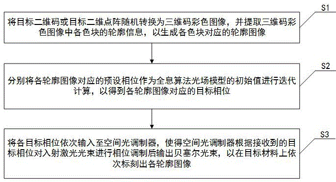
为实现上述目的,按照本发明的一个方面,提供了一种基于空间光调制器的三维码激光标刻方法,所述空间光调制器中叠加有相移菲涅尔透镜、空间光栅和贝塞尔整形透镜,方法包括:S1,将目标二维码或目标二维点阵随机转换为三维码彩色图像,并提取所述三维码彩色图像中各色块的轮廓信息,以生成所述各色块对应的轮廓图像;S2,分别将各所述轮廓图像对应的预设相位作为全息算法光场模型的初始值进行迭代计算,以得到各所述轮廓图像对应的目标相位;S3,将各所述目标相位依次输入至所述空间光调制器,使得所述空间光调制器根据接收到的目标相位对入射激光光束进行相位调制后输出贝塞尔光束,以在目标材料上依次标刻出各所述轮廓图像。In order to achieve the above object, according to one aspect of the present invention, a three-dimensional code laser marking method based on a spatial light modulator is provided, wherein the spatial light modulator is superimposed with a phase shift Fresnel lens, a spatial grating and a Bessel. and the method includes: S1, randomly converting a target two-dimensional code or a target two-dimensional dot matrix into a color image of a three-dimensional code, and extracting the contour information of each color block in the color image of the three-dimensional code, so as to generate a corresponding color block for each color block. S2, use the preset phase corresponding to each described outline image as the initial value of the holographic algorithm light field model to perform iterative calculation to obtain the target phase corresponding to each described outline image; S3, use each described target phase The phases are sequentially input to the spatial light modulator, so that the spatial light modulator performs phase modulation on the incident laser beam according to the received target phase and then outputs a Bessel beam, so as to mark the target material in turn. Outline image.
更进一步地,所述S1包括:根据初始信息生成所述目标二维码或目标二维点阵;将所述目标二维码或目标二维点阵分割为多个最小标刻单元,并添加随机色块以生成所述三维码彩色图像;利用腐蚀算法对所述三维码彩色图像进行扩散以提取所述各色块的轮廓信息。Further, the S1 includes: generating the target two-dimensional code or the target two-dimensional lattice according to the initial information; dividing the target two-dimensional code or the target two-dimensional lattice into a plurality of minimum marking units, and adding random color blocks to generate the color image of the three-dimensional code; using an erosion algorithm to diffuse the color image of the three-dimensional code to extract the contour information of the color blocks.
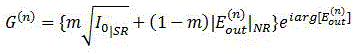
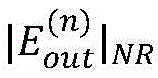
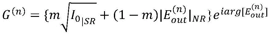
更进一步地,所述全息算法光场模型基于模拟退火算法和强度传输方程生成,生成的全息算法光场模型为:Further, the holographic algorithm light field model is generated based on the simulated annealing algorithm and the intensity transfer equation, and the generated holographic algorithm light field model is:
其中,


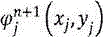
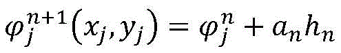
更进一步地,所述全息算法光场模型中相位的迭代方程为:Further, the iterative equation of the phase in the light field model of the holographic algorithm is:

其中,


更进一步地,所述S2中分别将各所述轮廓图像对应的预设相位作为全息算法光场模型的初始值进行迭代计算包括:将各所述轮廓图像的幅值设置为目标幅值,并根据各所述目标幅值在预置配置文件中读取相应的预设相位;分别将各所述轮廓图像对应的预设相位作为所述全息算法光场模型的初始值,并以各所述轮廓图像对应的目标幅值作为所述全息算法光场模型的目标值进行迭代计算,以得到各所述目标相位。Further, in the step S2, using the preset phase corresponding to each contour image as the initial value of the holographic algorithm light field model to perform iterative calculation includes: setting the amplitude value of each contour image as the target amplitude value, and Read the corresponding preset phase in the preset configuration file according to each of the target amplitudes; take the preset phase corresponding to each of the contour images as the initial value of the light field model of the holographic algorithm, and use the The target amplitude corresponding to the contour image is used as the target value of the light field model of the holographic algorithm to perform iterative calculation to obtain each target phase.
更进一步地,所述S3中输出所述贝塞尔光束之前还包括:屏蔽所述贝塞尔光束中的零极光后输出所述贝塞尔光束。Further, before outputting the Bessel beam in S3, the method further includes: outputting the Bessel beam after shielding the zero aurora in the Bessel beam.
更进一步地,所述S3中输出所述贝塞尔光束之前还包括:保留所述贝塞尔光束中的零极光并输出所述贝塞尔光束,以在目标材料上依次标刻出各所述轮廓图像。Further, before outputting the Bessel beam in S3, the method further includes: retaining the zero aurora in the Bessel beam and outputting the Bessel beam, so as to mark each beam on the target material in turn. the outline image.
更进一步地,所述S3中通过调节所述相移菲涅尔透镜和/或空间光栅,来调节所述贝塞尔光束的水平位置和轴向焦点。Further, in S3, the horizontal position and the axial focus of the Bessel beam are adjusted by adjusting the phase-shifting Fresnel lens and/or the space grating.
更进一步地,在所述S1之前,所述方法还包括:通过物理冷却方式将所述空间光调制器的光损伤阈值增加至40W/cm2-150W/cm2。Further, before the S1, the method further includes: increasing the light damage threshold of the spatial light modulator to 40W/cm 2 -150W/cm 2 by means of physical cooling.
按照本发明的另一个方面,提供了一种基于空间光调制器的三维码激光标刻系统,所述空间光调制器中叠加有相移菲涅尔透镜、空间光栅和贝塞尔整形透镜,系统包括:转换及提取模块,用于将目标二维码或目标二维点阵随机转换为三维码彩色图像,并提取所述三维码彩色图像中各色块的轮廓信息,以生成所述各色块对应的轮廓图像;计算模块,用于分别将各所述轮廓图像对应的预设相位作为全息算法光场模型的初始值进行迭代计算,以得到各所述轮廓图像对应的目标相位;叠加模块,用于在所述空间光调制器中叠加相移菲涅尔透镜、空间光栅和贝塞尔整形透镜;调制及标刻模块,用于将各所述目标相位依次输入至所述空间光调制器,使得所述空间光调制器根据接收到的目标相位对入射激光光束进行相位调制后输出贝塞尔光束,以在目标材料上依次标刻出各所述轮廓图像。According to another aspect of the present invention, a three-dimensional code laser marking system based on a spatial light modulator is provided, wherein the spatial light modulator is superimposed with a phase-shifting Fresnel lens, a spatial grating and a Bessel shaping lens, The system includes: a conversion and extraction module for randomly converting a target two-dimensional code or a target two-dimensional dot matrix into a color image of a three-dimensional code, and extracting the outline information of each color block in the color image of the three-dimensional code to generate the color block a corresponding contour image; a calculation module for performing iterative calculation with the preset phase corresponding to each of the contour images as the initial value of the light field model of the holographic algorithm, so as to obtain the target phase corresponding to each of the contour images; a superposition module, for stacking phase-shifted Fresnel lenses, spatial gratings and Bessel shaping lenses in the spatial light modulator; a modulation and marking module for sequentially inputting each of the target phases to the spatial light modulator , so that the spatial light modulator phase-modulates the incident laser beam according to the received target phase and then outputs a Bessel beam, so as to mark the contour images on the target material in sequence.
总体而言,通过本发明所构思的以上技术方案,能够取得以下有益效果:In general, through the above technical solutions conceived by the present invention, the following beneficial effects can be achieved:
(1)在黑白二维码和点阵的基础上添加三维码信息,提高了二维码的防伪性、随机性和存储能力;获取相应的三维轮廓信息,将三维轮廓信息对应的三张全息相位图依次加载到空间光调制器进行三维码激光标刻,在光路不变的情况下实现多焦点标刻,提高标刻速率;(1) Add 3D code information on the basis of black and white QR code and dot matrix, which improves the anti-counterfeiting, randomness and storage capacity of QR code; obtains the corresponding 3D contour information, and converts the three holograms corresponding to the 3D contour information. The phase map is sequentially loaded into the spatial light modulator for 3D code laser marking, and multi-focus marking is realized under the condition of the same optical path, which improves the marking rate;
(2)在空间光调制器中叠加相移菲涅尔透镜、空间光栅和贝塞尔整形透镜,以将入射激光光束整形为贝塞尔光束,同等激光功率下提高了标刻均匀性和分辨率,并且可以在不改变激光光束的情况下实现不同位置和焦点处的标刻;(2) A phase-shifting Fresnel lens, a spatial grating and a Bessel shaping lens are superimposed in the spatial light modulator to shape the incident laser beam into a Bessel beam, which improves marking uniformity and resolution under the same laser power. rate, and marking at different positions and focal points can be achieved without changing the laser beam;
(3)迭代计算调制相位时增大迭代步长,并设计三维码光场能量均匀度作为迭代条件,对标刻分辨率和标刻速度同时进行优化;(3) Increase the iterative step size when iteratively calculate the modulation phase, and design the energy uniformity of the 3D code optical field as an iterative condition to optimize the marking resolution and marking speed at the same time;
(4)通过分离屏蔽贝塞尔光束中的零极光,进一步提高了标刻分辨率。(4) The marking resolution is further improved by separating and shielding the zero aurora in the Bessel beam.
附图说明Description of drawings
图1为本发明实施例提出的基于空间光调制器的三维码激光标刻方法的流程图;1 is a flowchart of a method for laser marking of three-dimensional codes based on a spatial light modulator proposed by an embodiment of the present invention;
图2为基于空间光调制器形成的三维码标刻装置的结构示意图;2 is a schematic structural diagram of a three-dimensional code marking device formed based on a spatial light modulator;
图3为本发明实施例提出的基于空间光调制器的三维码激光标刻方法的标刻流程示意图;3 is a schematic diagram of a marking process of a three-dimensional code laser marking method based on a spatial light modulator proposed by an embodiment of the present invention;
图4为本发明实施例提出的基于空间光调制器的三维码激光标刻系统的框图。FIG. 4 is a block diagram of a three-dimensional code laser marking system based on a spatial light modulator according to an embodiment of the present invention.
在所有附图中,相同的附图标记用来表示相同的元件或者结构,其中:Throughout the drawings, the same reference numbers are used to refer to the same elements or structures, wherein:
1为激光器,2为半波片分束器组合,3为反射镜,4为扩束镜,5为空间光调制器,6为上位机,7为光阑,8为聚焦系统,9为聚焦面。1 is the laser, 2 is the half-wave plate beam splitter combination, 3 is the mirror, 4 is the beam expander, 5 is the spatial light modulator, 6 is the upper computer, 7 is the diaphragm, 8 is the focusing system, and 9 is the focusing noodle.
具体实施方式Detailed ways
为了使本发明的目的、技术方案及优点更加清楚明白,以下结合附图及实施例,对本发明进行进一步详细说明。应当理解,此处所描述的具体实施例仅仅用以解释本发明,并不用于限定本发明。此外,下面所描述的本发明各个实施方式中所涉及到的技术特征只要彼此之间未构成冲突就可以相互组合。In order to make the objectives, technical solutions and advantages of the present invention clearer, the present invention will be further described in detail below with reference to the accompanying drawings and embodiments. It should be understood that the specific embodiments described herein are only used to explain the present invention, but not to limit the present invention. In addition, the technical features involved in the various embodiments of the present invention described below can be combined with each other as long as there is no conflict with each other.
在本发明中,本发明及附图中的术语“第一”、“第二”等(如果存在)是用于区别类似的对象,而不必用于描述特定的顺序或先后次序。In the present invention, the terms "first", "second" and the like (if any) in the present invention and the accompanying drawings are used to distinguish similar objects, and are not necessarily used to describe a specific order or sequence.
图1为本发明实施例提出的基于空间光调制器的三维码激光标刻方法的流程图。参阅图1,结合图2-图3,对本实施例中基于空间光调制器的三维码激光标刻方法进行详细说明,方法包括操作S1-操作S3。FIG. 1 is a flowchart of a three-dimensional code laser marking method based on a spatial light modulator according to an embodiment of the present invention. Referring to FIG. 1 , in conjunction with FIGS. 2 to 3 , the method for marking a three-dimensional code laser based on a spatial light modulator in this embodiment will be described in detail. The method includes operations S1 to S3 .
操作S1,将目标二维码或目标二维点阵随机转换为三维码彩色图像,并提取三维码彩色图像中各色块的轮廓信息,以生成各色块对应的轮廓图像。In operation S1, the target two-dimensional code or the target two-dimensional dot matrix is randomly converted into a color image of the three-dimensional code, and the contour information of each color block in the color image of the three-dimensional code is extracted to generate a contour image corresponding to each color block.
根据本发明实施例,操作S1包括子操作S11-子操作S13。According to the embodiment of the present invention, operation S1 includes sub-operation S11-sub-operation S13.
在子操作S11中,根据初始信息生成所述目标二维码或目标二维点阵。初始信息是指待编码的数据信息。In sub-operation S11, the target two-dimensional code or the target two-dimensional lattice is generated according to the initial information. The initial information refers to the data information to be encoded.
在子操作S12中,将目标二维码或目标二维点阵分割为多个最小标刻单元,并添加随机色块以生成三维码彩色图像。最小标刻单元是指组成二维码或二维点阵的最小黑白方格。本实施例中,以最小图形单元为单位随机生成颜色信息,并保证颜色复杂度适中,直接使用颜色种子生长得到随机性更高的三维码,得到的三维码彩色图像由三种不同颜色的色块组成。由于添加色块的随机性,保证了三维码彩色图像的随机性,使得三维码难以复制,提高了防伪的能力。操作S12中生成的三维码彩色图像如图3中最左侧图所示。In sub-operation S12, the target two-dimensional code or the target two-dimensional dot matrix is divided into a plurality of minimum marking units, and random color blocks are added to generate a color image of the three-dimensional code. The smallest marking unit refers to the smallest black and white squares that form a two-dimensional code or two-dimensional lattice. In this embodiment, color information is randomly generated with the smallest graphic unit as the unit, and the color complexity is ensured, and a 3D code with higher randomness is obtained directly by using color seeds to grow, and the obtained 3D code color image is composed of three different colors. block composition. Due to the randomness of the added color blocks, the randomness of the color image of the three-dimensional code is guaranteed, which makes it difficult to copy the three-dimensional code and improves the anti-counterfeiting ability. The color image of the three-dimensional code generated in operation S12 is shown in the leftmost figure in FIG. 3 .
在子操作S13中,利用腐蚀算法对三维码彩色图像进行扩散以提取各色块的轮廓信息。进一步地,将同一颜色色块提取出来形成该色块对应的轮廓图像,由此,可以生成三张轮廓图像,分别对应三种不同颜色的色块。生成的轮廓图像如图3左侧第二栏图所示。In sub-operation S13, the 3D code color image is diffused using an erosion algorithm to extract contour information of each color block. Further, a color block of the same color is extracted to form a contour image corresponding to the color block, thereby three contour images can be generated, corresponding to three color blocks of different colors respectively. The resulting contour image is shown in the second column from the left of Figure 3.
操作S2,分别将各轮廓图像对应的预设相位作为全息算法光场模型的初始值进行迭代计算,以得到各轮廓图像对应的目标相位。In operation S2, the preset phase corresponding to each contour image is used as the initial value of the light field model of the holographic algorithm to perform iterative calculation, so as to obtain the target phase corresponding to each contour image.
根据本发明实施例,全息算法光场模型基于模拟退火算法和强度传输方程(Transport of Intensity Equation,TIE)生成,生成的全息算法光场模型为:According to the embodiment of the present invention, the light field model of the holographic algorithm is generated based on the simulated annealing algorithm and the Transport of Intensity Equation (TIE), and the generated light field model of the holographic algorithm is:

其中,


其中,


根据本发明实施例,操作S2包括子操作S21和子操作S22。According to the embodiment of the present invention, operation S2 includes sub-operation S21 and sub-operation S22.
在子操作S21中,将各轮廓图像的幅值设置为目标幅值,并根据各目标幅值在预置配置文件中读取相应的预设相位。In sub-operation S21, the amplitude of each contour image is set as the target amplitude, and the corresponding preset phase is read in the preset configuration file according to each target amplitude.
对于操作S1中生成三张轮廓图像,分别计算这三张轮廓图像的幅值,该幅值即为激光标刻的目标幅值。预置配置文件中存储有常规三维码标刻调制相关信息,例如包括预设相位,将该预设相位作为计算全息的初始相位。For the three contour images generated in operation S1, the amplitudes of the three contour images are calculated respectively, and the amplitudes are the target amplitudes for laser marking. The preset configuration file stores information related to conventional three-dimensional code marking modulation, for example, includes a preset phase, and the preset phase is used as the initial phase for calculating the hologram.
在子操作S22中,分别将各轮廓图像对应的预设相位作为所述光场模型的初始值,并以各轮廓图像对应的目标幅值作为光场模型的目标值进行迭代计算,以得到各目标相位。In sub-operation S22, the preset phase corresponding to each contour image is used as the initial value of the light field model, and the target amplitude corresponding to each contour image is used as the target value of the light field model to perform iterative calculation, so as to obtain each target phase.
对于任一轮廓图像而言,将该轮廓图像对应的初始相位代入全息算法光场模型中进行迭代计算,得到相应的迭代相位以及与该迭代相位对应的光场幅值,直至某次迭代得到的光场幅值等于该轮廓图像对应的目标幅值,则停止迭代计算,并将此次迭代计算得到的迭代相位设置为目标相位,从而得到各轮廓图像对应的全息相位图,如图3左侧第三栏图所示。For any contour image, the initial phase corresponding to the contour image is substituted into the light field model of the holographic algorithm for iterative calculation, and the corresponding iterative phase and the light field amplitude corresponding to the iterative phase are obtained. If the amplitude of the light field is equal to the target amplitude corresponding to the contour image, the iterative calculation is stopped, and the iterative phase obtained by this iterative calculation is set as the target phase, so as to obtain the holographic phase map corresponding to each contour image, as shown on the left side of Figure 3 shown in the third column.
本发明实施例中,空间光调制器中叠加有相移菲涅尔透镜、空间光栅和贝塞尔整形透镜。In the embodiment of the present invention, a phase shift Fresnel lens, a spatial grating and a Bessel shaping lens are superimposed in the spatial light modulator.
空间光调制器是指在主动控制下,可以通过液晶分子调制光场的某个参量,从而将一定的信息写入光波中,达到光波调制目的的器件,例如调制光波的振幅、相位、偏振态等。空间光调制器的调制效果是可以自定义的。本实施例中,对空间光调制器进行控制以实现相移菲涅尔透镜、空间光栅和贝塞尔整形透镜的相位调制效果。Spatial light modulator refers to a device that can modulate a certain parameter of the light field through liquid crystal molecules under active control, thereby writing certain information into the light wave to achieve the purpose of light wave modulation, such as modulating the amplitude, phase, and polarization state of the light wave. Wait. The modulation effect of the spatial light modulator can be customized. In this embodiment, the spatial light modulator is controlled to realize the phase modulation effect of the phase-shifted Fresnel lens, the spatial grating and the Bessel shaping lens.
通过加载贝塞尔整形透镜的相位,可以将入射激光光束由高斯光束调制整形为贝塞尔光束,相比普通高斯光束,在进行点阵的印章式标刻时,边缘光强分布更均匀。通过加载空间光栅和相移菲涅尔透镜,可以调节三维码标刻的水平位置和轴向焦点位置而不需要移动平台。By loading the phase of the Bessel shaping lens, the incident laser beam can be modulated and shaped into a Bessel beam from a Gaussian beam. Compared with an ordinary Gaussian beam, the edge light intensity distribution is more uniform when stamping a dot matrix. By loading a space grating and a phase-shifting Fresnel lens, the horizontal position and axial focus position of the 3D code marking can be adjusted without moving the stage.
操作S3,将各目标相位依次输入至空间光调制器,使得空间光调制器根据接收到的目标相位对入射激光光束进行相位调制后输出贝塞尔光束,以在目标材料上依次标刻出各轮廓图像。In operation S3, each target phase is sequentially input to the spatial light modulator, so that the spatial light modulator performs phase modulation on the incident laser beam according to the received target phase, and then outputs a Bessel beam, so as to sequentially mark each target material on the target material. Outline image.
本发明实施例中,三维码标刻所用到的标刻装置如图2所示。参阅图2,该标刻装置包括激光器1、半波片分束器组合2、反射镜3、扩束镜4、空间光调制器5、上位机6、光阑7、聚焦系统8和聚焦面9。该基于空间光调制器的三维码激光标刻方法例如在上位机6中执行,上位机6例如为计算机。In the embodiment of the present invention, the marking device used for marking the three-dimensional code is shown in FIG. 2 . Referring to Figure 2, the marking device includes a
激光器1例如为光纤激光器,功率范围为10W-20W,波长例如为1064nm,脉冲宽度例如为20ns,可根据空间光调制器5的损伤阈值和工作波长对应更换激光器1。半波片分束器组合2用于控制激光器1输出的激光光束的能量,防止激光光束输出功率超过空间光调制器5的损伤阈值。扩束镜4用于保证激光光束直径略大于空间光调制器5的液晶面,使得空间光调制器5的有限像素得到充分利用以及提高整个调制面光强的均匀性。扩束镜4处激光光束的偏振方向应当和液晶面的液晶分子取向保持一致,以保证调制过程是纯相位调制。空间光调制器5连接上位机6,通过加载上位机6中输出的复合相位图来对激光光束进行相位调制并输出贝塞尔光束。当空间光调制器5输出的光束有多个衍射级次时,在进行高精度标刻时,将+1级的调制光通过光阑7,其他光被阻拦在光阑7之外。聚焦系统8用于将调制得到的贝塞尔光束聚焦到标刻平面上,标刻平面位于聚焦面9处。目标材料位于聚焦面9。The
激光器1产生的激光光束依次经过半波片分束器组合2、反射镜3、扩束镜4后到达空间光调制器5,空间光调制器5在上位机6的控制下对激光光束进行相位调制以输出贝塞尔光束,贝塞尔光束依次经过光阑7和聚焦系统8后到达聚焦面9,对聚焦面9处的目标材料进行标刻。The laser beam generated by the
进一步地,为了提高标刻精度和标刻图案均匀度,空间光调制器5在对激光光束进行相位调制之前,先加载贝塞尔整形透镜将激光光束调制为贝塞尔光束;然后加载任一轮廓图像对应的目标相位,并添加相移菲涅尔透镜和空间光栅,通过调节相移菲涅尔透镜和/或空间光栅来调节贝塞尔光束的水平位置和轴向焦点,达到对不同颜色区域不同焦距标刻的目的。激光光束经过空间光调制器5后,不同颜色信息对应的三维码部分在标刻面附近的不同焦距处标刻,最终形成表面凹凸有致的防伪三维码图样,如图3最右侧图所示。Further, in order to improve marking accuracy and marking pattern uniformity, the spatial
本发明一实施例中,操作S3中控制空间光调制器5屏蔽贝塞尔光束中的零极光并输出贝塞尔光束,以在目标材料上依次标刻出各轮廓图像。从而有效提高标刻分辨率。In an embodiment of the present invention, in operation S3, the spatial
本发明另一实施例中,操作S3中控制空间光调制器5保留贝塞尔光束中的零极光并输出贝塞尔光束,以在目标材料上依次标刻出各轮廓图像。从而在保证标刻分辨率的情况下加强光利用率。In another embodiment of the present invention, in operation S3, the spatial
根据本发明实施例,在执行操作S1之前,需要通过物理冷却方式将空间光调制器的光损伤阈值增加至40W/cm2-150W/cm2,以符合标刻需求。物理冷却方式例如为水冷、风冷等。According to the embodiment of the present invention, before the operation S1 is performed, the light damage threshold of the spatial light modulator needs to be increased to 40W/cm 2 -150W/cm 2 by means of physical cooling to meet the marking requirements. Physical cooling methods are, for example, water cooling, air cooling, and the like.
图4为本发明实施例提出的基于空间光调制器的三维码激光标刻系统的结构框图。参阅图4,该基于空间光调制器的三维码激光标刻系统400包括转换及提取模块410、计算模块420以及调制及标刻模块430。空间光调制器中叠加有相移菲涅尔透镜、空间光栅和贝塞尔整形透镜。FIG. 4 is a structural block diagram of a three-dimensional code laser marking system based on a spatial light modulator according to an embodiment of the present invention. Referring to FIG. 4 , the three-dimensional code
提取模块410例如执行操作S1,用于将目标二维码或目标二维点阵随机转换为三维码彩色图像,并提取三维码彩色图像中各色块的轮廓信息,以生成各色块对应的轮廓图像。The
计算模块420例如执行操作S2,用于分别将各轮廓图像对应的预设相位作为全息算法光场模型的初始值进行迭代计算,以得到各轮廓图像对应的目标相位。The
调制及标刻模块430例如执行操作S3,用于将各目标相位依次输入至空间光调制器,使得空间光调制器根据接收到的目标相位对入射激光光束进行相位调制后输出贝塞尔光束,以在目标材料上依次标刻出各轮廓图像。The modulation and marking
基于空间光调制器的三维码激光标刻系统400用于执行上述图1-图3所示实施例中的基于空间光调制器的三维码激光标刻方法。本实施例未尽之细节,请参阅前述图1-图3所示实施例中的基于空间光调制器的三维码激光标刻方法,此处不再赘述。The three-dimensional code
本领域的技术人员容易理解,以上所述仅为本发明的较佳实施例而已,并不用以限制本发明,凡在本发明的精神和原则之内所作的任何修改、等同替换和改进等,均应包含在本发明的保护范围之内。Those skilled in the art can easily understand that the above are only preferred embodiments of the present invention, and are not intended to limit the present invention. Any modifications, equivalent replacements and improvements made within the spirit and principles of the present invention, etc., All should be included within the protection scope of the present invention.
Claims (8)


Priority Applications (1)
| Application Number | Priority Date | Filing Date | Title |
|---|---|---|---|
| CN202011351817.5A CN112276370B (en) | 2020-11-27 | 2020-11-27 | A three-dimensional code laser marking method and system based on spatial light modulator |
Applications Claiming Priority (1)
| Application Number | Priority Date | Filing Date | Title |
|---|---|---|---|
| CN202011351817.5A CN112276370B (en) | 2020-11-27 | 2020-11-27 | A three-dimensional code laser marking method and system based on spatial light modulator |
Publications (2)
| Publication Number | Publication Date |
|---|---|
| CN112276370A CN112276370A (en) | 2021-01-29 |
| CN112276370B true CN112276370B (en) | 2021-10-08 |
Family
ID=74425492
Family Applications (1)
| Application Number | Title | Priority Date | Filing Date |
|---|---|---|---|
| CN202011351817.5A Active CN112276370B (en) | 2020-11-27 | 2020-11-27 | A three-dimensional code laser marking method and system based on spatial light modulator |
Country Status (1)
| Country | Link |
|---|---|
| CN (1) | CN112276370B (en) |
Families Citing this family (1)
| Publication number | Priority date | Publication date | Assignee | Title |
|---|---|---|---|---|
| CN117454657B (en) * | 2023-11-15 | 2024-07-19 | 武汉华日精密激光股份有限公司 | Laser modulation output method and system based on path planning |
Citations (1)
| Publication number | Priority date | Publication date | Assignee | Title |
|---|---|---|---|---|
| CN102981277A (en) * | 2012-12-12 | 2013-03-20 | 苏州大学 | System and method for generating radial Bessel-Gaussian beam |
Family Cites Families (7)
| Publication number | Priority date | Publication date | Assignee | Title |
|---|---|---|---|---|
| US6356649B2 (en) * | 1997-04-11 | 2002-03-12 | Arete Associate, Inc. | “Systems and methods with identity verification by streamlined comparison and interpretation of fingerprints and the like” |
| US7873476B2 (en) * | 2008-07-02 | 2011-01-18 | Chevron U.S.A. Inc. | Well log correlation |
| US9032276B2 (en) * | 2012-09-25 | 2015-05-12 | Avago Technologies General Ip (Singapore) Pte. Ltd. | Method and system for generation of a tie-breaking metric in a low-density parity check data encoding system |
| CN104118220A (en) * | 2014-03-28 | 2014-10-29 | 上海飞涅尔激光科技有限公司 | Two-dimensional code laser marking method and device based on liquid crystal spatial light modulator |
| CA3053009A1 (en) * | 2017-02-08 | 2018-08-16 | Essenlix Corporation | Optics, device, and system for assaying |
| CN110348553B (en) * | 2019-06-30 | 2021-01-26 | 东莞市恒德光电设备制造有限公司 | Laser marking method for random three-dimensional code |
| CN111884019B (en) * | 2020-08-17 | 2021-03-30 | 武汉金顿激光科技有限公司 | Three-dimensional multi-beam laser parameter regulation and control method and system |
-
2020
- 2020-11-27 CN CN202011351817.5A patent/CN112276370B/en active Active
Patent Citations (1)
| Publication number | Priority date | Publication date | Assignee | Title |
|---|---|---|---|---|
| CN102981277A (en) * | 2012-12-12 | 2013-03-20 | 苏州大学 | System and method for generating radial Bessel-Gaussian beam |
Also Published As
| Publication number | Publication date |
|---|---|
| CN112276370A (en) | 2021-01-29 |
Similar Documents
| Publication | Publication Date | Title |
|---|---|---|
| JP6858717B2 (en) | Dynamic holography Depth of focus printing device | |
| CN106199800B (en) | A kind of integrated approach of the three-dimensional vortex array of spatial distribution | |
| Liu et al. | High-speed full analytical holographic computations for true-life scenes | |
| US10802440B2 (en) | Dynamic holography non-scanning printing device | |
| Bañas et al. | GPC light shaper for speckle-free one-and two-photon contiguous pattern excitation | |
| US20190004476A1 (en) | Dynamic Holography Printing Device | |
| Ogura et al. | Design and demonstration of fan-out elements generating an array of subdiffraction spots | |
| Khuderchuluun et al. | Simplified digital content generation based on an inverse-directed propagation algorithm for holographic stereogram printing | |
| CN112276370B (en) | A three-dimensional code laser marking method and system based on spatial light modulator | |
| CN117687129B (en) | A light-addressable pixelated spatial light modulator and a spatial light field modulation method | |
| Huang et al. | Multi-value phase grating fabrication using direct laser writing for generating a two-dimensional focal spot array | |
| CN108919499B (en) | Method for generating multiple focusing light spots with independently controllable positions and intensities | |
| RU2396584C1 (en) | Method of creating holographic images of drawing | |
| CN111949067A (en) | Daman Convolutional Optical Computer | |
| Tsang et al. | Enhancing the pictorial content of digital holograms at 100 frames per second | |
| Vaziri et al. | A simple method to prepare and characterize optical fork-shaped diffraction gratings for generation of orbital angular momentum beams | |
| RU2498380C2 (en) | Device for recording microholograms | |
| CN118409437A (en) | System and method for generating and detecting central rotationally symmetric array structure light field | |
| Zheng | Hexagonal diffractive optical elements and phase retrieval algorithms | |
| He et al. | High‐Speed Design of Multiplexed Meta‐Optics Enabled by Physics‐Driven Self‐Supervised Network | |
| JP6143052B2 (en) | Random phase mask for Fourier transform hologram | |
| Zhang et al. | Defective states of Hermite-Gaussian modes for long-distance image transmission and high-capacity encoding | |
| Choi et al. | Neural 360$^\circ $ Structured Light with Learned Metasurfaces | |
| JP2019133002A (en) | Diffraction element | |
| Zhang et al. | Defective States of Structured Light for High-Capacity Information Transmission |
Legal Events
| Date | Code | Title | Description |
|---|---|---|---|
| PB01 | Publication | ||
| PB01 | Publication | ||
| SE01 | Entry into force of request for substantive examination | ||
| SE01 | Entry into force of request for substantive examination | ||
| GR01 | Patent grant | ||
| GR01 | Patent grant |