CN112272763B - Abnormality detection device, abnormality detection method, and computer-readable storage medium - Google Patents
Abnormality detection device, abnormality detection method, and computer-readable storage medium Download PDFInfo
- Publication number
- CN112272763B CN112272763B CN201880094472.4A CN201880094472A CN112272763B CN 112272763 B CN112272763 B CN 112272763B CN 201880094472 A CN201880094472 A CN 201880094472A CN 112272763 B CN112272763 B CN 112272763B
- Authority
- CN
- China
- Prior art keywords
- offset
- abnormality
- data
- similarity
- abnormality detection
- Prior art date
- Legal status (The legal status is an assumption and is not a legal conclusion. Google has not performed a legal analysis and makes no representation as to the accuracy of the status listed.)
- Active
Links
Images


Classifications
-
- G—PHYSICS
- G06—COMPUTING OR CALCULATING; COUNTING
- G06F—ELECTRIC DIGITAL DATA PROCESSING
- G06F17/00—Digital computing or data processing equipment or methods, specially adapted for specific functions
- G06F17/10—Complex mathematical operations
- G06F17/18—Complex mathematical operations for evaluating statistical data, e.g. average values, frequency distributions, probability functions, regression analysis
-
- G—PHYSICS
- G01—MEASURING; TESTING
- G01M—TESTING STATIC OR DYNAMIC BALANCE OF MACHINES OR STRUCTURES; TESTING OF STRUCTURES OR APPARATUS, NOT OTHERWISE PROVIDED FOR
- G01M99/00—Subject matter not provided for in other groups of this subclass
- G01M99/008—Subject matter not provided for in other groups of this subclass by doing functionality tests
-
- G—PHYSICS
- G05—CONTROLLING; REGULATING
- G05B—CONTROL OR REGULATING SYSTEMS IN GENERAL; FUNCTIONAL ELEMENTS OF SUCH SYSTEMS; MONITORING OR TESTING ARRANGEMENTS FOR SUCH SYSTEMS OR ELEMENTS
- G05B23/00—Testing or monitoring of control systems or parts thereof
- G05B23/02—Electric testing or monitoring
- G05B23/0205—Electric testing or monitoring by means of a monitoring system capable of detecting and responding to faults
- G05B23/0218—Electric testing or monitoring by means of a monitoring system capable of detecting and responding to faults characterised by the fault detection method dealing with either existing or incipient faults
- G05B23/0224—Process history based detection method, e.g. whereby history implies the availability of large amounts of data
- G05B23/0227—Qualitative history assessment, whereby the type of data acted upon, e.g. waveforms, images or patterns, is not relevant, e.g. rule based assessment; if-then decisions
- G05B23/0237—Qualitative history assessment, whereby the type of data acted upon, e.g. waveforms, images or patterns, is not relevant, e.g. rule based assessment; if-then decisions based on parallel systems, e.g. comparing signals produced at the same time by same type systems and detect faulty ones by noticing differences among their responses
-
- G—PHYSICS
- G05—CONTROLLING; REGULATING
- G05B—CONTROL OR REGULATING SYSTEMS IN GENERAL; FUNCTIONAL ELEMENTS OF SUCH SYSTEMS; MONITORING OR TESTING ARRANGEMENTS FOR SUCH SYSTEMS OR ELEMENTS
- G05B23/00—Testing or monitoring of control systems or parts thereof
- G05B23/02—Electric testing or monitoring
- G05B23/0205—Electric testing or monitoring by means of a monitoring system capable of detecting and responding to faults
- G05B23/0259—Electric testing or monitoring by means of a monitoring system capable of detecting and responding to faults characterized by the response to fault detection
- G05B23/0275—Fault isolation and identification, e.g. classify fault; estimate cause or root of failure
- G05B23/0281—Quantitative, e.g. mathematical distance; Clustering; Neural networks; Statistical analysis
-
- G—PHYSICS
- G05—CONTROLLING; REGULATING
- G05B—CONTROL OR REGULATING SYSTEMS IN GENERAL; FUNCTIONAL ELEMENTS OF SUCH SYSTEMS; MONITORING OR TESTING ARRANGEMENTS FOR SUCH SYSTEMS OR ELEMENTS
- G05B23/00—Testing or monitoring of control systems or parts thereof
- G05B23/02—Electric testing or monitoring
- G05B23/0205—Electric testing or monitoring by means of a monitoring system capable of detecting and responding to faults
- G05B23/0259—Electric testing or monitoring by means of a monitoring system capable of detecting and responding to faults characterized by the response to fault detection
- G05B23/0283—Predictive maintenance, e.g. involving the monitoring of a system and, based on the monitoring results, taking decisions on the maintenance schedule of the monitored system; Estimating remaining useful life [RUL]
-
- G—PHYSICS
- G06—COMPUTING OR CALCULATING; COUNTING
- G06F—ELECTRIC DIGITAL DATA PROCESSING
- G06F18/00—Pattern recognition
- G06F18/10—Pre-processing; Data cleansing
- G06F18/15—Statistical pre-processing, e.g. techniques for normalisation or restoring missing data
-
- G—PHYSICS
- G06—COMPUTING OR CALCULATING; COUNTING
- G06F—ELECTRIC DIGITAL DATA PROCESSING
- G06F18/00—Pattern recognition
- G06F18/20—Analysing
- G06F18/21—Design or setup of recognition systems or techniques; Extraction of features in feature space; Blind source separation
- G06F18/217—Validation; Performance evaluation; Active pattern learning techniques
- G06F18/2193—Validation; Performance evaluation; Active pattern learning techniques based on specific statistical tests
-
- G—PHYSICS
- G06—COMPUTING OR CALCULATING; COUNTING
- G06F—ELECTRIC DIGITAL DATA PROCESSING
- G06F18/00—Pattern recognition
- G06F18/20—Analysing
- G06F18/22—Matching criteria, e.g. proximity measures
-
- G—PHYSICS
- G06—COMPUTING OR CALCULATING; COUNTING
- G06F—ELECTRIC DIGITAL DATA PROCESSING
- G06F18/00—Pattern recognition
- G06F18/20—Analysing
- G06F18/24—Classification techniques
- G06F18/243—Classification techniques relating to the number of classes
- G06F18/2433—Single-class perspective, e.g. one-against-all classification; Novelty detection; Outlier detection
-
- G—PHYSICS
- G06—COMPUTING OR CALCULATING; COUNTING
- G06F—ELECTRIC DIGITAL DATA PROCESSING
- G06F18/00—Pattern recognition
- G06F18/20—Analysing
- G06F18/28—Determining representative reference patterns, e.g. by averaging or distorting; Generating dictionaries
-
- G—PHYSICS
- G01—MEASURING; TESTING
- G01R—MEASURING ELECTRIC VARIABLES; MEASURING MAGNETIC VARIABLES
- G01R31/00—Arrangements for testing electric properties; Arrangements for locating electric faults; Arrangements for electrical testing characterised by what is being tested not provided for elsewhere
-
- G—PHYSICS
- G05—CONTROLLING; REGULATING
- G05B—CONTROL OR REGULATING SYSTEMS IN GENERAL; FUNCTIONAL ELEMENTS OF SUCH SYSTEMS; MONITORING OR TESTING ARRANGEMENTS FOR SUCH SYSTEMS OR ELEMENTS
- G05B23/00—Testing or monitoring of control systems or parts thereof
- G05B23/02—Electric testing or monitoring
- G05B23/0205—Electric testing or monitoring by means of a monitoring system capable of detecting and responding to faults
- G05B23/0218—Electric testing or monitoring by means of a monitoring system capable of detecting and responding to faults characterised by the fault detection method dealing with either existing or incipient faults
- G05B23/0224—Process history based detection method, e.g. whereby history implies the availability of large amounts of data
- G05B23/024—Quantitative history assessment, e.g. mathematical relationships between available data; Functions therefor; Principal component analysis [PCA]; Partial least square [PLS]; Statistical classifiers, e.g. Bayesian networks, linear regression or correlation analysis; Neural networks
Landscapes
- Engineering & Computer Science (AREA)
- Physics & Mathematics (AREA)
- General Physics & Mathematics (AREA)
- Data Mining & Analysis (AREA)
- Theoretical Computer Science (AREA)
- Bioinformatics & Cheminformatics (AREA)
- Bioinformatics & Computational Biology (AREA)
- Evolutionary Biology (AREA)
- General Engineering & Computer Science (AREA)
- Life Sciences & Earth Sciences (AREA)
- Artificial Intelligence (AREA)
- Evolutionary Computation (AREA)
- Computer Vision & Pattern Recognition (AREA)
- Probability & Statistics with Applications (AREA)
- Mathematical Optimization (AREA)
- Mathematical Analysis (AREA)
- Pure & Applied Mathematics (AREA)
- Mathematical Physics (AREA)
- Computational Mathematics (AREA)
- Algebra (AREA)
- Automation & Control Theory (AREA)
- Operations Research (AREA)
- Databases & Information Systems (AREA)
- Software Systems (AREA)
- Testing And Monitoring For Control Systems (AREA)
- Testing Of Devices, Machine Parts, Or Other Structures Thereof (AREA)
Abstract
Description
技术领域technical field
本发明涉及根据从对象设备得到的数据探测对象设备的异常的技术。The present invention relates to a technique for detecting an abnormality of a target device based on data obtained from the target device.
背景技术Background technique
在预防性维护以及设备维护的领域中,为了将维护实施以及备件管理不浪费地降至所需最小限而进行探测或者预测设备的劣化以及故障的迹象的技术开发。在关注传感器网络以及大数据解析的过程中,对设备工作状况进行感测,根据物理的解析或者统计预测进行异常探测或者故障预测的技术正被开发。In the field of preventive maintenance and equipment maintenance, technology development for detecting or predicting signs of deterioration and failure of equipment is carried out in order to reduce maintenance implementation and spare parts management to the necessary minimum without waste. In the process of focusing on sensor networks and big data analysis, technologies are being developed to sense the working conditions of equipment and perform abnormal detection or fault prediction based on physical analysis or statistical prediction.
针对设备的异常探测,多数情况采取如下方法:收集设备的工作数据,在掌握正常时以及异常时的数据的特征的基础上,构筑异常探测模型。For the abnormal detection of equipment, the following method is adopted in most cases: collect the working data of the equipment, and build an abnormal detection model on the basis of grasping the characteristics of the normal and abnormal data.
关于专利文献1记载的方法,在工厂的过程监视中,使用多个异常诊断模型来进行异常的探测以及主要原因的提示。在专利文献1中,事先构筑有效利用主成分分析或者离散小波变换的异常诊断模型,将异常诊断模型应用于过程监视中的在线异常探测。Regarding the method described in
在此,为了构筑异常诊断模型,需要解析正常时以及异常时的数据特征,掌握能够推测设备状态的统计特征量。但是,例如发电机以及升降机这样的使用寿命长的设备大部分在故障前被进行维护,所以多数情况下,制造商、维护运营商、以及设备引进者(用户)都不保有故障数据。因此,难以采用事先学习故障时的设备状态以及测量数据的变动来进行异常探测的方式。Here, in order to construct an abnormality diagnosis model, it is necessary to analyze the data characteristics during normal and abnormal conditions, and to grasp the statistical characteristic quantities that can estimate the state of the equipment. However, long-lived equipment such as generators and elevators are mostly maintained before failure, so manufacturers, maintenance operators, and equipment introducers (users) do not keep failure data in many cases. Therefore, it is difficult to detect abnormalities by learning in advance the state of the equipment at the time of failure and the fluctuation of the measurement data.
偏移值探测技术是指,以正常以及异常的二值判定为基本,从数据整体中抽出偏移的数据的技术。在偏移值探测技术中,存在统计方法、机械学习系统方法、以及深度学习系统方法这样的各种方法。在将偏移值探测方法应用于设备的异常探测的情况下,从数个偏移值探测方法中根据设备感测数据的特征选择最佳的方法,针对逐次收集的设备的工作数据,判定正常以及异常。The offset value detection technique refers to a technique for extracting offset data from the whole data based on binary determination of normality and abnormality. In the offset value detection technique, there are various methods such as a statistical method, a machine learning system method, and a deep learning system method. In the case of applying the offset value detection method to the abnormality detection of the equipment, select the best method from several offset value detection methods according to the characteristics of the equipment sensing data, and determine the normality for the working data of the equipment collected successively and exceptions.
关于基于偏移值探测技术的异常探测,在评价数据与正常时发生偏移的情况下,能够探测为异常。因此,只要有正常数据,就能够进行异常探测。即、即使在故障数据少或者完全不存在的情况下,也能够在理论上进行异常探测。由此,可以说是针对未知的故障的探测以及预测有效的方法。Regarding abnormality detection based on the deviation value detection technique, when evaluation data deviates from the normal state, it can be detected as an abnormality. Therefore, as long as normal data is available, anomaly detection can be performed. That is, even when there is little or no fault data, abnormality detection can theoretically be performed. Therefore, it can be said that it is an effective method for detecting and predicting unknown failures.
参考文献references
参考文献1:日本特开2012-155361号公报Reference 1: Japanese Patent Laid-Open No. 2012-155361
发明内容Contents of the invention
基于偏移值探测技术的异常探测是只要有正常数据就能够判定正常以及异常的方法。但是,关于基于偏移值探测技术的异常探测,仅通过以往的应用,无法得知比正常以及异常的二值信息更多的信息。因此、需要由工程师进行检查来对发生什么样的异常进行故障判定以及原因查明。Anomaly detection based on offset value detection technology is a method that can determine normality and abnormality as long as there is normal data. However, with regard to abnormality detection based on the offset value detection technology, it is impossible to obtain more information than normal and abnormal binary information only through conventional applications. Therefore, an inspection by an engineer is required to determine what kind of abnormality has occurred and find out the cause.
另外,在对象设备中发生各种异常模式。仅通过应用遵循某个算法的偏移值探测方法,有时无法探测未遵循算法的异常。偏移值探测技术的探测算法针对每个方法而不同,所以探测遗漏的异常模式也被认为针对每个方法而不同,所以难以选择最适合的方法。In addition, various abnormal patterns occur in the target device. Anomalies that do not follow an algorithm sometimes cannot be detected simply by applying an offset value detection method that follows a certain algorithm. Since the detection algorithm of the offset value detection technique differs for each method, it is considered that the abnormal pattern missed by detection also differs for each method, so it is difficult to select the most suitable method.
本发明的目的在于能够适当地探测异常、并且易于确定发生什么样的异常。An object of the present invention is to enable appropriate detection of abnormality and to easily identify what kind of abnormality has occurred.
本发明所涉及的异常探测装置具备:The anomaly detection device involved in the present invention has:
偏移倾向计算部,通过确定对象数据中的与其它数据发生偏移的数据、并计算表示确定出的数据的偏移程度的偏移得分的多个偏移值探测方法的各个偏移值探测方法,将从对象设备得到的评价数据作为输入来计算偏移得分,根据计算出的所述偏移得分来计算偏移倾向信息;以及The offset tendency calculation unit detects each offset value by a plurality of offset value detection methods that specify data offset from other data in the target data and calculate an offset score indicating the offset degree of the identified data. A method of calculating an offset score using evaluation data obtained from the subject device as input, and calculating offset tendency information based on the calculated offset score; and
异常探测部,针对每个异常模式,计算偏移灵敏度信息和由所述偏移倾向计算部计算出的所述偏移倾向信息的类似度,探测所述对象设备的异常,所述偏移灵敏度信息表示关于所述多个偏移值探测方法的各个偏移值探测方法的针对多个异常模式的各个异常模式的灵敏度。The abnormality detecting unit calculates a degree of similarity between the offset sensitivity information and the offset tendency information calculated by the offset tendency calculation unit for each abnormal pattern, and detects the abnormality of the target device, the offset sensitivity The information represents sensitivity to each of the plurality of abnormal patterns with respect to each of the plurality of offset value detecting methods.
在本发明中,针对每个异常模式,计算偏移灵敏度信息和偏移倾向信息的类似度。由此,能够适当地探测异常,并且能够易于确定发生什么样的异常。In the present invention, for each abnormal pattern, the degree of similarity between the offset sensitivity information and the offset tendency information is calculated. Thereby, an abnormality can be appropriately detected, and what kind of abnormality has occurred can be easily specified.
附图说明Description of drawings
图1是实施方式1所涉及的异常探测系统1的硬件结构图。FIG. 1 is a hardware configuration diagram of an
图2是实施方式1所涉及的对象设备100的功能结构图。FIG. 2 is a functional configuration diagram of the
图3是实施方式1所涉及的异常探测装置200的功能结构图。FIG. 3 is a functional configuration diagram of the
图4是实施方式1所涉及的状态监视装置300的功能结构图。FIG. 4 is a functional configuration diagram of the
图5是实施方式1所涉及的异常探测处理的流程图。FIG. 5 is a flowchart of abnormality detection processing according to
图6是实施方式1所涉及的工作数据取得处理的说明图。FIG. 6 is an explanatory diagram of job data acquisition processing according to
图7是实施方式1所涉及的偏移倾向计算处理的流程图。FIG. 7 is a flowchart of an offset tendency calculation process according to
图8是实施方式1所涉及的异常确定处理的流程图。FIG. 8 is a flowchart of abnormality identification processing according to
图9是示出实施方式1所涉及的偏移灵敏度信息的方式1的图。FIG. 9 is a diagram illustrating a first embodiment of offset sensitivity information according to the first embodiment.
图10是示出实施方式1所涉及的偏移灵敏度信息的方式2的图。FIG. 10 is a diagram showing a second embodiment of offset sensitivity information according to the first embodiment.
图11是示出实施方式1所涉及的偏移灵敏度信息的方式3的图。FIG. 11 is a diagram showing a
图12是示出实施方式1所涉及的偏移灵敏度信息的方式4的图。FIG. 12 is a diagram illustrating a fourth aspect of offset sensitivity information according to the first embodiment.
图13是实施方式1所涉及的学习处理的流程图。FIG. 13 is a flowchart of learning processing according to
图14是实施方式1所涉及的偏移灵敏度信息生成处理的流程图。14 is a flowchart of offset sensitivity information generation processing according to the first embodiment.
图15是变形例1所涉及的异常探测系统1的硬件结构图。FIG. 15 is a hardware configuration diagram of an
图16是实施方式2所涉及的异常探测系统1的硬件结构图。FIG. 16 is a hardware configuration diagram of an
图17是实施方式2所涉及的探测装置500、学习装置600、以及数据库装置700的功能结构图。FIG. 17 is a functional configuration diagram of the
图18是实施方式3所涉及的异常探测系统1的硬件结构图。FIG. 18 is a hardware configuration diagram of an
图19是实施方式3所涉及的对象设备100的功能结构图。FIG. 19 is a functional configuration diagram of the
(符号说明)(Symbol Description)
1:异常探测系统;100:对象设备;101:工作设备;102:控制装置;103:传感器;104:运算装置;105:主存储装置;106:通信装置;11:工作数据收集部;12:工作数据发送部;200:异常探测装置;201:通信装置;202:运算装置;203:主存储装置;204:外部存储装置;21:工作数据取得部;211:工作数据接收部;212:工作数据积蓄部;22:偏移倾向计算部;221:过去数据取得部;222:数据合并部;223:探测处理部;224:倾向信息生成部;23:异常探测部;231:偏移灵敏度信息取得部;232:类似度计算部;233:类似得分计算部;234:模式判定部;24:参数学习部;241:过去数据取得部;242:学习部;25:偏移灵敏度信息生成部;251:信息生成部;252:信息积蓄部;26:存储部;261:过去数据存储部;262:探测算法存储部;263:偏移灵敏度信息存储部;300:状态监视装置;301:通信装置;302:运算装置;303:主存储装置;304:显示装置;31:结果接收部;32:结果输出部;400:网络;500:探测装置;501:通信装置;502:运算装置;503:主存储装置;600:学习装置;601:通信装置;602:运算装置;603:主存储装置;700:数据库装置;701:通信装置;702:运算装置;703:主存储装置;704:外部存储装置。1: Anomaly detection system; 100: Object equipment; 101: Working equipment; 102: Control device; 103: Sensor; 104: Computing device; 105: Main storage device; 106: Communication device; 200: abnormal detection device; 201: communication device; 202: computing device; 203: main storage device; 204: external storage device; 21: work data acquisition part; 211: work data reception part; 212: work Data storage unit; 22: Offset trend calculation unit; 221: Past data acquisition unit; 222: Data integration unit; 223: Detection processing unit; 224: Trend information generation unit; 23: Abnormal detection unit; 231: Offset sensitivity information 232: similarity calculation unit; 233: similarity score calculation unit; 234: mode determination unit; 24: parameter learning unit; 241: past data acquisition unit; 242: learning unit; 25: offset sensitivity information generation unit; 251: Information generation unit; 252: Information storage unit; 26: Storage unit; 261: Past data storage unit; 262: Detection algorithm storage unit; 263: Offset sensitivity information storage unit; 300: Status monitoring device; 301: Communication device 302: computing device; 303: main storage device; 304: display device; 31: result receiving unit; 32: result output unit; 400: network; 500: detection device; 501: communication device; 502: computing device; 503: Main storage device; 600: learning device; 601: communication device; 602: computing device; 603: main storage device; 700: database device; 701: communication device; 702: computing device; 703: main storage device; 704: external storage device.
具体实施方式Detailed ways
实施方式1.
***结构的说明******Description of structure***
参照图1,说明实施方式1所涉及的异常探测系统1的硬件结构。Referring to FIG. 1 , the hardware configuration of an
异常探测系统1具备对象设备100、异常探测装置200以及状态监视装置300。对象设备100、异常探测装置200以及状态监视装置300经由LAN(Local Area Network,局域网)这样的网络400连接。异常探测装置200和状态监视装置300既可以是有实体的服务器,也可以由云构成。网络400也可以是虚拟网络。The
对象设备100是成为异常探测的对象的装置。The
对象设备100具备工作设备101、控制装置102、传感器103、运算装置104、主存储装置105以及通信装置106的硬件。The
工作设备101是成为异常探测的对象的部分。作为具体例子,工作设备101是发电机、升降机这样的设备。The working
控制装置102控制工作设备101。作为具体例子,控制装置102是微型计算机。The
传感器103对工作设备101的工作状况进行感测。作为具体例子,传感器103是温度传感器、压力传感器、或者光传感器。The
运算装置104是进行处理的IC(Integrated Circuit,集成电路),执行用于将通过传感器103的感测得到的工作数据发送给异常探测装置200的处理。运算装置104也可以将控制装置102的控制信息包含在工作数据中来发送。作为具体例,运算装置104是CPU(Central Processing Unit,中央处理单元)、DSP(Digital Signal Processor,数字信号处理器)、或者GPU(Graphics Processing Unit,图形处理单元)。The
主存储装置105临时存储控制信息和工作数据。作为具体例子,主存储装置105是SRAM(Static Random Access Memory,静态随机存取存储器)、或者DRAM(Dynamic RandomAccess Memory,动态随机存取存储器)。The
通信装置106依照运算装置104的处理,将控制信息和工作数据发送给异常探测装置200。作为具体例子,通信装置106是Ethernet(以太网)(注册商标)、或者USB(UniversalSerial Bus,通用串行总线)板。The
异常探测装置200是进行对象设备100的异常探测的装置。The
异常探测装置200具备通信装置201、运算装置202、主存储装置203以及外部存储装置204。The
通信装置201从对象设备100接收控制信息和工作数据。另外,通信装置201将异常探测的结果发送给状态监视装置300。作为具体例子,通信装置201是Ethernet(注册商标)或者USB板。The
运算装置202执行与异常探测有关的处理。作为具体例子,运算装置202是CPU、DSP、或者GPU。The
主存储装置203临时存储由运算装置202执行的处理的处理结果。作为具体例子,主存储装置203是SRAM、或者DRAM。The main storage device 203 temporarily stores the processing results of the processing executed by the
外部存储装置204保管各种数据。作为具体例子,外部存储装置204是HDD(HardDisk Drive,硬盘驱动器)。另外,外部存储装置204也可以是SD(注册商标,SecureDigital:安全数字)存储卡、CF(CompactFlash:压缩闪存,注册商标)、NAND闪存、软盘、光盘、紧凑盘、蓝光(注册商标)盘、DVD(Digital Versatile Disk:数字通用光盘)这样的便携式记录介质。The
状态监视装置300是输出表示由异常探测装置200探测的异常的数据的装置。作为具体例子,状态监视装置300是监视中心的监视装置和使用者所具有的PC(PersonalComputer,个人电脑)这样的装置。The
状态监视装置300具备通信装置301、运算装置302、主存储装置303以及显示装置304。The
通信装置301从异常探测装置200接收异常探测的结果。作为具体例子,通信装置301是Ethernet(注册商标)或者USB板。The
运算装置302执行结果输出的处理。作为具体例子,运算装置302是CPU、DSP、或者GPU。The
主存储装置303临时存储由运算装置302执行的处理的处理结果。作为具体例子,主存储装置303是SRAM、或者DRAM。The
显示装置304进行结果输出。作为具体例子,是LCD(Liquid Crystal Display,液晶显示器)。The
参照图2,说明实施方式1所涉及的对象设备100的功能结构。Referring to FIG. 2 , the functional configuration of the
作为功能构成要素,对象设备100具备工作数据收集部11和工作数据发送部12。The
工作数据收集部11和工作数据发送部12的功能通过软件实现。通过由运算装置104读入并执行实现工作数据收集部11和工作数据发送部12的功能的程序,实现功能。The functions of the work
参照图3,说明实施方式1所涉及的异常探测装置200的功能结构。Referring to FIG. 3 , the functional configuration of the
作为功能构成要素,异常探测装置200具备工作数据取得部21、偏移倾向计算部22、异常探测部23、参数学习部24、偏移灵敏度信息生成部25以及存储部26。The
工作数据取得部21、偏移倾向计算部22、异常探测部23、参数学习部24、偏移灵敏度信息生成部25的功能通过软件实现。通过由运算装置202读入并执行实现工作数据取得部21、偏移倾向计算部22、异常探测部23、参数学习部24、以及偏移灵敏度信息生成部25的功能的程序,实现功能。实现对象设备100的功能构成要素的功能的程序被存储到外部存储装置204。The functions of the operation
存储部26的功能通过外部存储装置204实现。The function of the
工作数据取得部21具备工作数据接收部211和工作数据积蓄部212。The work
偏移倾向计算部22具备过去数据取得部221、数据合并部222、探测处理部223以及倾向信息生成部224。探测处理部223针对每个偏移探测方法具有处理块。在图1中,探测处理部223具有与方法1至方法N的N个方法对应的处理块。The shift
异常探测部23具备偏移灵敏度信息取得部231、类似度计算部232、类似得分计算部233以及模式判定部234。The
参数学习部24具备过去数据取得部241和学习部242。学习部242针对每个偏移探测方法具有处理块。在图1中,学习部242与探测处理部223同样地,具有与方法1至方法N的N个方法对应的处理块。The
偏移灵敏度信息生成部25具备信息生成部251、和信息积蓄部252。The offset sensitivity
存储部26具备过去数据存储部261、探测算法存储部262以及偏移灵敏度信息存储部263。The
参照图4,说明实施方式1所涉及的状态监视装置300的功能结构。Referring to FIG. 4 , the functional configuration of the
作为功能构成要素,状态监视装置300具备结果接收部31和结果输出部32。The
结果接收部31和结果输出部32的功能通过软件实现。通过由运算装置302读入并执行实现结果接收部31和结果输出部32的功能的程序,实现功能。The functions of the
参照图5至图13,说明实施方式1所涉及的异常探测系统1的动作。The operation of the
实施方式1所涉及的异常探测系统1的动作与实施方式1所涉及的异常探测方法相当。另外,实施方式1所涉及的异常探测系统1的动作与实施方式1所涉及的异常探测程序的处理相当。The operation of the
参照图5,说明实施方式1所涉及的异常探测处理。An abnormality detection process according to
异常探测处理是探测对象设备100的异常的处理。异常探测处理通过对象设备100、异常探测装置200的工作数据取得部21、偏移倾向计算部22、异常探测部23以及状态监视装置300执行。异常探测处理既可以在任意的定时执行,也可以定期地执行。The abnormality detection process is a process for detecting an abnormality of the
(步骤S101:工作数据取得处理)(Step S101: work data acquisition process)
在对象设备100中,在工作设备101基于控制装置102的控制而工作的过程中,通过传感器103取得工作数据。工作数据收集部11收集取得的工作数据并写入到主存储装置105。工作数据发送部12将由工作数据收集部11收集的一定时间量的工作数据经由通信装置106发送给异常探测装置200。In the
异常探测装置200的工作数据取得部21经由通信装置201取得由工作数据发送部12发送的工作数据。工作数据取得部21将取得的工作数据写入到主存储装置203。The operation
(步骤S102:偏移倾向计算处理)(Step S102: Displacement tendency calculation process)
异常探测装置200的偏移倾向计算部22计算针对在步骤S101中取得的工作数据的偏移倾向信息。The deviation
具体而言,偏移倾向计算部22通过确定对象数据中的与其它数据发生偏移的数据、并计算表示确定出的数据的偏移程度的偏移得分的多个偏移值探测方法的各个方法,将从对象设备100得到的评价数据作为输入来计算偏移得分。偏移倾向计算部22根据计算出的偏移得分,生成偏移倾向信息。偏移倾向计算部22将计算出的偏移倾向信息写入到主存储装置203。Specifically, the offset
(步骤S103:异常确定处理)(Step S103: abnormality determination processing)
异常探测装置200的异常探测部23根据在步骤S102中计算的偏移倾向信息,判定有无异常以及在有异常的情况下确定被推测的异常模式。The
具体而言,异常探测部23针对每个异常模式,计算表示关于多个偏移值探测方法的各个方法的针对多个异常模式的各个异常模式的灵敏度的偏移灵敏度信息、和在步骤S102中计算出的偏移倾向信息的类似度,探测对象设备100的异常。异常探测部23经由通信装置201将探测结果发送给状态监视装置300。Specifically, for each abnormality pattern, the
状态监视装置300的结果接收部31经由通信装置301接收由异常探测部23发送的探测结果。结果输出部32将由结果接收部31接收的探测结果输出给显示装置304。The
参照图6,说明实施方式1所涉及的工作数据取得处理(图5的步骤S101)。Referring to FIG. 6 , the job data acquisition process (step S101 in FIG. 5 ) according to
工作数据接收部211接收由工作数据发送部12发送的工作数据。于是,工作数据接收部211针对接收的工作数据,进行面向偏移倾向信息计算的数据加工。之后,工作数据积蓄部212将加工后的工作数据积蓄到过去数据存储部261。The work
在此,在时刻t被发送一次的工作数据是按照时间长度m(=时刻t-m至时刻t)切下的数据,被称为时刻t的工作数据。设为在时间长度m中,以一定间隔进行L次感测。另外,将时刻t的工作数据的变量的数量设为k。变量的数量是指,由传感器数量等决定的数据列数。因此,在时刻t被发送一次的工作数据能够作为在行方向上排列数据测量时刻、在列方向上排列各变量的数据的L×k矩阵数据来处理。因此,工作数据接收部211将接收的工作数据加工成L×k矩阵数据。Here, the work data transmitted once at the time t is data cut out according to the time length m (=time t−m to time t), and is called the work data at the time t. It is assumed that sensing is performed L times at regular intervals during the time length m. In addition, it is assumed that the number of variables of the work data at time t is k. The number of variables refers to the number of data columns determined by the number of sensors and the like. Therefore, the work data transmitted once at time t can be handled as L×k matrix data in which data measurement times are arranged in the row direction and data of variables are arranged in the column direction. Therefore, the work
此外,在对象设备的工作数据是1个变量的时间序列数据的情况下,通过将按照时间长度m切下的数据重新排列处理为L×k矩阵数据,能够与多变量数据的情况同样地进行处理。其中,假设为时间长度m的1个变量的时间序列数据的数据个数等于L×k。在这样对象数据包括时间序列数据的情况下,通过按照某个时间长度(例如k)划分数据并将划分的数据作为k个多变量数据来处理,从而能够无关地同时处理时间序列数据和多变量数据。其中,在时间序列数据是具有周期性的数据的情况下,1个周期量的数据需要与划分的时间长度(例如k)一致。In addition, when the operation data of the target device is time-series data of one variable, by rearranging the data cut out by the time length m into L×k matrix data, it is possible to perform the same process as in the case of multivariate data. deal with. Among them, it is assumed that the data number of time series data of one variable of time length m is equal to L×k. In such a case where the target data includes time-series data, by dividing the data by a certain length of time (for example, k) and handling the divided data as k multivariate data, time-series data and multivariate can be simultaneously processed irrespective of data. However, when the time-series data is periodic data, the data for one cycle needs to match the divided time length (for example, k).
参照图7,说明实施方式1所涉及的偏移倾向计算处理(图5的步骤S102)。Referring to FIG. 7 , the offset tendency calculation process (step S102 in FIG. 5 ) according to
在步骤S201中,过去数据取得部221取得积蓄于过去数据存储部261的过去的工作数据。过去数据取得部221将取得的过去的工作数据写入到主存储装置203。In step S201 , the past
在步骤S202中,数据合并部222从主存储装置203读出在步骤S101中取得的时刻t的工作数据、和在步骤S201中取得的过去的工作数据。数据合并部222将时刻t的工作数据和过去的工作数据合并,生成评价数据。数据合并部222将生成的评价数据写入到主存储装置203。In step S202 , the
接下来,在步骤S203至步骤S209中,将偏移得分的计算处理反复执行偏移值探测方法的数量N次。Next, in steps S203 to S209 , the calculation process of the offset score is repeatedly performed N times by the number of offset value detection methods.
在步骤S203中,探测处理部223将计数器i的值初始化为1。在步骤S204中,探测处理部223从探测算法存储部262读出第i个偏移值探测方法的算法。在步骤S205中,探测处理部223从主存储装置203读出评价数据,通过第i个偏移值探测方法的算法,执行针对评价数据的偏移值探测处理,计算偏移得分。在步骤S206中,探测处理部223从在步骤S205中计算出的偏移得分,仅抽出针对作为评价时间段的时刻t的工作数据的偏移得分。在步骤S207中,探测处理部223将在步骤S206中抽出的偏移得分追加到偏移倾向信息St(i)。在步骤S208中,探测处理部223对计数器i的值加上1。在步骤S209中,探测处理部223判定计数器i的值是否为偏移值探测方法的数量N以下。In step S203 , the
在计数器i的值是偏移值探测方法的数量N以下的情况下,探测处理部223使处理返回到步骤S204,通过接下来的偏移值探测方法计算偏移得分。另一方面,在计数器i的值大于偏移值探测方法的数量N的情况下,探测处理部223使处理进入到步骤S210。When the value of the counter i is equal to or less than the number N of offset value detection methods, the
在步骤S210中,倾向信息生成部224将在步骤S206中设定了偏移得分的偏移倾向信息St作为时刻t的工作数据的偏移倾向信息,写入到主存储装置203。In step S210 , the
说明在步骤S206中计算的偏移得分、和在步骤S210中确定的偏移倾向信息。The offset score calculated in step S206 and the offset tendency information specified in step S210 will be described.
在时刻t的工作数据是L×k矩阵数据的情况下,计算与行数L相应量的偏移得分。每行的得分是正常或者异常的二值信息。在作为偏移倾向信息进行处理的情况下,将每行的异常判定率用作时刻t的工作数据。具体而言,在将异常得分的数量设为f时,偏移得分St(i)为f/L。When the work data at time t is L×k matrix data, an offset score corresponding to the number L of rows is calculated. The score of each row is normal or abnormal binary information. In the case of processing as deviation tendency information, the abnormality determination rate for each row is used as the operation data at time t. Specifically, when the number of abnormality scores is f, the offset score St(i) is f/L.
而且,在步骤S210中确定的时刻t的工作数据的偏移倾向信息是由将偏移得分St(i)合并了与偏移值探测方法的数量N相应量的N个要素构成的列矢量数据St。偏移倾向信息是按照偏移值探测方法的顺序(比较顺序)排列偏移得分St(i)而得的列矢量数据St。Furthermore, the offset tendency information of the operating data at time t determined in step S210 is column vector data composed of N elements corresponding to the number N of offset value detection methods combined with the offset score St(i). St. The offset tendency information is column vector data St in which offset scores St(i) are arranged in the order of offset value detection methods (comparison order).
在此,在步骤S205中,通过与每个偏移值探测方法对应的处理块执行算法。具体而言,在对应的处理块将评价数据加工成与偏移值探测方法对应的方式的基础上,进行针对评价数据的偏移值探测,计算偏移得分。通过仅数据的加工和探测算法的执行部分形成按照每个方法不同的结构,能够使直至生成评价数据为止的处理通用化。Here, in step S205, an algorithm is executed by a processing block corresponding to each offset value detection method. Specifically, on the basis that the corresponding processing block processes the evaluation data into a method corresponding to the offset value detection method, the offset value detection for the evaluation data is performed, and the offset score is calculated. Only the processing of data and the execution part of the detection algorithm are configured differently for each method, so that the processing up to generation of evaluation data can be generalized.
参照图8,说明实施方式1所涉及的异常确定处理(图5的步骤S103)。Referring to FIG. 8 , the abnormality specifying process (step S103 in FIG. 5 ) according to
在步骤S301中,偏移灵敏度信息取得部231从偏移灵敏度信息存储部263读出偏移灵敏度信息。偏移灵敏度信息取得部231将读出的偏移灵敏度信息写入到主存储装置203。In step S301 , the offset sensitivity
接下来,在步骤S302至步骤S306中,将类似度的计算处理反复执行评价对象的异常模式的数量M次。Next, in steps S302 to S306 , the similarity calculation process is repeated M times for the number of abnormal patterns to be evaluated.
在步骤S302中,类似度计算部232将计数器j的值初始化为1。在步骤S303中,类似度计算部232从主存储装置203读出在步骤S102中计算出的偏移倾向信息St、和在步骤S301中读出的偏移灵敏度信息。类似度计算部232计算偏移倾向信息St和作为偏移灵敏度信息的第j个异常模式的异常模式(j)的类似度。作为类似度的计算方法,能够使用相关计算和范数计算(距离计算)这样的通常计算方法。在步骤S304中,类似得分计算部233将在步骤S303中计算的类似度追加到类似度矢量SVt(j)。在步骤S305中,类似度计算部232对计数器j的值加上1。在步骤S306中,类似度计算部232判定计数器j的值是否为异常模式的数量M以下。In step S302 , the
类似度计算部232在计数器j的值是异常模式的数量M以下的情况下,使处理返回到步骤S303,计算关于接下来的异常模式的类似度。另一方面,类似度计算部232在计数器j的值大于异常模式的数量M的情况下,使处理进入到步骤S307。When the value of the counter j is equal to or less than the number M of abnormal patterns, the
在步骤S307中,模式判定部234根据在步骤S304中设定类似度而得的类似度矢量SVt进行异常探测。然后,模式判定部234将探测结果发送给状态监视装置300。In step S307 , the
具体而言,模式判定部234将针对类似度矢量SVt的各要素具有超过某个阈值的类似度的全部异常模式探测为有发生可能性的异常模式。根据该探测方法,能够仅探测存在某种程度以上的异常发生可能性的情况,所以能够期待相比于以往方法误探测变少的效果。Specifically, the
另外,模式判定部234也可以仅将针对类似度矢量SVt的各要素具有超过某个阈值的类似度的异常模式中的具有最大类似度的异常模式探测为有发生可能性的异常模式。根据该探测方法,能够从有某种程度以上的异常发生可能性的异常模式中推测可能性最高的异常模式。因此,能够进行缩小了异常原因的探测。In addition, the
模式判定部234通过它们中的任意一个探测方法,关于根据时刻t的工作数据计算的工作状况,确定类似度高、即发生可能性高的异常模式。然后,模式判定部234将是否有类似度是阈值以上的异常模式和确定出的异常模式,作为探测结果发送给状态监视装置300。The
参照图9至图12,说明实施方式1所涉及的偏移灵敏度信息。The offset sensitivity information according to
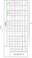
偏移灵敏度信息是指,对各种偏移值探测方法的针对各异常模式的灵敏度进行体系整理而得到的信息。在使用的偏移值探测方法的数量是N、异常模式的数量是M的情况下,偏移灵敏度信息被保持为N×M矩阵数据。偏移灵敏度信息的n行m列的数据表示第n个偏移值探测方法算法(偏移值探测方法(n))针对第m个异常模式(异常模式(m))的灵敏度。灵敏度的值越高,表示使用偏移值探测方法(n)的针对异常模式(m)的异常探测能力越高。异常探测能力高是指,异常探测容易这样的含义。The offset sensitivity information refers to information obtained by organizing the sensitivity to each abnormal mode of various offset value detection methods. In the case where the number of offset value detection methods used is N and the number of abnormal patterns is M, the offset sensitivity information is held as N×M matrix data. Data in n rows and m columns of the offset sensitivity information indicates the sensitivity of the nth offset value detection method algorithm (offset value detection method (n)) to the mth abnormal pattern (abnormal pattern (m)). The higher the value of the sensitivity, the higher the anomaly detection capability for the anomaly pattern (m) using the offset value detection method (n). High abnormality detection capability means that abnormality detection is easy.
偏移灵敏度信息被保持为N×M矩阵数据。因此,图8的步骤S303的处理中的作为偏移灵敏度信息的第j个异常模式的异常模式(j)是指偏移灵敏度信息的第j列数据。因此,异常模式(j)是包含作为偏移值探测方法的数量的N个要素的列矢量数据。关于异常模式(j),按照与偏移倾向信息相同的偏移值探测方法的顺序(比较顺序)排列灵敏度。Offset sensitivity information is held as N×M matrix data. Therefore, the abnormal pattern (j) which is the j-th abnormal pattern of the offset sensitivity information in the processing of step S303 in FIG. 8 refers to the j-th column data of the offset sensitivity information. Therefore, the abnormal pattern (j) is column vector data including N elements as the number of offset value detection methods. Regarding the abnormal pattern (j), the sensitivities are arranged in the same order (comparison order) of the offset value detection method as the offset tendency information.
异常模式既可以是基于物理现象的数据的偏移方式,也可以是单纯地可能作为数值列数据发生的偏移方式。The abnormal pattern may be a data deviation form based on a physical phenomenon, or may simply be a deviation form that may occur as numerical sequence data.
例如,如果是前者,则是信号传送路径的劣化所引起的噪声重叠,如果是后者,则是时间序列数据的振幅增大变化。如果判明作为物理现象发生什么样的故障,并且其在数据中作为什么样的特征表现,则通过将该信息整理到偏移灵敏度信息,从而在实际上发生了该异常的情况下能够容易地推测异常原因。另一方面,即使在无法辨识出物理现象的情况下,也能够推测异常模式,所以能够使异常或者故障的原因辨析以及原因缩小容易。For example, if it is the former, it is due to noise superimposition due to degradation of the signal transmission path, and if it is the latter, it is the amplitude increase and change of the time-series data. If it is known what kind of failure has occurred as a physical phenomenon and what kind of feature it appears in the data, by organizing this information into offset sensitivity information, it can be easily estimated that the abnormality has actually occurred. Abnormal reason. On the other hand, even when a physical phenomenon cannot be recognized, an abnormal mode can be estimated, so that identification and narrowing down of the cause of an abnormality or failure can be facilitated.
另外,使用者可任意地选择要选择的偏移值探测方法以及希望探测的异常模式的信息保持方法。一般,将针对设备动作(物理现象)的感测数据可能发生的所有异常模式、以及能够探测可能发生的异常模式的至少1个异常模式的所有偏移值探测方法的组合保持于偏移灵敏度信息。由此,能够针对所有异常模式进行异常探测,并且还能够执行异常模式的推测。在此,关于确定的异常模式针对确定的偏移值探测方法的灵敏度,既可以采用针对过去数据应用了确定的偏移值探测方法时的探测精度的实际值(真阳性率或者适合率等),也可以由使用者任意地设定。In addition, the user can arbitrarily select the offset value detection method to be selected and the information retention method of the abnormal pattern desired to be detected. In general, a combination of all abnormal patterns that may occur in the sensing data of the device operation (physical phenomenon) and all offset value detection methods that can detect at least one abnormal pattern that may occur is held in the offset sensitivity information . Thereby, abnormality detection can be performed for all abnormality patterns, and the estimation of abnormality patterns can also be performed. Here, regarding the sensitivity of the determined abnormal pattern to the determined offset value detection method, the actual value of the detection accuracy (true positive rate or fit rate, etc.) when the determined offset value detection method is applied to the past data can be used. , can also be set arbitrarily by the user.
另外,在针对对象设备的工作数据事先判明发生什么样的异常模式的情况下,也可以从事先准备的所有异常模式和所有偏移值探测方法的组合中仅抽出所需最小限的组合,并重新编成偏移感知表。由此,能够高效地执行异常探测。In addition, when it is known in advance what kind of abnormality pattern has occurred with respect to the operation data of the target device, only the required minimum combination may be extracted from combinations of all abnormality patterns and all offset value detection methods prepared in advance, and Reprogrammed offset-aware tables. Thereby, abnormality detection can be performed efficiently.
另外,在对象设备100中发生某种异常的情况下,不限于由于单个部位处的单独原因产生的单一异常。反而在多数的情况下,多个异常重叠而作为1个异常模式表现的情况较多。因此,设想与由于单一的原因产生的单一的异常模式的所有组合相应量的异常模式的变化。即,在将单一的异常模式的数量设想P个模式的情况下,需要设想最大2P个模式的异常。In addition, in the case where a certain abnormality occurs in the
图9至图12示出偏移灵敏度信息的信息保持方法的例子。9 to 12 show examples of information retention methods of offset sensitivity information.
如图9所示,针对偏移值探测方法(n)和异常模式(m)的灵敏度的表现有对灵敏度的好坏进行二值表现的二值表现方式(方式1)、和如图10至图12所示用[0,1]的实数对灵敏度的好坏进行等级表现的等级表现方式。As shown in Figure 9, for the performance of the sensitivity of the offset value detection method (n) and the abnormal mode (m), there are binary representations (mode 1) in which the sensitivity is good or bad, and as shown in Figure 10 to FIG. 12 shows a gradation expression method in which sensitivity is graded using real numbers [0, 1].
关于等级表现方式,有如图9所示用[0,1]的实数分别表现N×M矩阵的各数据的方式2、如图10所示针对每个异常模式(N×M矩阵的列方向)以使合计值成为1的方式进行标准化的方式3、以及如图11所示针对每个偏移值探测方法(N×M矩阵的行方向)以使合计值成为1的方式进行标准化的方式4。换言之,方式2是将针对偏移值探测方法(n)和异常模式(m)的灵敏度独立地保持的形式。方式3是针对各异常模式表现各偏移值探测方法的灵敏度优劣的方式。方式4是针对各偏移值探测方法表现各异常模式的灵敏度优劣的方式。使用者可任意地对选择哪一个方式进行选择。Regarding the level expression mode, there is a
此外,在此,用[0,1]的实数进行等级表现,但实数可取的值范围不限于[0,1],只要是某个基准范围即可。在基准范围是[0,基准值]的情况下,方式3、4以使合计值成为基准值的方式进行标准化即可。In addition, here, a real number of [0, 1] is used for rank expression, but the value range that a real number can take is not limited to [0, 1], as long as it is a certain reference range. When the reference range is [0, reference value],
参照图13,说明实施方式1所涉及的学习处理。The learning process according to
学习处理是进行各偏移值探测方法的模型学习和参数最佳化的至少任意一个的处理。学习处理例如以每1年这样的长期间隔非定期地执行。The learning process is a process of performing at least one of model learning and parameter optimization for each offset value detection method. The learning process is performed irregularly at long-term intervals such as every one year.
在步骤S401中,过去数据取得部241取得积蓄于过去数据存储部261的过去的工作数据作为学习数据。过去数据取得部241将取得的学习数据写入到主存储装置203。In step S401 , the past
接下来,在步骤S402至步骤S407中,将模型学习和参数最佳化的至少任意一个的处理,反复执行偏移值探测方法的数量N次。Next, in step S402 to step S407 , at least any one of model learning and parameter optimization is repeatedly executed for the number of offset value detection methods N times.
在步骤S402中,学习部242将计数器i初始化为1。在步骤S403中,学习部242抽出偏移值探测方法(i)的当前模型和当前参数的至少任意一个。在步骤S404中,学习部242从主存储装置203读出学习数据,通过学习数据进行模型学习和参数最佳化的至少任意一个。在步骤S405中,学习部242在步骤S404中进行了模型学习的情况下,用学习后的模型更新探测算法存储部262的模型。学习部242在步骤S404中进行了参数最佳化的情况下,用最佳化的参数更新探测算法存储部262的参数。在步骤S406中,学习部242对计数器i的值加上1。在步骤S407中,学习部242判定计数器i的值是否为偏移值探测方法的数量N以下。In step S402 , the
学习部242在计数器i的值是偏移值探测方法的数量N以下的情况下,使处理返回到步骤S403,进行关于接下来的偏移值探测方法的处理。另一方面,探测处理部223在计数器i的值大于偏移值探测方法的数量N的情况下,结束处理。When the value of the counter i is equal to or smaller than the number N of offset value detection methods, the
执行学习处理的频度还对异常探测精度造成影响。如果达到使用者要求的异常探测精度,则无需执行学习处理。因此,例如,也可以在异常探测装置200的导入初始,以某种程度高频度地更新模型,而在更新某种程度而提高了精度之后,停止更新。The frequency at which learning processing is performed also has an influence on abnormality detection accuracy. If the abnormality detection accuracy required by the user is achieved, there is no need to perform learning processing. Therefore, for example, at the beginning of introduction of the
另外,关于是否需要模型学习以及是否需要参数最佳化,针对选择的每个偏移值探测方法而不同的情况较多。因此,有时无需关于所有偏移值探测方法一并进行模型学习以及参数最佳化。在该情况下,也可以仅将确定的偏移值探测方法作为对象,执行学习处理。Also, the need for model learning and the need for parameter optimization often differ for each selected offset value detection method. Therefore, it may not be necessary to perform model learning and parameter optimization collectively for all offset value detection methods. In this case, it is also possible to execute the learning process only for the determined offset value detection method.
参照图14,说明实施方式1所涉及的偏移灵敏度信息生成处理。Referring to FIG. 14 , the offset sensitivity information generation process according to
偏移灵敏度信息生成处理是生成在异常确定处理(图5的步骤S103)中使用的偏移灵敏度信息的处理。偏移灵敏度信息生成处理需要在异常确定处理执行前至少执行1次。偏移灵敏度信息生成处理与学习处理同样地,以例如每1年这样的长期间隔非定期地执行。The offset sensitivity information generation process is a process for generating offset sensitivity information used in the abnormality identification process (step S103 in FIG. 5 ). The offset sensitivity information generation process needs to be executed at least once before the abnormality determination process is executed. Similar to the learning process, the offset sensitivity information generation process is performed irregularly at long-term intervals such as every one year.
在步骤S501中,信息生成部251选择作为对象的偏移值探测方法。在步骤S502中,信息生成部251选择作为对象的异常模式。在步骤S503中,信息生成部251在偏移灵敏度信息中的、与在步骤S501中选择的探测方法和在步骤S502中选择的异常模式对应的栏中设定数据,生成新的偏移灵敏度信息。在步骤S504中,信息积蓄部252通过在步骤S503中生成的偏移灵敏度信息,更新存储于偏移灵敏度信息存储部263的偏移灵敏度信息。In step S501 , the information generation unit 251 selects a target offset value detection method. In step S502 , the information generation unit 251 selects an abnormality pattern to be targeted. In step S503, the information generation unit 251 sets data in the column corresponding to the detection method selected in step S501 and the abnormal mode selected in step S502 in the offset sensitivity information, and generates new offset sensitivity information. . In step S504 , the
所使用的偏移值探测方法以及所设想的异常模式的组合在异常探测装置200的使用过程中也能够任意地变更。但是,在变更偏移灵敏度信息的情况下,需要再次执行偏移灵敏度信息生成处理以及学习处理。The combination of the used offset value detection method and assumed abnormality mode can also be changed arbitrarily during use of the
***实施方式1的效果******Effect of
如以上所述,实施方式1所涉及的异常探测装置200针对每个异常模式,计算偏移灵敏度信息和偏移倾向信息的类似度。由此,能够适当地探测异常,并且能够易于确定发生什么样的异常。As described above, the
实施方式1所涉及的异常探测装置200有效利用作为对各种偏移值探测方法针对各异常模式的灵敏度进行体系整理而得到的关系表的偏移灵敏度信息,实现异常探测和异常模式推测。由此,不仅能够实现如使用偏移值探测方法的已有的异常探测的正常或者异常的二值判定,而且连发生什么样的异常的解析也能够实现。只要将异常模式与对象设备的故障模式唯一地关联起来,则故障部位的确定也能够容易地执行。The
另外,仅通过单纯地使用偏移值探测方法,存在关于某个异常模式无法探测的可能性。相对于此,实施方式1所涉及的异常探测装置200通过关于所有异常模式事先在偏移灵敏度信息中网罗,能够减少针对所有异常的探测遗漏。In addition, there is a possibility that a certain abnormal pattern cannot be detected by simply using the offset value detection method. In contrast, the
另外,实施方式1所涉及的异常探测装置200无需针对每个对象设备100事先定制模型就能够应用。因此,针对无法查明物理模型的复杂的设备和作为黑盒的其它公司设备也能够期待异常探测的效果。In addition, the
***其它结构******Other structures***
<变形例1><
在实施方式1中,工作数据收集部11、工作数据发送部12、工作数据取得部21、偏移倾向计算部22、异常探测部23、参数学习部24、偏移灵敏度信息生成部25、结果接收部31、以及结果输出部32的各部分的功能用软件实现。但是,作为变形例1,上述各部分的功能也可以用硬件实现。关于该变形例1,说明与实施方式1不同的点。In
参照图15,说明变形例1所涉及的异常探测系统1的硬件结构。Referring to FIG. 15 , the hardware configuration of an
在上述各部分的功能用硬件实现的情况下,对象设备100代替运算装置104和主存储装置105而具备电子电路107。另外,异常探测装置200代替运算装置202和主存储装置203而具备电子电路205。状态监视装置300代替运算装置302和主存储装置303而具备电子电路305。In the case where the functions of the above-mentioned respective parts are realized by hardware, the
电子电路107是实现工作数据收集部11以及工作数据发送部12的功能、和主存储装置105的功能的专用电路。电子电路205是实现工作数据取得部21、偏移倾向计算部22、异常探测部23、参数学习部24以及偏移灵敏度信息生成部25的功能、和主存储装置203的功能的专用电路。电子电路305是实现结果接收部31以及结果输出部32的功能、和主存储装置303的功能的专用电路。The
作为电子电路107、205、305,设想单一电路、复合电路、程序化的处理器、并行程序化的处理器、逻辑IC、GA(Gate Array,门阵列)、ASIC(Application Specific IntegratedCircuit,专用集成电路)、FPGA(Field-Programmable Gate Array,现场可编程门阵列)。As the
既可以用1个电子电路107、205、305实现上述各部分的功能,也可以将上述各部分的功能分散到多个电子电路107、205、305来实现。The functions of the above-mentioned parts may be realized by one
<变形例2><
作为变形例2,也可以将一部分的功能构成要素用硬件实现,其它功能构成要素用软件实现。As
将运算装置104、202、302、主存储装置105、203、303以及电子电路107、205、305称为处理电路。即,上述各部分的功能通过处理电路实现。The
实施方式2.
实施方式2在异常探测装置200被分成3个装置这点上与实施方式1不同。在实施方式2中,说明该不同的点,关于相同点省略说明。
参照图16,说明实施方式2所涉及的异常探测系统1的硬件结构。此外,在图16中,省略对象设备100以及状态监视装置300的结构。Referring to FIG. 16 , the hardware configuration of the
异常探测系统1在代替异常探测装置200而具备探测装置500、学习装置600以及数据库装置700这点上与图1所示的异常探测系统1不同。探测装置500、学习装置600以及数据库装置700既可以是有实体的服务器,也可以由云构成。The
探测装置500具备通信装置501、运算装置502以及主存储装置503。学习装置600具备通信装置601、运算装置602以及主存储装置603。数据库装置700具备通信装置701、运算装置702、主存储装置703以及外部存储装置704。The
参照图17,说明实施方式2所涉及的探测装置500、学习装置600以及数据库装置700的功能结构。Referring to FIG. 17 , the functional configurations of the
作为功能构成要素,探测装置500具备工作数据取得部21、偏移倾向计算部22以及异常探测部23。作为功能构成要素,学习装置600具备参数学习部24和偏移灵敏度信息生成部25。作为功能构成要素,数据库装置700具备存储部26。As functional components, the
即,在实施方式2中,图3所示的异常探测装置200被分成执行异常探测处理的探测装置500、执行学习处理及偏移灵敏度信息生成处理的学习装置600、以及积蓄数据的数据库装置700。That is, in
通过形成实施方式2所涉及的结构,能够独立地执行异常探测处理、和学习处理以及偏移灵敏度信息生成处理。因此,容易担保通过在线处理执行的异常探测处理的执行速度。With the configuration according to
实施方式3.
在进行异常探测处理的功能设置于对象设备100这点上,实施方式3与实施方式1、2不同。在实施方式3中,说明该不同的点,关于相同点省略说明。
参照图18,说明实施方式3所涉及的异常探测系统1的硬件结构。Referring to FIG. 18 , the hardware configuration of the
异常探测系统1在未具备探测装置500这点上与图16所示的异常探测系统1不同。The
参照图19,说明实施方式3所涉及的对象设备100的功能结构。Referring to FIG. 19 , the functional configuration of the
作为功能构成要素,对象设备100具备探测装置500具备的工作数据取得部21、偏移倾向计算部22以及异常探测部23这点上与图2所示的对象设备100不同。The
即,在实施方式3中,为由对象设备100执行异常探测处理的结构。That is, in
通过形成实施方式3所涉及的结构,能够通过边缘计算来处理异常探测处理。由此,无需以持续监视等为目的始终不中断地执行工作数据这样的数据的发送接收,而能够将持续通信仅限定为异常判定结果和异常模式推测结果的发送。因此,能够节省网络400的通信量。With the configuration according to
此外,在实施方式3中,说明将实施方式2所涉及的异常探测系统1的结构变形而得到的结构。但是,还能够使实施方式1所涉及的异常探测系统1的结构发生变形。In addition, in
Claims (11)
Applications Claiming Priority (1)
| Application Number | Priority Date | Filing Date | Title |
|---|---|---|---|
| PCT/JP2018/022709 WO2019239542A1 (en) | 2018-06-14 | 2018-06-14 | Abnormality sensing apparatus, abnormality sensing method, and abnormality sensing program |
Publications (2)
| Publication Number | Publication Date |
|---|---|
| CN112272763A CN112272763A (en) | 2021-01-26 |
| CN112272763B true CN112272763B (en) | 2023-05-19 |
Family
ID=65037116
Family Applications (1)
| Application Number | Title | Priority Date | Filing Date |
|---|---|---|---|
| CN201880094472.4A Active CN112272763B (en) | 2018-06-14 | 2018-06-14 | Abnormality detection device, abnormality detection method, and computer-readable storage medium |
Country Status (5)
| Country | Link |
|---|---|
| US (1) | US11657121B2 (en) |
| EP (1) | EP3795975B1 (en) |
| JP (1) | JP6456580B1 (en) |
| CN (1) | CN112272763B (en) |
| WO (1) | WO2019239542A1 (en) |
Families Citing this family (11)
| Publication number | Priority date | Publication date | Assignee | Title |
|---|---|---|---|---|
| JP2021022311A (en) * | 2019-07-30 | 2021-02-18 | 株式会社リコー | Abnormality detecting device, abnormality detecting system, and program |
| US11341682B2 (en) * | 2020-08-13 | 2022-05-24 | Argo AI, LLC | Testing and validation of a camera under electromagnetic interference |
| CN112506908B (en) * | 2020-12-10 | 2024-07-02 | 云南电网有限责任公司玉溪供电局 | A method and system for cleaning electric energy metering data |
| CN113987476B (en) * | 2021-10-26 | 2025-06-24 | 新华三信息安全技术有限公司 | A method, device, electronic device and storage medium for determining a compromised host |
| CN116224052A (en) * | 2023-03-07 | 2023-06-06 | 南方电网科学研究院有限责任公司 | Method, device and storage medium for determining switchgear failure |
| CN116879662B (en) * | 2023-09-06 | 2023-12-08 | 山东华尚电气有限公司 | Transformer fault detection method based on data analysis |
| CN116881635B (en) * | 2023-09-08 | 2023-12-05 | 北京日光旭升精细化工技术研究所 | Data management system for textile detergent equipment |
| CN116930595B (en) * | 2023-09-18 | 2023-11-24 | 法拉迪电气有限公司 | Accurate data metering method for new energy grid-connected voltage regulation |
| CN117407728B (en) * | 2023-12-15 | 2024-03-15 | 湖南南华生物技术有限公司 | Storage environment real-time monitoring method and system for stem cells |
| CN119202544B (en) * | 2024-11-26 | 2025-08-01 | 清远市凯誉工程监理有限公司 | Energy-saving and environment-friendly detection method and system for green building |
| CN120730348B (en) * | 2025-08-22 | 2025-11-14 | 中科信创技术有限公司 | An automatic fault prediction method and system for base station operation and maintenance |
Family Cites Families (38)
| Publication number | Priority date | Publication date | Assignee | Title |
|---|---|---|---|---|
| DE69000749T2 (en) * | 1989-03-13 | 1993-04-29 | Westinghouse Electric Corp | AUTOMATIC ORBITAL ANALYSIS WITH THE APPLICATION OF A NEURON NETWORK. |
| JPH04121622A (en) | 1990-09-13 | 1992-04-22 | Hitachi Ltd | Plant operation supporting method and device as well as data display method |
| US6092029A (en) * | 1998-02-19 | 2000-07-18 | Bently Nevada Corporation | Method and apparatus for diagnosing and controlling rotating stall and surge in rotating machinery |
| JP3068091B1 (en) | 1999-06-02 | 2000-07-24 | 核燃料サイクル開発機構 | Fault diagnosis device |
| US20160026915A1 (en) * | 2001-01-05 | 2016-01-28 | In-Depth Test Llc | Methods and Apparatus for Data Analysis |
| JP4250552B2 (en) * | 2004-03-03 | 2009-04-08 | 株式会社東芝 | Manufacturing apparatus management system, manufacturing apparatus management method, and program |
| JP2005345154A (en) | 2004-05-31 | 2005-12-15 | Kyushu Electric Power Co Inc | Abnormal sign detection method and apparatus |
| US20090030753A1 (en) * | 2007-07-27 | 2009-01-29 | General Electric Company | Anomaly Aggregation method |
| JP5048625B2 (en) | 2008-10-09 | 2012-10-17 | 株式会社日立製作所 | Anomaly detection method and system |
| JP5301310B2 (en) | 2009-02-17 | 2013-09-25 | 株式会社日立製作所 | Anomaly detection method and anomaly detection system |
| JP5363927B2 (en) | 2009-09-07 | 2013-12-11 | 株式会社日立製作所 | Abnormality detection / diagnosis method, abnormality detection / diagnosis system, and abnormality detection / diagnosis program |
| JP5461136B2 (en) | 2009-09-30 | 2014-04-02 | 三菱重工業株式会社 | Plant diagnostic method and diagnostic apparatus |
| JP2011145846A (en) | 2010-01-14 | 2011-07-28 | Hitachi Ltd | Anomaly detection method, anomaly detection system and anomaly detection program |
| JP5454671B2 (en) * | 2010-02-26 | 2014-03-26 | 株式会社日立製作所 | Failure cause diagnosis system and method |
| JP5439265B2 (en) | 2010-04-20 | 2014-03-12 | 株式会社日立製作所 | Abnormality detection / diagnosis method, abnormality detection / diagnosis system, and abnormality detection / diagnosis program |
| US20130268288A1 (en) * | 2010-06-28 | 2013-10-10 | Nec Corporation | Device, method, and program for extracting abnormal event from medical information using feedback information |
| JP5501903B2 (en) | 2010-09-07 | 2014-05-28 | 株式会社日立製作所 | Anomaly detection method and system |
| JP5132746B2 (en) | 2010-09-30 | 2013-01-30 | 中国電力株式会社 | Operational abnormality detection device and operational abnormality detection method |
| JP2012155361A (en) | 2011-01-21 | 2012-08-16 | Toshiba Corp | Process monitoring device |
| JP5868216B2 (en) | 2012-02-27 | 2016-02-24 | 三菱電機株式会社 | Clustering apparatus and clustering program |
| US9850422B2 (en) | 2013-03-07 | 2017-12-26 | Prostim Labs, Llc | Hydrocarbon-based fracturing fluid composition, system, and method |
| US20160127402A1 (en) | 2014-11-04 | 2016-05-05 | Patternex, Inc. | Method and apparatus for identifying and detecting threats to an enterprise or e-commerce system |
| US9904893B2 (en) | 2013-04-02 | 2018-02-27 | Patternex, Inc. | Method and system for training a big data machine to defend |
| JP5530019B1 (en) | 2013-11-01 | 2014-06-25 | 株式会社日立パワーソリューションズ | Abnormal sign detection system and abnormality sign detection method |
| JP6216242B2 (en) | 2013-12-13 | 2017-10-18 | 株式会社日立ハイテクノロジーズ | Anomaly detection method and apparatus |
| JP6143667B2 (en) | 2013-12-27 | 2017-06-07 | 三菱重工業株式会社 | Prediction system, monitoring system, operation support system, gas turbine equipment, and prediction method |
| CN104089774B (en) * | 2014-07-25 | 2016-05-25 | 北京工业大学 | A kind of gear failure diagnosing method based on the parallel orthogonal coupling of multiword allusion quotation |
| US10271802B2 (en) | 2014-08-12 | 2019-04-30 | Carestream Health, Inc. | Digital x-ray imaging apparatus and method |
| WO2016116961A1 (en) * | 2015-01-21 | 2016-07-28 | 三菱電機株式会社 | Information processing device and information processing method |
| US20160343180A1 (en) * | 2015-05-19 | 2016-11-24 | GM Global Technology Operations LLC | Automobiles, diagnostic systems, and methods for generating diagnostic data for automobiles |
| JP6472327B2 (en) | 2015-05-26 | 2019-02-20 | 株式会社日立パワーソリューションズ | Abnormal sign diagnostic apparatus and abnormal sign diagnostic method |
| JP6523815B2 (en) | 2015-06-22 | 2019-06-05 | 株式会社日立製作所 | Plant diagnostic device and plant diagnostic method |
| JP6647824B2 (en) * | 2015-09-25 | 2020-02-14 | 三菱重工業株式会社 | Error diagnosis system and error diagnosis method |
| JP6573838B2 (en) * | 2016-02-10 | 2019-09-11 | 株式会社神戸製鋼所 | Anomaly detection system for rotating machines |
| JP6605357B2 (en) | 2016-02-29 | 2019-11-13 | 株式会社日立製作所 | Anomaly detection apparatus, anomaly detection system and method |
| JP6890382B2 (en) | 2016-05-23 | 2021-06-18 | ルネサスエレクトロニクス株式会社 | Production system |
| JP6772963B2 (en) * | 2017-06-05 | 2020-10-21 | トヨタ自動車株式会社 | Abnormality diagnosis device and abnormality diagnosis method |
| CN107644229A (en) * | 2017-08-31 | 2018-01-30 | 浙江工业大学 | Indoor anomaly detection method based on multi-sensor information fusion |
-
2018
- 2018-06-14 CN CN201880094472.4A patent/CN112272763B/en active Active
- 2018-06-14 EP EP18922746.5A patent/EP3795975B1/en active Active
- 2018-06-14 JP JP2018555298A patent/JP6456580B1/en active Active
- 2018-06-14 WO PCT/JP2018/022709 patent/WO2019239542A1/en not_active Ceased
-
2020
- 2020-10-23 US US17/078,371 patent/US11657121B2/en active Active
Also Published As
| Publication number | Publication date |
|---|---|
| US20210042585A1 (en) | 2021-02-11 |
| US11657121B2 (en) | 2023-05-23 |
| WO2019239542A1 (en) | 2019-12-19 |
| EP3795975A4 (en) | 2021-09-15 |
| EP3795975B1 (en) | 2023-08-02 |
| JP6456580B1 (en) | 2019-01-23 |
| JPWO2019239542A1 (en) | 2020-06-25 |
| EP3795975A1 (en) | 2021-03-24 |
| CN112272763A (en) | 2021-01-26 |
Similar Documents
| Publication | Publication Date | Title |
|---|---|---|
| CN112272763B (en) | Abnormality detection device, abnormality detection method, and computer-readable storage medium | |
| Steurtewagen et al. | Adding interpretability to predictive maintenance by machine learning on sensor data | |
| CN111459700A (en) | Method and apparatus for diagnosing device failure, diagnostic device, and storage medium | |
| US20160110651A1 (en) | Method of Sequential Kernel Regression Modeling for Forecasting and Prognostics | |
| US20130024166A1 (en) | Monitoring System Using Kernel Regression Modeling with Pattern Sequences | |
| US20130024415A1 (en) | Monitoring Method Using Kernel Regression Modeling With Pattern Sequences | |
| US20160110655A1 (en) | System of Sequential Kernel Regression Modeling for Forecasting and Prognostics | |
| US11747035B2 (en) | Pipeline for continuous improvement of an HVAC health monitoring system combining rules and anomaly detection | |
| US20200143292A1 (en) | Signature enhancement for deviation measurement-based classification of a detected anomaly in an industrial asset | |
| JP2009289262A (en) | System and method for advanced condition monitoring of asset system | |
| US11640459B2 (en) | Abnormality detection device | |
| KR102212022B1 (en) | Method of automatically determining condition of hydro turbine in hydroelectric power plant and system for the same | |
| EP4423582B1 (en) | System, apparatus and method for monitoring condition of an asset in technical installation | |
| JP6915693B2 (en) | System analysis method, system analyzer, and program | |
| CN119416113A (en) | A method and system for monitoring energy equipment health based on big data | |
| CN117043771A (en) | Anomaly detection based on causal graph representing anomaly causal relationships | |
| Toosi et al. | Method for detecting aging related failures of process sensors via noise signal measurement | |
| Lu et al. | Integration of wavelet decomposition and artificial neural network for failure prognosis of reciprocating compressors | |
| JP2022082277A (en) | Detection program, detection device, and detection method | |
| Mishra et al. | Hybrid models for rotating machinery diagnosis and prognosis: estimation of remaining useful life | |
| CN113646786A (en) | Signal selection device, learning device, signal selection method, and program | |
| US11320813B2 (en) | Industrial asset temporal anomaly detection with fault variable ranking | |
| JP6973445B2 (en) | Display method, display device, and program | |
| US10372719B2 (en) | Episode mining device, method and non-transitory computer readable medium of the same | |
| Chhabria et al. | Predictive maintenance using machine learning on industrial water pumps |
Legal Events
| Date | Code | Title | Description |
|---|---|---|---|
| PB01 | Publication | ||
| PB01 | Publication | ||
| SE01 | Entry into force of request for substantive examination | ||
| SE01 | Entry into force of request for substantive examination | ||
| GR01 | Patent grant | ||
| GR01 | Patent grant |