CN112272620A - Systems and methods for automated operation and handling of automated trucks and tractor-trailers - Google Patents
Systems and methods for automated operation and handling of automated trucks and tractor-trailers Download PDFInfo
- Publication number
- CN112272620A CN112272620A CN201980027012.4A CN201980027012A CN112272620A CN 112272620 A CN112272620 A CN 112272620A CN 201980027012 A CN201980027012 A CN 201980027012A CN 112272620 A CN112272620 A CN 112272620A
- Authority
- CN
- China
- Prior art keywords
- trailer
- truck
- yard
- pneumatic
- autonomous
- Prior art date
- Legal status (The legal status is an assumption and is not a legal conclusion. Google has not performed a legal analysis and makes no representation as to the accuracy of the status listed.)
- Pending
Links
Images


Classifications
-
- B—PERFORMING OPERATIONS; TRANSPORTING
- B65—CONVEYING; PACKING; STORING; HANDLING THIN OR FILAMENTARY MATERIAL
- B65G—TRANSPORT OR STORAGE DEVICES, e.g. CONVEYORS FOR LOADING OR TIPPING, SHOP CONVEYOR SYSTEMS OR PNEUMATIC TUBE CONVEYORS
- B65G69/00—Auxiliary measures taken, or devices used, in connection with loading or unloading
- B65G69/003—Restraining movement of a vehicle at a loading station using means not being part of the vehicle
- B65G69/005—Restraining movement of a vehicle at a loading station using means not being part of the vehicle the means engaging at least one wheel of the vehicle
-
- B—PERFORMING OPERATIONS; TRANSPORTING
- B60—VEHICLES IN GENERAL
- B60W—CONJOINT CONTROL OF VEHICLE SUB-UNITS OF DIFFERENT TYPE OR DIFFERENT FUNCTION; CONTROL SYSTEMS SPECIALLY ADAPTED FOR HYBRID VEHICLES; ROAD VEHICLE DRIVE CONTROL SYSTEMS FOR PURPOSES NOT RELATED TO THE CONTROL OF A PARTICULAR SUB-UNIT
- B60W60/00—Drive control systems specially adapted for autonomous road vehicles
- B60W60/001—Planning or execution of driving tasks
- B60W60/0025—Planning or execution of driving tasks specially adapted for specific operations
-
- B—PERFORMING OPERATIONS; TRANSPORTING
- B25—HAND TOOLS; PORTABLE POWER-DRIVEN TOOLS; MANIPULATORS
- B25J—MANIPULATORS; CHAMBERS PROVIDED WITH MANIPULATION DEVICES
- B25J9/00—Programme-controlled manipulators
- B25J9/16—Programme controls
- B25J9/1679—Programme controls characterised by the tasks executed
-
- B—PERFORMING OPERATIONS; TRANSPORTING
- B60—VEHICLES IN GENERAL
- B60D—VEHICLE CONNECTIONS
- B60D1/00—Traction couplings; Hitches; Draw-gear; Towing devices
- B60D1/24—Traction couplings; Hitches; Draw-gear; Towing devices characterised by arrangements for particular functions
- B60D1/26—Traction couplings; Hitches; Draw-gear; Towing devices characterised by arrangements for particular functions for remote control, e.g. for releasing
-
- B—PERFORMING OPERATIONS; TRANSPORTING
- B60—VEHICLES IN GENERAL
- B60D—VEHICLE CONNECTIONS
- B60D1/00—Traction couplings; Hitches; Draw-gear; Towing devices
- B60D1/24—Traction couplings; Hitches; Draw-gear; Towing devices characterised by arrangements for particular functions
- B60D1/36—Traction couplings; Hitches; Draw-gear; Towing devices characterised by arrangements for particular functions for facilitating connection, e.g. hitch catchers, visual guide means, signalling aids
-
- B—PERFORMING OPERATIONS; TRANSPORTING
- B60—VEHICLES IN GENERAL
- B60D—VEHICLE CONNECTIONS
- B60D1/00—Traction couplings; Hitches; Draw-gear; Towing devices
- B60D1/58—Auxiliary devices
- B60D1/62—Auxiliary devices involving supply lines, electric circuits, or the like
-
- B—PERFORMING OPERATIONS; TRANSPORTING
- B60—VEHICLES IN GENERAL
- B60D—VEHICLE CONNECTIONS
- B60D1/00—Traction couplings; Hitches; Draw-gear; Towing devices
- B60D1/58—Auxiliary devices
- B60D1/62—Auxiliary devices involving supply lines, electric circuits, or the like
- B60D1/64—Couplings or joints therefor
-
- B—PERFORMING OPERATIONS; TRANSPORTING
- B60—VEHICLES IN GENERAL
- B60L—PROPULSION OF ELECTRICALLY-PROPELLED VEHICLES; SUPPLYING ELECTRIC POWER FOR AUXILIARY EQUIPMENT OF ELECTRICALLY-PROPELLED VEHICLES; ELECTRODYNAMIC BRAKE SYSTEMS FOR VEHICLES IN GENERAL; MAGNETIC SUSPENSION OR LEVITATION FOR VEHICLES; MONITORING OPERATING VARIABLES OF ELECTRICALLY-PROPELLED VEHICLES; ELECTRIC SAFETY DEVICES FOR ELECTRICALLY-PROPELLED VEHICLES
- B60L53/00—Methods of charging batteries, specially adapted for electric vehicles; Charging stations or on-board charging equipment therefor; Exchange of energy storage elements in electric vehicles
- B60L53/30—Constructional details of charging stations
- B60L53/35—Means for automatic or assisted adjustment of the relative position of charging devices and vehicles
- B60L53/36—Means for automatic or assisted adjustment of the relative position of charging devices and vehicles by positioning the vehicle
-
- B—PERFORMING OPERATIONS; TRANSPORTING
- B60—VEHICLES IN GENERAL
- B60L—PROPULSION OF ELECTRICALLY-PROPELLED VEHICLES; SUPPLYING ELECTRIC POWER FOR AUXILIARY EQUIPMENT OF ELECTRICALLY-PROPELLED VEHICLES; ELECTRODYNAMIC BRAKE SYSTEMS FOR VEHICLES IN GENERAL; MAGNETIC SUSPENSION OR LEVITATION FOR VEHICLES; MONITORING OPERATING VARIABLES OF ELECTRICALLY-PROPELLED VEHICLES; ELECTRIC SAFETY DEVICES FOR ELECTRICALLY-PROPELLED VEHICLES
- B60L58/00—Methods or circuit arrangements for monitoring or controlling batteries or fuel cells, specially adapted for electric vehicles
- B60L58/10—Methods or circuit arrangements for monitoring or controlling batteries or fuel cells, specially adapted for electric vehicles for monitoring or controlling batteries
- B60L58/12—Methods or circuit arrangements for monitoring or controlling batteries or fuel cells, specially adapted for electric vehicles for monitoring or controlling batteries responding to state of charge [SoC]
-
- B—PERFORMING OPERATIONS; TRANSPORTING
- B60—VEHICLES IN GENERAL
- B60R—VEHICLES, VEHICLE FITTINGS, OR VEHICLE PARTS, NOT OTHERWISE PROVIDED FOR
- B60R1/00—Optical viewing arrangements; Real-time viewing arrangements for drivers or passengers using optical image capturing systems, e.g. cameras or video systems specially adapted for use in or on vehicles
- B60R1/002—Optical viewing arrangements; Real-time viewing arrangements for drivers or passengers using optical image capturing systems, e.g. cameras or video systems specially adapted for use in or on vehicles specially adapted for covering the peripheral part of the vehicle, e.g. for viewing tyres, bumpers or the like
- B60R1/003—Optical viewing arrangements; Real-time viewing arrangements for drivers or passengers using optical image capturing systems, e.g. cameras or video systems specially adapted for use in or on vehicles specially adapted for covering the peripheral part of the vehicle, e.g. for viewing tyres, bumpers or the like for viewing trailer hitches
-
- B—PERFORMING OPERATIONS; TRANSPORTING
- B60—VEHICLES IN GENERAL
- B60R—VEHICLES, VEHICLE FITTINGS, OR VEHICLE PARTS, NOT OTHERWISE PROVIDED FOR
- B60R25/00—Fittings or systems for preventing or indicating unauthorised use or theft of vehicles
- B60R25/01—Fittings or systems for preventing or indicating unauthorised use or theft of vehicles operating on vehicle systems or fittings, e.g. on doors, seats or windscreens
- B60R25/04—Fittings or systems for preventing or indicating unauthorised use or theft of vehicles operating on vehicle systems or fittings, e.g. on doors, seats or windscreens operating on the propulsion system, e.g. engine or drive motor
-
- B—PERFORMING OPERATIONS; TRANSPORTING
- B60—VEHICLES IN GENERAL
- B60R—VEHICLES, VEHICLE FITTINGS, OR VEHICLE PARTS, NOT OTHERWISE PROVIDED FOR
- B60R25/00—Fittings or systems for preventing or indicating unauthorised use or theft of vehicles
- B60R25/10—Fittings or systems for preventing or indicating unauthorised use or theft of vehicles actuating a signalling device
- B60R25/102—Fittings or systems for preventing or indicating unauthorised use or theft of vehicles actuating a signalling device a signal being sent to a remote location, e.g. a radio signal being transmitted to a police station, a security company or the owner
-
- B—PERFORMING OPERATIONS; TRANSPORTING
- B60—VEHICLES IN GENERAL
- B60R—VEHICLES, VEHICLE FITTINGS, OR VEHICLE PARTS, NOT OTHERWISE PROVIDED FOR
- B60R25/00—Fittings or systems for preventing or indicating unauthorised use or theft of vehicles
- B60R25/20—Means to switch the anti-theft system on or off
- B60R25/23—Means to switch the anti-theft system on or off using manual input of alphanumerical codes
-
- B—PERFORMING OPERATIONS; TRANSPORTING
- B60—VEHICLES IN GENERAL
- B60R—VEHICLES, VEHICLE FITTINGS, OR VEHICLE PARTS, NOT OTHERWISE PROVIDED FOR
- B60R25/00—Fittings or systems for preventing or indicating unauthorised use or theft of vehicles
- B60R25/20—Means to switch the anti-theft system on or off
- B60R25/25—Means to switch the anti-theft system on or off using biometry
-
- B—PERFORMING OPERATIONS; TRANSPORTING
- B62—LAND VEHICLES FOR TRAVELLING OTHERWISE THAN ON RAILS
- B62D—MOTOR VEHICLES; TRAILERS
- B62D13/00—Steering specially adapted for trailers
- B62D13/06—Steering specially adapted for trailers for backing a normally drawn trailer
-
- B—PERFORMING OPERATIONS; TRANSPORTING
- B62—LAND VEHICLES FOR TRAVELLING OTHERWISE THAN ON RAILS
- B62D—MOTOR VEHICLES; TRAILERS
- B62D15/00—Steering not otherwise provided for
- B62D15/02—Steering position indicators ; Steering position determination; Steering aids
- B62D15/027—Parking aids, e.g. instruction means
- B62D15/0285—Parking performed automatically
-
- B—PERFORMING OPERATIONS; TRANSPORTING
- B62—LAND VEHICLES FOR TRAVELLING OTHERWISE THAN ON RAILS
- B62D—MOTOR VEHICLES; TRAILERS
- B62D33/00—Superstructures for load-carrying vehicles
- B62D33/02—Platforms; Open load compartments
- B62D33/0222—Connecting elements between stanchions, e.g. roof supporting elements, stiffeners
-
- B—PERFORMING OPERATIONS; TRANSPORTING
- B62—LAND VEHICLES FOR TRAVELLING OTHERWISE THAN ON RAILS
- B62D—MOTOR VEHICLES; TRAILERS
- B62D53/00—Tractor-trailer combinations; Road trains
- B62D53/04—Tractor-trailer combinations; Road trains comprising a vehicle carrying an essential part of the other vehicle's load by having supporting means for the front or rear part of the other vehicle
- B62D53/08—Fifth wheel traction couplings
- B62D53/0807—Fifth wheel traction couplings adjustable coupling saddles mounted on sub-frames; Mounting plates therefor
- B62D53/0821—Lifting saddles, i.e. to lift the trailer front
-
- B—PERFORMING OPERATIONS; TRANSPORTING
- B62—LAND VEHICLES FOR TRAVELLING OTHERWISE THAN ON RAILS
- B62D—MOTOR VEHICLES; TRAILERS
- B62D53/00—Tractor-trailer combinations; Road trains
- B62D53/04—Tractor-trailer combinations; Road trains comprising a vehicle carrying an essential part of the other vehicle's load by having supporting means for the front or rear part of the other vehicle
- B62D53/08—Fifth wheel traction couplings
- B62D53/12—Fifth wheel traction couplings engaging automatically
- B62D53/125—Fifth wheel traction couplings engaging automatically with simultaneous coupling of the service lines
-
- B—PERFORMING OPERATIONS; TRANSPORTING
- B65—CONVEYING; PACKING; STORING; HANDLING THIN OR FILAMENTARY MATERIAL
- B65G—TRANSPORT OR STORAGE DEVICES, e.g. CONVEYORS FOR LOADING OR TIPPING, SHOP CONVEYOR SYSTEMS OR PNEUMATIC TUBE CONVEYORS
- B65G69/00—Auxiliary measures taken, or devices used, in connection with loading or unloading
- B65G69/003—Restraining movement of a vehicle at a loading station using means not being part of the vehicle
-
- B—PERFORMING OPERATIONS; TRANSPORTING
- B65—CONVEYING; PACKING; STORING; HANDLING THIN OR FILAMENTARY MATERIAL
- B65G—TRANSPORT OR STORAGE DEVICES, e.g. CONVEYORS FOR LOADING OR TIPPING, SHOP CONVEYOR SYSTEMS OR PNEUMATIC TUBE CONVEYORS
- B65G69/00—Auxiliary measures taken, or devices used, in connection with loading or unloading
- B65G69/28—Loading ramps; Loading docks
- B65G69/287—Constructional features of deck or surround
- B65G69/2876—Safety or protection means, e.g. skirts
- B65G69/2882—Safety or protection means, e.g. skirts operated by detectors or sensors
-
- E—FIXED CONSTRUCTIONS
- E05—LOCKS; KEYS; WINDOW OR DOOR FITTINGS; SAFES
- E05B—LOCKS; ACCESSORIES THEREFOR; HANDCUFFS
- E05B81/00—Power-actuated vehicle locks
- E05B81/54—Electrical circuits
-
- E—FIXED CONSTRUCTIONS
- E05—LOCKS; KEYS; WINDOW OR DOOR FITTINGS; SAFES
- E05C—BOLTS OR FASTENING DEVICES FOR WINGS, SPECIALLY FOR DOORS OR WINDOWS
- E05C17/00—Devices for holding wings open; Devices for limiting opening of wings or for holding wings open by a movable member extending between frame and wing; Braking devices, stops or buffers, combined therewith
- E05C17/02—Devices for holding wings open; Devices for limiting opening of wings or for holding wings open by a movable member extending between frame and wing; Braking devices, stops or buffers, combined therewith by mechanical means
-
- G—PHYSICS
- G05—CONTROLLING; REGULATING
- G05D—SYSTEMS FOR CONTROLLING OR REGULATING NON-ELECTRIC VARIABLES
- G05D1/00—Control of position, course, altitude or attitude of land, water, air or space vehicles, e.g. using automatic pilots
- G05D1/02—Control of position or course in two dimensions
- G05D1/021—Control of position or course in two dimensions specially adapted to land vehicles
- G05D1/0212—Control of position or course in two dimensions specially adapted to land vehicles with means for defining a desired trajectory
- G05D1/0225—Control of position or course in two dimensions specially adapted to land vehicles with means for defining a desired trajectory involving docking at a fixed facility, e.g. base station or loading bay
-
- G—PHYSICS
- G05—CONTROLLING; REGULATING
- G05D—SYSTEMS FOR CONTROLLING OR REGULATING NON-ELECTRIC VARIABLES
- G05D1/00—Control of position, course, altitude or attitude of land, water, air or space vehicles, e.g. using automatic pilots
- G05D1/02—Control of position or course in two dimensions
- G05D1/021—Control of position or course in two dimensions specially adapted to land vehicles
- G05D1/0231—Control of position or course in two dimensions specially adapted to land vehicles using optical position detecting means
-
- G—PHYSICS
- G05—CONTROLLING; REGULATING
- G05D—SYSTEMS FOR CONTROLLING OR REGULATING NON-ELECTRIC VARIABLES
- G05D1/00—Control of position, course, altitude or attitude of land, water, air or space vehicles, e.g. using automatic pilots
- G05D1/02—Control of position or course in two dimensions
- G05D1/021—Control of position or course in two dimensions specially adapted to land vehicles
- G05D1/0276—Control of position or course in two dimensions specially adapted to land vehicles using signals provided by a source external to the vehicle
-
- G—PHYSICS
- G05—CONTROLLING; REGULATING
- G05D—SYSTEMS FOR CONTROLLING OR REGULATING NON-ELECTRIC VARIABLES
- G05D1/00—Control of position, course, altitude or attitude of land, water, air or space vehicles, e.g. using automatic pilots
- G05D1/20—Control system inputs
- G05D1/24—Arrangements for determining position or orientation
- G05D1/247—Arrangements for determining position or orientation using signals provided by artificial sources external to the vehicle, e.g. navigation beacons
- G05D1/249—Arrangements for determining position or orientation using signals provided by artificial sources external to the vehicle, e.g. navigation beacons from positioning sensors located off-board the vehicle, e.g. from cameras
-
- G—PHYSICS
- G05—CONTROLLING; REGULATING
- G05D—SYSTEMS FOR CONTROLLING OR REGULATING NON-ELECTRIC VARIABLES
- G05D1/00—Control of position, course, altitude or attitude of land, water, air or space vehicles, e.g. using automatic pilots
- G05D1/60—Intended control result
- G05D1/656—Interaction with payloads or external entities
- G05D1/661—Docking at a base station
-
- G—PHYSICS
- G05—CONTROLLING; REGULATING
- G05D—SYSTEMS FOR CONTROLLING OR REGULATING NON-ELECTRIC VARIABLES
- G05D1/00—Control of position, course, altitude or attitude of land, water, air or space vehicles, e.g. using automatic pilots
- G05D1/80—Arrangements for reacting to or preventing system or operator failure
- G05D1/81—Handing over between on-board automatic and on-board manual control
-
- B—PERFORMING OPERATIONS; TRANSPORTING
- B60—VEHICLES IN GENERAL
- B60L—PROPULSION OF ELECTRICALLY-PROPELLED VEHICLES; SUPPLYING ELECTRIC POWER FOR AUXILIARY EQUIPMENT OF ELECTRICALLY-PROPELLED VEHICLES; ELECTRODYNAMIC BRAKE SYSTEMS FOR VEHICLES IN GENERAL; MAGNETIC SUSPENSION OR LEVITATION FOR VEHICLES; MONITORING OPERATING VARIABLES OF ELECTRICALLY-PROPELLED VEHICLES; ELECTRIC SAFETY DEVICES FOR ELECTRICALLY-PROPELLED VEHICLES
- B60L2200/00—Type of vehicles
- B60L2200/36—Vehicles designed to transport cargo, e.g. trucks
-
- B—PERFORMING OPERATIONS; TRANSPORTING
- B60—VEHICLES IN GENERAL
- B60W—CONJOINT CONTROL OF VEHICLE SUB-UNITS OF DIFFERENT TYPE OR DIFFERENT FUNCTION; CONTROL SYSTEMS SPECIALLY ADAPTED FOR HYBRID VEHICLES; ROAD VEHICLE DRIVE CONTROL SYSTEMS FOR PURPOSES NOT RELATED TO THE CONTROL OF A PARTICULAR SUB-UNIT
- B60W50/00—Details of control systems for road vehicle drive control not related to the control of a particular sub-unit, e.g. process diagnostic or vehicle driver interfaces
- B60W2050/0062—Adapting control system settings
- B60W2050/007—Switching between manual and automatic parameter input, and vice versa
-
- B—PERFORMING OPERATIONS; TRANSPORTING
- B62—LAND VEHICLES FOR TRAVELLING OTHERWISE THAN ON RAILS
- B62D—MOTOR VEHICLES; TRAILERS
- B62D63/00—Motor vehicles or trailers not otherwise provided for
- B62D63/06—Trailers
- B62D63/08—Component parts or accessories
-
- E—FIXED CONSTRUCTIONS
- E05—LOCKS; KEYS; WINDOW OR DOOR FITTINGS; SAFES
- E05Y—INDEXING SCHEME ASSOCIATED WITH SUBCLASSES E05D AND E05F, RELATING TO CONSTRUCTION ELEMENTS, ELECTRIC CONTROL, POWER SUPPLY, POWER SIGNAL OR TRANSMISSION, USER INTERFACES, MOUNTING OR COUPLING, DETAILS, ACCESSORIES, AUXILIARY OPERATIONS NOT OTHERWISE PROVIDED FOR, APPLICATION THEREOF
- E05Y2900/00—Application of doors, windows, wings or fittings thereof
- E05Y2900/50—Application of doors, windows, wings or fittings thereof for vehicles
- E05Y2900/516—Application of doors, windows, wings or fittings thereof for vehicles for trucks or trailers
-
- E—FIXED CONSTRUCTIONS
- E05—LOCKS; KEYS; WINDOW OR DOOR FITTINGS; SAFES
- E05Y—INDEXING SCHEME ASSOCIATED WITH SUBCLASSES E05D AND E05F, RELATING TO CONSTRUCTION ELEMENTS, ELECTRIC CONTROL, POWER SUPPLY, POWER SIGNAL OR TRANSMISSION, USER INTERFACES, MOUNTING OR COUPLING, DETAILS, ACCESSORIES, AUXILIARY OPERATIONS NOT OTHERWISE PROVIDED FOR, APPLICATION THEREOF
- E05Y2900/00—Application of doors, windows, wings or fittings thereof
- E05Y2900/50—Application of doors, windows, wings or fittings thereof for vehicles
- E05Y2900/53—Type of wing
- E05Y2900/531—Doors
-
- Y—GENERAL TAGGING OF NEW TECHNOLOGICAL DEVELOPMENTS; GENERAL TAGGING OF CROSS-SECTIONAL TECHNOLOGIES SPANNING OVER SEVERAL SECTIONS OF THE IPC; TECHNICAL SUBJECTS COVERED BY FORMER USPC CROSS-REFERENCE ART COLLECTIONS [XRACs] AND DIGESTS
- Y02—TECHNOLOGIES OR APPLICATIONS FOR MITIGATION OR ADAPTATION AGAINST CLIMATE CHANGE
- Y02T—CLIMATE CHANGE MITIGATION TECHNOLOGIES RELATED TO TRANSPORTATION
- Y02T10/00—Road transport of goods or passengers
- Y02T10/60—Other road transportation technologies with climate change mitigation effect
- Y02T10/70—Energy storage systems for electromobility, e.g. batteries
-
- Y—GENERAL TAGGING OF NEW TECHNOLOGICAL DEVELOPMENTS; GENERAL TAGGING OF CROSS-SECTIONAL TECHNOLOGIES SPANNING OVER SEVERAL SECTIONS OF THE IPC; TECHNICAL SUBJECTS COVERED BY FORMER USPC CROSS-REFERENCE ART COLLECTIONS [XRACs] AND DIGESTS
- Y02—TECHNOLOGIES OR APPLICATIONS FOR MITIGATION OR ADAPTATION AGAINST CLIMATE CHANGE
- Y02T—CLIMATE CHANGE MITIGATION TECHNOLOGIES RELATED TO TRANSPORTATION
- Y02T10/00—Road transport of goods or passengers
- Y02T10/60—Other road transportation technologies with climate change mitigation effect
- Y02T10/7072—Electromobility specific charging systems or methods for batteries, ultracapacitors, supercapacitors or double-layer capacitors
-
- Y—GENERAL TAGGING OF NEW TECHNOLOGICAL DEVELOPMENTS; GENERAL TAGGING OF CROSS-SECTIONAL TECHNOLOGIES SPANNING OVER SEVERAL SECTIONS OF THE IPC; TECHNICAL SUBJECTS COVERED BY FORMER USPC CROSS-REFERENCE ART COLLECTIONS [XRACs] AND DIGESTS
- Y02—TECHNOLOGIES OR APPLICATIONS FOR MITIGATION OR ADAPTATION AGAINST CLIMATE CHANGE
- Y02T—CLIMATE CHANGE MITIGATION TECHNOLOGIES RELATED TO TRANSPORTATION
- Y02T90/00—Enabling technologies or technologies with a potential or indirect contribution to GHG emissions mitigation
- Y02T90/10—Technologies relating to charging of electric vehicles
- Y02T90/12—Electric charging stations
-
- Y—GENERAL TAGGING OF NEW TECHNOLOGICAL DEVELOPMENTS; GENERAL TAGGING OF CROSS-SECTIONAL TECHNOLOGIES SPANNING OVER SEVERAL SECTIONS OF THE IPC; TECHNICAL SUBJECTS COVERED BY FORMER USPC CROSS-REFERENCE ART COLLECTIONS [XRACs] AND DIGESTS
- Y02—TECHNOLOGIES OR APPLICATIONS FOR MITIGATION OR ADAPTATION AGAINST CLIMATE CHANGE
- Y02T—CLIMATE CHANGE MITIGATION TECHNOLOGIES RELATED TO TRANSPORTATION
- Y02T90/00—Enabling technologies or technologies with a potential or indirect contribution to GHG emissions mitigation
- Y02T90/10—Technologies relating to charging of electric vehicles
- Y02T90/14—Plug-in electric vehicles
Landscapes
- Engineering & Computer Science (AREA)
- Mechanical Engineering (AREA)
- Transportation (AREA)
- Physics & Mathematics (AREA)
- Automation & Control Theory (AREA)
- General Physics & Mathematics (AREA)
- Aviation & Aerospace Engineering (AREA)
- Remote Sensing (AREA)
- Radar, Positioning & Navigation (AREA)
- Combustion & Propulsion (AREA)
- Chemical & Material Sciences (AREA)
- Power Engineering (AREA)
- Human Computer Interaction (AREA)
- Robotics (AREA)
- Sustainable Energy (AREA)
- Sustainable Development (AREA)
- Life Sciences & Earth Sciences (AREA)
- Multimedia (AREA)
- Electromagnetism (AREA)
- Manipulator (AREA)
- Business, Economics & Management (AREA)
- Health & Medical Sciences (AREA)
- Artificial Intelligence (AREA)
- Evolutionary Computation (AREA)
- Game Theory and Decision Science (AREA)
- Medical Informatics (AREA)
- Control Of Position, Course, Altitude, Or Attitude Of Moving Bodies (AREA)
- Control Of Driving Devices And Active Controlling Of Vehicle (AREA)
Abstract
A system and method for operating an Autonomous Vehicle (AV) yard truck in a yard environment is provided. The processor facilitates automatic movement of the AV yard trucks and connection and disconnection of trailers within the yard. A plurality of sensors are interconnected with the processor that sense terrain and objects in the yard and assist in automatic connection to or disconnection from the trailer. The server is wirelessly interconnected with the processor and tracks the movement of the AV yard trucks around the yard and determines the location of the connected and disconnected trailers. When the door station approaches the trailer, the door station unlocks/opens the trailer door and secures the trailer door in the open position by a clamp or the like. The system also calculates the height of the trailer and/or whether the trailer's landing gear is on the ground and interoperates with the fifth wheel to change the height, also confirms whether the dock is safe to allow manual control by the user, and determines the optimal charging time. A back-up sensor/safety automated immobilizer and intermodal container organization is also provided.
Description
Technical Field
The present invention relates to autonomous vehicles, and more particularly to autonomous trucks and trailers therefor, for example, for handling cargo within or between transportation, production or other storage facilities.
Background
Trucks are an important component in modern commerce. Trucks utilize their large interior space to transport materials and goods across continents. These goods are loaded and unloaded at various facilities of factories, harbors, distributors, retailers, end users, and the like. Large over-the-road (OTR) trucks usually consist of a tractor (tractor) or cab unit (cab unit) and a separate detachable trailer, which is detachably connected to the cab by a hitch system consisting of a so-called fifth wheel and a king pin (kingpin). More specifically, a kingpin is formed along a front end of a bottom of the trailer, and the cab includes a fifth wheel including a pad and a receiving slot for the kingpin. Since it is necessary to negotiate curves on the road, the kingpin rides in a slot in the fifth wheel in a manner that allows the trailer to rotate axially relative to the cab when connected. The cab provides power (e.g., via an electric generator, a pneumatic pressure source, etc.) to drive itself and the attached trailer. Thus, a plurality of removable connections are formed between the cab and the trailer for delivering electrical power and pneumatic pressure. The air pressure is usually used in conjunction with the cab's own (separate) brake system for operating the emergency and service brakes. The electrical power provides power for interior lighting, exterior lights and running lights, landing gear motors (if any), and the like.
Throughout the modern land-based era, connection of electrical and pneumatic lines, lifting of landing gear, operation of trailer rear swing doors (swing doors), and inspection of vehicles are all accomplished manually by the driver. For example, when it is desired to couple the cab and trailer, after backing up to the trailer to couple the truck fifth wheel to the trailer kingpin, the driver is required to leave the cab to accomplish all of these operations. More specifically, the driver must roll up the undercarriage to drop the kingpin into full engagement with the fifth wheel and climb to the rear of the cab chassis, grasp a set of retractable hoses and cables (carrying air and electricity) from the rear of the cab by hand and secure them to the corresponding attachment assemblies on the front of the trailer body. When disconnecting the trailer from the cab, the process is reversed. That is, the operator must climb up and disconnect the hoses/cables, place them in place, and then rock the landing gear to raise the kingpin out of engagement with the fifth wheel. Assuming that the trailer is to be unloaded (e.g. after reversing into a loading dock), the driver needs to walk to the rear of the trailer to unlock the trailer's side-hung doors, rotate them back 270 degrees, and then (typically) secure each door to the side of the trailer. For different types of trailers, the rear door may be rolled up (rather than flat-opened) and/or other methods may be used to accomplish access to the cargo. Other facilities, such as loading dock alarm systems, stops to prevent accidental rolling of trailers, and locking mechanisms to lock trailers to a dock, require manual operation and monitoring to ensure proper function and safety. When the truck and the trailer are backed, a great blind spot is formed due to the large length, width and height of the truck and the trailer, and many similar potential safety hazards exist.
Truck transport has a further challenge in intermodal businesses that use yard trucks to transport containers between various modes of transport. More specifically, in a rail yard, containers must be moved between railcars and trailers in a particular sequence and direction (front to back orientation when the doors are behind). Likewise, the order and direction are important when working in quay yards where containers are unloaded from ships.
Over the years, many solutions have been proposed to automate one or more of the above processes, thereby reducing the driver's labor. However, no matter how effective these solutions are theoretically, the truck industry still relies on the above-described manual methods to connect and disconnect the trailer and tractor/cab.
With the advent of autonomous vehicles, further automation of a variety of functions that have been traditionally or manually operated for convenience has been desired.
Disclosure of Invention
The present invention overcomes the disadvantages of the prior art by providing a system and method for connecting and disconnecting a trailer from a truck cab (tractor) that enhances the overall automation of the process and reduces the need for manual intervention. The system and method are particularly well suited for use in an autonomous transport environment, such as a shipping yard, port, manufacturing center, distribution center, and/or complex warehouse, where the operating range and routes of transport vehicles are limited and the transport vehicles enter and exit the facility at high densities. Land based cabs or trucks (which may be powered by diesel, gasoline, compressed gas, other internal combustion fuels, and/or plug-in charged electric and/or fuel/electric hybrid arrangements) are typically used to pull such trailers from and dispatch such trailers to other respective sites. A cab or truck (referred to as a "yard truck") within the facility may be powered by electricity or other desirable (e.g., internal combustion) fuel source, a clean-burning fuel being a non-limiting example in various embodiments.
Substantial automated operation of yard trucks (referred to herein as "autonomous vehicles" or "AV" yard trucks) and other AV trucks and tractors is facilitated by implementing automation of various systems. The systems and methods herein enable such automation. As a non-limiting example, hitch operations, including the connection of brake/electrical service by truck to the trailer, are automated. In addition, opening and closing of trailer doors (e.g., swing doors) is automated. Trailer identification in the yard and navigation associated with such trailers is automated, as well as the safety mechanisms and operation of the trailers while parked and departing. The user may be controlled to enter the truck and safety tests may be performed in an automated manner-including, but not limited to, a traction test to ensure a safe hitch. Likewise, the raising of the fifth wheel and verifying that the trailer landing gear is off the ground is also automated.
In an embodiment at least the connection of the emergency brake pneumatic line is achieved by a mutually engaging connection structure consisting of a guiding structure mounted in the cab and being conical or inclined at the distal end of the manipulator or extension and a base connector at the front/front wall of the trailer body having a corresponding receiving shape and serving to centre and align the cab guiding structure so that when fully engaged the air connection between the cab and the trailer is completed and the emergency brake can be actuated (at least) by the pressure provided by the cab. In another embodiment, the guiding structure mounted on the cab may include one or more electrical connectors for closing a power circuit between the cab and the trailer. The connection arrangement may also be adapted to interconnect a service brake line between the cab and the trailer. The attachment on the trailer may be provided using a mounting plate that is removably (or permanently) attached to the front of the trailer using, for example, a clamp that engages a slot in the bottom of the trailer as the mounting plate enters the facility. Alternatively, interengaging fabrics (e.g., hook and loop, 3M Dual-Lock) may be used TM) A fastener, a magnetic sheet, a button, or the like to detachably fix the mounting plate. The board includes a dock connector and a hose having a fitting (e.g., a pneumatic fitting) adapted to engage a standard hose fitting on a trailer.
In another embodiment, a pneumatically or hydraulically expandable (telescopic) arm is fixed to a laterally movable linear actuator behind the cab of the yard truck. In addition, a second, smaller pneumatic/hydraulic piston is fixed to the base and bottom of the larger arm so that the arm can be raised and lowered. The end of the arm is a vertical pivot or wrist (for vertical alignment) with a coupling device that can be gripped (and restored)The coupling device is deployed onto a correspondingly shaped receiver on the trailer. The coupling device also has one (or more) side-mounted air hoses for transferring air pressure from the yard truck for connection to the trailer. The integrated power supply (and communication line) is paired with the air hose, driving a collar (lock) on a standard hose fitting to pair the coupling device with the receiver. Furthermore, the electrical power delivered by the coupling device may also provide power to the trailer system (as described above). To assist the arm in automatic ranging and alignment, the camera and laser ranging device are also mounted on a clamping mechanism or clamping hand. When the gripper hands deliver the coupling device (with associated air hose and electrical connections) to the receiver and a sufficient air connection is detected, the gripping state is released and the coupling device remains in the receiver and the arm is retracted to the cab taking into account trailer clearance (clearance). By using interengaging strips or sheets of fabric (e.g. technical grade hook and loop material and/or Dual-Lock) TMReclosable fasteners, or similar materials such as magnetic sheets) as a field (or permanently affixed) releasable attachment means to mount the receiver on the trailer in a preferred position in front of the trailer. The receiver is also marked with an identifying border pattern from which associated ranging/positioning software can orient and align the arm with the coupling device.
In another embodiment, instead of the extendable arm and the second piston, two additional linear actuators are mounted in a cross-over fashion on a base linear actuator that moves along the length of the truck frame. This enables the three linear actuators to move in unison in the orthogonal X, Y and Z axes. As described above, linear actuators cross-mounted on vertical linear actuators still hold a power actuated gripping device or hand.
A system and method for operating an automated driving (AV) yard truck in a yard environment is provided. The processor is used to facilitate automated movement of the autopilot yard truck and to connect and disconnect the trailers in the yard, and substantially without human control input to piggyback control of the truck. A plurality of sensors interconnected with the processor sense terrain and objects in the yard and assist in automatically connecting and disconnecting the trailers. A server and/or Yard Management System (YMS) is wirelessly interconnected with the processor for tracking movement of the autonomous yard trucks around the yard and determining locations for attaching and detaching the trailers. Illustratively, a connection mechanism connects a service line between one of the trailers and the AV yard truck when the AV yard truck is hitched (connected) with the one of the trailers; the connection mechanism disconnects the service line when the autonomous yard truck is disconnected from one of the trailers. The service lines may include at least one of an electrical line, an emergency brake pneumatic line, and a service brake pneumatic line. The connection mechanism may include a robot that connects a connector on the AV yard truck to a receiving connector on the trailer. Also, the receiving connector may include a receiver that is removably attached to the trailer by a clamping assembly, or by interengaging fabric fasteners (or other types of fastening mechanisms).
Illustratively, the processor and the server communicate with a door station to unlock and open a rear door of the trailer when proximate the door station. The door station may include a clamping mechanism that removably holds the rear door in an open position when exiting the door station.
According to an embodiment, the processor and the server are in communication with a security system installed at a platform, the security system indicating when movement of the trailer away from the platform is enabled. Upon receiving an indication of the security system, the processor and server command the truck to move. The security system includes a multi-color signal light operably connected to the server and the processor, and/or the truck includes a sensor that reads a state of the multi-color signal light. The security system may also (or alternatively) include a locking mechanism that selectively engages a portion of the trailer when the initiation of movement away from the platform is inhibited. The processor and the server may be in communication with a charge monitoring process that is based on, for each truck in the monitored group: (a) a current state of charge of the truck; (b) the location of the truck; and (c) availability of the truck to be charged to determine an optimal interval for charging the battery of the truck, and the charge monitoring process is arranged to direct the server and the processor to return the truck to a charging station to be charged. The charging station may allow manual or automatic charging of a truck, and the monitoring process is adapted to indicate a return of the truck manually or automatically by a user depending on the current charging status. The charge monitoring process may communicate with a user through a graphical user interface. Illustratively, the processor may communicate with a traction test process that automatically determines whether the trailer is hitched while the truck is being hitched to the trailer, particularly by applying power to the truck and thereby determining the load on the truck.
According to an embodiment, the processor is in communication with a sensor assembly that is oriented rearward and adapted to sense a characteristic of a visible portion of the trailer when the trailer is adjacent to or is hitched to the truck. The sensor assembly is interconnected with an altitude determination process that calculates at least one of: (a) the height of the trailer; and (b) whether the landing gear of the trailer is engaged with or disengaged from the ground. The feature may comprise at least one of a datum on the front face of the trailer and an edge on the trailer body. Illustratively, the reference may include an ID code having information encoded therein. More specifically, the ID code may include an AR tag. The height determination process is operatively connected to a fifth wheel height controller that raises and lowers the fifth wheel in response to a calculation of at least one of (a) and (b). Further, the calculation may include determining a required trailer height to provide clearance for the predetermined location.
According to an embodiment, an authentication process may be in communication with the server and the processor and receive input identification data from a user and verify the identity and authorization of the user based on the stored information to assume manual control of the truck from an autonomous driving mode. The truck may be configured with an interface to which a user enters at least one of a password, a username, and biometric information. If the authentication process determines that the user is not authorized to take manual control, then (a) alerting the server may be performed; (b) stopping the truck; and (c) returning the truck to at least one of the safe positions.
According to an embodiment, a wheel skid arrangement is also provided that engages the wheels of the trailer and moves the wheels off of the ground to allow the trailer to be hitched and moved relative to the truck. The wheel slide carriage arrangement may comprise automatic wheel brakes responsive to braking signals from the truck.
According to one embodiment, a system for automatically connecting at least one service line on a truck to a trailer is provided. The receiver on the trailer is permanently or temporarily affixed to the trailer. The receiver is interconnected with at least one of a pneumatic circuit and an electrical circuit. When the trailer approaches or is hung on the truck, the coupler is manipulated by the end effector of the robot to find and engage the receiver. A processor moves the manipulator in response to the position of the receiver, thereby aligning and engaging the coupler with the receiver to complete the electrical circuit between the truck and the trailer. The end effector may be mounted on at least one of: (a) a frame movable along at least two orthogonal axes and having rearwardly extending arms; (b) a multi-degree-of-freedom mechanical arm; and (c) a linear actuator drive arm having a rotary joint to simultaneously effect the rearward extension and height adjustment of the end effector. The linear actuator drive arm may be mounted on a laterally moving base on the truck chassis. A rotary joint attached to the end effector includes a rotary actuator for maintaining a predetermined angle in the coupler. The coupler may include an actuated quick disconnect fitting adapted to be selectively and sealingly secured to a connector in the receptacle. The actuated, quick disconnect coupling includes an electromagnetic solenoid assembly that selectively and slidably opens and allows the quick disconnect coupling to close in response to an electrical current applied thereto. A tensioned cable may be attached to the coupler and a pneumatic line may be attached to the truck brake system. The braking system may comprise at least one of a service brake and an emergency brake. An electrical connection may be provided to the coupler attached to the electrical system of the truck. Illustratively, the receiver is removably attached to the front of the trailer by at least one of interengaging fabric material, fasteners, clamps and magnets.
According to an embodiment, a retrofit kit for a trailer is provided that includes a Y-connector for at least one of a trailer pneumatic line and a trailer electrical line, the Y-connector assembly being connected to both a conventional service connector and the receiver. The Y-connector assembly is operatively connected to a venting mechanism that selectively allows venting of one of the coupler and the regular service connector. The conventional service connector includes a pneumatic fitting.
According to one embodiment, a system and method for mechanically opening a trailer rear side hung door is provided. The frame is adapted to receive the rear of the trailer adjacent thereto. The member on the frame may be movable in a plurality of degrees of freedom relative to the frame and the trailer, and the member may comprise a structure arranged to manipulate a door securing assembly on the trailer. A door opening assembly engages and swings the door after unlocking, and an interface remotely guides the frame and the door opening assembly. A door securing assembly may maintain each door in an open orientation after the trailer is moved away from the frame. Illustratively, the door opening assembly includes at least one of a robot arm assembly and a mast assembly that move vertically into and out of engagement with each of the doors and along a path from a closed position to the open orientation. The posts may be movably mounted to a slotted floor that allows each of the posts to move along a respective slot that defines the path. According to one embodiment, the door securing assembly includes an end effector operably connected to the frame, the end effector selectively applying a clip or clip-like device to the door and the side of the trailer through the rear edge of the door and the trailer in the open orientation. The interface may include: a sensor assembly to view a rear of the trailer; and a processor that causes the frame to move in response to a control command. Illustratively, the processor may comprise at least one of: (a) a human-machine-interface (HMI) control that allows a user to move the frame based on feedback received from the sensor assembly; and (b) an automatic movement process that automatically moves the frame according to a trained pattern responsive to the sensor assembly. The sensor assembly may include a camera assembly and the automated motion process includes a vision system.
According to an embodiment, a system and method of operating a truck in a yard is provided. An autonomous truck and hitched trailer responsive to the onboard processor and remote server are provided. A safety system mounted at a platform indicates when movement of the trailer away from the platform is enabled. Upon receiving the indication of the security system, the processor and server indicate that the truck is moving. The security system includes a multi-colored signal light operably connected to the server and the processor. And the truck comprises a sensor for reading the status of the multicolour signal lamp. The security system deliberately includes a locking mechanism that selectively engages a portion of the trailer when the initiation of movement away from the platform is inhibited.
In accordance with an embodiment, a system is provided for controlling charging of an electric truck in a group of trucks having onboard processors in a facility. A remote server may be provided, wherein the processor communicates with the server (or one of them) with a charge monitoring process based on, for each truck in the monitored group: (a) a current state of charge of the truck; (b) the location of the truck; and (c) availability of the truck to be charged to determine an optimal interval for charging the battery of the truck. And the charge monitoring process is arranged to direct the server and the processor to return the truck to a charging station to be charged. The charging station allows manual or automatic charging of a truck and the monitoring process is adapted to indicate the return of the truck manually or automatically by a user depending on the current charging status. Illustratively, the charge monitoring process communicates with the user through a graphical user interface.
According to one embodiment, a system and method for operating an autonomous truck with respect to a trailer is provided. A vehicle-based processor communicates with a traction test process that automatically determines whether the trailer is hitched by applying power to the truck and determining a load on the truck when the truck is hitched to the trailer.
According to an embodiment, a system and method for handling a trailer relative to a truck is provided. A processor is in communication with a sensor assembly that is oriented rearward and adapted to sense a characteristic of a visible portion of the trailer when the trailer is adjacent to or is hitched to the truck. The sensor assembly is interconnected with an altitude determination process that calculates at least one of: (a) the height of the trailer; and (b) whether the landing gear of the trailer is engaged with or disengaged from the ground. The feature may comprise at least one of a datum on the front face of the trailer and an edge on the trailer body. More specifically, the reference includes an ID code having information encoded therein, and/or an AR tag. Illustratively, the height determination process is operatively connected with a fifth wheel height controller that raises and lowers the fifth wheel in response to a calculation for at least one of (a) and (b). The calculation may include determining a required trailer height to provide clearance for the predetermined location.
According to one embodiment, a system and method for controlling user access to an autonomous truck in a facility having a server is provided. An authentication process communicates with the server and the truck's onboard processor, receives identification data input from a user, and verifies the user's identity and authorization to assume manual control of the truck from an autonomous driving mode based on the stored information. An interface may be provided on the truck to which a user enters at least one of a password, a username, and biometric information. Illustratively, if it is determined during the authentication process that the user is not authorized to take manual control, performing (a) alerting the server; (b) stopping the truck; and (c) returning the truck to at least one of the safe positions.
According to one embodiment, a system and method are provided that allow a trailer to move around a facility in a manner that does not require an interconnecting service connection between a truck and the trailer. A wheel skid arrangement engages and moves the wheels of the trailer off the ground to allow the trailer to be hitched and moved relative to the truck. The wheel slide carriage arrangement may comprise automatic wheel brakes responsive to braking signals from the truck. A pneumatic supply or other switchable power source (controlled by RF or other signals from the truck) is used to operate the brakes and/or lighting on the wheel slide gantry.
According to an embodiment, there is provided an open side hung door system and method for holding a trailer comprising a clip-like clamping device constructed and arranged to clamp an open side hung door in a curved and frictional manner relative to a side of the trailer, the clamping device being located at a rear edge of the side hung door and the side. The clamping device may define a pair of tines connected by a connection base with a gap therebetween. The gripping device may be adapted to slide over the rear edge, either automatically or manually, and/or the connection base may include structure that is selectively engaged by an end effector of the robot. Illustratively, the clamping device comprises a flexible material and defines a unitary structure between the tines and the connection base. The geometry of the tines (e.g., defined as a curve, polygon, or other shape) may be varied to improve bending, structural clearance on the door/trailer side, and/or to improve grip.
According to one embodiment, a system and method for handling a trailer using a truck without a service connection between a pneumatic brake system of the truck and a brake system of the trailer is provided. A compressed air tank is removably secured to the trailer and is connected to the braking system of the trailer. The arrangement further comprises a valve cooperating with the canister, the valve being actuated to release the brake system in dependence on a signal from the truck. Illustratively, the truck is an autonomous truck, and the signal is wirelessly transmitted from a controller of the truck. More specifically, the truck may be an autonomous vehicle yard truck and the tank may be adapted to be attached to the trailer by an OTR truck when the trailer is transported to the yard.
According to one embodiment, a system and method for identifying and locating container wells on railcars in a yard is provided, comprising: a scanner to scan the railcar based on relative motion between the railcar and the scanner and to compare a tag to stored information about the railcar. The scanner is a stationary scanner and the rail car passes relative to the scanner. The tags are Radio Frequency Identification (RFID) tags located on at least one of a front or a rear of each of the railcars. Alternatively or additionally, the scanner is part of a motion sensing system with sensors that scan the rail car. A processor receives information about the railcar from the sensing system and organizes parking locations for container carrier trailers adjacent the railcar based on the well location and orientation. Illustratively, the trailer is moved by an autonomous yard truck under the control of at least one system server. In an embodiment, a processor receives information about the railcar from the scanner and organizes parking locations for container carrier trailers adjacent to the railcar based on the well location and orientation. The trailer is moved by an autonomous yard truck under the control of at least one system server.
According to one embodiment, a system and method for locating a pneumatic joint connector at the front of a trailer is provided that includes a coarse sensing system that acquires at least one of a 2D image and a 3D image of the front and searches for image features related to the pneumatic joint. After identifying the edge in the image in front of the trailer, the coarse sensing system locates features that have a different texture or color than surrounding image features. The coarse sensing system may include a sensor located on a cab or chassis of the automated storage yard truck. A fine sensing system on an end effector of a fine robot, the fine sensing system moved by a coarse motion operation to a position adjacent to the leading position containing a candidate pneumatic joint feature. The fine sensing system may comprise a plurality of 2D imaging sensors and/or 3D imaging sensors. The fine robot may include a multi-axis robotic arm mounted on a multi-axis coarse motion mechanism. The coarse motion mechanism may include a plurality of linear actuators mounted on the autonomous yard truck that move the fine manipulator from a neutral position to a position adjacent to the pneumatic joint candidate feature. Illustratively, the coarse motion mechanism includes a piston driven articulated platform mounted on the autonomous yard truck that moves the fine manipulator from a neutral position to a position adjacent the pneumatic joint candidate feature. The fine robot may be servoed based on feedback received from the fine sensing system relative to the pneumatic joints imaged by the fine sensing system. Illustratively, the fine sensing system locates a trained feature on the pneumatic joint to determine the pose of the pneumatic joint. The feature may be at least one of an annular seal of the pneumatic fitting, a contoured edge for securing a flange of the pneumatic fitting, and a label attached to the pneumatic fitting. The tag may include a reference matrix that facilitates determining the gesture. The label may be located on a clamp that is attached to the raised element on the pneumatic fitting. The feature may include a plurality of identification areas on a gasket seal of the pneumatic fitting.
According to one embodiment, a system and method for attaching a truck-based pneumatic line connector to a pneumatic sub on a trailer using a robot with an end effector that selectively engages and releases the connector is provided, including a clamping assembly that selectively covers a ring seal of the pneumatic sub and sealingly clamps the connector to the ring seal. The clamping assembly may be at least one of an actuating clamp and a spring-loaded clamp. Illustratively, the spring-loaded clamp is normally closed and opened by the clamping action of the end effector. The actuation fixture includes one of: (a) a pair of rotating clamping members; and (b) a sliding clamping member.
According to an embodiment, a system and method are provided for attaching a truck-based pneumatic line connector to a pneumatic connection on a trailer using a robot with an end effector that selectively engages and releases the connector, comprising: a probe member including a pressure port inserted and retained in an annular seal of the pneumatic joint based on a placement motion of the end effector. The probe member may comprise one of: (a) a frusto-conical plug releasably crimped into the annular seal; and (b) a gas-filled plug that selectively engages a cavity below the annular seal of the pneumatic fitting and expands to be secured therein. The frusto-conical plug includes circumferential barbs to assist in retention against the annular seal.
According to one embodiment, a system and method are provided for attaching a truck-based pneumatic line connector to a trailer pneumatic sub on a trailer using a robot with an end effector, wherein the end effector selectively engages and releases the connector, comprising: a further pneumatic coupling secured to the trailer pneumatic coupling in a substantially conventional manner. Another pneumatic joint includes a quick disconnect (universal) joint that receives a selective connector from the end effector. The end effector carries correspondingly oppositely shaped joints to selectively connect and disconnect universal joints.
According to an embodiment, there is provided a system and method for assisting the reverse operation of a trailer hitched to an autonomous truck, comprising: an unmanned vehicle disposed relative to a rear of the trailer and imaging a space behind the trailer at least one of (a) prior to and (b) during reverse movement. The unmanned vehicle may include at least one of an Unmanned Aerial Vehicle (UAV) and an Unmanned Ground Vehicle (UGV), the unmanned ground vehicle including a mechanical vehicle having a plurality of sensor types and tracking a periphery of the trailer to locate a rear of the trailer. Illustratively, the sensor types may include a forward looking sensor and an upward looking sensor. The unmanned ground vehicle may also be adapted to travel along the top of the roof of the trailer. And a deployment mechanism lifts the unmanned ground vehicle from a position on the truck and places the unmanned ground vehicle on the roof. The unmanned ground vehicle is arranged to travel relative to a centerline of the roof. The unmanned ground vehicle includes at least one of a rail and a wheel that frictionally engages the roof.
According to an embodiment, there is provided a system and method for assisting reverse operation on a trailer hitched to an automatic truck, comprising: a movement sensor assembly mounted on a linear guide transversely mounted to the structure adjacent a parking area where a trailer is to be received. The sensor assembly provides/transmits sensor data relating to a space behind the trailer, the sensor data being employed by at least one of a facility control server of the autonomous truck and an onboard controller of the autonomous truck. The sensor assembly may include at least one of a vision system camera, a LIDAR, and a radar. Illustratively, the linear guide is mounted relative to the loading dock, and/or the linear guide may comprise at least one of a rail, a line, and a track. The sensor assembly is movable to a position in the structure where the autonomous truck is operating, and wherein the sensor assembly is constructed and arranged to provide sensor data to a plurality of autonomous trucks upon respective reverse movements in the position of the structure.
According to an embodiment, there is provided a system and method for transporting land trailers using an autonomous yard truck, comprising: a split skid bed trailer has a front portion and a pair of spaced apart rails extending rearwardly from the front portion. The front portion includes: a fifth wheel hitch for engaging the truck; and a plurality of rear wheels located on each of the rails near the rear of the skid bed trailer. The split skid bed trailer and associated wheels are interconnected with the electrical and pneumatic circuitry of the autonomous yard truck to provide braking to the skid bed rear wheels and illumination to the skid bed rear. A lifting mechanism is positioned relative to the wheels to lift the rails to move the wheels of the OTR trailer off the ground when the split skid is backed up and engages the OTR trailer. Thus, the OTR trailer may be adequately supported and moved by the split skid semi-permanently coupled to the AV yard truck. Illustratively, the rails are arranged in a variable length manner to accommodate OTR trailers of predetermined length.
In accordance with another embodiment, a system and method for transporting OTR trailers using an autonomous yard truck is provided, comprising: a pair of automatically movable skid platforms, each said skid platform adapted to engage wheel sets on opposite respective sides of said land trailer. Each of the sliding carriages is adapted to lift the wheel sets off the ground and provide braking and lighting in response to signals provided by the autonomous yard truck.
According to one embodiment, there is provided a system and method for automatically applying a jack to a trailer, comprising: a base mounted on the ground, and a rotation mechanism that rotates the jack assembly from a substantially flush orientation with the ground to an upright orientation with the jack pad facing the bottom of the trailer. A pair of telescoping jack members move in an upright direction from a retracted position below the bottom of the trailer to a deployed position engaging the bottom of the trailer.
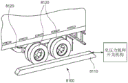
According to an embodiment, there is provided a system and method for automatically stopping a trailer, comprising: a pair of pads having a predetermined length greater than a length of a wheel set of the trailer. The mat is fixed on the ground and configured/adapted to cause the set of trailer wheels to ride onto the mat. The inflating material selectively inflates to define a plurality of contoured surfaces that support the wheels of the wheel set against rolling of the wheels. The inflated material, on the contrary, enables the wheel to roll freely when deflated. Illustratively, the inflating material defines a cross-section having a series of substantially triangular teeth of a saw tooth when inflated.
According to an embodiment, there is provided a system and method for automatically stopping a trailer, comprising: a pair of manifold housings having a predetermined length greater than a length of a wheel set of the trailer. The manifold housing is present along each of the opposite respective sides such that it is adapted to allow the wheel sets to travel between the manifold housings. A plurality of side-by-side inflatable tubes extend inwardly toward an adjacent one of the wheel sets, wherein fully extended tubes protrude through the wheels of the wheel sets to inhibit rolling of the wheel sets.
According to an embodiment, there is provided a system and method for automatically stopping a trailer, comprising: a track located below the trailer; a slider moving along the track. The lever assembly selectively moves to apply and remove interference to the set of wheels of the trailer as the slider moves the lever assembly along the track proximate the set of wheels. The lever assembly includes a pair of oppositely extending lever extensions that selectively extend the lever assembly from a width less than an interior width between the wheel sets to a width greater than the interior width. Alternatively, at least one of the lever assembly and the slide includes a rotation mechanism that rotates the lever between an elongated direction substantially parallel to the track and a transverse direction extending across a path of travel of the wheelset.
According to one embodiment, a system and method for transporting OTR trailers using an autonomous yard truck is provided. The systems and methods include a gantry system, comprising: a frame having wheels at front and rear portions thereof; and a lifting mechanism adapted to be backed to the trailer facing the underside of the trailer. The lifting mechanism is configured and arranged to lift the underside to bring the trailer out of contact with a ground surface. The drive directs the wheels to move and travel into alignment and engagement with the trailer, and the braking system and/or lighting system operate based on commands from a system controller. Illustratively, the system controller is part of at least one of an autopilot yard truck hitched to at least one of the frame and the trailer when lifted by the lift mechanism. The lifting mechanism spans the entire length of the trailer.
In accordance with another embodiment, a system and method for transporting an OTR trailer using an autonomous truck is provided, comprising: a mobile skid platform sized and arranged to deploy and travel under the underside of the land trailer and located between opposing sets of wheels adjacent the rear of the land trailer. A clamping element is engaged with each of the opposing wheel sets and is adapted to disengage the wheel sets from contact with the ground and provide braking and illumination in response to a remotely provided signal. Illustratively, the signal is provided by at least one of a system server and the autonomous truck. A tether may also be provided that selectively extends from an attachment location on the autonomous truck to the sliding carriage. The tether carries at least one of pneumatic pressure and electrical power. Additionally, the autonomous truck may be arranged to secure the skid carriage relative to a chassis of the autonomous truck when the skid carriage is in the undeployed state.
In accordance with another embodiment, a system and method for transporting an OTR trailer using an autonomous truck is provided, comprising: a pair of automatically movable sliding carriages, each adapted to engage a wheel set on opposite respective sides of the land trailer, each adapted to lift the wheel set off the ground and provide braking and lighting in response to signals provided by the autopilot yard truck. Illustratively, each of the sliding carriages includes an onboard processor and power supply deployed at a remote location for automated operation. The remote location is at least one of a facility waiting area, a location on a chassis of the autonomous truck, and a charging station. The skid platform includes sensors that allow movement and alignment relative to the OTR trailer and wheel set and provide signals to a controller. Also, the controller may be provided in at least one of the autonomous truck and a system server. A tether selectively extends from an attachment location on the autonomous truck to at least one of the sliding carriages. The tether carries at least one of pneumatic pressure and electrical power. The autonomous truck is arranged to secure the skid carriage relative to a chassis of the autonomous truck when the skid carriage is in an undeployed state.
In accordance with another embodiment, a system and method for transporting OTR trailers in a yard is provided, comprising: mechanical tractors, each of said tractors being adapted to pass under said land trailer when said land trailer is supported on the landing gear, and said tractors being engaged with the kingpin of said land trailer. The tow vehicle includes sensors that identify and locate the kingpin and the landing gear and provide signals to a controller associated with a system server, the tow vehicle provides motive power for movement and provides a vertically moving support that selectively raises the kingpin when the kingpin is engaged with the support. Illustratively, at least one of the following is also included: (a) a skid bed assembly engaged with the wheel sets on opposite respective sides of the land trailer, the skid bed assembly adapted to lift the wheel sets out of contact with the ground and provide braking and illumination in response to signals coordinated with movement of the mechanical tractor, and (b) a robotic arm mounted on the mechanical tractor that removably engages at least one of a braking pneumatic pressure connection and an electrical connection on the land trailer, thereby providing power and pneumatic pressure from a source associated with the mechanical tractor.
According to one embodiment, a system and method for determining the relative angle of a trailer with respect to a truck in the relative relationship of the truck attempting to move in reverse to hitch a trailer is provided. A space sensing device is positioned on the truck and faces rearward, the sensing device being positioned to sense a space under the underside of the trailer. A processor identifies and analyzes data points generated by the sensing device relative to at least one of a landing gear leg of the trailer and a wheel set of the trailer, and determines the relative angle therefrom. The sensing device may include a high resolution lidar device that uses a projected ring of structured light to generate points, and associated groups of points (e.g., 3D point clouds). The processor identifies a set of points/point cloud and compares the set of points to the expected shape and position of the landing gear leg. If one of the landing gear legs is blocked, the processor is adapted to estimate the position of the blocked landing gear leg to determine the relative angle. The processor is further adapted to locate and analyze the shape and position of the wheel set to achieve at least one of: (a) identifying the relative angle determined based on the landing gear leg, and (b) determining the relative angle alone when the angle of the landing gear leg cannot be analyzed or determined. The processor may be arranged to determine the position of a kingpin of the trailer.
According to one embodiment, a system and method are provided for determining the relative position of a kingpin of a trailer relative to a truck in the relative relationship of the truck attempting to move in a reverse direction for hitching to the trailer. A space sensing device is positioned on the truck and faces rearward, the sensing device being positioned to sense a space under the underside of the trailer. A processor identifies and analyzes data points (e.g., a 3D point cloud) generated by the sensing device relative to at least one of the kingpin, landing gear legs of the trailer, and wheel sets of the trailer to determine the relative position of the kingpin. Illustratively, the sensing device is a high resolution lidar device that uses a projected ring of structured light to generate a point/point cloud. The processor identifies a set of points/point clouds and compares the set of points/point clouds to expected shapes and positions of the kingpin and landing gear leg. The processor may be arranged to iteratively image with the lidar device and locate a group of points representing expected positions and provide the relative position of the kingpin in response to a confidence value above a predetermined threshold.
Drawings
The invention is described with reference to the following drawings, in which:
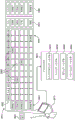
FIG. 1 is an aerial view of an exemplary transportation facility having locations for storing, loading and unloading trailers used in conjunction with an AV yard truck configuration operating within a yard provided in accordance with the systems and methods;
FIG. 2 is a perspective view of a fuel-powered AV yard truck used in conjunction with the systems and methods described herein;
FIG. 3 is a rear view of an electric AV yard truck used in conjunction with the systems and methods described herein, illustrating service connections (e.g., pneumatic braking and electrical connections);
FIG. 4 is a rear view of another electric AV yard truck showing the raised fifth wheel of the truck chassis;
FIG. 5 is a partial side view of a hitched AV yard truck and trailer showing a pneumatic connection consisting of a truck mounted probe and a trailer mounted receiver according to one embodiment;
FIG. 6 is a partial top view of the hitch AV yard truck and trailer of FIG. 5, illustrating the trailer being rotated relative to the truck at an angle such that the receiver and probe are spaced apart from each other;
FIG. 7 is a more detailed perspective view of the probe and receptacle arrangement of FIG. 5 showing the probe guided into the receptacle during connection;
FIG. 8 is an exposed side view of the probe and receiver arrangement of FIG. 5, illustrating exemplary pneumatic connections of an emergency brake circuit between an AV yard truck and a trailer;
FIG. 8A is an exposed side view of an exemplary probe and receiver arrangement similar to that of FIG. 5, including a plurality of electrical contacts for interconnecting electrical services between the AV yard truck and the receiver when the pneumatic services are connected;
FIG. 8B is an exploded perspective view of an air connecting mechanism having an actuating collar that locks a female connector (truck/coupler side) to a male connector (trailer/receiver side) in accordance with another embodiment;
8C-8E are side cross-sectional views of the mechanism of FIG. 8B, showing the connection process of connecting and locking the female connector to the male connector in the disconnected, connected and locked states, respectively;
FIG. 9 is an exemplary AV yard truck and trailer side view with a truck mounted probe and trailer mounted receiver for connecting, for example, a pneumatic emergency brake service, wherein the probe is mounted on a tensioned cable and spool assembly to allow the trailer to rotate relative to the truck, according to an embodiment;
FIG. 10 is a more detailed side cross-sectional view of a probe and receptacle arrangement including the cable and spool assembly of FIG. 9;
FIG. 11 is a rear view of an AV yard truck and trailer in a hitched configuration showing a truck mounted probe and a trailer mounted receiver for connection to, for example, a pneumatic emergency brake service, wherein the probe is mounted in a position to connect to an adjacent tensioned cable and spool assembly to allow the trailer to rotate relative to the truck, according to an embodiment;
FIG. 12 is a more detailed side cross-sectional view of a probe and receptacle arrangement including the cable and spool assembly of FIG. 11;
FIG. 13 is a partial rear view of a trailer having a frusto-conical receiver for pneumatic connection for connection with an AV yard truck, in accordance with an embodiment;
FIG. 14 is a more detailed perspective view of the tapered receiver of FIG. 13 showing interconnected bracket assemblies that allow the receiver to be selectively attached to and detached from the trailer body;
FIG. 14A is a perspective view of an exemplary receiver having interconnected pneumatic lines/air hoses that connect to existing pneumatic couplings of a trailer pneumatic line;
FIG. 15 is a perspective view of the movable clamp selectively attached to and detached from the carriage;
FIG. 16 is a partial bottom view of the trailer of FIG. 13 showing the hook or post of the bracket end inserted into the slot in the bottom of the trailer;
FIG. 17 is a perspective view of the pneumatic connection system of the AV truck and trailer showing the frusto-conical receiver attached to the trailer and the probe assembly having an inflation ring for hermetically sealing the probe and receiver;
FIG. 18 is a front view of a moveable plate for mounting one or more receivers on a trailer for connecting pneumatic and/or electrical services, the moveable plate including a pair of lever clamp brackets that engage slots in the bottom/underside of the trailer, according to an embodiment;
FIG. 19 is a side view of the plate and bracket assembly of FIG. 18;
FIG. 20 is an exploded view of the plate and bracket assembly of FIG. 18;
FIG. 21 is a bottom view of the trailer according to FIG. 18 showing various operational components of the trailer, including a plate, bracket assembly attached to the receiver;
FIG. 22 is a more detailed partial perspective view of the attached plate and bracket assembly shown in FIG. 21;
FIG. 23 is a top rear view of an improved pneumatic fitting for forming a pneumatic connection according to various embodiments;
FIG. 24 is a bottom front view of the improved pneumatic fitting of FIG. 23;
FIG. 25 is a side view of the improved pneumatic coupling of FIG. 23 secured to a conventional pneumatic coupling (e.g., on a trailer emergency brake line) by a movable thumb clamp engaged to the top of the conventional pneumatic coupling body;
FIG. 26 is a rear view of an AV yard truck illustrating a multi-axis robot assembly for connecting truck pressure or electrical connectors to a trailer receiver, in accordance with an embodiment;
fig. 26A is a partial rear view of an AV yard truck having a three axis (triple) linear actuator adapted to deliver a coupler to a receiver in accordance with an embodiment;
fig. 27 is a rear view of an AV yard truck showing the mechanical frame, telescoping arms, and end effector assembly for connecting truck pressure or electrical connectors to trailer receivers, in accordance with an embodiment;
FIG. 28 is a partial side view of a truck chassis showing a multi-axis robotic arm and end effector assembly for connecting truck pressure or electrical connectors to a trailer receiver in accordance with an embodiment;
fig. 28A is a perspective view of a robot mounted on an AV yard truck, including an arm/wrist/hand delivery mechanism with interconnected trailer pneumatic lines (air hoses) and coupling devices, according to an embodiment;
FIG. 28B is a partial side view of an exemplary AV yard truck and trailer hitched thereto having the arm/wrist/hand delivery mechanism of FIG. 28A, and a corresponding receiver mounted on the trailer;
FIG. 28C is a side view of the arm/wrist/hand delivery mechanism of FIG. 28A connected to a trailer mounted receiver;
FIG. 29 illustrates a block diagram of the general process and operational components for hitching an AV yard truck onto a trailer, including the use of a robot to connect one or more service lines, in accordance with one embodiment;
FIG. 30 is a schematic view of a door station for opening/closing a trailer door during loading and unloading within a yard environment;
FIG. 30A is a detailed view of the clamping mechanism of FIG. 30, according to an illustrative embodiment;
FIG. 31 is a perspective view of an exemplary multi-arm robot for the door station of FIG. 30;
FIG. 32 is a partial perspective view of the rear of an exemplary trailer positioned adjacent a door station including a floor base having a retractable door opening post and a frame for the trailer to enter in a reverse direction, the frame having a door unlocking and door opening securing mechanism that selectively engages a side hung door at the rear of the trailer;
FIG. 32A is an exploded perspective view of the door station of FIG. 32;
FIG. 32B is a plan view of an exemplary door capture clip for use in the open door capture mechanism of FIG. 32, which may be applied to a swing-open trailer door to hold it in an open position during transport and unloading;
FIG. 32C is a perspective view of the door securement clip and associated gripper mechanism of the door opening securement mechanism of FIG. 32, showing a state of gripping the clip;
FIG. 32D is a perspective view of the door securement clip and associated gripper mechanism of the door opening securement mechanism of FIG. 32C, shown in a state wherein the clip is released;
FIG. 32E is a partial perspective view of the exemplary trailer rear and door station of FIG. 32, showing the open door securing mechanism moved to apply a clamp to an edge of a side hung door as the open door pillar extends from the floor base to hold the door in an open position;
FIG. 32F is a partial perspective view of the exemplary trailer rear and door station of FIG. 32 showing the door opening securing mechanism applying a clamp to the edge of a side hung door as the door opening post is retracted to the floor base;
FIG. 32G is a partial perspective view of the exemplary trailer rear and door station of FIG. 32 showing the open door securing mechanism away from the edge of the swing open door with the clamp released and the vehicle door secured in a swing open position;
FIG. 33 is a rear perspective view of an exemplary AV yard truck and trailer hitched thereto depicting a camera/ranging sensor combination mounted on the rear of the yard truck for identifying and tracking unique features of the front panel of the trailer;
FIG. 33A is a diagram of the image processing stage used to extract tracking features in subsequent image frames during a reverse maneuver of an exemplary yard truck;
FIG. 33B shows an image of a trailer indicating the vertical offset of the tracking features in the image used to estimate the height difference of the trailer and hence the height of the fifth wheel landing gear off the ground;
FIG. 34 is a drawing showing a plurality of side-by-side OTR trailer fronts and an associated plurality of corresponding locations of application trailer identification numbers thereon;
FIG. 34A illustrates a plurality of discrete exemplary AR tags that may be placed on the front panel of a trailer to simplify the task of visually identifying a particular trailer using an automated computer vision system;
FIG. 34B shows a rear perspective view of an AV yard truck showing the coverage of mounted sensors to help identify trailers on both the left and right sides of the yard truck;
FIG. 34C shows a flow chart represented by a series of image boxes representing a process for sensor processing to extract a trailer identification number from the front of the trailer;
FIG. 35 shows a schematic diagram of a loading dock signaling system and corresponding signaling units according to a prior embodiment, featuring red and green lights indicating whether the trailer can be safely unloaded and/or towed away, or whether the dock is open or closed;
FIG. 36 is a schematic diagram of a dock signal system with dock communications electronics added through a wiring harness to allow use in an autonomous truck environment, according to an embodiment;
FIG. 37 is a schematic diagram of a dock signal system with a custom/dedicated dock signal unit with additional capability to interoperate with an automated system of an autonomous truck environment, according to an embodiment;
FIG. 38 is a diagram of a system and method for detecting and reporting the status of the signal unit shown in FIG. 35, for example, using a camera or equivalent sensor mounted on an AV yard truck, according to an embodiment;
FIG. 39 illustrates a block diagram of an exemplary computer system used in an electric AV yard truck environment, the computer system having a charge management and scheduling process (processor) and associated user interface for entering a desired charge time slot;
FIG. 40 is a flow chart of an exemplary traction test process used with an autonomous truck to verify proper trailer hitch;
FIG. 40A illustrates a single pull test of a portion of a multiple pull test procedure verifying proper trailer hitch;
FIG. 40B is a flow chart of an exemplary multi-pull test process including reusing the single pull test procedure of FIG. 30A to verify proper trailer hitch;
FIG. 41 is a flow chart of an exemplary mode change procedure for switching from automatic mode to driver system operation;
FIG. 42 is a schematic top view of an exemplary railcar having an RFID tag for determining a well site in an autopilot yard truck environment in accordance with an embodiment;
FIG. 43 shows a schematic top view of a train having a plurality of railcars with RFID tags for use with yard-based scanning or movement perception systems for determining well locations and sequencing therefrom;
FIG. 44 is a schematic top view of a parked train and a plurality of associated trailer parking locations identified and organized by the sensing and/or perception system of FIG. 43;
FIG. 44A is a flow diagram of a process for determining a rail car well location and a trailer parking location using the sensing system of FIG. 43, according to an embodiment;
FIG. 44B is a flow diagram of a process for determining a railcar well location and a trailer parking location using the sensing system of FIG. 43, according to one embodiment;
FIG. 45 illustrates the front of a trailer showing the proper location of the associated panels providing pneumatic brake pneumatic joint connections used in the coarse position determination of the coarse sensing assembly operation of the autonomous truck according to one embodiment;
FIG. 46 illustrates a rough position sensing assembly mounted on an autonomous truck for detecting a front feature of an adjacent trailer to position a pneumatic joint panel thereon;
FIG. 47 is a drawing showing the acquired image generated by the sensing assembly of FIG. 46 and the area therein for positioning the pneumatic joint panel;
FIG. 48 illustrates a trailer hitched to an autonomous truck chassis showing a fine position end effector mounted on the autonomous truck chassis generally in accordance with FIG. 32, with a fine sensing assembly positioned relative to the end effector to guide it onto a pneumatic joint of the trailer;
FIG. 49 is a multi-axis (e.g., three-axis) coarse positioning assembly mounted on the chassis of an autonomous truck for moving a robotic arm manipulator and associated end effector to position the end effector and a loaded truck-based pneumatic joint connector adjacent a trailer pneumatic joint panel positioned by the coarse detection system;
FIG. 50 shows an image of a trailer pneumatic joint that is used by the fine sensing system to determine pose for maneuvering the robot end effector and associated truck-based pneumatic joint connector into engagement with the trailer pneumatic joint;
FIG. 50A is a perspective view of an exemplary pneumatic joint gasket having features that enhance automatic identification, position, and orientation of the pneumatic joint gasket;
FIG. 51 illustrates a conventional trailer pneumatic joint showing the flange unique edges for pneumatic joint attitude identified by an autonomous truck and robot sensing assembly;
FIG. 52 illustrates a conventional pneumatic joint having a unique tag for identifying the attitude of the pneumatic joint by an autonomous truck manipulator sensing assembly;
FIG. 53 illustrates a fiducial-based unique identifier that may be applied to the label surface of FIG. 52;
FIG. 54 shows a schematic view of a trailer hitched to an autonomous truck chassis showing a multi-axis coarse steering system carrying a fine manipulator according to an embodiment;
FIG. 55 is a top view of the trailer and autonomous truck of FIG. 54 showing the angle of rotation of the trailer on its hitch, the coarse handling system positioning the fine robot therein so that its end effector can reach the pneumatic joint panel of the trailer;
FIG. 56 is a top view of the trailer and autonomous truck of FIG. 54, showing the trailer in another, opposite rotational angle relative to FIG. 55, with the coarse steering system positioning the fine manipulator therein so that its end effector can reach the pneumatic joint panel of the trailer;
FIG. 57 is a side view of a trailer hitched to an auto-drive truck chassis showing a multi-axis coarse steering system with a fine robot arm, wherein the robot system is mounted on a piston driven articulated platform in a stowed orientation, according to another embodiment;
FIG. 58 is a side view of the trailer and autonomous truck of FIG. 57, showing the piston-driven articulating platform in a deployed orientation on the truck chassis;
FIG. 59 is a perspective view of a multi-axis (e.g., 6-axis) fine manipulation robot arm assembly and associated end effector for manipulating truck-based trailer pneumatic joint connectors in accordance with various embodiments herein;
FIG. 60 is a partial side view of a truck-based pneumatic hitch connection that employs a clamping action in response to an associated actuator, in an open orientation relative to a trailer pneumatic hitch;
FIG. 60A is a partial side view of the truck-based pneumatic coupling connection of FIG. 60 in a closed/engaged orientation relative to the trailer pneumatic coupling;
FIG. 61 is a partial side view of a truck-based pneumatic joint connection that employs a spring-loaded, clip-like action in response to movement of a robot end effector, which is in an open orientation relative to a trailer pneumatic joint;
FIG. 61A is a partial side view of the truck-based pneumatic coupling connection of FIG. 61 in a closed/engaged orientation relative to the trailer pneumatic coupling;
FIG. 62 is a partial perspective view of a truck-based pneumatic coupling connection employing a press-fit coupling action, in an engaged/coupled orientation relative to a trailer pneumatic coupling;
FIG. 62A is a cross-sectional view taken along line 62A-62A of FIG. 48;
FIG. 63 is a cross-sectional perspective view of a truck-based pneumatic hitch connection employing an inflatable, plug-like connection in an engaged/coupled orientation relative to a trailer pneumatic hitch, whereby a robotic arm accesses the interconnect through appropriate truck-based connections and end effectors;
FIG. 64 is a perspective view of a truck-based pneumatic hitch connection having an industrial interchange connector thereon to semi-permanently attach the truck-based pneumatic hitch (using conventional swivel attachment techniques) to the pneumatic hitch of a trailer;
FIG. 65 is a partial side view of a truck-based pneumatic hitch connection employing the clamping action of a linear actuator integrated into the truck coupler in an open orientation relative to the trailer pneumatic hitch;
FIG. 66 is a partial side view of the truck-based pneumatic coupler connection of FIG. 51 in a closed/engaged orientation relative to the trailer pneumatic coupler;
67 and 67A illustrate a flow chart of a process for performing a pneumatic joint (or similar) connection between an autonomous truck and a trailer using coarse and fine sensing and maneuvering systems, according to various embodiments herein;
FIG. 68 is a partial perspective view of the rear of a trailer showing an Unmanned Aerial Vehicle (UAV) and an Unmanned Ground Vehicle (UGV) under control of an autonomous truck and/or facility system server, scanning and imaging a rear region of the vehicle for, for example, reverse operation, according to an embodiment;
FIG. 69 is a partial perspective view of an autonomous truck and trailer hitched thereto showing a deployment mechanism and associated UGV engaged with a front end of the trailer top in accordance with an embodiment;
FIG. 70 is a partial perspective view of the trailer and UGV of FIG. 69 showing the UGV acquiring sensor data from the rear of the trailer roof;
FIG. 71 is a perspective view of a split skid trailer hitched to an autonomous truck, which may receive and transport an OTR trailer without an electrical or pneumatic connection between the OTR trailer and the truck, as the split skid trailer may provide functions other than reverse sensing, according to an embodiment;
FIG. 72 is a perspective view of the split skid bed trailer and OTR trailer of FIG. 71, shown engaged for transport by an autonomous truck;
FIG. 73 is a partial perspective view of one of a pair of automated sliding gantries for engaging the wheel sets on each side of the OTR trailer so that the OTR trailer can be transported by an autonomous truck without contacting the ground, the sliding gantries providing braking, lighting and rear sensing, engaging and lifting wheel sets, in accordance with an embodiment;
FIG. 74 is a partial perspective view of the automated sliding stand and OTR trailer of FIG. 73, showing the wheels sets elevated in an engaged condition;
FIG. 74A is a side view of a single tethered mechanical skid platform used in conjunction with an autopilot yard truck to raise the rear wheel set of an exemplary trailer to avoid the need to connect brake pneumatic lines and/or electrical connections from the yard, showing a ready to engage trailer, according to an embodiment;
FIG. 74B is a top view of the skid bed and adjacent trailer of FIG. 74A, showing the location of the wheels and axles on the trailer;
FIG. 74C is a top view of the trailer of FIGS. 74A and 74B showing the skid bed engaged with the wheels of the trailer to lift off the ground;
FIG. 74D is a perspective view of one of the pair of sliding stands shown engaged with wheels on the respective side of the exemplary trailer in accordance with one embodiment;
fig. 74E is a side view of a mechanical gantry system for raising the entire bottom of an exemplary trailer in conjunction with an autonomous yard truck (not shown) or as a stand-alone autonomous transport unit, thereby avoiding the need to connect pneumatic and/or electrical connections from the yard truck, illustrating a ready-to-engage trailer, according to an embodiment;
fig. 74F is a side view of the mechanical gantry system and exemplary trailer of fig. 74E, shown engaged and prior to lifting;
fig. 74G is a side view of the mechanical gantry system and exemplary trailer of fig. 74E, shown engaged and with the trailer lifted off the ground for transport;
FIG. 74H is a side view of a mechanical tractor for raising the front kingpin of an exemplary trailer and a robotic arm on the tractor providing a connection between the tractor and trailer brake pneumatic lines and/or electrical connections, shown in a ready to engage the trailer, according to an embodiment;
FIG. 74I is a side view of the aligned tractor and trailer of FIG. 74H, shown ready to engage and raise the king pin;
FIG. 74J is a side view of the towing vehicle and trailer of FIGS. 74H and 74I with the vertical post engaged and raising the kingpin and the robotic arm engaged with a pneumatic hitch on the trailer for providing brake pneumatic and/or electrical power;
FIG. 74K is a side view of an automated tractor for raising the front kingpin of an exemplary trailer, and a breakaway skid carriage raising the rear wheels to avoid connection between the tractor and trailer brake pneumatic lines and/or electrical connections, shown in a ready to engage the trailer, in accordance with an embodiment;
FIG. 74L is a side view of the aligned tractor and trailer of FIG. 74K, shown ready to engage and raise the kingpin;
FIG. 74M is a side view of the tractor and trailer of FIGS. 74K and 74L with the vertical posts engaged and raising the kingpin and the sliding carriage assembly allowing free movement of the rear of the trailer through the associated braking and illumination provided by the sliding carriage assembly;
FIG. 74N is a perspective view of a split skid trailer with an integrated towing vehicle;
FIG. 75 is a partial perspective view of a facility mounted motion sensing system for providing images of the rear of a trailer typically towed by an autonomous truck, in accordance with an embodiment;
FIG. 76 is a partial perspective view of the trailer and associated landing gear positioned adjacent the self-presenting jack stand, shown with the jacks in a retracted position and level with the ground, according to an embodiment;
FIG. 77 is a partial perspective view of the trailer and associated landing gear positioned adjacent the self-presenting jack stand of FIG. 76, shown with the jacks in the deployed position and the jack pads facing the bottom of the trailer;
FIG. 78 is a partial perspective view of the trailer and associated landing gear positioned adjacent the self-presenting jack stands of FIG. 76, shown in an engaged position with the trailer abutting the pads and with the jacks supporting the bottom of the trailer;
FIG. 79 is a partial perspective view of a trailer and associated set of wheels parked on an inflatable, serrated, automatic stop according to an embodiment, shown in a deflated, undeployed state;
FIG. 80 is a partial perspective view of the trailer and associated wheel set of FIG. 79 with the automatic stops in an inflated, deployed state and the serrations engaging and restricting movement of the wheel set;
FIG. 81 is a partial perspective view of a trailer and associated set of wheels parked adjacent a manifold that deploys a plurality of inwardly extending inflatable tubes to provide an automatic stop assembly, shown in a deflated, undeployed state;
FIG. 82 is a partial perspective view of the trailer and associated wheel set of FIG. 81 with the automatic stop assembly in an inflated, deployed state and engaging and restricting movement of the wheel set;
FIG. 83 is a partial perspective view of a trailer and associated wheel set parked on an automatic stop assembly using a centerline rail having a sliding transverse tube/rod with relatively telescoping tubes/rods shown in an undeployed state, according to one embodiment;
FIG. 84 is a fragmentary perspective view of the trailer and associated wheel set with the telescoping tubes/rods of the automatic stop assembly of FIG. 83 relatively extended and retracted, the telescoping tubes/rods in an extended, deployed condition and ready to engage the wheel set;
FIG. 85 is a partial perspective view of the trailer and associated wheel set with the deployed tube/rod extension end of the automatic stop assembly of FIG. 83 slidingly engaging the wheel set to limit movement thereof;
FIG. 86 is a partial perspective view of a trailer and associated wheel set parked on an automatic stop assembly using a centerline rail with a sliding transverse tube/bar having a pivot mechanism on the slider to rotate the bar between an undeployed direction parallel to the rail and a deployed direction perpendicular to the rail, showing the undeployed direction, in accordance with an embodiment;
FIG. 87 is a partial perspective view of the trailer and associated wheel set with the automatic stop assembly of FIG. 86 in a rotationally deployed orientation, ready to engage the wheel set;
FIG. 88 is a partial perspective view of the trailer and associated wheel set with the deployed tube/rod of the automatic stop assembly of FIG. 87 slidingly engaging the wheel set to limit movement of the wheel set;
fig. 89 is a side view of an autonomous (e.g., yard) truck and trailer arranged to allow hitching together using a high-resolution LIDAR device mounted behind the truck and an associated process (processor) that locates and determines relative angles of the trailer (centerline) with respect to the truck;
FIG. 90 is a top view of the truck and trailer arrangement of FIG. 89, showing the trailer landing gear and wheel set position relative to the light beam pattern of the rear LIDAR device;
FIG. 91 is a top view of the LIDAR device scan area of the trailer of FIGS. 89 and 90 showing a set of points representing landing gear legs and wheels used to determine relative trailer angles;
FIG. 92 is a top view of the truck and trailer arrangement of FIGS. 89 and 90 scanned by a LIDAR device beam, wherein the trailer centerline is at almost a right angle to the central axis of the cone beam/truck centerline, with one of the trailer landing gear legs occluded;
FIG. 93 is a side view of an autonomous (e.g., yard) truck and trailer arranged to allow hitching to be achieved using a high resolution LIDAR device mounted behind the truck and an associated process (processor) that locates and positions a trailer kingpin for hitching to the truck's fifth wheel;
FIG. 94 is a top view of the truck and trailer arrangement of FIG. 93 showing trailer kingpin, landing gear and wheelset positions relative to a light beam pattern of a rear LIDAR device;
FIG. 95 is a top view of the LIDAR device scan area of the trailer of FIGS. 93 and 94 showing a set of points representing the kingpin and landing gear legs for determining the kingpin position within the vehicle/navigation coordinate space; and
fig. 96 is a flow chart of a process for identifying and determining a trailer kingpin position using a LIDAR device according to fig. 93-95.
Detailed Description
I. Overview
Fig. 1 illustrates an aerial view of an exemplary transportation facility 100 in which over-the-road (OTR) trucks (tractor-trailers) are shipped from a distance to load a trailer of cargo and return the trailer to the original location (or other location such as a warehouse). In standard operation, the OTR transport equipment is brought with the trailer to a destination guard room (or similar facility entry checkpoint) 110. The guard/attendant enters trailer information (trailer number or qr (id) code scan embedded information already present in the system, typically including trailer make/model/year/service connection location, etc.) into the facility software system, which is part of a server or other computing system 120, located off-site or wholly or partially within the facility building complexes 122, 124. The complexes 122, 124 include perimeter loading stations (located on one or more sides of the building), associated (typically overhead) cargo entrances and doors, and above-ground warehouses, all arranged in a manner well known to those skilled in the transportation, logistics, and like arts.
As shown in a simplified operational example, upon arrival of an OTR truck, the guard/attendant may instruct the driver to transport the trailer to a particular numbered parking space of a designated parking area 130 (shown here as an area in which a large number of trailers 132 are parked and side-by-side in the overall layout of the facility). Trailer data and parking status are typically updated in the company's integrated management system (YMS), which may be stored on server 120 or elsewhere.
After the driver parks the trailer in the designated parking space of the waiting area 130, he/she will disconnect the service line and ensure that the connector is in an accessible position (i.e. adjustable/sealable). If the trailer is equipped with a side hung door, the trailer door can be opened and clamped in the open position at the direction of the yard personnel.
After a certain time, the trailers (i.e., loaded) in the waiting area 130 are hitched to a yard truck/tractor (in this case an Autonomous Vehicle (AV)). When unloading a designated trailer, the AV yard truck is assigned to its marked parking space to retrieve the trailer. When the yard truck is backed to the trailer, the yard truck uses one or more installed cameras (e.g., standard or custom cameras, 2D grayscale or color pixel cameras, image sensor based cameras), and/or other associated (typically 3D/range determination) sensors (e.g., GPS receivers, radar, laser radar (LIDAR), stereo vision sensors, time-of-flight cameras, ultrasonic/laser rangefinders, etc.) to implement the following functions: (i) confirming the identity of the trailer by reading the trailer number or scanning a QR code, bar code, or other type of coded identifier; (ii) the connector (connector) of the truck is aligned with the receiver (receptacle) of the corresponding trailer. Non-limiting examples of such connectors include the connection of cab fifth wheel to trailer kingpin, pneumatic lines, and electrical wires. Optionally, during the pulling up of the AV yard truck and initial alignment with the trailer, a trailer check may also be performed using a camera mounted on the yard truck, for example to check for damage, confirm tire inflation status, and verify other safety standards.
The hitched trailer is pulled by the AV yard truck to the unloading area 140 of the facility 100. The trailer is dumped into the dock of the area with the open rear side abutting the facility entrance and cargo doors. The cargo is then unloaded from the trailer using manual and automated techniques to be placed into the facility 100. During unloading, the AV yard truck may remain attached to the trailer or may be disconnected from the trailer to perform other tasks. After unloading, the AV yard truck finally removes the trailer from the unloading area 140, or returns it to the waiting area 130, or transports it to the loading area 150 of the facility 100. A trailer with its rear side swing door (or other type of door) open is returned to the loading dock and loaded from the facility 100 using manual and/or automated techniques. The AV yard truck may again hitch the loading trailer and pull it from the loading bay 150 to the waiting bay 130 for ultimate handling by OTR trucks. At each step of this process, appropriate data tracking and management is performed using sensors on the AV yard trucks and/or other manual or automatic data collection devices (e.g., ground and/or aerial camera drones).
Having described the general techniques for handling trailers within a facility, reference is now made to fig. 2-4 for illustrating exemplary yard trucks 200 and 300 for use with the various embodiments described below. The yard trucks 200 (fig. 2) are powered by diesel or other internal combustion fuel, and the yard trucks 300, 400 (fig. 3 and 4) are powered using a suitable rechargeable battery assembly that operates in a manner well known to those skilled in the art. For the purposes of this description, the AV yard truck may be powered by rechargeable batteries, but any other power source (or combination thereof) may be used to provide mobility to the unit. Notably, each exemplary yard truck 200, 300, 400 includes at least a cab portion 210, 310, 410, respectively (which may be omitted from the fully autonomous versions); steering wheels (and other manual controls) 212, 312, 412; and a chassis 220, 320, 420 including front steering wheels 222, 422 and at least one pair of rear drive wheels 224, 324 (shown herein as a two-wheel arrangement with greater load capacity). Each chassis 220, 320, 420 further includes a so-called fifth wheel 240, 340, the fifth wheels 240, 340 (referring particularly to trucks 300, 400 in fig. 3 and 4) being arranged as horseshoe-shaped pads 342, 442 having a rearwardly facing slot 344 (fig. 3), the slot 344 being sized and arranged to receive a king pin hanger (further shown and described below) located at the bottom of a standard trailer (not shown). As shown in fig. 2, the fifth wheel 240, 340, 440 is inclined downwardly towards the rear to facilitate the hill work when the truck is backed up to the trailer. As shown in fig. 4, the fifth wheel 440 is raised by the lever arm assembly 442, thereby allowing the trailer's landing gear (when attached) to move off the ground during towing by the truck 400, as described below. The lifting mechanism of the lever arm assembly 442 or other fifth wheel may use a suitable hydraulic lifting actuator/mechanism known to those skilled in the art to cause the front end of the hitched trailer to be lifted. In this lifting direction the hitch between the truck and the trailer is fixed.
As generally described above, an AV yard truck may include various sensors that allow it to navigate in the yard and be hitched/detached to/from trailers in an automated manner that is substantially or completely free of human intervention. In addition to issuing commands to retrieve or unload trailers, without human intervention, issuing commands may also be accomplished by YMS through server 120 using wireless data transmission 160 (fig. 1) between the truck and truck (also including, for example, a suitable wireless network transceiver based on WiFi or the like).
Notably, the AV yard trucks 200, 300 and 400 of fig. 2, 3 and 4 include emergency brake pneumatic hoses 250, 350, 450 (typically red), respectively; service brake pneumatic hoses 252, 352, 452 (typically blue) and electrical lines 254, 354, 454 (typically black) which, in this example, extend from the rear side of the cab 210, 310, 410 and are suspended in a conventional (manually connected) arrangement in front of the cab side. Thus, yard personnel may be provided access during the above operations while connecting and disconnecting hoses/lines from the trailer. As shown by the dashed boxes, the AV yard trucks 200, 300, 400 include controller components 270, 370 and 470, respectively. The controllers 270, 370, 470 may reside anywhere on the truck, acceptable, or otherwise. Controllers 270, 370, 470 are interconnected with one or more sensors 274, 374, 474, respectively, which sensors 274, 374, 474 sense and measure the operating environment of the yard and provide data 160 to or obtain data 160 from the facilities (e.g., YMSs, servers 120, etc.) via transceivers. The control of the trucks 200, 300, 400 may be implemented entirely independently within the controllers 270, 370, 470, which receive the mission plan and determine the appropriate operations (e.g., start, stop, turn acceleration, brake, forward, reverse, etc.). Alternatively, the control decisions/functions may be distributed between the controller and a remote control computer (e.g., server 120) that calculates the control operations of the truck and transmits them back as data, which is operated by the truck's local control system. In general, control of truck operation may be suitably distributed between the local controllers 270, 370, 470 and the facility system server 120 according to the desired results.
Pneumatic line connection between yard truck and trailer
A. Probe and receiver assembly
A particular challenge in creating an AV yard truck and trailer system that is substantially or completely free of human intervention during ground operations is to automatically connect/disconnect hoses and wires between the truck and trailer in a reliable and accurate manner. Fig. 5-8 show a basic arrangement 500 consisting of an AV yard truck 502 and a trailer 504. Additions and/or modifications can be made to the conventional trailer arrangement to operate in an AV yard environment. The truck 502 and trailer 504 are shown as being coupled together by at least one connector (e.g., pneumatic emergency brake line) 510. When towing a truck in a yard, the yard truck usually only establishes an emergency brake connection, but additional connections to service brakes and electrical wiring, etc. are also contemplated. The connection arrangement 510 for a single pneumatic line herein comprises: a receiver assembly 520 permanently or temporarily mounted to a front portion 522 of the trailer 504; and a probe assembly 530 extending from a rear 532 of a truck cab 534. In this embodiment, the connection arrangement 510 provides a positive sealed pressurized coupling between one of the air supply pneumatic lines (e.g., emergency brakes) from the truck to the trailer. Pressure is generated on the truck side (by a pump, pressure tank, etc.) and is transferred to the components that drive the trailer brakes when activated by the truck control system 270, 370.
The receiver assembly 520 and the probe assembly 530 are frusto-conical in shape that engage one another, wherein the probe head 540 is mounted at the end of a semi-rigid hose member 542 (e.g., about 1.5-4.5 feet), and the end of the semi-rigid hose member 542 may be supported by one or more lanyards that are tall mounted to the rear of the truck cab. The conical shape is sufficient to enable connection between the probe head 540 and the receiver 520 when the truck is backed directly onto a trailer. With particular reference to fig. 8, the receiver of this embodiment is directly attached to the front 522 of the trailer 504 and includes a central bore 810, the central bore 810 extending between a side mount port 820 (which may be threaded or otherwise connected to a standard trailer pressure line) and a pressure quick disconnect (male) fitting 822. The geometry of the above-described joints is well known to those skilled in the art. The probe head 540 also includes an aperture 830, the aperture 830 being connected to an adjacent fitting 832, the adjacent fitting 832 coupling the semi-rigid hose member 542 to the probe head 540. In this embodiment, the proximal end of the semi-rigid hose member 542 is attached to a base 840, the base 840 being secured to the rear 532 of the truck cab 534. The position of the base 840 is selected to align with the receiver 520 when the trailer and truck are aligned straight fore and aft. Various mechanisms may be employed to align and guide the probe head 540 to the receiver, as described below. The base 840 also includes a side port 842, the side port 842 interconnected with the AV truck brake pressure source/circuit and selectively pressurized when the brakes are activated. The distal end of the conical probe 540 includes a quick disconnect pressure (female) connector 850, the connector 850 adapted to sealingly mate with the connector 822 of the receptacle. The probe connector 850 may be locked to the connector 822 of the receptacle when driven axially a sufficient distance from the connector of the receptacle. The connector of the receptacle may include one or more peripheral stops and appropriate internal springs, and a collar and ball bearings may be used in the construction of the probe connector to engage the stops and thereby affect the interconnection seal between the connectors 822, 850. Alternatively or additionally, pneumatic and/or electromechanical locking mechanisms may be used to lock the connectors together. Unlocking of the connectors 822, 850 during disconnection may be achieved by simply pulling the arrangement apart, thereby overcoming the locking force of the axial obstruction, activating a pneumatic and/or electromechanical unlocking mechanism or any other mechanical action that allows the mechanism to unlock. The diameter and angle of the tapered probe and tapered receiver are variable. In one embodiment, ports 812 and 842 of receiver 520 and probe 540 are connected to hoses that can be plugged directly into pneumatic lines on trailers and trucks. Alternatively, the ports 812, 842 may each be connected to a hose that each includes a conventional or modified (described below) pneumatic fitting (glad hand) connector. The pneumatic connector is permanently or temporarily (for trailers) interconnected with a standard pneumatic line pneumatic connector.
The probe 540 and the receiver 520 may be made of a variety of materials, such as durable polymers, aluminum alloys, steel, or combinations thereof. Connectors 822 and 850 may be made of brass, steel, polymer, or combinations thereof. They typically include one or more O-rings made of, for example, polyurethane or other durable elastomer. Semi-rigid hose 542 may be made of a polymer (polyethylene, polypropylene, etc.) or natural or synthetic rubber with a fiber or steel reinforced jacket.
As shown briefly in the embodiment of fig. 8A, the receptacle 860 and the stylet 870 (which operates similarly to the stylets 540 and 520 described above) may include electrical contacts, such as a plurality of axially spaced concentric rings 880, 882, 884 formed on the conical outer surface of the stylet 870, the concentric rings 880, 882, 884 contacting corresponding rings or contacts 890, 892, 894 formed on the conical inner surface of the receptacle 860 when the connector 872 (shown in phantom) of the stylet and the connector 862 (shown in phantom) of the receptacle are fully engaged. This completes the electrical connection between the trailer electrical components (lights, signals, etc.) and the switching power supply on the truck. Appropriate plugs and sockets may extend from the probes and receivers to interconnect standard truck and trailer wires. It should be noted that in alternative embodiments, a variety of alternative electrical connection arrangements may be used in conjunction with, or separate from, the pneumatic probe and receiver.
The embodiment of fig. 8B-8E illustrate a connector/coupler assembly 880 that can be selectively changed between a locked state and an unlocked state by electrical actuation. The assembly 880 is adapted to interoperate with the probe and receiver assemblies described above or other coupler and receiver arrangements in the embodiments described below. The coupler assembly 880 includes a male coupler 881, which may be part of a receiver or probe. In this embodiment, the coupler 881 includes a conventional 1/2 inch NPT thread, for example, a threaded pipe, an air line (airline) quick disconnect coupling, and one or more integral annular locking grooves 882. The groove 882 may define a semi-circular cross-sectional shape. The female component of the integral assembly 880 is adapted to releasably connect and lock to a male connector 881, which is formed as a sliding quick disconnect connector. In this embodiment, the inner sleeve 884 is sized to slide over the male connector 881 when coupled together. A set of outer rim, e.g., ball bearings 885 are located in bores 886 formed around the circumference of the sleeve 884. The ball bearings 885 of the female coupling are sized to be placed completely within the outer rim apertures 886 of the sleeve so that the male coupler can be slid onto the female coupling in an unengaged state. In this orientation, they do not need to be in mutual interference with the axis of the male coupler. These ball bearings are adapted to partially spring out of their respective holes when the male coupler is fully placed in the female fitting, thereby engaging the slot 882 and locking the coupler assembly together. Thereby forming a locking engagement. A spring 887 is located behind the inner sleeve 884. When the covered iron or steel (magnetic) sleeve 888 is fully advanced against the front shoulder 889 of the inner sleeve 884 (see figure 8E), the ball bearings 885 are forced into an engaged position. The locking bias is provided by a spring that is also supported on the rear pipe joint 891. In this position, the inner surface of the magnetic sleeve 888 is arranged to force the balls 885 inwardly against the groove 882 of the male connector. Thus, a sufficient locking is formed between the female part and the male part. As part of the female coupling, an O-ring seal 890 seals the locking arrangement to prevent air leakage (thereby forming a pressurized connection).
Notably, the outer annular (or other shaped) sleeve 892 includes an electromagnetic coil, such as a solenoid. When energized, the coil forces the magnetic sleeve 888 axially rearward (against the bias of the spring 887) and aligns the ball bearings 885 with the annular groove 893 within the front inner surface of the magnetic sleeve 888. This annular groove allows the ball bearing 885 to spring sufficiently radially outward from the bore 886 to thereby disengage from the male connector groove 882, thereby allowing the male connector to move axially relative to the female connector. This unlocked state is shown in fig. 8C and 8D.
In operation, current is delivered to outer sleeve/solenoid 892 through a relay or other switch that receives a signal from an AV yard truck controller or the like. A vehicle battery (not shown) of sufficient power may be included in the female coupler assembly. In addition, power may be supplied through the electrical system of the AV yard truck. Thereby, the axial rearward movement of the magnetic sleeve shown in fig. 8C is achieved. This position allows the ball bearings 885 to move radially inward (as shown in figure 8D) as the male connector moves axially inward relative to the inner sleeve 884. In this step, outer sleeve/solenoid 892 is still powered by the switch and battery. Once fully engaged, the switch will disconnect the battery and the spring 887 will drive the magnetic sleeve forward (since it is not biased by the magnetic solenoid). Thus, the ball bearings 885 encounter the non-recessed portion of the inner surface of the magnetic sleeve 884 and are driven radially outward into the groove 882 of the male connector, thereby forming a sealed lock as shown in fig. 8E.
B. Probe connected to reel
Fig. 9 and 10 show an arrangement 900 with a pneumatic connection 930 for use with an AV yard truck 910 and trailer 920 according to another embodiment, wherein a probe assembly 940 is attached to a reel or spool 942. It can be seen from this arrangement that during a turn (i.e., rotation of the kingpin about the dashed axis 924 about the fifth wheel 914), the front of the trailer 922 is generally away from the rear of the cab 912. This is also shown in fig. 6, where the receiver 520 is spaced a large distance from the probe 540. To address the issue of variations in spacing between the receiver 950 and the probe 940 (the embodiment of fig. 9 and 10) during rotation, and more specifically, to address positional offset between the truck and trailer, the probe 940 is mounted on a semi-rigid tube 944, i.e., without any air conduits (in this embodiment). The exemplary frusto-conical probe 940 includes a side port 1020 (fig. 10), the side port 1020 directing air to a (e.g., female) pressure connector 1030 at the proximal end of the probe. The probe side port 1020 is interconnected to the truck pressure line in a manner similar to the probe 540 described above. The connector and associated receiver 950 components are otherwise similar to fig. 5-8 and are interconnected according to similar operations. I.e., the truck is backed to the trailer and the probe 940 and receiver 950 are aligned linearly. The probe 940 is then guided to the receptacle 950 by the engagement of the respective surfaces of the frustoconical shape with one another until a positive lock is created between the associated pressure connectors. As shown in the embodiment of fig. 5-8, buckling can occur when the connectors are biased together to form a lock, while the semi-rigid tube 944 is sufficiently rigid to prevent buckling therefrom. Once locked, as the trailer 920 moves relative to the truck 910 to tension the probe 940, the cable is paid out from a spool 942 connected to the proximal end of the tube 944 to release the tension. Spool 942 may be spring loaded so that it is always held in proper tension on tubing 944 and associated probes. The hose attached to the probe-side port 1020 from the pneumatic source may be flexible (e.g., containing a spring coil as generally shown in fig. 2), or may absorb stretching and shrinking. It should be noted that the proximal end of the tube includes a (positive) frustoconical end member 1040 that mates with a (negative) frustoconical receiver 1050 on the spool 942. This assembly forms a stop for the tubing 944 when the probe is biased into the receiver 950 and ensures that the spool cable 1032 pulls the cable fully back into the spool 942 when fully retracted without forming any kinks near the bottom of the tubing 944. The spool may be configured in various ways, for example as a wrap/wound spring or as a suitable transmission configured to produce a predetermined torque over a predetermined number of revolutions (well known to those skilled in the art). The spool 942 may be electrically operated according to a common tension, paying out the cable and retracting it. In this embodiment, the spool 942 serves both as a winding device for the cable (1032) and as a base for the probe assembly 940 in a single unit. It should be noted that the spool is a commercially available component. Additionally, pressure connectors are also commercially available components, such as those used in standard pneumatic hose applications.
The embodiment of fig. 11 and 12 further details the arrangement 1100. as described above or according to another embodiment (described below), the trailer 1110 includes a receiver (not shown), and the truck 1120 includes a probe assembly 1130 adapted to removably engage the receiver as described above. The head 1132 of the probe assembly 1130 includes a side-mounted pressure port and associated hose 1140 (e.g., a hard brake pneumatic circuit for the conventional outlet 1142 of the truck 1120). The probe head 1132 is mounted on the semi-rigid tube 1150 as described above and has a (positive) frustoconical end member 1220 adapted to be secured to a suitable (negative) frustoconical receiver 1230 as described above. The receiver is permanently or temporarily affixed to the back of the truck 1120. The end member 1220 provides an anchor for tensioning the cable 1240 and the cable 1240 extends through the receiver 1230 to an external spring-wound spool 1250. The bobbin applies a moderate tension on the probe assembly 1130 in the manner described above. The spool 1250 can be constructed by any acceptable technique, the spool 1250 being a commercially available component. Spool 1250 is also fixed in place on the truck surface. A tube slot may be provided to allow the cable 1240 to pass through the receiver to the spool 1250 (e.g., gap 1260).
C. Removable receiver assembly/backup pressure connection
Fig. 13, 14 and 14A show an arrangement 1300 of a moveable receiver assembly 1310 that is variably mounted on a front 1320 of a trailer 1330. As shown, a clamp assembly or other form of mounting bracket 1350 may be temporarily or permanently secured to the trailer and positions a receiver (frustoconical in this example) 1310 at the front 1320 of the trailer 1330. In an operational embodiment, clamp assembly 1350 may be attached to a desired location of a guard shed (110 in fig. 1) to provide the desired automatically operable pneumatic connection. As part of the attachment, a pneumatic hose (dashed line 1360) may be connected to a conventional port 1370 of the trailer 1330. The pneumatic circuit may be directed to port 1370 by a continuous hose extending from receiver 1310, or by an intermediate connection between a separate (conventional) trailer pneumatic hose and the receiver hose (block 1380). The intermediate link 1380 may be implemented using a conventional or custom pneumatic joint connector arrangement. The improved pneumatic joint arrangement is described in further detail in fig. 23-25 below.
As further shown in fig. 14A, a quick-disconnect male connector 1420 (e.g., similar or identical to the connector 881 in fig. 8B) is coaxially positioned within a cylindrical or frustoconical bore 1432 of the receiver housing 1430. The receiver housing 1430 may be made of a variety of materials, such as aluminum alloy, steel, polymer, or a combination of materials. The housing may be secured directly to the trailer body (e.g., along the front as described above) or secured using a mounting plate assembly as described below (see fig. 18-22). The fitting 1420 may be connected to the trailer pneumatic circuit 1440 (e.g., an emergency brake circuit) directly or through a port arrangement within the housing. A valve knob 1442 or other pressure regulation system (e.g., relief valve) may be integrated into the housing port system. Various attachments, brackets, attachment mounts, generally designated as handles 1446, switches are applied to the receiver housing 1430, and the handles 1446 may be mounted in threaded holes or other structures.
With further reference to fig. 15 and 16, the clamping assembly 1350 can include a plate 1510, the plate 1510 sliding along the rod 1520 (double arrow 1522), and any suitable mechanism (e.g., clamp, clip, rotating screw, etc.) can be used to lock the plate 1510 relative to the rod. The stem 1520 terminates in a post or hook 1530 at the extreme end of the stem 1520. It should be noted that the receiver in this embodiment may be similar to the receiver described above, including an internal pressure connector for use with a suitably designed probe. The post/hook 1530 extends up into a slot, step or hole 1610 in the bottom 1390 of the trailer 1330. When the clamp is tightened, the post/clevis engages the front edge of the slot/step/hole 1610 (as shown in fig. 16) and the plate 1510 abuts the front 1320 of the trailer 1330. In this manner, when located in a yard, plate 1510 and associated receiver 1310 are securely attached to the front of the trailer in a desired location. When the trailer is placed into a warehouse, removed from a yard, or hung onto an OTR truck, the clamp assembly 1350 may be detached from the trailer 1330, for example, at a guard shelter, and connected to the trailer's pneumatic lines and electrical lines in a conventional manner. The plate 1510 may include a friction backing (e.g., silicone, rubber, or neoprene layers/sheets) to avoid damaging the trailer surface and to prevent movement after clamping.
As noted above, the clamped or otherwise secured receiver may employ a quick-disconnect pressure connector (see, e.g., fig. 8B-8E above), or may employ an alternative arrangement. Alternatively, the receptacle may be adapted to receive an alternative form of connector shown in figure 17. As shown in the arrangement 1700 of fig. 17, the probe assembly 1710 can define a (plus) frustoconical probe head 1720 formed of a suitable material (e.g., metal, polymer, etc.), as described above, the (plus) frustoconical probe head 1720 mating with a (minus) frustoconical receiver 1730, the internal geometry of the receiver 1730 can accommodate an expanded inflatable locking ring 1722 at the proximal end of the probe head 1720. When pressure is applied (during connection, the pneumatic line may be lightly pressed or a separate pressure source opened), the lock ring 1722 expands to abut, for example, an annular shoulder 1740 of the receiver, thereby sealingly locking the probe and receiver together. In this way, the arrangement can withstand tensile forces and make a gas-tight pressure seal. In this arrangement, an additional internal pressure connector may be provided with or without (no) quick disconnect locking mechanism.
It should be noted that the pressure-connected sealed locking and unlocking described in any of the embodiments herein may also be achieved using suitable electrically and/or solenoid operated actuators.
Referring to fig. 18-22, a detachable receiver or other form of removable connection, and optionally electrical wires (not shown), between the pneumatic lines of the truck and trailer (2100 in fig. 21) is shown. It should be noted that the arrangement 1800 may be used to carry multiple pneumatically pressurized and electrically powered receivers/connectors. In this embodiment, a single receiver 2110 is mounted on a plate 1810 of the arrangement 1800 and has a single side-mounted port 2210 (highlighted 2200 of fig. 22) for interconnection with the air hose of a trailer (for example) brake system through standard/conventional ports and hoses. The plate may be made of any acceptable material, such as metal (e.g., aluminum, steel, etc.), polymer (e.g., polycarbonate, acrylic, PET, POM, etc.), composite material (e.g., fiberglass, carbon fiber, aramid fiber, etc.), or a combination of materials. In the exemplary embodiment, the plate includes an upper semi-circular extension 1820 and a lower rectangular bottom 1830. The shape of the upper extension 1820 and the bottom 1830 of the plate may be one of many possible geometries. The upper extension is shaped and dimensioned to receive a receiver (or other connector) to which the receiver may be mounted by adhesive, fasteners, clamps, and/or other attachment mechanisms. The width WB of the rectangular base 1830 should be sized sufficiently to place the clip assembly 1840 in the appropriate slot 2120, which is typically located on the trailer base 2130 near the front 2140. In one embodiment, the width WB of the bottom 1830 is between about 1 and 2 feet, although smaller or larger dimensions may be defined in alternative embodiments.
Each clip assembly 1840 is mounted at a lateral position on the bottom 1830 of the plate 1810 and traverses the horizontal slot 1850. Each clamp assembly includes a rod 1842, and clamp members 1844 slide over rods 1842. The clamp member 1844 is in the form of a rod clamp that advances in a clamping direction (arrow 1846) as the user repeatedly squeezes the handle 1848. The clamping pressure may be released by activating the release 1850 and the clamp may be moved in the opposite direction of arrow 1846 to a further open state. The pole includes a hook or post 1852 that engages a slot 2120 of the trailer bottom 2130. The upper portion of each clamp member 1844 includes a flange 1854, the flange 1854 interengaging with a bolt 1858 on the lateral adjustment plate 1860, the lateral adjustment plate 1860 abutting opposite sides of the plate 1810 when the flange 1854 is secured to the plate. A bolt 1858 that laterally adjusts the plate 1860 passes through a slot 1850 of the plate 1810 and is secured to the flange 1854 by a nut 1864. The nut may be, for example, a standard hex nut, wing nut or threaded rod (for ease of installation). The lateral adjustment plate 1860 also includes at least four pins 1866 around the bolts 1858. These pins are adapted to be positioned in the holes 1870 located above and below each slot 1850 of the plate 1810. In this manner, the clip members 1844 of the respective assemblies 1840 can be laterally (horizontally) adjusted and secured along the plate 1810, thereby positioning each upright/clevis 1852 to engage the slots 2120 of the trailer bottom 2130. The back of the plate 1810 may include a resilient (e.g., neoprene, rubber, foam) backing 1920 that resists sliding friction and protects the face 2140 from wear and scratches when the plate 1810 is securely held to the trailer front 2140. The backing 1910 may include a cut 2030 through which the clip assembly 1840 may be adjusted along the slot 1850 of the respective panel.
In an alternative embodiment, forward extension of the posts is mitigated by attaching a plate directly to the front end of each post and providing a separate clampable clamp member, wherein the clamp members individually engage the front of the trailer. In such an arrangement, the plate floats forward to accommodate the trailer face. Other arrangements are also explicitly envisaged in which the clip engages with a slot in the bottom of the trailer and thereby secures the riser containing the connector.
In alternative embodiments, the receiver on the trailer may be mounted at a preferred available location on the front of the trailer using, for example, fasteners, which may be interengaging fabric pieces and/or adhesive tape fasteners, including but not limited to industrial grade hook and loop straps/pieces and/or Dual-LockTMFasteners (available from 3M company, minneapolis, mn) or similar mechanisms may be reused as an on-site detachable (or permanently affixed) device. In one embodiment, the receiver is also marked with a boundary identification pattern that the ranging/positioning software can use to position a robotic arm (robotic arm) that removably carries the connector/probe/coupling arm of the AV yard truck and align the coupling device.
To describe the rest of the present description, the trailer 2100 shown in fig. 21 is further described by way of non-limiting example. Trailer rear 2150 may include various types of doors (not shown), such as side-hung or roller doors. A vehicle bottom protection structure 2160 is arranged at the rear lower part of the main body. A set of wheels 2172 in the form of a frame arrangement 2170 is shown adjacent the rear portion 2150. A movable landing gear assembly 2180 is disposed forward of the trailer bottom 2130. The kingpin 2190 is located at the bottom 2130 near the front 2140.
D. Improved pneumatic joint (Glad Hand) connector and use thereof
Fig. 23-25 depict an improved pneumatic joint connector 2300 for use in various embodiments of the pneumatic connection arrangements herein. In general, pneumatic couplings have been developed as clamps to enable automatic connection to trailers using uniformly acceptable pneumatic couplings. Thus, most trailers today, regardless of model/brand, can be integrated with the AV yard trucks and their automated trailer connection systems described herein without special modifications. A modified clamp compatible with conventional pneumatic joints includes a base 2310 with a rubber grommet 2320, the base 2310 optionally including a hollow central cone (dashed member 2322) protruding from a standard rubber grommet 2320 (for insertion into, alignment with, and passage of air through the pneumatic joint). In an alternative embodiment, the central cone may be omitted and a conventional grommet geometry or another modified geometry (e.g., having a more pronounced profile) that is more compressed when engaged with an opposing pneumatic joint grommet may be used.
A thumb grip (or "thumb") 2330 is disposed on a rotating clevis 2332 (double arrow 2334) at the entrance 2340 of the modified pneumatic joint 2300, thereby rotating toward the grommet 2320 when locked and rotating away from the grommet 2320 when released. As particularly shown in fig. 25, the modified pneumatic fitting 2300 is interconnected with a standard pneumatic fitting 2500 (e.g., a portion of a trailer pneumatic system). As shown, the thumb 2330 presses against the top 2510 of the standard pneumatic fitting 2500 and does not use the conventional locking shoulder 2530 that locks by rotation, so the improved pneumatic fitting omits this component. Instead, in this embodiment, the seal between the opposing pneumatic joints is ensured by the pressurized engagement of the thumb 2330. Thumb 2330 is driven between an engaged position (as shown) and a released position (not shown, rotated out of engagement with a standard pneumatic joint) by a suitable rotary drive mechanism, which may be a direct drive or geared rotary solenoid and/or stepper motor 2350, including a position lock or rotary pneumatic actuator. Alternatively, linear actuators or other force conversion mechanisms may be used with appropriate linkages, gearing arrangements, or the like. When a connection is established or released, the actuator 2350 receives a signal from an appropriate controller of the overall control system of the vehicle.
In further embodiments, the pneumatic coupling body (or a portion thereof) may be magnetized or provided with magnets (e.g., strong rare earths) to align with the trailer pneumatic coupling and achieve a positive pressure seal with magnetic assistance. Such magnetic coupling also facilitates coupling and alignment of other types of connectors, such as the connector assemblies of the probe and receptacle described above.
In various embodiments, the improved pneumatic coupling may be used directly for interconnection of the pneumatic system of an AV yard truck with an automatic hitch/disconnect trailer. A variety of mechanisms may be used to perform this operation. Likewise, the above-described connections or other forms of connections may be used in conjunction with appropriate guidance mechanisms/systems that may be integrated with various sensors or the rear of the truck (e.g., camera, LIDAR, radar, etc.).
In any of the embodiments described herein, it is contemplated that the receptacle may coexist with a conventional (e.g., pneumatic fitting) connector and/or an electrical connector. A Y-connector (not shown) may be connected to the receiver and to a conventional trailer connector, an example of which is a standard or custom pneumatic fitting integrated with a conventional air system on an OTR truck or a conventional yard truck. The Y-connector may include appropriate valving and venting to seal when needed, but also allow air to escape to properly reduce system pressure. A battery-powered air valve of conventional design or an air valve connected to the electrical system (e.g., a linear or rotary solenoid actuated valve) may be employed. This allows the receiver assembly to act as a true retrofit kit (retrofit kit) that can be installed on a trailer and remain with the trailer as it leaves the yard, or off-site on the trailer for the trailers of the present embodiment that frequently enter and exit the automation facility.
E. Automatic guiding of trailer pneumatic and electrical connectors
Fig. 26 shows an AV yard truck 2600 with a conventional chassis base 2610, chassis base 2610 having a fifth wheel 2612, and cab 2620 located in front of chassis base 2610. Area 2630 in front of fifth wheel 2612 has sufficient space (between rear 2622 of cab 2620 and the front of a hitched trailer (not shown)) to accommodate mechanical frame 2640. In this example embodiment, the frame 2640 includes a post 2642 that is fixed in place (e.g., biased to the left as shown) to the chassis base 2610. The posts 2642 may be secured in various ways to ensure stability of the machine frame 2640, for example, by bolting to flanges 2644 as shown. Post 2642 provides a track along which horizontal rod 2646 moves vertically (double arrow 2648). Movement may be provided by driving screws, a rack and pinion system, linear motors, or any suitable electrical and/or pneumatic mechanism that allows movement within a predetermined distance (e.g., about 1-2 feet in each direction). Horizontal bar 2646 may also support rearwardly directed telescoping arm 2650 for horizontal/lateral movement (relative to truck 2600) from left to right (double arrow 2652). The arm may be moved horizontally (double arrow 2654) from front to back using various mechanisms known to those skilled in the art to accurately position the end effector 2656 ("coupling device") at x, y, z axis coordinates (axis 2660) within a predetermined range of motion. The end effector may carry an improved pneumatic fitting or probe as described above for attachment to a pneumatic fitting or receiver of a trailer, for example. The end effector-mounted coupling device 2658 has a side end pneumatic hose 2662, which is itself connected to a vehicle port 2664 on the rear face 2622 of the cab 2620. That is, the end effector 2656 is moved by a controller 2670, which controller 2670 receives input from sensors 2672 (cameras, laser rangefinders, etc.) of the types and functions described above. These sensors determine the position of the trailer connector in 3D space (e.g., after the hitch is completed).
In operation, the mechanical frame 2640 may be used by sensors 2672 in the form of 2D or 3D cameras to partially guide the alignment of the telescoping end effector 2656 and associated connectors 2658 (e.g., modified pneumatic joints). More detailed information about the trailer type and the precise location of the receiver may also be read from the trailer using, for example, a QR code/bar code or other suitable scannable ID code, RFID or other data display system. The embedded values may provide an accurate x, y, z coordinate position of the receiver and, optionally, may provide thetax, thetay, and thetaz rotations about the x, y, and z axes, respectively. In one embodiment, the location may be calculated from fixed points, such as the code tag itself, kingpins, trailer body edges and/or corners, and the like. In another embodiment, the receiving connectors are surrounded by a specific pattern of passive reflective stickers (passive reflective stickers) that can be fixed in specific locations on the receiving connectors.
As described above, a conventional or custom passive or active RFID sticker/transponder or other trackable signal device may be placed directly on the trailer connector (e.g., pneumatic joint) to assist the end effector 2656 in accurately delivering the connector 2658 to the aligned position. The sticker may be set at guard room registration or by the driver when the OTR connector is disconnected.
Another embodiment of a robotic arm (robotic manipulator)2670 mounted on the rear of an AV yard truck 2660 is shown in fig. 26A. Robot 2670 is also adapted to handle the service connectors (e.g., emergency brake pneumatic line connectors) of the AV yard trucks and defines three orthogonal axes of motion. It consists of a horizontal, substantially linear actuator or motor 2672 that carries a shuttle 2674 forward and backward a sufficient distance to reach a receiver on the trailer (not shown) backward to cancel the trailer's swing forward (e.g., at least about 1-4 feet in a typical implementation). The shuttle 2674 supports a vertical linear motor 2676, and the vertical linear motor 2676 moves an orthogonally disposed, horizontal linear third motor 2678 up and down (e.g., about 1-3 feet vertically). The third motor 2678 includes a mounting plate 2680, the mounting plate 2680 including a gripper or other handle assembly that moves in one or more degrees of freedom (e.g., 1-3 feet) and selectively grips the service connector for insertion into the trailer receiver/coupler. Linear motors can be implemented by a variety of techniques. For example, each may include a stepper motor or servo motor 2682 at one end that drives a lead screw (lead screw). Other mechanisms such as a rack and pinion system may be used in alternative arrangements. As with the other manipulators herein, the range of motion or freedom of each axis should be sufficient to ensure that the robot does not interfere with normal operation during truck transport, including during cornering when the trailer is swinging, and also to ensure that the pneumatic joint or end effector of the robot can reach the connector/coupler and insert the carried connector/coupler into the corresponding receiver/receiver of the trailer during hitching and hooking.
Fig. 27 shows an AV yard truck 2700 with an automatic connection system 2710 according to another embodiment. The system 2710 employs a U-shaped frame 2720, the U-shaped frame 2720 having opposing posts 2722 located on opposite sides of a cab rear 2730 and a bottom bar 2724 mounted on a chassis 2732. The posts 2722 each carry a gear carrier that engages on respective opposite sides of the cross bar 2740 by servo or step driven pinions. The cross bar 2740 moves up and down (vertically, as indicated by double arrow 2742) based on control inputs from the controller 2750, and the controller 2750 receives trailer connector position information via a rear mounted cab camera 2752 and/or appropriate sensor type. A telescoping arm 2760 with an appropriate end effector 2764 (and/or a connector/pneumatic joint directly connected to the arm) is moved laterally (horizontally, as indicated by double arrow 2762) based on the controller using, for example, a lead screw drive, linear motor, or a gear and rack system. Another motor or actuation system known to those skilled in the art provides telescoping, thereby providing at least three degrees of freedom of motion. End effector 2764 may optionally include an articulation joint, knuckle, and/or other power/moving structure known to those skilled in the art (in this embodiment and the embodiment of fig. 26). The frame system 2710 may be custom made or based in whole/in part on existing commercially available systems, such as printing servo frames (printing servo frames).
Referring briefly to fig. 28, the automated connection arrangement 2800 may include a commercially available (or custom made), multi-axis robot 2810 adapted for external/extreme environments. The design and function of such robots are well known to those skilled in the art. In general, robot 2810 is mounted on a chassis 2820 behind a truck cab 2822. The robot 2810 communicates with a controller 2830 that receives input from one or more sensors 2832. As described above, the sensors 2832 may be used to identify the trailer connector and its associated 3D position, the 3D position of the end effector 2840, and the associated 3D position of the connector 2842 carried by the end effector. As shown, the connector 2842 is connected to a hose 2844, i.e., likewise to the pneumatic and/or electrical system of the truck. The end effector is a distal portion of a fully articulated (e.g., 5-or 6-axis) robotic arm (robot arm) 2850 and a base 2852. It is servoed by commands from the controller 2830 (i.e., it is directed using sensory feedback). When 2D or 3D camera sensors are employed (in any of the embodiments herein), they may be connected to a vision system 2860. Various commercially available vision systems (typically based on pattern recognition) can be used to operate and train on, for example, 3D data models. Such systems are available from a number of suppliers, such as Cornaissance Corporation of Ticke, Massachusetts (Cognex Corporation). These systems include modules for robot control.
When a fully articulated multi-axis robot is used, a modified or conventional (e.g., standard rotary locking pneumatic joint) connector 2842 may be used. When using a conventional connector, the robot 2810 may be trained to move the end effector containing the connector along its multiple axes, and where the robotic arm 2850 and base 2852 are trained to align and rotate the pneumatic joints during connection, for example, to a safety locked/sealed position, and to counter rotate/unlock the pneumatic joints when disconnected.
Fig. 28A-28C depict an automatic connection arrangement 2860 according to another embodiment. The arrangement 2860 includes a horizontal, left-to-right positioned linear actuator or screw drive base 2862 (also generally described above, as seen in fig. 26A), the actuator/screw drive base 2862 having a base plate 2863 mounted thereon for lateral movement (double arrow 2864) across the back (e.g., approximately 1-3 feet) of the truck 2865. Attached to base plate 2863 is a large hydraulic or pneumatic piston 2866 having an articulated end effector (also referred to as a "handle") 2867, the end effector 2867 being retained on a releasable coupler assembly 2868 (see, e.g., the female portion of connector 880 in fig. 8B-8E), the coupler assembly 2868 can remain connected to the trailer receiver after the end effector/handle 2867 is retracted. Side pneumatic lines/hoses 2869 are also associated with the coupler 2868, the lines/hoses 2869 being connected back to the main AV yard truck air system. The electrical power directed by pneumatic line 2869 is used to operate an actuating device (e.g., solenoid sleeve 892 in fig. 8B-8E) on the air connection arrangement and, optionally, may connect the electrical power to trailer 2870 (as described above, see fig. 8A). In addition to the large piston 2866, which is used primarily to selectively extend (e.g., 1-4 feet) the end effector 2867 toward the trailer 2870 and retract (double arrow 2871) the end effector from the trailer 2870, there is a small hydraulic or pneumatic piston 2872, which is rotatably secured to the base plate and to the ventral side of the large piston 2866. The movement of the small piston 2872 (double arrow 2873, 3-9 inches) moves the entire arrangement up and down by guiding the rotation about the base pivot 2874. More specifically, the motion of the three discrete actuators may be coordinated to allow the end effector 2867 and its clamped connector 2868 to move in two orthogonal directions, namely, vertical (double arrow 2876) movement and horizontal (forward/backward-double arrow 2878) movement. That is, as the large/main piston 2871 swings inward and outward, the proper height is maintained by changing the position of the smaller piston 2872 (with less effect on the forward and rearward positions as well). The rotary actuator 2880 changes the relative angle of the end effector 2867 (double bend arrow 2881) to maintain the clamped connector 2868 in horizontal alignment with the trailer receiver 1430 (as described above). That is, as the small piston 2872 changes the angle of the large piston 2866 relative to the truck, the rotary actuator re-levels the end effector. Appropriate motion sensors, accelerometers, gyroscopes and other position/attitude sensors may be employed to maintain level. Such sensors may be located on the end effector and/or elsewhere on the arrangement 2860. Alternatively or additionally, the angular orientation of the end effector 2867 may be calculated based on the relative positions of the two pistons 2866, 2872 using a stepper motor, differential controller, or the like, and the rotary actuator 2880 may be adjusted to keep the end effector 2867 horizontal (in a manner well known to those skilled in the art).
In an embodiment, a conventional or custom camera 2882 and ranging apparatus 2884 are mounted on top of (or elsewhere on) the end effector. These components are interconnected by wired or wireless means to a processor (e.g., AV yard truck controller 2886 or modules thereof) that operates a vision system to assist in coupler/receiver alignment (as described above). Any of the optional components or arrangements described above (e.g., reference positions relative to known positions, retro-reflective pattern decals, etc.) also facilitate ranging and alignment.
In operation, the arrangement 2860 of fig. 28A-28C initiates functionality after the AV yard truck 2865 is hooked up to the trailer 2870 under operation of the controller 2886. The controller (or another processor/module) 2886 then instructs the end effector 2867, which holds the coupler 2868, to move from the retracted position toward the receiver 1430 on the trailer. Camera 2884 and rangefinder 2882 acquire receiver 1430 using various techniques described herein. Other cameras behind the truck 2888 also help locate the receiver. The controller 2886 or local motion module/processor on arrangement 2860 servos the linear motor 2862 to laterally (left and right) align the end effector 2867 and coupler 2868 with the receiver. Subsequently or simultaneously, as the rotary actuator 2880 rotates to maintain the horizontal angle, the large piston 2866 and the small piston 2872 (large piston out, small piston in) move, thereby engaging the coupler 2868 with the receiver 1430. Upon engagement, the electronic locking solenoid in the coupler is de-energized and causes the quick disconnect (e.g., female) connector to resiliently lock onto the receiver (e.g., male) connector. The end effector 2867 is then released and the arrangement returns to the retracted position at the rear of the truck chassis to avoid interfering contact with the trailer. This connection is made only by the flexible pneumatic line 2869, which is free to flex and stretch as the trailer swings relative to the truck during normal driving.
As described above, the disconnection process of the connectors 1430, 2868 coupled to each other is opposite to the connection process. That is, the end effector moves back into engagement with the coupler 2868 and clamps. A solenoid in the coupler is energized so that it can be unlocked from the connector of the receiver. The pistons 2866, 2872 and rotary actuator 2880 move in unison with each other to retract the coupler and move it to the neutral (retracted) position. The linear actuator 2862 may also be moved to the neutral position as appropriate. The trailer is then disassembled in the manner described above.
Operation of AV yard trucks
In addition to the general operation of the AV yard truck described above, once a given trailer is successfully secured/hitched to the AV yard truck (pneumatic lines, optional electrical connections and kingpins), the operator of the controller raises the fifth wheel to lift the landing gear off the ground and then tows the trailer away. The block diagram of fig. 29 shows an arrangement 2900 of functional and operational components for performing the above steps, particularly relating to hitching a trailer to an AV yard truck. As shown, the processor/controller 2910 coordinates the operation of various functions and components. The AV yard truck is instructed to drive in and dump into a skid (slip) that includes a trailer. The motion may be based on local or global navigation resources (e.g., satellite-based GPS and/or yard-based Radio Frequency (RF) beacons 2920). When in optical range, the camera and/or other sensors (e.g., RF/RFID based) 2930 may transmit an image of the trailer to the vision system process (processor) 2912, thereby locating a receiver or similar connector of the trailer. When the receiver/connector is identified, the truck and/or robot (e.g., robotic frame, robotic arm, etc.) 2940 may be manipulated by the vision system to attempt to align the end effector and associated truck probe/connector with the trailer receiver/connector. This may include various motion commands (denoted "cmd") including moving the frame/arm to the left 2942, right 2944, up 2946, and down 2948, and extending/retracting 2950 the (for example) telescoping arms/components of the robot to move the truck probe/connector to the desired 3D position and make the desired connection motion, i.e., insert the probe into the receiver. As the arm member moves, appropriate knowledge of the current arm position (expressed as "pos-meas (measured)") may be returned to the processor 2910 (e.g., calculating the number of steps of the stepper motor/encoder, providing servo feedback, and/or using visual tracking by directing the camera assembly). The arm may then be released (block 2952) to allow the pneumatic connection (and optionally the electrical connection) of the truck and trailer to flex as the vehicle turns. Once connected, the controller turns on the pneumatic pressure of the truck (block 2960). The controller then also raises the fifth wheel to lift the trailer landing gear off the ground and tow it to other locations in the yard when appropriate hydraulic/pneumatic (often referred to herein as "fluid") pressure actuators are used on the truck.
Opening of vehicle door
If the trailer is equipped with a rollup or side hung door that is fixed in an open position by the OTR driver (see above) or other personnel, the load can be directed to a pre-designated loading dock. However, if the side hung doors of the trailer are closed in the closed position, it is desirable to provide an automatic mechanism to open the doors in an automatic manner. In one embodiment, as shown generally in fig. 30, the hitched truck and trailer 3010 may be moved back to a redesigned empty loading bay or stand-alone station (e.g., wall) 3000 modified to include a network-connected camera 3020 and a set of articulated arms 3032 as part of a mechanical assembly 3030. A teleoperator and/or processor 3040 (which may include a vision system and a robotic servo module) may operate articulated arm 3032 by using camera 3020 and may grip latch 3052 (shown in phantom) to open door 3050, rotate door 3050 approximately 270 degrees, and secure to side 3054 of the trailer. Each articulated arm 3032 may include an articulated end effector 3034 that acts as a gripping device. Illustratively, instead of securing a conventional hook and eye bolt on most trailer door devices, the door 3050 can be secured to the side 3054 of the trailer 3010 by a robotic arm that passes a separate clamp mechanism 3060, which as shown, can be deployed to temporarily secure the door to the bottom of the trailer body 3060. Fig. 30A shows a more detailed view of an exemplary clamping mechanism. The clip may be made of a flexible polymer and/or metal with a separate or integral spring member that may be removably compressed. Thus, the clips frictionally bias the lower edge of the door against each side and no sliding occurs, but such friction can be overcome by gripping and removing the clips. In general, the robot and arm should allow some clearance (e.g., about 3 to 6 feet) for the door between the open and closed positions.
As a non-limiting example, multi-arm robotic assemblies that are commercially available may provide the basis for a robotic arm that manipulates a door. A commercially available robot 3100 is shown in fig. 31 without limitation. It is made up of two independently movable arm assemblies 3110 connected to a central base 3120. A variety of alternative arrangements are contemplated and may facilitate various degrees of freedom of movement to perform the lock-unlock, swing, and secure functions, as desired.
In operation, after opening the doors at the door station, the AV yard truck may dump the open trailer into the active dump area. Likewise, when the trailer is full and ready to leave the yard, the reverse process may be used. In other words, yard trucks pick up and haul trailers off the loading dock and then return to the door station. The robot arrangement 3030 is used to release the door, rotate the door to a closed state and secure the door latch.
In another embodiment shown in fig. 32, the door station 3200 employs a unique mechanism for each discrete task. Each mechanism (basic rod, rod set or rod with end effector) is responsible for performing a specific task. The door station 3200 includes a floor base 3210 and an upright frame 3212 comprised of a pair of spaced apart (U-shaped) gantry members 3220 (e.g., spaced apart approximately 8-14 feet, 8-14 feet long, 6-14 feet tall). Fig. 32A further illustrates the frame 3212 configuration and an exploded view of the entire door station. The frame 3212 supports a vertically moving (double arrow 3232) cross-member or slide 3230. A top beam 3222 on each frame member 3220 provides for a linear slide (in a forward/rearward direction-double arrow 3224) to slide. The linear slide 3226 includes, for example, a crossbar 3228, the crossbar 3228 carrying spaced apart vertical posts 3234. The vertical columns 3234 are spaced apart by at least the width of the trailer 3240. Vertical column 3234 carries and allows beam or slide 3230 to move vertically (double arrow 3232). It should be noted that the linear motion of the various slide assemblies herein (vertical, horizontal, up/down, front/back, left/right-reference axis 3233) may be achieved by various mechanisms known to those skilled in the art, including rack and pinion systems, driven lead screws, linear motors, pneumatic/hydraulic (fluid) pistons.
Beam/slide 3230 includes a plurality of mechanisms that can (optionally) be moved horizontally along beam 3230 and extended (via forward/rearward motion of linear slide 3226) as needed to engage rear portion 3242 of trailer 3240. It should be noted that there is a bottom bar 3241 that can be clamped by a station lock or other security mechanism, as will be described further below. These beam-mounted mechanisms include a door unlock mechanism 3250 and a lock/hold mechanism 3260 (one on each side of beam 3230) that holds the open door. The door unlocking mechanism 3250 employs a pair of forwardly extending, upwardly curved hooks or other suitable end effectors (e.g., clamping jaws, electromagnets, etc.) 3254, which are brought under the respective door latches by coordinated movement of the forward/rearward moving linear slide 3226 and the up/down moving cross beam 3230. When the latch is hooked, the latch is lifted and the hook 3254 moves rearward to rotate the lifted latch, thereby rotating and unlocking the (typically conventional) trailer door lever.
After the door latch is unlocked, the door is rotated open using the door opening mechanism 3270 located in the floor base 3210. Notably, a pair of posts or rods 3272 are defined in the door opening mechanism 3270 of this embodiment, the posts or rods 3272 each independently project (double arrow 3276) from two (left and right) crescent-shaped curved grooves 3274 on the floor base 3210 and, when engaged with the respective portions of the swing door 3244 (unlocked) internally, move in an arc along a path to bring each door closer or proximately closer to the side 3282 of the trailer 3240. It should be noted that the post 3272, which swings open the door along a semi-circular path (defined by the slot 3274), can also move the door along a partial polygonal, elliptical, irregularly curved, and/or linear path to the side of the trailer. Further, while the post may be extended/retracted, another structure may be used in alternative embodiments, such as a cam or similar arrangement with a lifting post. Also, although not shown, the post 3272 can be driven under the floor by a rotary drive plate, a swing arm, a curved rack and pinion, or various other mechanical systems as will be apparent to those skilled in the art.
When the post 3272 moves the door along the side of the trailer to a swing open position, as shown in fig. 32, in which a separate device 3260 is mounted on opposite sides of the cross beam 3230, respectively, the device 3260 delivers a flexible rubber (or similar) horseshoe or clip-shaped clamp 3280 that grips the door 3244 and the trailer side 3282, respectively, to prevent the door from swinging closed and maintain engagement with the trailer side 3282.
With particular reference to fig. 32B-32G, the structure and operation of the hold open mechanism of a trailer swing door according to one embodiment is shown in more detail. Fig. 32B shows a plan view of the clamp 3280. The clamp 3280 is made of a durable flexible material such as synthetic or natural rubber, nylon, ABS, or a composite material (e.g., fiberglass nylon). Alternatively, the clamp may be made in whole or in part of metal with sufficient spring constant or integrated spring components. The clamp 3280 has a length LC (e.g., 4-15 inches) that is sufficient to securely/frictionally engage the clamp 3280 to the swinging trailer door without slipping. The clip 3280 is shaped like a clothes peg, having a pair of opposing tines 3286, the tines 3286 having opposing, tapered free (distal) ends 3288. The free end 3288 helps guide the clip to the swing open door. The width WC between the tines 3286 should depend on the thickness TD of the clamped door and side (fig. 32E). For example, the width WC may be about 2-5 inches. As shown, the inner surfaces 3289 of the tines 3286 are parallel to each other, but one or both may be replaced with a polygonal (non-planar) and/or curved inner surface to facilitate gripping and retaining the rearwardly swinging vehicle door to the side of the trailer. The thickness (in a direction perpendicular to the page of the drawing) of the clip can be varied (e.g., 1-3 inches) and the width WT of each tine 3286 can be varied (e.g., 1-3 inches). These parameters help determine the durability and spring constant of the clamp. The proximal connection end 3291 of the clamp 3280 includes a T-stud 3290, the T-stud 3290 being sized and arranged to be selectively clamped (fig. 32C) or released by a horizontally movable (double arrow 3295 in fig. 32D) gripper. The gripper 3294 can be operated between a gripping state and a releasing state using an electrical connector 3296 that drives an actuator (e.g., a solenoid). Suitable springs and other mechanisms may also be used in the retainer 3294 in a manner apparent to those skilled in the art. The grippers 3294, as well as other functional elements of the door station, may be interconnected with a local door station controller 3292, the local door station controller 3292 also being connected to an integrated automation system (e.g., server 120) within the facility.
It should be noted that the door station arrangement described herein effectively addresses automation of the unlocking and opening tasks of the doors, and more generally reduces or eliminates the time waste, fuel waste and safety hazards associated with requiring the driver to leave the truck cab each time the side hung door is opened. Thus, the door station arrangement herein is not only suitable for automated yard operations, but is also scalable to yards that require routine manual maintenance to handle trailer side hung doors.
Illustratively, the gate station arrangement may be positioned at one or more designated locations in the trailer yard (e.g., near a guard shelter where trailers are registered or in designated parking spaces). More generally, the arrangement may be part of an overhead gantry or a portable system.
The vertical hinged door system arranged according to the door station can be operated by a field operator or by a remote operator responsible for operating a plurality of systems over a wide range. During the training process, the associated vision system can use available (or customized) pattern recognition and robotic servo vision tools (using cameras that can be fixed and/or located on an arranged manipulator/crossbar) to learn how to open the swing doors of different configurations. The door may use commonly available configurations and may include 2, 3 or 4 locking bars/latches, handles at different heights, and with/without rear door aerodynamics, etc. (e.g., with/without rear door aerodynamics) Available from Stemco LP company of daviteu, texas Post-folded aerodynamic structures). In an illustrative operating environment, a trained system may be automatically operated at yards around the world using multiple (e.g., tens, hundreds, thousands) door stations. The system may include a manual override (override) function to take over and control the door station and robot accordingly and/or to notify field personnel at the particular site where the door station is located, in case a need or force is required of a human operator (i.e., a remote operator sitting at a remote control location). It is contemplated that the door station and any other automated systems described herein may include an emergency stop switch or other manual control device that is easily accessible and may stop operation in the event of an emergency. Other safety measures, such as detectors to detect the presence of animals/humans (relying on shape, thermal signals and/or other biometric data) can be employed to ensure that the automated system does not harm the organism.
In operation, as shown in fig. 32E, when the upright 3272 opens the swing door, the linear slide 3226 is moved forward (arrow 3297) over the top rail 3222 to move the clamp 3280 (clamped by the locking/securing mechanism 3260 at clamp 3294) toward the edge 3248 of the swing-open door 3244. Then, in fig. 32F, forward movement of the linear slide 3226 biases the clamp 3280 against the edge 3248 and into engagement with the door 3244 and trailer side 3282 swinging open rearward. At least a portion of the gap width WC between the clamp tines 3286 (fig. 32B) is less than the thickness TD of the stacked/clamped-together door and side such that the tines flex (elastically deform) outward as the clamp 3280 is driven over the edge 3248. The clip material and the elastic deformation of the tines cooperate to create a frictional holding force to hold the vehicle door 3244 against the side 3282 in the rearward swing direction. Now, with the door already secured by the clamp 3280, the post 3272 can be retracted (arrow 3299) into the floor base 3210 (maintaining sufficient clearance with respect to the vehicle door and other trailer components). Also, as shown in fig. 32G, the linear slide 3226 is moved rearward (arrow 3298) to provide clearance relative to the trailer 3240 and prepare the next trailer for entry into the door station 3200. At this point, the clamp gripper 3294 is empty and a new clamp (3280) can be reloaded from a warehouse or other source (not shown).
It should be noted that in alternative embodiments, the geometry and material of the clip 3280 can be varied widely, for example, it can have a more C-clip-like appearance with contact pads having a limited surface. It may also be formed by two separate clamping pieces hingedly connected and comprising, for example, separate mechanical (e.g. wrap) springs. Also, the gripper assembly can be operated in a variety of ways and employ a variety of mechanical principles to deliver and releasably attach the gripper to the rearward swing door. The system (using clamp 3280 as shown or another type of clamp) may include a powered and/or non-powered release mechanism, e.g., a mechanism that releases the clamp when the slider 3226 is driven sufficiently onto the door edge 3248. It is generally desirable that the door station swing back to open the door and then apply the retention device, which may be removed by a robot or manual operator when no longer needed (e.g., after loading is complete).
In an alternative embodiment, a moving door opening mechanism may be used to effect the function and/or operation of the door station. The mechanism may be mounted on a trailer, for example at a guard shelter, or the mechanism may be integrated into the trailer.
Another form of mechanism may be provided on a mobile base (e.g., a commercially available or custom mobile robot) deployed on the trailer and perform the same function as the door station when, for example, the AV yard truck is being hitched or undocked. The robot may be automatically operated by onboard sensors and/or guided by an operator. Such robots are currently used in military, law enforcement and other tasks requiring remote manipulation and may be adapted for use with the present embodiment.
Locking a trailer to a platform
In operation, an AV yard truck effects backing up and aligns the trailer with a pre-designated loading dock using sensors such as visual cameras, LiDAR, radar, and/or other on-board sensing devices. Sensors on the AV yard truck can safely guide the truck and trailer in ramp down format on the dock and hold the trailer firmly against the dock door. After the securement is made, a dock lock (if any) may be activated on the loading dock and loading may then commence.
In various embodiments, the so-called platform lock may be a commercially available system that is located below the loading platform surface and that deploys the clamp when securing the trailer for loading/unloading. The system may be started automatically or by a dock operator. In general, the dock lock clamp engages a structure (e.g., underbody protection structure/pole assembly (see structure 2160 in fig. 21)) that is suitably secured to the rear of the trailer. After being configured, a particular commercially available system will run a visible indicator light system. When locked, the green light is lit in the loading area and the red light is lit outside. Conversely, when unlocked, the interior lights up red and the exterior lights up green. The AV yard truck camera and/or the facility camera integrated with the system server (120 in fig. 1) may be adapted to recognize the type and color of the lights and in doing so direct the motion of the AV yard truck-e.g., prevent the transport of trailers until an outside bright green light is read. Alternatively or additionally, sensors may be provided directly on the locking mechanism and provide status information directly to RF or other types of receivers interconnected with the AV yard truck and/or facility server.
In general, after docking and locking the trailer, the AV yard truck can be programmed to remain in place or disconnected and perform its next task, according to current service requirements, and later returned to reconnect. Also, when the (off-loading) operator is finished with the task, one of the operators may designate the trailer as ready for movement. The AV yard truck sensor reads the signal of the platform locking device, so that the vehicle can leave safely. After leaving the platform, the trailer doors can be closed with any of the options previously mentioned, if desired. Then, according to yard protocols, the AV yard truck will bring the trailer back to the buffer or another pre-designated location, disconnect, may then perform another visual check, and may complete the update of YMS.
Other AV yard truck equipment and operations
A. Secondary pressure source
To simplify the connection of yard trucks to trailers to account for the wide variety of service connection locations that may exist, one option is to produce adapter connectors that can be applied to any configuration to create a universal connection location on any trailer. The connector may be provided and/or connected in a guard room or by the driver during OTR disconnection. Furthermore, when disconnected, the pneumatic connection provided to the universal connection air-line adapter may be connected to the existing pneumatic connection system of the trailer by the OTR driver. Thereby a variety of options can be achieved that are more suitable for AV truck connections. Furthermore, the system may include a cone in addition to the universal adapter that may cover the universal connector and reduce the need for alignment accuracy. The cone may physically assist in guiding and aligning the service line connection.
To avoid the need for any service (pneumatic, etc.) connection from the AV yard truck to the trailer, in another arrangement, a compressor or pre-compressed air tank may be secured to the trailer (e.g., by the driver in the guard room or during an OTR disconnect). When the kingpin connection of the AV yard truck senses that the trailer is now hooked up to the truck, the resulting signal or physical intimate contact can cause the compressed air to release the emergency brakes of the trailer. The system can then be removed when the trailer leaves the yard through the guard room. The tanks may be refilled as needed for future reuse by the compressor system in the yard.
B. Wheel sliding rack (Dolly)
Another option that may avoid connecting an AV yard truck to a service connection is to use a trailer wheel skid. The OTR driver pours the trailer into a designated position where two independent wheel skid beds are placed. The driver then drives the trailer wheels up a small ramp and into the legs of each sliding rack. The trailer wheels are then secured to the respective brackets. The skid bed remains connected for the time the trailer is at the yard site, and may be remotely controlled (e.g., using RF signals generated by the truck controller) by the AV yard truck to lock and unlock the local emergency braking system on the skid bed. In an embodiment, the brakes may be controlled electromechanically (in a custom manner or as would be apparent to one skilled in the art) using an onboard battery, or the battery (rechargeable and may be maintained by an automatic charging electric robot or at a charging station) may power a compressor with an air reservoir (accumulator) that provides air to the brakes based on an electric switch. The switch receives control signals from the on-board controller/processor of the skid bed via RF signals transmitted by the truck. The battery may also power tail/marker lights on the skid frame that are operated by the controller/processor based on the truck signal. That is, as with other embodiments described herein, the lights of the sliding gantry operate similarly when the truck operates some or all of the marker lights, brakes, backup lights, or other safety lights. In another embodiment, the compressor is omitted and a compressed air-filled tank or canister is stored on the sliding carriage and connected to the sliding carriage brake by a drive switch. The size of the filling tank can be varied to accommodate the shape of the skid platform, compressed air can be charged to the filling tank to its maximum pressure by appropriate manual operation or automatic compressor stations within the facility as required, and pressure sensors can transmit signals to the truck and/or server to monitor when replenishment is required. As described herein, such a pressurized tank/canister may be used directly in the brake circuit of the trailer, and the monitoring/charging of such units may be similar to that described above.
C. Landing gear clearance
Referring to scenario 3300 depicted in fig. 33, it is highly desirable to avoid damage to the trailer and/or handling related equipment. When yard truck 3320 is connected to trailer 3310, it is often necessary to take the trailer's landing gear 3312 off the ground (dashed line 3322) before movement of the yard truck can occur. The yard truck operator will visually inspect the landing gear and trailer and then pull forward. The AV yard truck can use the same method to verify that the trailer is properly lifted off the ground (dashed line 3322). Illustratively, the camera 3330 and the ranging sensor 3332 may be mounted above a rear surface of the cab 3334, and may be coupled together to perform this determination function. The camera 3332 may be used to monitor a unique visual feature on the trailer, and the additional information provided by the ranging sensor 3330 allows the onboard processor system 3338 to calculate the location of the unique feature in space. The height of fifth wheel 3340 (shown in phantom) is determined based on the difference in vertical position of the unique feature of the trailer front panel identified at the beginning and end of the hitch operation. It should be noted that the camera 3330 and range sensor 3332 may also be used for other AV yard truck functions.
In operation, at the beginning of a yard truck/trailer connection operation, before yard truck 3320 backs up (arrow 3338) to trailer 3310, a computer vision algorithm/processing module, which may be instantiated in processor 3338, processes the data from camera 3330 and selects therefrom a unique feature on the front face (also referred to as "panel") 3342 of trailer 3310. These characteristics can be tracked throughout the connection operation. As shown in exemplary image 3350, the features may be letters or other markings, corner points of the trailer, or defects on the trailer with sufficient differences to constitute trackable features. As an example, unique features may be identified by applying a low-level corner detector on the input image, and corner-rich sub-regions of the image are identified. After the corner detections have been generated they are grouped, each group having a respective bounding box 3352, 3354, 3356, 3358 and 3360 containing the respective corner detection.
More specifically, with further reference to the process 3370 of fig. 33A, corner features are identified in the acquired image frame 3371. They are grouped in a processed image box 3374 by an appropriate bounding box 3372 (based on the originally acquired box 3371). The boundary is then used to extract a reference feature template image 3378, which is then matched into a subsequently acquired image box 3380 to find the selected feature 3382, as shown in process box 3376.
Upon identifying the unique feature, the ranging sensor 3332 then calculates the distance to the trailer front panel 3342. By combining the sensor data, the location of the feature can be estimated relative to yard truck 3320. When yard truck 3320 backs up to trailer 3310, the unique feature will be tracked and trailer distances measured, thereby providing a continuous position measurement relative to the yard truck's unique feature. When yard truck 3320 backs up to trailer 3310, fifth wheel 3340 is raised. If the fifth wheel 3340 is properly engaged with the trailer 3310, the front end 3342 of the trailer will lift off the ground and the position of the tracked feature will reflect this change in elevation. In the illustration 3390 of fig. 33B, this is represented by two side-by- side image boxes 3391 and 3392. The left box 3391 represents an image of the front end 3342 of the trailer before being engaged by the fifth wheel, which is placed on the landing gear at a first horizontal position. This level is represented by the corresponding horizontal line (the 3393 line of tracked feature 3394). After the fifth wheel engages and raises the trailer front 3342, the vision system identifies the change in height of the tracked feature 3394 in the right frame 3392 (line 3395). The height at which the fifth wheel lifts the landing gear off the ground is calculated by the change in height of the vertical component of the tracked feature 3394 position. In addition, the level of the tracking feature also allows the yard truck system to gradually lower the trailer to a position closer to the ground (or raise it when leaving the dock) as it is retracted into the dock to avoid damage to sensitive equipment and skirting boards. More generally, the controller and/or server may provide information about the height of the platform, and the height control process may adapt the height of the trailer by raising and lowering the fifth wheel to ensure that the top of the trailer is sufficiently below a particular platform (or other protruding obstacle).
D. Trailer position
There is a great need in logistics distribution centers to determine the unknown location of trailers. In many cases, a truck driver is responsible for driving through a number of parked trailers to find a particular trailer designated to be towed. The truck driver looks for the unique trailer identification number of each trailer (e.g., along the front face) and then compares it to the trailer numbers assigned on his/her manifest to make the determination. An autonomous truck operating in an logistics field may be adapted to perform similar tasks and employ sensing devices and software algorithms to extract a trailer identification number (or other identifying indicia) which may then be compared to a designated trailer number provided by a system server, YMS, or the like. In addition to determining the location of the trailer and subsequent yard inventory and maps, the mobile computing and sensing platform may perform other independent tasks. These tasks include: (a) detecting an abnormal condition in the yard; (b) detecting a condition that does not comply with traffic regulations (e.g., speeding, parking violations, driving on the wrong side of a road/route, etc.); and (c) detecting a collision/collision (minor or severe) in the yard.
Illustratively, and with reference to the scenario 3400 of FIG. 34, as the AV yard truck passes through the parking regions 3410 of the depicted trailers 3412, 3414, and 3416, LiDAR (light detection and ranging) is used to locate (relative to the position of the AV yard truck) each trailer that is passing. After the trailer positioning is initiated, a computer vision system located on the truck onboard processor or remote interconnected computer/server may process the camera imagery of the trailer front panels 3422, 3424, 3426, respectively, to find potential areas containing unique trailer identification markers. For example, markings 3428 are identified on the front 3422, 3424, 3426 of each trailer at different locations. These markings may consist of a string of alphanumeric characters or a unique visually encoded reference (a unique marking, such as a QR code, other ID code and/or AR tag). By way of background, an Augmented Reality (AR) tag (commonly referred to as "ARTag") is a fiducial marker system used to support Augmented Reality and other uses. Such tags may enable virtual objects, games, and animations to appear in the real world. AR tags typically provide a video tracking function that can calculate the position and orientation of the camera relative to the physical markers in real time. When the position of the camera is known, the virtual camera can be placed at the same point, thereby displaying the virtual object at the position of the AR tag. It can therefore provide a vision system in AV yard trucks/autonomous cars with point of view tracking and virtual object interaction. AR tags are typically square patterns printed on a surface, and the corners of these tags are easily recognized by a single camera, so that the homography of the tag surface can be automatically calculated. The center of the label also contains a unique pattern for identifying the plurality of labels in the image. After the camera is calibrated and the size of the mark is determined, the posture of the label can be calculated through the actual distance unit. A plurality of AR tags 3430 is shown by way of non-limiting example in fig. 34A. After identifying these unique ID codes using, for example, conventional vision system processes, an appropriate ID decoding process can be used to determine any underlying alphanumeric (or other symbol) data contained in the tag/code. Suitable ID lookup and decoding processes/software are available from suppliers such as conrady corporation of tike, massachusetts.
Fig. 34B shows an exemplary AV yard truck 3440 having a sensor system that automatically extracts trailer identification information. The system may include a multi-scan LiDAR 3442 mounted on, for example, the top of the cab 3444, and one or more cameras 3446 and 3448 mounted in appropriate locations (e.g., opposite left and right sides) of the AV yard truck cab to properly image the trailers during movement around the yard. As shown, the LiDAR 3442 may scan a field of view 3450 of approximately 360 degrees, while each camera 3446 and 3448 may image an outwardly diverging (e.g., diverging cone shaped) field of view 3452 and 3454, respectively. The final field of view may capture trailers passing on either side of the AV yard truck 3440 and slightly forward and rearward of the truck (as well as those trailer fronts that are positioned at different non-perpendicular angles relative to the optical axis OA1 and OA2 of each camera). Front and/or rear cameras (not shown) may also be provided to the truck 3440 as needed to ensure proper about 360 degree visual coverage. Alternatively, one or more cameras may be mounted on a moving carriage that periodically changes position, acquiring images from multiple angles over time at a sufficient rate to ensure that objects are identified at the travel/pass speed of the truck.
In operation, as shown in the image-based flow diagram 3460 of FIG. 34C, the LiDAR 3442 is used to sense individual trailers 3461, 3463, and 3467 on each side of the AV yard truck 3440 (block 3462). The LiDAR scan is analyzed to locate the set of candidate trailer features in block 3464. Such a location (represented by bounding box 3466 around a particular trailer 3467) may require that the signal received from the LiDAR be compared to a known signature trained in the processing system. When the trailer position relative to the yard truck is determined, the images acquired by the cameras 3446, 3448 may be visually processed. If the analysis involves extracting an existing trailer identification number, potential locations of the candidate text 3470, 3472 on the front panel 3474 of the acquired trailer image are identified (block 3468). When these candidate text regions are identified, the corresponding sub-windows (e.g., bounding boxes) containing the candidate regions are analyzed using, for example, Optical Character Recognition (OCR) (which may be part of a vision system process/software package) to extract the actual text in these regions (block 3478). The text is compared to the known type, and any recognized/decoded text that does not conform to the trailer identification number is discarded and the most likely option 3480 is left (block 3482). If an AR tag is used instead of extracting the trailer identification number on the trailer and in the process, a similar set of processing steps/blocks are used to identify the trailer location, but the computer vision algorithm will look for AR tag candidates instead of text candidates. It should be noted that AR tags have a very distinctive appearance and therefore should have few blurred candidate image sub-regions. Once the sub-region is identified, the AR tag may be converted to its corresponding numeric identifier.
E. Communications at loading and unloading platform
From a safety perspective, as with manual driving, there is a need to provide coordinated switching permissions between the AV yard truck system and the associated dock personnel (defined herein to include controllers, robots, and mechanical systems in an automated warehouse environment) to effect movement/towing of the trailer. In one embodiment, the communication system coordinates safe switching between the automation system and the platform personnel to ensure that the AV yard truck is not detached from the platform without explicit permission from the platform personnel. The system may also interoperate with other systems (e.g., a dock lock or an automatic wheel locking system) to coordinate the physical securement of the trailer when initially parked at the dock to prevent accidental movement of the trailer during loading and unloading. In addition, the communication system helps to inform platform personnel of the arrival of the trailer at the platform, thereby improving loading and unloading efficiency.
Manual dock operation according to the prior art relies on visual signals that are transmitted to the yard truck operator. A basic schematic of such a signaling system 3500 and associated lighting unit 3510 is shown below in fig. 35. Exemplary signaling unit 3510 consists of red light 3520, green light 3530, and, for example, a three-position toggle switch displayed therein, by which the locked state is manually entered, with options including (a) the trailer is stopped (green on the platform); (b) non-stopped trailer (red on platform), and (c) platform closed (red on platform, and optionally red outside platform). If the trailer is not currently undergoing a loading process and can be safely towed away, a green light 3530 will be illuminated. If the trailer is not being towed, a red signal light 3520 is illuminated. It should be noted that the driver of the yard truck (in this non-automated example) may also provide an input to the wheel-stopped state by moving the three-position toggle switch 3540, thereby indicating that the trailer wheels are stationary, not stationary, or that the platform is not operating for maintenance. The signal unit 3510 is connected to the building/yard infrastructure 3560 via a wiring harness or other power/data link 3550 to interoperate with the platform door position signals and the interior control and status lights inside the platform facility.
In the embodiment shown in fig. 36, a signal arrangement 3600 is shown that is similar to the manually operated arrangement 3500 of fig. 35. The signal unit 3610 may be similarly or identically configured and includes a red light 3620, a green light 3630, a three-position switch 3640, and a wiring harness/link 3650. Illustratively, electronic communication equipment (interface) 3670 is connected between, for example, a conventional signal unit 3610 (which may be a pre-existing element in a retrofit implementation) and the building/yard infrastructure (3660) by a wiring harness/link 3672. As further shown by dashed box 3671, communications device 3670 includes processor 3674, host process/software application 3676, interface 3678 with building/yard infrastructure 3660, interface 3680 with, for example, conventional signal unit 3610, interface 3682 connected to an AV yard truck via wireless data broadcast/link 3681 (as described above), and optionally, if configured accordingly, interface 3684 connected to any loading dock/immobilizer locking system via harness/link 3685 (as described herein). It should be appreciated that the use of existing (e.g., installed or off-the-shelf) signal units is enabled through the use of communication device/interface 3670. The platform communication electronics are responsible for reading the safety movement signals from the building/yard and providing these signals to the automation system via a wireless data link through a software interface. In addition, with feedback from the automation system (e.g., on the server) and the optional platform/immobilizer locking system, the platform communications electronics can provide locked/arrested or unlocked/unlocked status to the building/yard infrastructure. However, arrangement 3600 is generally not capable of changing the physical switch state on an existing signal cell. The present embodiment reads an electronic reading of the safety status and provides this reading to the automated system without sensing the status of the lamp via a sensor, such as an external camera that senses the color of the current lamp or the position of the illumination signal in the imaging unit (i.e., red above, green below, etc.).
Fig. 37 shows another arrangement 3700 in which signal cells 3710 are specially constructed (customized) using the integrated interface components described herein, or are integrated components that are modified using conventional signal cells as a basis for retrofitting. In this embodiment, as shown in fig. 37, signal unit 3710 includes station communication electronics 3770 internal to (integrated with) signal unit 3710. Functionally similar or identical to the components of block 3671 (fig. 36), the integrated electronics 3770 may include a processor, a main process, an interface to the building/yard infrastructure 3760 (with associated wiring harness/link 3772), a signal unit circuit (internal) interface, an AV yard truck interface, a wireless broadcast link 3781 on the housing of the signal unit 3710, and an optional platform/immobilizer lock interface (with associated wiring harness/link 3785). As shown, the overall arrangement of the wiring harness is simplified/reduced, and (typically) one physical unit is integrated on the platform (i.e., integrated signal unit 3710). User input regarding locked/locked or unlocked/unlocked is integrated into unit 3710 via buttons 3790 such that the manual input state is consistent with the automatic input state ((a) trailer is locked (green on dock), (b) unlocked trailer (red on dock), and (c) dock is closed (red on dock, and optionally red outside dock).
Fig. 38 shows another illustrative arrangement 3800 for using a conventional signal cell (e.g., the signal cell 3510 described above in fig. 35). In this embodiment, the system observes the lighting status of the regular signal (red 3520 or green 3530) using one or more sensors 3830 mounted on (or associated with) the AV yard truck 3820 according to embodiments herein. One example of a sensor type is a properly designed color or grayscale photoelectric camera. It is also contemplated that other types of sensor or sensors may be used in this arrangement, such as a photodetector with a filter that allows only one form of light (red or green) to pass through. Data 3842 from sensors 3830 is analyzed and interpreted by a process (processor) and/or software application within the AV farm truck controller 3850 or a remote processor (e.g., server) over the truck's wireless data link 3840 to determine that red and/or green lights are illuminated (in the same manner as the yard truck's operator determines the system status). The results of the analysis and interpretation will be provided to the AV yard truck system. It is contemplated that the sensors (cameras 3830) are mounted such that the signal lights 3520, 3530 will remain within their operating range and range of the sensing/field of view 3860 when the truck is in a proper position to timely and conveniently receive such information, e.g., the truck is aligned with a dock to tow, hitch and/or unlatch the trailer 3870.
The station signalling system has been outlined above in which the operation of the robotic system in the yard or shuttle drive may be inhibited until proper authorisation is obtained. These general authorization concepts may be better integrated into yard and shuttle operations and provide flexibility for robots working in conjunction with people, vehicles, and other materials handling equipment.
Actions that may be prohibited are broadly contemplated, including physical movement and virtual interaction with other components, vehicles, workers, robots, equipment, infrastructure components, scheduling (command and control), and the like. These actions include all physical or virtual interactions that a robotic system running in a yard and shuttle environment may make. Non-limiting examples are: a) right to enter and pass through the intersection; b) access to and passage through the crosswalk; c) authority to move around or under a crane, side loader, or other material handling equipment; d) access to a particular area (e.g., charging station, maintenance area, etc.); e) Authority to maneuver around areas where maintenance, construction or repair work is performed; f) access or departure rights to the opening/closing station of the vertical hinged door; g) access to or from other mechanical systems (vertical hinged door opening/closing stations); h) rights to connect to the field infrastructure data network.
Several mechanisms for providing authorization are contemplated, including physical mechanisms, virtual mechanisms, and inductive mechanisms. The physical mechanism is an input that the person participates in providing or deleting authorization. These mechanisms include, but are not limited to, switches such as momentary or toggle switches. The status of these inputs is read electronically and provided to the robot by wireless data communication. A virtual mechanism is an input that interacts with the robot and software user interface application through a software interface. Sensing mechanisms refer to the robot being able to obtain (or not obtain) authorization from its onboard sensor suite, rather than providing status data to the robot via wireless data. Various mechanisms may be implemented including sensory measurements of signal light conditions, sensing and recognizing gestures made by a person, and the like.
Input may be made by a person directly to the authorization mechanism or may be provided by other devices in the yard and shuttle environment (whether or not there is a robot). Personnel include other workers in the operating environment as well as safety operators or observers, which may be located on the robot, in the vehicle or at the off-boarding location on the ground.
On the robot, the status of the authorization mechanism is read or sensed and then the robot determines whether to initiate or disable a particular action. These behaviors may be closely related to the primary goals or peripheral interactions and behaviors to be accomplished by the robot. Without authorization, the robot will not perform the actions that require authorization. Upon receiving the authorization, the robot may proceed to perform the action authorized for execution.
F. Charging user interface
Electric vehicles require periodic charging to replenish battery power for moving the vehicle and powering auxiliary equipment. For automated systems consisting of one or more autonomous electric vehicles controlled by a managed system, it is desirable to incorporate knowledge of the state of charge into the operation of the system to properly utilize the vehicle (e.g., efficiently allocate current battery resources to tasks) and to coordinate the timing of charging of each device during operation to maximize operational utility.
Fig. 39 shows an embodiment of a User Interface (UI) arrangement 3900 for assigning a desired time to charge an autonomous electric vehicle, such as an illustrative AV yard truck according to various embodiments herein. By organizing and specifying the ideal charging times with the system, the automated system (with a general purpose automated process (processor) 3930 and associated processor 3920 running on one or more computer systems (e.g., PCs, laptops, servers, tablets, and/or cloud computing environments, etc.) 3910 may reference these times to determine when to return the vehicle to the charging station. Such organization/specification allows charging time (when and for how long) to be incorporated into the site's operating plan, thereby avoiding conflicts between, for example, charging vehicle down time and the up-time required for operation, and provides this information to the automated system. The charge management/scheduling process (processor)/software application executing on the processor 3920 of the facility's computer system 3910 contains a user interface screen 3950 (or, for example, a web page generator for a portable screen, such as a smartphone, tablet, laptop) to display and input the ideal charging time (column 3952) for a single vehicle (row 3954). The operator enters the desired charging time (designated "CHG" 3960), and an automated system process (processor) 3930 responds to the communication from the charge management/scheduling process (processor) 3940 by returning the vehicle to the designated charging station to satisfy the charging slot. The UI may selectively display the current charge status (column 3970) and display options for the operator so that the operator may asynchronously command the vehicle to return to the charging station (column 3980). If the vehicle has sufficient charge and the operator chooses not to consider the charging slot, the system will still allow the particular designated vehicle to perform other tasks in its designated charging slot. If the vehicle is low on power, the electric vehicle cannot accept new movement tasks except that it can be navigated to a charging station.
In another embodiment, the person may be notified when a certain charge level is reached, when the vehicle is manually connected to the charging infrastructure, and when the vehicle may be removed from the charging infrastructure. As described above, these notifications may optionally be displayed on a screen located on the facility's UI screen 3950. Other notification options may include automatic email, text message, and other notification methods (prompts 3992), and notify site personnel via a network and/or communication link and associated process (processor) 3990.
In another embodiment of the charging interface, a dispatch function may be included in the mission planning software to perform automatic vehicle movements. The mission planning system receives the schedule as an input and takes the designated charging slot as a constraint in calculating a motion plan for the autonomous vehicle.
Another embodiment includes incorporating optional rules for current state of charge and ideal charge time into the mission plan for the autonomous vehicle motion process (processor)/software 3994. The mission planning system receives feedback of the current state of charge from the vehicle it provides the mission plan via wireless telemetry. The state of charge is a constraint that must be met by the mission planning system. Thus, the mission planning system is responsible for managing actions in addition to maintaining the vehicle in a healthy state of charge. As described above, the mission planning system may be guided by ideal charging slot rules to provide guidance for the plans calculated by the mission planning system.
Another embodiment automatically records the requested vehicle motion, state of charge, and actual charging time slot and duration. The recorded information is used as input data to support analysis of the station's business processes and to manage the vehicle's state of charge. These analyses support the development of operational models including, but not limited to, updating the required charge time of the vehicle.
When the above-described charging/charging monitoring process indicates a return to the charging station, it is contemplated that the vehicle may be charged by the user manually plugging the vehicle into the port, or by the robotic arm following a process similar to connecting a trailer service connection, finding the charging port and connecting the charging conductors from the charging station. Alternatively, the vehicle may be aligned with floor or wall contacts that engage appropriate pads on the vehicle, or may take the form of inductive (wireless) charging arranged according to one skilled in the art. It should be apparent that various automatic charging devices may be employed when the vehicle is returned automatically or manually through the above-described process. Relatedly, in addition to scheduling ideal charging times to maximize vehicle and mission efficiency, methods are also contemplated that can reduce the power consumption of autonomous vehicles at different phases of operation. Especially for basic Electric Vehicles (EV), extending the time between charges can directly improve the efficiency of operations of yards and shuttle cars. By selectively enabling automated hardware, including but not limited to computers, sensors, and actuators, power may be conserved. In addition to various low power consumption and suspend state settings for hardware components, enabling also involves directly applying or removing power. These enablement are determined by the operating conditions and the execution of the task segment. For example, if the vehicle is traveling forward, sensing and processing related to sensing items of interest behind the vehicle is less important, and therefore does not need to be powered and executed at all, or its accuracy may be greatly reduced. Thus, the automated system may use little power to save power in such a situation. The policy may be applied throughout the operational control of an automated system to identify components that may be powered down or placed in a low power consumption/suspend state when not in use. When equipped with an autopilot system, more power can be saved for the base vehicle, especially for electric vehicles. Because the automated system is aware of operational controls and task segments, devices on the base vehicle can be selectively powered or placed in a low power/suspend state when not in use. For example, when the automated system determines that the vehicle should remain stationary, it may command full application of the brakes and configure the base vehicle to a state in which power is completely disconnected from the drive motor.
In summary, a vehicle equipped with an automated system may be commanded to conserve power in the manner described above. Also, in the case where the base vehicle is an electric automobile, power saving is very important. For example, tasks may be planned and executed to optimize the use of regenerative braking (as compared to using friction braking mechanisms), thereby reducing overall system power consumption.
G. Automated "pull Test (Tug-Test)"
The principle of the truck traction test is as follows: with the brakes of the trailer still engaged, the truck is placed in a forward gear and pulled relative to the trailer, thereby confirming the coupling of the truck to the fifth wheel of the trailer. If the truck encounters strong drag, the fifth wheel engagement is proven to be successful.
From a safety point of view, it is desirable to perform this traction test by automatically driving (e.g., AV yard) trucks. Referring to process 4000 of fig. 40, the autopilot truck traction test process 4000 assumes that before being activated, the truck is positioned such that the entire fifth wheel is located below the front edge of the trailer floor/skid (the trailer is physically resting on the fifth wheel of the truck), there is no gap between the fifth wheel and the floor/skid of the trailer, and the fifth wheel has been lifted sufficiently so that the landing gear of the trailer is off the ground (to avoid damage to the landing gear during testing). In addition, the autopilot truck pull test process 4000 can detect proper mechanical coupling of the fifth wheel without any feedback from the fifth wheel unlock control valve, thereby indicating whether the kingpin claw on the fifth wheel is in an open position.
Before beginning the autopilot truck pull test process 4000 to confirm proper mechanical coupling of the fifth wheel to the trailer, the automated system on the truck connects the fifth wheel of the truck to the trailer kingpin and places the truck in the following states: a) no throttle is applied (throttle); b) applying a full service brake to the truck; c) the steering wheel points to the right front; and d) no air is supplied to the trailer brakes (precondition block 4002).
The autopilot truck traction test process 4000 is as follows: first, in step 4004, the transmission is commanded to shift to forward gear (or drive). Once the transmission is in forward gear as indicated by the controller returning to a state value (decision step 4006), the autonomous truck traction test process 4000 releases the service brakes completely in step 4008 and when confirmed (decision step 4010), applies a preset throttle by command, such that the autonomous truck traction test process 4000 drives the truck forward (step 4012) and monitors (a) the longitudinal acceleration of the tractor, and (b) the distance the tractor is traveling forward. Additionally, the autopilot truck traction test process 4000 also monitors drive motor current and/or engine speed (RPM) based on the powertrain on the truck. If the process (processor) determines that the actual forward motion of the truck system does not match (or is small compared to the percentage of experiments based on current and future tests) the truck forward motion control without towing the trailer (step 4014) while the preset throttle is applied, the autopilot truck tow test process concludes that the fifth wheel is successfully mechanically coupled to the trailer (step 4018), the process 4000 ends (step 4020), and the system is notified of a successful connection. Conversely, if after step 4012, the truck is moving and its forward motion control is the same/similar as when the trailer is not connected (decision step 4014), the autopilot truck pull test process 4000 concludes: the mechanical coupling of the fifth wheel to the trailer fails (step 4022) and the system is notified immediately while the truck throttle is released and the service brakes are fully applied (step 4024). The process again ends at step 4020, waiting for a retry to hitch the trailer and/or operator intervention.
In various embodiments, the multiple pull test procedure may include a single pull test in succession. After the initial towing test is successfully completed, and after the air and cable are connected to the trailer, the fifth wheel is commanded to raise the trailer to the ride height and move forward to ensure that the rear of the trailer does not pull the weather strip of the unloading door. After lifting the trailer to ride height, some customers and application areas may wish to perform an additional last pull test to further check whether the tractor and trailer have completed a mechanical engagement. In this case, since the emergency brake is released because air has already been supplied to the trailer, this air must either be removed to re-engage the emergency brake or air must be supplied to the trailer over the service brakes. A brief forward throttle or propulsion force is then applied to the tractor to tow the trailer and ensure that the tractor remains engaged with the trailer.
Referring to process 4030 of fig. 40A, autopilot truck traction test process 4030 assumes that before being activated, the truck is positioned such that the entire fifth wheel is below the front edge of the trailer floor/skid plate (the trailer is physically resting on the fifth wheel of the truck), there is no gap between the fifth wheel and the trailer floor/skid plate, and the fifth wheel has been lifted sufficiently so that the landing gear of the trailer is off the ground (to avoid damage to the landing gear during testing). In addition, the autopilot truck pull test process 4000 can detect proper mechanical coupling of the fifth wheel without any feedback from the fifth wheel unlock control valve, thereby indicating whether the kingpin claw on the fifth wheel is in an open position.
Before beginning the autopilot truck pull test procedure 4030 to confirm proper mechanical coupling of the fifth wheel to the trailer, the automated system on the truck a) has backed the tractor to the trailer to hitch the trailer so that the system believes that the kingpin of the trailer has been inserted into the hitch of the tractor's fifth wheel; b) no air line (emergency or service brake) connection to the trailer; c) The tractor is at rest and the service brakes are applied (precondition block 4032).
Preparation for the traction test includes applying the service brakes on the tractor, commanding FNR (forward, neutral, reverse gears) to forward gear, and releasing throttle/propulsion (step 4034). The system confirms the following conditions: a) the tractor is stationary (speed is zero); and b) FNR is in forward gear (decision step 4036). If the condition is not satisfied, the process returns to step 4034. If the condition is satisfied, the process then attempts a move in step 4038, including: a) recording navigation data (e.g., location, odometer); b) a predetermined percentage (X%) of the throttle/propulsion control amount is applied within a predetermined number of seconds (Y). In decision step 4040, the process determines whether the tractor is moving based on the navigation data. If the tractor is moving, the traction test fails and the process ends at step 4042, waiting for a second attempt to hitch the trailer and/or operator intervention. If the tractor is not moving, the process proceeds to decision step 4044 and determines if the trailer is disengaged by checking the status of the tractor. If the trailer is disengaged, the process ends at step 4046, awaiting a second attempt to hitch the trailer and/or operator intervention. If the trailer is not disengaged, the process successfully passes the repeat traction test and ends at step 4048.
As shown in fig. 40B, the process 4030 may be repeatedly performed as part of an iterative performance of a multiple pull test process 4050. In decision step 4052, the system determines whether the hitch has reported that the kingpin has been inserted. If the hitching member reports that the kingpin is not inserted, the process ends at step 4054 and waits for another attempt to hitch the trailer and/or operator intervention. If the clevis reports that a king pin has been inserted, the process proceeds to step 4056 to perform the single pull test process 4030 for the first time. If the first single pull test is passed and ends at 4048 (FIG. 40A), then in step 4058, the multiple pull test procedure 4050 raises the fifth wheel a small predetermined distance. After the fifth wheel is raised a predetermined small distance, the multiple pull test procedure 4050 performs the single pull test procedure 4030 a second time in step 4060. If the second pull test is passed and ends at 4048 (FIG. 40A), then in step 4062, a multiple pull test process 4050 makes air and/or electrical connections to the trailer. After the connection is established, in step 4064, a) air is supplied to the trailer; b) placing the gearbox in a parking gear; c) releasing the service brake; d) lifting the trailer to a running height; and (optionally) e) the tractor pulls the trailer slightly forward away from the loading bay. The trailer air supply may then be removed in step 4066. In step 4068, the multiple pull test procedure 4050 may execute the single pull test procedure 4030 a third and last time. If the single pull test procedure 4030 passes in step 4068, the procedure ends in step 4070 and the system will be notified of success.
Different customer and task environments require the selection and customization of automated traction tests. The automatic pull test may be configured according to the parameters of implementing a single pull and selecting a test.
H. Automatic mode to driver mode change
The ability of an autonomous vehicle to seamlessly and safely change modes between manned, unmanned, and unmanned with a safe operator is critical to its successful operation in a given operating environment. The control inputs for mode change on existing autonomous vehicles are almost always switches, knobs or buttons mounted on the vehicle and can be switched, turned or pushed by any operator. While this is convenient, it is not safe by allowing unauthorized personnel to access the vehicle and change its mode.
A vehicle automation controller (as shown and described above) that interoperates with a vehicle drive-by-wire system may be adapted to safely change the operating mode of an autonomous vehicle (i.e., an autonomous vehicle equipped with a manually operated cab/control system) while preventing malicious alteration of the mode in unauthorized, accidental, or in some cases. The system and associated mode conversion process provide additional security for an autonomous vehicle (e.g., an AV yard truck) to ensure that only authorized personnel can intentionally and securely change its operating mode.
Referring now to process 4100 of fig. 41, it may be operated within an autonomous vehicle (e.g., an AV yard truck) and presented to potential users/drivers via a suitable interface such as a touch screen display on an interior or exterior door of the cab (thereby restricting access to the cab). Autonomous vehicles equipped with the system contain or access a list of pre-authorized users (e.g., viewing a pre-programmed look-up table or querying a server database over a wireless link) who are allowed to change the operating mode of the vehicle. Additionally, the system may store or access identification data (e.g., human biometric data such as a voiceprint, fingerprint or retinal scan) and query the user through an appropriate interface (e.g., visual and/or audio input), or may require the user to enter a uniquely stored password and/or any other uniquely identifying parameter. These identification data are stored and such identification data are requested from each authorized user for authentication to change the vehicle operating mode. To command a change mode of operation, the user enters his/her credentials with a unique identification parameter (step 4110), authenticates to the system, and enters a change mode command (sub-step 4112). The system then queries the stored data and attempts to authenticate the user against authorized users who are permitted to change vehicle operating modes (decision step 4120). If the user is an authorized user, the process 4100 determines if the user identification itself is valid by querying the identification data and comparing it to the input version (decision step 4130), and in step 4130, various available and/or customized authentication software, hardware, and techniques may be used. If the user is sufficiently authenticated and identified, process 4100 determines if a mode change is intentional and allowed (decision step 4140). The determination may involve one or more criteria that allow or prevent a mode change, including but not limited to: vehicle location (i.e., whether the vehicle may need or desire, or pose a danger to, an operator; whether the vehicle is moving (e.g., intercepted or maneuvered); current vehicle load (e.g., whether the load is valuable, safe, etc.); whether the vehicle is damaged or needs charging/maintenance; where manual intervention is required. If there is no obstacle and/or the mode change is intentional, the mode change is performed in step 4150 and the process ends (step 4160), where the user takes over the driving function using a manual control by wire.
However, in process 4100, if the user is not authorized to drive the vehicle, decision step 4120 branches to step 4170 and no input is accepted. A server located at the facility and/or another suitable location (e.g., a guard house, a security facility, etc.) is notified that an unauthorized user is attempting to enter a mode change, and the process 4100 ends (step 4160). If the user is authorized but not successfully authenticated, decision step 4130 branches to step 4180. The user is notified that the identification parameter is not valid and (optionally) is given the opportunity to re-enter the correct authorization data one or more times (via step 4110, etc.). After a predetermined number of attempts (e.g., three) are exceeded, the process 4100 may also notify a facility server, guard room, etc. (step 4184). The position of the vehicle is known by an automatic system and its inherent tracking process, and thus the safety of the position can be improved. Alternatively, the vehicle may be locked and the user embarked and driven automatically to a safe location. If the mode change is verified as unintentional or not allowed (decision step 4140), then step 4190 rejects the mode change and the process ends (step 4160). Depending on the rejection, other measures may be taken, such as notification devices, security facilities, etc.
It should be appreciated that a wide variety of additional and/or alternative process steps may be employed in the pattern change process 4100 of FIG. 41. The steps may provide other options such as physically locking and unlocking the door and specific controls to stop the vehicle. A manual vehicle emergency stop function (e.g., a large button inside or outside the vehicle) may also be provided as a basic form of manual override with or without the need for authorization. Appropriate notifications may be sent to the facility and other related aspects.
I. Railway intermodal container sequencing (Ordering)
One important use of AV yard truck technology is in connection with intermodal freight facilities. Such facilities are now associated with railway freight using ISO standard shipping containers (typically 20 or 40 feet in length with double-lock swing doors at one end), replacing vans in many applications. The use of containers allows cargo to be loaded at remote locations, for example, on board ships at china's facilities and off-loaded at ports and then transported to rail cars. The containers are then transported by rail to a destination remote from the port and are ultimately unloaded onto dedicated trailers at rail transport platforms for transport from the rail station to the final destination (e.g., warehouse, distribution center, etc.) using land-based trucks. Rail cars, also referred to herein as well-cars (well-cars), are adapted to carry one to three containers of appropriate length, either in a single layer or in a two-layer stacked orientation (typically). Railcars often employ a low-profile structure with a recessed well-bed (well-bed) to provide additional clearance when passing under tunnels and track-traversing wires, overpasses, bridges, and the like.
Fig. 42-44 depict a railcar automated detection and mapping system and method that allows an autonomous vehicle to properly position trailers, container chassis with containers, and/or empty container chassis along a train for loading and unloading to railcars in an intermodal railway environment. Fig. 42 shows a top view of an arrangement 4200 with an exemplary railcar (well truck) 4210. The railcar includes wells 4220 and 4230 (also labeled a and B in a two-well configuration) for storing at least two intermodal containers in the railcar 4210. As shown, the rail car is equipped with wireless identification devices or other discrete identification references (e.g., visual ID tags) on its front 4240 and rear 4250, respectively. In one embodiment, the fore-aft identifier for the railcar includes the depicted Radio Frequency Identifier (RFID) tags 4260, 4270. It should be noted that these tags are provided by yard or rail car operators and are either registered in the system or accessed from an online server (e.g., via the internet). These RFIDs may report various identification data about the vehicle and/or cargo, or may be limited to providing directional data, i.e., which is the front and which is the rear.
See arrangements 4300 and 4400 in fig. 43 and 44, respectively. When a train 4310 having a single well 4330, 4332, two wells 4210 (as described above) or three wells 4334 (pulled by the motor 4320) enters a target rail yard, the yard operator does not need to know the order and location of the well cars. The specific location of each railcar well is known for automated transport of containers, which are loaded onto adjacent well cars by a crane or other mechanism. Additionally, for railcars/well cars with multiple wells (two wells labeled A, B; three wells labeled A, B and C), the direction of the car should be known so that the system determines the location of each well.
With particular reference to fig. 43, a detection process (processor) 4310, which may be part of the overall server 120 and part of the (e.g., wireless) data 160 communicated between the system server and the truck, 4310 determines the location and orientation of each railcar and all wells within each railcar to enable automatic delivery of the container. The process outputs a list of parking locations detailing the appropriate container locations for each well of the train. The process includes at least two main steps, including (a) determining well locations and (b) calculating a list of parking locations.
One technique for determining well location requires the use of the RFID arrangement described above. RFID tags are mounted at the front and the back of each rail car. As described above, the RFID tag may indicate the discrete ID of the railcar and whether the tag is mounted on the front or rear of the car. One or more RFIDs may be provided for each vehicle. When the minimum number is installed, a single RFID can represent either the front or the back, and the opposite, unmarked end is inferred by the system. As mentioned above, other information about each railcar may be obtained via RFID encoding or other means (e.g., a database). This additional information may include, but is not limited to: (a) total length; (b) the number of wells; (c) the distance from the front of the railcar to the center of each well; and (d) a length of each well. When a railcar enters the rail yard, a rail side scanner 4350 (located at one or more appropriate entry points and interoperating with process (processor) process 4310) reads the tags and populates the railcar list in order of arrival. Each entry in the list may also indicate whether a front first arrival or a back first arrival, reporting the relative direction within the train 4310. The result of this scanning and processing is an ordered list of wells 4312, and since the direction is already known, the order of the wells within the railcar can also be determined.
When the train stops, then the location of the motor 4320 is determined with high accuracy by the onboard GPS 4360, and the GPS 4360 reports the data to the system server 120 and (process) processor 4310. The processor 4310 moves down the well sequence, determining the distance of the motor to each well along the track based on a tracking comparison between the current position of the motor 4320 and the RFID tag of the cart passing the fixed position scanner 4350. The location of the first well along the track is stored as the engine location plus the distance from the front of the first railcar to the center of the first well. The center of the cart may be determined based on the indicated length of the cart (via RFID) and the relative location of the front and/or rear RFID. The remaining well locations (if any) in the first railcar are determined in the same manner. The first well location for the next railcar may then be calculated based on the well locations of the previous railcars and knowledge of the car size and number of wells for each car.
When the process knows the location of each well along the track, a list of parking locations 4410 (numbered 1-7 herein) is recorded by offsetting the well locations by a configurable distance DOP perpendicular/orthogonal to the direction of track extension (as shown in configuration 4400 in fig. 44), the parking locations 4410 corresponding to the well locations in each railcar 4330, 4332, 4334, and 4210. Each parking location (e.g., 1-7) is uniquely identified so that containers can be delivered near the track side to load the container into an adjacent well.
FIG. 44A illustrates in further detail the above-described process 4420 for performing well sequencing and position detection processing. As shown, the train arrives at the yard (step 4422) and pulls the exemplary rail/well car (step 4424). As the cart passes the scanner, the first RFID (or other reference) on the cart is read in step 4426. In step 4428, the process determines the orientation (front/back) of the railcar based on the RFID and records/stores the railcar ID in the system (step 4430). Then, in step 4432, the scanner reads the passing second/next RFID according to the movement of the train. This allows the process (processor) to verify the orientation of the railcar as each tag represents the relative fore/aft orientation of the railcar in step 4434. The scanned/identified railcar and its relative specifications (as described above) are then added to the process list in step 4436. The specifications/identities of these railcars may be extracted from the IDs themselves and/or may be accessed from a remote (e.g., web-based or internet-based) database 4438 (based on car IDs). As more railcars (if any) in the train pass by, the scanner and process (processor) polls for more railcars, and if there are more railcars (via decision step 4440), the process repeats steps 4424 through 4436 until all railcars are scanned. The process 4420 then branches (via decision step 4440) to step 4442 where the system receives the current GPS (or other tracking system, such as cellular triangulation) based engine position. It should be noted that multiple engine positions in a train may be reported when multiple units are used to pull the train. But at least one engine, which is usually the engine closest to the rail car, will be used as a reference.
The process 4420 then branches to step 4444 where the process (processor) calculates the location of each well relative to the location of the engine using, for example, a list of railcars in the train and associated specifications. Based on this calculation, in step 4446, the process (processor) builds a corresponding list of adjacent trackside parking locations (points) at the relevant vertical offset. Each of these identified and located parking locations is then marked with a stored unique/discrete identifier in step 4448. This information is provided to complete the list of parking locations for use by the AV yard truck system (step 4450). Alternatively, the driver may use the system to locate a given well and parking location through an onboard interface (e.g., a fixed screen, tablet, or smartphone). In the case of an automated arrangement, the truck is guided to a parking location using system navigation controls and associated position determination systems (e.g., GPS, triangulation, embedded sensors, etc.). In the case of human driving, similar navigation aids with system input regarding parking position geographic location data may be used to assist drivers who have been assigned parking positions. The navigation system guides the driver to the scene using appropriate feedback in a manner known to those skilled in the art.
Another technique for determining the well location in each railcar is to utilize sensing techniques, typically operating while the train is stationary. A sensing system 4370 is shown schematically in fig. 43, the sensing system 4370 may be comprised of various physical forms and RF-based sensor forms that convey associated data 4372, including but not limited to cameras, GPS, and potentially LIDAR. These sensors may be co-mounted on a mobile platform (e.g., a hand truck or an autonomous vehicle (e.g., a yard truck)). In operation, after the train stops, the sensing system 4370 moves along the length of the train parallel to the rails in the rail yard (double arrow 4374). Thus, the sensing system 4370 may sense the position and range of each railcar. The range will imply the number of wells per vehicle. The perception system searches for a railcar ID and a well identifier within range of each railcar. The location of each well identifier relative to the range of the railcar indicates the direction.
As the identifiers of the railcars and wells are detected and processed, each well is added to the order list to create an overall well order in the list. If any of the identifiers cannot be located or read due to graffiti or damage, etc., the well may be marked for human follow-up. When a well is determined, the information may be added to the ordered list.
FIG. 44B depicts a process 4460 that uses a sensing system (4370 in FIG. 43) to perform the well sequence and location detection process described above. The process 4460 begins when the train is parked in the appropriate location (e.g., loading/unloading area) in the yard (step 4462) and then moved along the train under the control of a manually or automatically controlled system server to scan the vehicle using the appropriate sensors (step 4464). In step 4466, sensors may be used to sense the range of the railcars, and based on the sensed range, the sensing system (and associated process (processor) 4312) calculates the number of wells present in each railcar (step 4468). The location of each well is then calculated in step 4470 from the sensed railcar locations, which are determined by comparing the on-board location of the sensing system (e.g., GPS, triangulation, etc.) with the detected railcars. The sensing system then reads the sensed railcar ID using an appropriate sensing means (e.g., RFID, optical barcode scanning, etc.) in step 4472. Then, in step 4474, the system reads a well location Identifier (ID) and may determine the orientation of the railcar based on the well ID relative to the railcar range (step 4476). The system then adds the railcar and its associated well location to the list in step 4478. As the sensing system moves along the train in turn along its length, steps 4464 through 4478 are repeated through decision step 4480 until the last vehicle is scanned and organized into a list. When a train is detected (no other cars or train end indications/IDs), decision step 4480 branches to step 4482 and process (processor) 4310 builds a list of parking positions using the relative positions perpendicular to the track at the appropriate offset distance (step 4482). Then, in step 4484, the process marks each new parking location with a unique/discrete ID within the system and stores a relevant list of completed parked trains (step 4486).
In alternative embodiments, it is contemplated that the above-described mobile sensing system and various sensing modes may be combined with fixed and/or separate fixed base readers, such as the above-described RFID sensor arrangements. The data obtained from the various sensors may be combined using the various techniques described above and in a manner apparent to those skilled in the art to generate well location and parking location manifests for use with manually and automatically driven yard trucks.
It should also be noted that containers may be manually loaded and unloaded between yard trailers and well cars using suitable cranes, forklifts, and the like. The engagement, lifting, movement and lowering (pick and place) of containers can be guided based on position determination and vision system processes and other data sources, including input locations for wells and parking spaces.
J. Pneumatic joint Gross (Gross) detection
With reference again to the modified pneumatic joint-based connection systems described with respect to the embodiments of fig. 23-25, it is contemplated that conventional (i.e., unmodified) pneumatic joint connections in front of the trailer may be used to interconnect pneumatic lines with respect to the AV yard truck according to embodiments described herein. Trailers that can be interoperated with the AV yard trucks herein with minimal or no substantial modification would be of great theoretical or commercial benefit. The embodiment of fig. 45-47 helps facilitate this operation. More particularly, it is desirable to provide a mechanism that coarsely detects conventional pneumatic connections (typically configured as pneumatic joints) on the front side of the trailer.
Reference may be made to the exemplary trailer 4500 of fig. 45. The rough location of pneumatic joints 4520, 4522 helps to narrow the end effector connection search when using a robot (both described above and below) to maneuver an end effector comprising a pneumatic connection (compatible pneumatic joint) to a corresponding pneumatic joint 4520, 4522 on the front face 4510 of the trailer 4500. The pneumatic couplings are mounted on a face plate 4530, and face plate 4530 may be located anywhere on the front 4510 of the trailer, typically at the lower portion (e.g., dashed box 4540). In the present embodiment, a system and method for gross detection of pneumatic couplings (or similar trailer-mounted pneumatic and/or electrical connections) is provided. In this embodiment, the system and method are generally based on sensors to estimate the position of a pneumatic joint panel located in front of the trailer.
When the pneumatic joint panel 4530 is located at the front 4510 of the trailer 4500, the end effector may be generally positioned in alignment therewith. Thereafter, the connection system may begin fine-tuning the end effector to actually engage the pneumatic joints with the truck-based connectors mounted on the end effector. Sensors mounted on the end effector (e.g., vision system cameras) may be used to fine-tune the connectors into engagement with the pneumatic joints of the trailer. Data from the sensor/camera assembly 4610 is provided to the machine vision system 4650 and the position of the pneumatic joint is determined as described below.
With further reference to fig. 45 and 46, a combination of monochrome or color cameras and 3D imaging sensors 4610 is provided on an autonomous truck 4620 that can be used to look for a pneumatic joint panel 4530 in front of a trailer 4500. Sensors 4610 for detecting the pneumatic joint panel 4530 may be statically mounted on the truck 4600 (e.g., on the roof 4620 of the cab 4630). Sensors 4610 are installed to cover the expected area in front of the adjacent trailer (when hitched or when hitched) where the pneumatic joints are located. The sensor coverage is shown as shaded area 4650 in fig. 46 on the front 4510 of the trailer.
Knowledge of the trailer face position during operation limits the scope of searching for the pneumatic joint panel in the sensor data. In an exemplary embodiment, the sensor assembly 4610 may include only a 2D color camera. Using the acquired color image of the scene including trailer 4500, the process identifies which image pixels are associated with front 4510 and which image pixels are background pixels. The front face is highly structured and tends to produce edges with significant contrast when using edge processing tools commonly available for machine vision applications. From the edge information and the (typically) uniform color of the truck front panel, the trailer front 4510 may be identified in the image.
In another exemplary embodiment, sensor assembly 4610 includes dense 3D sensing that uses known/trained 3D geometry (e.g., a rectangle with a prescribed aspect ratio) in front of the trailer to detect front 4510 of trailer 4500. Three-dimensional sensing may be accomplished using various arrangements, including but not limited to stereo cameras, time-of-flight sensors, active three-dimensional LIDAR, and/or laser displacement sensors. These 2D and/or 3D sensing modes each return to the general location and boundaries in front of the trailer and, possibly, also return a range from the truck reference point.
After the front of the trailer is located and defined, the next step in the coarse inspection process is to locate the pneumatic joint panel 4530 within the confines of the front of the trailer 4510. Referring to FIG. 47, a reduced search area 4710 including an image of the front 4510 of a trailer is shown throughout the imaged scene 4700. Within the reduced search area 4710, the expected polygonal (e.g., rectangular) area of the pneumatic joint panel 4740 is identified based on the knowledge that the pneumatic joint panel 4740 is at the bottom of the front of the trailer (dashed search box 4730).
As described above, based on identifying the contour/edge in front of the trailer in the acquired image or images, the rough detection process is as follows:
(a) The pixels are color sampled in regions (color sample regions 4750) within the front of the identified trailer but outside the expected region where pneumatic connections are present. This would provide a color sampling of the color characteristics of the trailer background.
(b) The background color sample is then compared to the pixel colors within the expected search area (dashed box 4730) of the pneumatic joint panel 4740. Since pneumatic joint panels typically have a color/texture that is different from the trailer background color, pneumatic joint pixels will produce a lower color matching response.
(c) Within the expected search area of the pneumatic joint, the color matching responses are thresholded and then grouped using, for example, connected component analysis, thereby forming pixel groupings. The groupings represent possible locations of pneumatic joints.
(d) The shape attributes of the pixel packets are then analyzed and packets without structured geometric rectangles are discarded. Other shape attributes (e.g., size and aspect ratio) may be used to remove false pneumatic joint panel detections. The remaining groupings are the most likely candidate groupings for pneumatic splice panels.
(e) The shape attribute is also used to score the remaining candidate groupings. The highest scoring group is most likely a pneumatic joint.
(f) Alternatively, in embodiments using dense 3D sensing, if there are still multiple candidate regions where the pneumatic joint panel likelihood is high, the wrong candidates may be removed by 3D geometric cues based on the desired 3D features of the pneumatic joints.
(g) In the appropriate coordinate space (e.g., the global coordinate space associated with the manipulator of the truck based on calibration with respect to sensors 4610), the identified position/pose of the associated pneumatic joint of the pneumatic joint panel will be used in the fine positioning process performed by the manipulator during the connection to the pneumatic joint.
(h) The robot and its associated end effector may be moved based on coarse motion data 4670, the coarse motion data 4670 derived from comparing the current position of the robot assembly with the determined positions of the pneumatic joint panel 4530 and associated pneumatic joints. Coarse motion data 4670 is communicated to the coarse motion actuator 4680 of the robot assembly or otherwise converted to a coarse motion that places the end effector adjacent to the pneumatic joint/pneumatic joint face plate.
K. Accurate positioning of pneumatic joint attitude
When a rough estimate of the position of the pneumatic joint (and/or pneumatic joint face plate) is provided to the system, an estimate of the position/attitude of the pneumatic joint connector based on the sensors can be calculated. As will be described further below, the robot contains a separate or integrated coarse manipulation system that is adapted to place an end effector carrying a connector, and also an onboard fine positioning sensor/camera, in facing relation with the positioned pneumatic joint panel. Because the panel can be placed anywhere in front of the trailer, the use of a coarse steering system reduces the amount of work and travel distance required by the fine adjustment actuators of the robot, thereby improving operating speed and accuracy during the pneumatic (and/or electrical) connection of the truck to the trailer. Therefore, after moving the robot to the roughly adjusted position, the fine handling system is in a position where the attitude of the pneumatic joint on the panel can be detected. Any information about the connector pose that has been stored in the coarse position system can be provided to the fine system so that it can attempt to narrow the initial search range. If the information is inaccurate, the search range may be expanded until the fine position system finds the pneumatic joint.
Fig. 48 and 49 show a multi-axis robot assembly 4810, the multi-axis robot assembly 4810 being mounted on an autonomous truck rear chassis 4820 and facing a pneumatic joint panel 4830 and pneumatic joints 4832, 4834 of a trailer front 4840. The trailer 4800 has been or is being hitched to a fifth wheel of the truck chassis 4810.
As described above, in this embodiment, the robot assembly 4810 is an arm-based multi-axis industrial robot. A variety of commercially available units can be used in this application. For example, UR3 model available from the company of Universal Robots A/S, Denmark, and/or the VS series available from the company of Denso Robotics, Japan may be used. Between the arm segments of the robot are included a plurality of kinematic joints 4910, 4920, 4930, 4940. These joints 4910, 4920, 4930, 4940 provide fine motion adjustment to guide the end effector into engagement with the pneumatic joint 4832. A base joint 4910 is mounted to a coarse movement mechanism comprising a pair of transverse (fore-aft and left-right) linear slides 4960,4970 of predetermined length, the linear slides 4960,4970 being mounted and arranged to allow the robot end effector 4850 to enter any position in the trailer front 4840 that may contain a pneumatic joint 4832,4834. The sled may allow the base joint 4910 of the robot to move according to various techniques including, but not limited to, a screw drive, a linear motor, and/or a rack and pinion system.
Notably, according to one embodiment, the end effector 4850 includes a fine motion sensor assembly/unit 4870. Sensor assembly 4870 is coupled to a vision system and associated process (processor) 4872, and vision system and associated process (processor) 4872 may be wholly or partially contained in assembly 4870 or may be implemented as a separate computing device, such as one of the onboard processors of a vehicle. The vision system may be the same as coarse system 4650 (FIG. 47) or may be a separate unit. Coarse and fine vision systems 4650 and 4872 may optionally exchange data, e.g., establish a single global coordinate system and provide scaled-down search data from a coarse pose to a fine pose estimate. Typically, the fine vision system generates fine motion data for use by the joints of the robot assembly 4810, and this data is transmitted to the fine motion actuators 4876 of the robot in a manner well known to those skilled in the art of robot control. It should be noted that the robot may also include a force feedback mechanism and various safety mechanisms to ensure that excessive force is not applied or breaking occurs while moving and/or engaging the target. This may include mechanisms for detecting the presence of a human or animal subject in order to avoid injuring the subject. One or more of the sensor types/arrangements described below, typically provided to the assembly 4870 and mounted on or near the moving end effector 4850, may be used to accurately determine the pneumatic joint pose and maneuver the robot to that position via a feedback line:
(a) Transport motion control hardware may be used to move a color or monochrome camera with motion control to produce multiple image frames of a target area (pneumatic joint). The set of boxes has a known motion trajectory (profile) and a stereo matching process can be performed and coupled to the motion trajectory to triangulate the image points and thereby produce a three-dimensional range image.
(b) A fixed baseline stereo camera may be defined by a single camera, wherein the motion of the end effector is replaced by two or more cameras separated by a given known interval. The arrangement may be mounted to the end effector or elsewhere, such as to the base joint 4910 or to the chassis itself. Stereo matching processing and triangulation steps are used to generate three-dimensional range images.
(c) Structured light stereo cameras may be used which include a single camera combined with an Infrared (IR) light pattern projector having a known relative pose to the camera. The stereo matching process incorporates known projection patterns to simplify the process and allow for a denser coverage of the untextured surface of the pneumatic joints. The triangulation process is used to generate a three-dimensional range image.
(d) Near infrared cameras are used with near infrared filters so that near infrared illumination can be utilized. The use of near infrared illumination may amplify the contrast of the rubber gasket in the pneumatic joint with the rest of the pneumatic joint structure and background (described below).
(e) The short range laser rangefinder may provide additional distance information for the pneumatic joint.
(f) In addition, an artificial illumination device may also be mounted on the end effector 4850 to enable the visual sensor in assembly 4870 to image the pneumatic joint under virtually any lighting or weather conditions. The illumination may be in the visible spectrum or in the near infrared spectrum (or other spectrum or combination of spectra) to enhance the detection capability of the pneumatic joint gasket.
(g) The sensor assembly 4870 may also include other forms of distance measuring devices, such as time-of-flight sensors to enhance the distance measurement between the end effector 4850 and the pneumatic couplings 4832, 4834.
A method of accurately detecting the attitude of the pneumatic joint is to image and analyze the circular rubber gasket 4880 using machine vision. The gasket 4880 has sufficient contrast with the pneumatic joints and surrounding structures to be reflected in the camera image. The tracking of the rubber gasket 4880 by the fine sensor 4870 can provide a wealth of information about the position of the pneumatic joint with respect to the end effector 4850. Fig. 50 illustrates how a detected rubber gasket 4880 of an exemplary pneumatic joint 4834 can be used to generate fine motion control commands to align the end effector 4850 with the gasket 4880. Since rubber gasket 4880 is generally annular and has circular inner and outer peripheries, it can be used to estimate the angular offset of the end effector (image center 5040) relative to, for example, the center/centroid 5030 of gasket 4880 from the distortion of the extracted shape in the image (image center 5040) (which translates into an ellipse defining a particular major and minor axis in the acquired 2D image). The rubber gaskets on the pneumatic joints are typically of standard size, so the gasket size extracted from the image can provide a measure of the relative distance/range to the gasket, and can also be used to determine the relative position of the center of the pneumatic joint. A short-range laser rangefinder (beam 4890) may be provided in sensor assembly 4870 and used to make a second measurement of the end effector range from the pneumatic joint.
Another related option for pneumatic joint detection and positioning using pneumatic joint gaskets is to create custom molded pneumatic joint seals whose characteristics aid in the target gesture recognition process. During the polymer curing process, the seal may be impregnated with additive materials (e.g., magnetic particles, UV reactive particles), or molded into a shape or texture with other visual features (color, pattern, shape, indicia, etc.), to aid in gesture recognition by a variety of methods.
Fig. 50A is a perspective view of an exemplary pneumatic joint gasket having features that help improve automatic identification, position, and orientation of the pneumatic joint gasket. Different regions of the pneumatic joint gasket may have different characteristics so that the system can easily identify the pneumatic joint gasket by these characteristics. As shown in fig. 50A, it should be clear that the pneumatic joint gasket 5050 has four distinct identification regions 5052, 5054, 5056, 5058, but may have fewer or more identification regions. The different recognition regions 5052, 5054, 5056, 5058 may have different colors, magnetic particles, UV-reactive particles, and/or other features to aid in the location and gesture recognition process.
Another method for detecting the attitude of the pneumatic joint is to use a three-dimensional range image. As a non-limiting example, as shown in fig. 51, a unique edge 5120 of an adapter plate 5110 of an exemplary pneumatic fitting 5100 may be identified using three-dimensional shape matching through a fine motion system. An exemplary algorithm that allows identification of this feature is based on the Iterative Closest Point (ICP) algorithm and relies in part on constraints on consistent geometry with respect to the edge 5120 of the pneumatic joint seal 5130. Thereby, the relative position and orientation (posture) of the pneumatic joint seal 5130 for fine positioning can be estimated. For background information, see Besl, P.and N.McKay, 3D shape Registration methods, published in the IEEE model Analysis and Machine Intelligence journal, Vol.14, No.2, 2.1992, p.239-.
In another embodiment, as shown in fig. 52, a rectangular label 5210 can be affixed to the exemplary pneumatic connector 5200. The tag 5210 can be located anywhere on the pneumatic joint frame commonly used for fine sensor assemblies. In this embodiment, the tag 5210 is mounted on the outer end of the adapter plate 5220 using a spring-loaded base 5240. In this example, the hole on the base engages with the raised cylindrical protrusion 5230 to secure the base 5240 to the adapter. As an alternative or in addition to the arrangement shown in fig. 52, adhesives, fasteners, or other attachment mechanisms may be used. The tag 5210 provides a visual (or other spectral) reference to simplify and improve the accuracy of the sensor assembly in fine attitude estimation of the pneumatic joint. The tag 5210 can be repeatably attached to an associated pneumatic fitting below using the illustrated clamp base 5240 or other attachment mechanism. The exposed (outer) surface of the tag 5210 can define a high contrast rectangle (or other polygon and/or curve) of known/stored dimensions. Features of the tag may be extracted by the sensor assembly and associated vision system by using thresholds of observed intensity. The extracted image pixel coordinates can be associated with the planar physical dimensions of the tag using homography (transformation), according to known techniques. The transformation may provide rotation and translation of the tag relative to the sensor coordinate space. The known transformation between the sensors and the transmission coordinate system (delivery coordinate frame) and between the tags and the pneumatic joint coordinate system enables to provide an estimation of the pneumatic joint pose for accurate positioning.
An alternative to a single high contrast rectangle for use as the tag 5210 is to use a visual marker/fiducial embedded in the border (e.g., rectangular) area 5250 of the tag 5210. An example of such a marker 5300 is depicted in fig. 53. The advantage of this visual marker is that detection and homography estimation are more stable when an adverse environment or part of the label is occluded. Generation and detection of visual labels in this formAnd pose estimation are well known in the art and are generally described in the following references: Garrido-Jurado, s. et al, automatically generate and detect highly reliable fiducial markers under occlusion conditions, Pattern Recognition, volume 47, phase 6, 6 months 2014, page 2280-; and a software repository on the world wide web:https://sourceforge.net/projects/aruco/files/?source=navbar. As shown, the indicia 5300 may contain a matrix 5310 of a two-dimensional ID (bar code) pattern that provides detailed pneumatic joint identity, characteristics, and/or location information, as well as other information (e.g., trailer identity, range, and characteristics). In alternative embodiments, the tag may define 3D shapes and/or features (e.g., frustums) that allow the 3D sensor to more accurately measure the range and orientation of the pneumatic joint.
Visual servoing may be used to achieve proper positioning for the engagement operation between the pneumatic joint/coupler carried by the end effector and the pneumatic joint of the trailer. The end effector may be controlled using proportional velocity control under operation of a control loop (control loop) that receives pose information from the fine vision system 4872. As the image of the pneumatic joint rubber gasket 4880 acquired by the sensor gets closer to the desired target position, the end effector is aligned with the pneumatic joint and ready to perform a pairing operation, at which time the commanded velocity of the manipulator joint drives the end effector to converge to zero.
Blind motion (rotation about an axis through the center of mass of the pneumatic joint washer) can be used to mate the end effector to the trailer pneumatic joint. In other words, once the fine vision system and the robot system know the position and pose of the pneumatic joint, the end effector may blindly move along the estimated normal of the pneumatic joint, eventually contacting the pneumatic joint. This action is often (but not necessarily) blind because the sensor is too close to the target pneumatic joint to produce useful information.
As generally described below, once the truck connector (e.g., pneumatic coupler) is fully mated with the trailer pneumatic coupler, the end effector releases its grip on the truck pneumatic coupler through an appropriate release action. The movement is dependent on the geometry of the end effector gripping mechanism. Various clamping mechanisms may be employed and may be implemented by those skilled in the art. After the pneumatic joints are released, the end effector returns to the neutral/retracted position as the fine and coarse movement mechanisms return to the origin.
As with the other embodiments described herein, the pneumatic connector of the truck may be released from the pneumatic connector of the truck in a manner similar to the manner of attachment. The end effector is moved to a coarse position and then the fine sensor servos the end effector to a final position for engagement with a mating pneumatic joint of the truck. The end effector then grasps the pneumatic joint of the truck, rotates it blindly to the unlocked position, and then withdraws it back into place.
L. coarse steering system and operation thereof
As described above, an end effector carrying a pneumatic joint or other truck-based pneumatic (and/or electric) connector may be moved by a robot assembly in an initial coarse motion that brings the end effector relatively close to (and within fine sensor range of) the pneumatic joint of the trailer. Thereafter, the relatively close end effector is moved by the fine steering system to engage the pneumatic hitch of the trailer.
A coarse steering system may be employed when the trailer is angled relative to the truck such that the fine steering system does not have access to the pneumatic joints. The coarse steering system is typically used to move the fine steering system into the range of the pneumatic coupling of the trailer. In operation, the coarse steering/movement system can move along one to three axes over a sufficiently long distance to bring the end effector into contact with the pneumatic joint of the trailer at any desired location along the front of the trailer and/or in any rotational direction of the trailer relative to the truck chassis. A general coarse manipulation system may include: (a) a frame including a structure mounted to a yard truck; (b) a platform at which the fine manipulation assembly is integrated; (c) an x-axis steering mechanism that moves the fine steering system in the x-direction (i.e., the front-rear direction of the vehicle); (d) a y-axis steering assembly that moves the fine steering system in the y-direction (left-right direction of the vehicle); (e) a z-axis steering assembly that moves the fine steering system in the z-direction (perpendicular relative to the ground).
Fig. 54 shows a 3-axis rough handling system 5400, which is located on the side of the autonomous truck chassis 5410. The system 5410 includes an x-axis track or slider 5412, a y-axis track/slider 5414, and a z-axis track/slider 5416. The base 5418 of the robot (multi-jointed arm assembly shown) 5420 moves vertically along the z-axis track/slide 5416, while the z-axis track moves laterally along the y-axis track/slide 5414. Instead, the y-axis track slider moves back and forth along the x-axis track/slider 5412, providing full three-dimensional coarse motion of the arm base 5418 over the range (length) of each track/slider. The use of a multi-axis system improves the overall range of motion of the robotic arm 5420, allowing the arm's end effector 5422 to reach a greater range of trailer rotational angles and pneumatic joint positions along the front of the trailer 5430 including the pneumatic joints 5440 and 5442.
Fig. 55 and 56 illustrate the improved coarse range of motion provided by the exemplary 3-axis system 5400. In fig. 55, the trailer front 5430 is rotated at a steep angle relative to the truck chassis, with the trailer pneumatic couplings 5440, 5442 located farther rearward. The robot base 5418 moves back and left to nearly maximum distances on the x-axis track/slide 5412 and the y-axis track/slide 5414, respectively. Thus, even under the extreme geometries depicted, the end effector 5422 is able to access the pneumatic joint(s) 5440 and 5442. Also in fig. 56, the trailer front 5430 is rotated at an opposite steep angle. In this example, the robot base 5418 is moved to a slightly forward and rightmost position by the x-axis track/slide 5412 and the y-axis track/slide 5414, respectively, so that the end effector 5422 reaches the pneumatic joints 5440 and 5442, which are now located at a more forward and central position of the chassis than in fig. 55. The exemplary multi-axis coarse manipulation system 5400 can include one or more of the linear actuation devices described above (e.g., linear motors, lead screws, rack and pinion, etc.). It should be noted that the vertical position of the base 5418 along the z-axis track/slider 5416 should maintain the height of the arm and pneumatic joints 5440, 5442 horizontal. The height/level of the base 5418 may be adjusted based on the actual height of the pneumatic joint to allow for the bending of a particular robotic arm joint.
FIG. 57 illustrates another embodiment of a coarse operating system 5700. In this arrangement, the system is mounted on an upright frame 5720 behind the cab 5710 of the autonomous truck. Platform 5730 is mounted on hinge 5732. The platform supports the fine handling system 5740 at the top end and is adapted to rotate downward on hinges 5732 to adjustably extend the fine handling system 5740 toward the trailer front face 5750 (curved arrow 5734). This rotational extension may be accomplished using, for example, any of the acceptable linear actuators described above. In the depicted exemplary embodiment, a fluid (e.g., hydraulic or pneumatic) piston 5760 is used to extend and retract the hinged platform 5730. A piston is rotatably mounted between the upright frame 5720 and the hinged platform 5730. As shown in fig. 44, extending piston plunger 5762 articulates platform 5730 downward. This moves the robotic arm system 5740 to a position near the front 5750 of the trailer. As shown in fig. 57, when plunger 5762 retracts into piston 5760, robotic arm system 5740 retracts upward and toward cab 5710. Thus, the trailer is not disturbed when not in use. Piston 5760 and hinged platform 5730 move in unison in the x-axis and z-axis directions. The platform geometry and arm motion characteristics are coordinated in the overall design to allow the end effector 5780 to approach the pneumatic joints 4410 and 4412 over a range of possible positions and trailer orientations. Although not shown, the hinge shaft 5732 (or another element in the system 5700) can include a y-axis slider/rail (e.g., a threaded rod, linear motor, or rack and pinion system that facilitates y-axis (lateral) motion). In an exemplary embodiment, the y-axis assembly may be electromechanically driven, while the x/z-axis assembly may be fluid driven (hydraulic/pneumatic).
In another embodiment it is contemplated that the coarse steering mechanism may be part of a separate vehicle. Such a separate vehicle may be driven manually or may include an autonomous robotic vehicle (not shown) that may resemble robots purchased from various suppliers for hazardous environments and the like. The fine steering arm assembly is mounted on a vehicle/robot. The vehicle/robot can move along the length of the truck and provide fine-grained manipulation of the pneumatic connections of the truck hoses and trailer. The standalone vehicle may communicate with the yard truck and/or the system server and may execute connect or disconnect commands as needed.
System for fine handling and transporting truck pneumatic joints
Upon sensing the pneumatic joint position in front of the trailer, a combination of fine and/or coarse steering systems may be used to connect the steered truck pneumatic joint interface to a fixed position trailer pneumatic joint. The sensor-based pneumatic joint sensing system according to the above uses a fine steering system (see section K).
An embodiment of the fine maneuvering system includes a tightly controllable multi-axis robot (multi-jointed arm) that can compensate for changes in the angle of rotation of the trailer relative to the truck, the pneumatic joint position in front of the trailer, the pneumatic joint angle relative to a plane in front of the trailer, and the overall trailer height. The system is capable of storing/releasing and clamping/restoring a pneumatic fitting interface. The multi-axis robot system may incorporate any or all modes of linear movement, including electromechanical drives that move system components using one or more motors, where the motors may include integrated motion feedback devices (e.g., stepper motors, encoders, etc.) that cause the robot controller to monitor motion relative to a given coordinate space. Fig. 59 shows an example of such a robot system. A tightly controlled six axis robot 5900 is available from several suppliers such as the Universal Robotics and Denso corporation mentioned above. The robot arm 5900 includes a base 5910 attached to a suitable platform (e.g., a rough robot as described above). The base may rotate the first transverse joint 5920 about a first vertical axis AX 1. The first joint 5920 rotates about the second transverse axis AX2 to arcuately oscillate the elongated arm segment 5930. Mounted at the distal end of arm segment 5930 is another knuckle 5940, knuckle 5940 rotating about transverse axis AX3 to arcuately oscillate interconnected arm segments 5950. The distal end of arm segment 5950 includes three joints 5960, 5970, and 5980 that wrist-wise rotate end effector 5982 about three orthogonal axes AX4, AX5, and AX 6. The end effector 5982 may include various actuation mechanisms, including a clamping hand that enters and exits the clamping configuration as depicted. In an embodiment, a dedicated end effector may be used to grip and release the pneumatic joint interface of the truck. The end effector 5982 may be actuated using electric, pneumatic, or hydraulic power under the control of the robotic controller 5990 (the robotic controller 5990 also moves and monitors the joints 5910, 5920, 5940, 5960, 5970, 5980). Alternatively, a separate controller in communication with the fine sensing system 5992 may also drive the end effector.
In alternative embodiments, the robot may suitably define a different number of axes of motion to perform the desired gripping and releasing tasks. In further alternative embodiments, different mechanisms and/or power may be used to operate some or all of the robot moving elements, including but not limited to a hydraulic drive using hydraulic pressure to extend or retract the piston in the cylinder and/or a pneumatic drive using pneumatic pressure to extend or retract the piston in the cylinder.
N. pneumatic connector interface mechanism and method of operation
As described above, various mechanisms may be used to establish a pressure-tight connection between the pneumatic system (and/or electrical system) of the truck and a fully or substantially conventional pneumatic connection mounted on the front of the trailer. Some embodiments of the coupling mechanism/interface use similar conventional pneumatic joint geometries on truck pneumatic lines, while other embodiments employ improved connections.
One system employs an improved truck pneumatic joint to provide an advantageous interface that can leverage and integrate with a robotic end effector to twist and lock the pneumatic joint into place. The system consists of the following parts: (a) a conventional pneumatic joint connector on the trailer; (b) a pneumatic joint adapter including a mechanism to connect the pneumatic joint to the lever; (c) a lever comprising a longer extension to provide advantageous leverage to twist the pneumatic joint into position; (d) an end effector interface that provides a position for the end effector to grip and rotationally move the lever.
Another technique, shown generally in fig. 60 and 60A, employs a clamp 6010 with an actuator 6020 that provides consistent force and seals against the pneumatic joint face. A rotary actuator or a linear actuator may provide a linear force to close the clamp from an open, disengaged position (fig. 60) to a closed, sealed position (fig. 60A) in which the top clamp pad 6030 is annular and connected to the truck pneumatic line 6040. The clamp pad faces and seals the pneumatic fitting 6050 and associated seal 6060 of the trailer. More specifically, the bottom clamp pad 6070 rests on the central barrel 6080 of the trailer pneumatic fitting 6050. The clamp 6010 body is made up of two rotationally connected L-shaped sections 6012, 6014, each with a clamp pad 6030, 6070, respectively. The chuck pads 6030, 6070 are carried on respective rotating bases 6072, 6074. The upper base 6072 receives a threaded connector 6076. The actuator driven clamping action is used to pressure engage and disengage the pneumatic fitting 6050 of the trailer. In an alternative embodiment, a rotary actuator may be employed instead of the depicted linear actuator, the rotary actuator being used to drive a lead screw that clamps and unclamps the arrangement.
Fig. 61 and 61A provide another clamp mechanism 6100 for selectively engaging and disengaging a truck pneumatic source/line 6110 with a conventional trailer pneumatic fitting 6120. This embodiment employs a spring-loaded clamp body 6130 with a pair of rotating clamp members 6132, 6134. The clamp members 6132, 6134 are spring loaded to maintain a normal closing orientation at a predetermined clamping pressure. When the positive closure is closed (fig. 61A), opposing clamp pads 6142, 6144 on each member 6132, 6134 press against opposing sides of the trailer pneumatic joint 6120. In this orientation, the upper clamp pad 6132 includes an annular channel that seals the trailer pneumatic joint seal 6050 and allows air to enter the trailer pneumatic joint seal 6050 in a manner similar to the clamp 6000 of fig. 60 and 60A described above. As described above. The delicate robot end effector may transfer the clamping mechanism to a position aligned with the trailer pneumatic joint through the servo techniques and sensor feedback described above.
As shown in fig. 61, each clamp member 6132 and 6134 includes a respective external interface surface 6162, 6164, respectively, which may include a textured surface and/or friction-generating material. As shown in fig. 61, an end effector 6170 of the fine robot may grip the interface surface and force the gripper open. In this orientation, the clamp can be aligned and misaligned with the trailer pneumatic coupling 6120. The end effector releases pressure on the clamp members 6132, 6134, thereby causing an internal spring (e.g., a conventional torsion wrap spring) to rotate the clamp members into proximity and sealing engagement with the trailer pneumatic coupling 6120. A fine mechanical system is used to open the spring-loaded clamp and orient it towards the central hole of the pneumatic fitting. When spring-loaded clamp 6100 is released when spring-loaded clamp 6100 is properly aligned with the pneumatic coupling of the trailer, spring-loaded clamp 6100 will automatically engage the pneumatic coupling of the trailer.
Fig. 62 and 62A illustrate another embodiment of an arrangement 6200 for sealing a truck pneumatic source/line 6220 relative to a conventional trailer pneumatic joint 6210. This embodiment employs a conical plug 6230 that is pressed into a ring-shaped seal 6240 of the trailer pneumatic coupling 6210 to provide a proper seal. The plug may define an optional step 6232 that passes through the pneumatic fitting seal bore and acts as a retention barb relative to the pneumatic fitting seal bore to provide additional retention strength. Alternatively (not shown), an external clamp may be used to clamp the rear of the pneumatic coupling of the trailer and provide sufficient pressure to seal. The plugs are aligned and pressed into position using an appropriately shaped end effector on a fine robot. The plug may include a cradle interface (not shown) for the end effector to apply and remove the cone.
Fig. 63 shows yet another embodiment of an arrangement 6300 for connection between a conventional trailer pneumatic joint 6310 and a truck pneumatic source/line 6320, the pneumatic line including an inflatable probe/plug 6330 into the bore of the pneumatic joint annular seal. The plug is sealed around the internal wiring present at the outlet 6350. The geometry of the unexpanded plug allows it to freely enter and exit the pneumatic connector seal bore. However, as shown, when expanded in response to an engagement command (after insertion), the interior of the plug expands to seal against the edge of the annular seal 6340. When the inflated plug is properly positioned in the pneumatic connector bag 6360, positive pressure may be provided to the system through port 6350. The plug may be made of a durable resilient material (e.g., natural or synthetic rubber) that expands under inflation pressure. Suitable adapters and/or brackets may be employed to enable the end effector of the fine manipulation system to carry, insert and extract the plug relative to the pneumatic joint ring seal.
Fig. 64 shows another connection arrangement 6400, where a trailer pneumatic joint 6410 is equipped with a semi-permanently attached truck pneumatic joint 6420, according to a conventional rotational clamping motion. The truck pneumatic joint connector 6420 includes an industrial interchange pneumatic connector (quick disconnect) 6450. The truck pneumatic connector adapter 6420 may include one or more fiducials 6430 (e.g., an ID code with embedded information) that may be easily recognized by a coarse and/or fine manipulation sensing system/camera. The interchangeable connection adapter 6450 may be arranged to screw into the pneumatic connector 6420 of the truck, whereby a corresponding industrial interchangeable connector mounted at the end of the truck pneumatic line (not shown) makes the connection, and the connection engaged by the delicate robot end effector. The fiducials may also be carried on the carriage in a manner similar to that described in fig. 52. More specifically, the fiducials may define an ArUco marker image that provides pose estimation using a camera. The reference may also be part of the arrangement of reflection points: the reflection points define a reflective or high contrast coating that can be visualized by the sensor camera.
Fig. 65 and 66 show another arrangement 6500 for attaching a truck-based pneumatic joint connector 6510 to a trailer pneumatic joint 6520, the trailer pneumatic joint 6520 being mounted in series with a second pneumatic joint 6522 of a front 6524 of the trailer. The pneumatic joint connector 6510 is a modified conventional pneumatic joint unit. The pneumatic joint 6510 includes a slidable sheet metal holder 6530, the sheet metal holder 6530 moving on rails 6532 (double arrow 6534) driven by an actuator assembly 6536. As shown in fig. 65, the sensor system may operate the actuator assembly when the pneumatic fitting 6510 is aligned with the trailer pneumatic fitting. In this orientation, the sheet retainer 6540 of the trailer pneumatic coupler engages the flange 6542 of the truck pneumatic coupler. The actuator 6532 selectively engages and disengages the sheet metal retainer 6530 of the improved truck pneumatic coupling 6510 with the retainer 6530 of the aligned trailer pneumatic coupling 6520. When the fastener 6530 is engaged, the end effector 6560 rotates (curved arrow 6620) the pneumatic coupling 6510 parallel to the trailer pneumatic coupling 6520, thereby engaging and mating their respective seals 6570 and 6572 (see fig. 66). Thus, in operation, the end effector 6560 approaches the trailer pneumatic joint 6520 at a non-parallel angle AG that allows the flange 6542 to slide under the fixed trailer pneumatic joint holder 6540 while the seals 6570, 6572 are away from each other (as shown in fig. 65). The end effector then rotates the pneumatic fitting 6510 parallel to the trailer pneumatic fitting 6520. During this step, the actuator 6536 slides the retainer 6530 into contact with the flange 6550 of the trailer pneumatic coupling to compressibly couple the two seals 6570, 6572 together (as shown in fig. 52). The end effector 6560 may release the attached pneumatic joint 6510 from the clamp base 6580 and then return to a neutral position of the truck chassis. Disconnecting and removing the pneumatic fitting 6510 from the trailer's pneumatic fitting 6520 is the reverse process, i.e., manipulating the end effector 6560 and driving it into engagement with the pneumatic fitting retaining base 6580; the actuator 6536 releases the retainer 6530 and the end effector 6560 rotates the pneumatic coupling 6510 at an angle AG relative to the trailer pneumatic coupling 6520; the pneumatic coupler 6510 is then moved from the trailer robot 6520 to a neutral position, waiting for the next connection cycle. This arrangement 6500 allows for relatively simple attachment and removal of the pneumatic joint using a robotic arm. It avoids (does not require) the complex movements required for conventional pneumatic joints to engage one another, i.e. without the need to rotate about the seal centroidal axis. It should be noted that the pneumatic fitting retaining base may also serve as an adapter through which compressed air passes. The actuator assembly 6536 may include a rotary joint 6538 and a linear actuator 6544 as shown. The actuators may utilize electric, hydraulic or pneumatic power. Suitable line connections (not shown) to the actuators may be provided for power and may be parallel to the pneumatic lines of the truck (also not shown, but typically connected to the clamp base 6580 to deliver compressed air to the pneumatic fitting connections 6590).
Fig. 67 and 67A illustrate a general process 6700 for coarse and fine positioning and operation of attaching a pneumatic (or electrical) connection of a truck to a pneumatic coupling of a trailer using one of the connection implementations described above. First, the process 6700 looks for the trailer face after the system receives a connect command (step 6710). Process 6700 determines if a trailer pivot/hitch angle with respect to the truck chassis is available (decision step 6712). If angles are available, geometric data is provided to detect the trailer face from the image acquired by the coarse detection sensor (step 6714). Conversely, if angle data is not available, the coarse sensor assembly may detect its position and size using, for example, color contrast in the acquired image in front of the trailer (step 6716). Once the location and size of the trailer is determined, process 6700 reduces the search area to the bottom area of the trailer where pneumatic joints/pneumatic joint panels may be present (step 6720).
Next, process 6700 attempts to locate a pneumatic joint panel in the reduced search area, which may or may not require 3D sensing (decision step 6722). If the coarse sensing system uses 3D sensing, then in step 6724 the system will locate an area with geometric differences from the trailer face and store the resulting image features. If 3D sensing is not employed, the process 6700 can attempt to locate the pneumatic joint panel by identifying and storing a different color characteristic from the surrounding environment on the trailer face image (step 6726). Based on the characteristic information identified by either or, optionally, both of steps 6724 and 6726, the process 6700 next orders the locations on the trailer face in order of pneumatic joint/panel likelihood (step 6730) from high to low. The ranking may be based on a variety of factors, including the popularity of pneumatic joint/panel candidate features, strong pattern matching of particular colors or shapes, or other criteria. Trained pattern recognition software may be used according to techniques in the art. In step 6732, the top ranked position is selected as the target for coarse positional movement of the robot and the truck-attached end effector.
This position data is then used to guide the robot and end effector in step 6734 using the coarse positioning system. The end effector is proximate to the candidate location, and the end effector and/or robot of the fine sensor (e.g., camera, 3D scanner, etc.) assembly carried thereby may check the candidate location for the presence of a pneumatic joint feature (step 6736). If the fine sensing system verifies that the pneumatic joint features are present at the location, the process uses the location for the fine steering process (decision step 6738). Conversely, if the vision system incorporating fine sensing does not recognize a recognizable pneumatic joint feature or pattern, the next highest ranked feature set is selected and, if necessary, the robot moves again to step 6734 to check the next location (step 6736). This process is repeated until a pneumatic joint is found or not found (at which point the process reports an error or takes other action). Once the position of the pneumatic joint is confirmed, process 6700 estimates (via decision 6738) the attitude of the pneumatic joint from the images acquired by the fine sensing system. This may include image data derived from a combination of color cameras, stereo cameras, near infrared cameras or laser rangefinders, among other forms (step 6750). The fine manipulator moves towards the identified coordinates of the trailer pneumatic joint and moves in a direction that matches its 3D pose. It should be noted that the carried truck-based connector has a known attitude that is correlated to the determined attitude of the pneumatic coupling of the trailer to enable their engagement. The vision/sensor based feedback can be used to servo the robot as it approaches the trailer pneumatic joint (step 6760). In step 6762, the pneumatic coupling of the trailer is finally engaged in the proper orientation by the end effector and the carried connector. Once engaged, the connection may be secured using appropriate movement and/or actuation of the truck-based connector according to any of the embodiments described above or other suitable connection mechanisms, including a conventional swivel connection through a conventional truck pneumatic joint, with the manipulator retrofitted. The connection is tested for security and success (decision step 6780). Such testing may include visual testing and/or testing whether the pneumatic system is maintaining pressure. If successful, the process 6700 signals a success and the robot can disengage the truck-based connector and return to the neutral position (step 6790). If the connection test is unsuccessful (decision step 6780), the process may instruct the robot to engage and/or reinstate the truck-based connector (step 6782). The fine manipulator is then retracted from the front of the trailer to a sufficient position (step 6784) and the fine manipulation steps 6760, 6762, 6770 and 6780 are repeated until the connection test is successful. If the test fails after a given number of attempts, the process will stop and send an alert to personnel, and/or take other appropriate action.
System and method for backing-up assistance for autonomous truck/trailer operation
One unique challenge faced by AV yard trucks when connecting trailers is safety when backing a car. This is mainly due to the blind spot behind the trailer. The vision and sensor systems mounted on the tractor may be obscured by the (usually tall or slender) trailer, resulting in reduced efficiency thereof. It is generally undesirable to retrofit trailers with separate sensor systems to assist the reversing process, and there may be a wide variety of trailers in the yard, thus not all yard vehicles that may be encountered or their autonomous vehicles cannot be retrofitted. In addition, installing specialized sensors on the trailer increases costs, and this is prone to damage and breakage during road handling. Some exemplary types of back-up sensors may include cameras, LIDAR, radar, and/or sonar.
Fig. 68 shows an arrangement 6800 for improving reverse safety in an autonomous truck environment using an autonomous robot. In an embodiment of the detection and safety system, an Unmanned Aerial Vehicle (UAV) 6810 or an Unmanned Ground Vehicle (UGV)/probe vehicle 6820 may be employed. Unmanned vehicles 6810, 6820 are equipped with one or any combination of the above-described sensor devices (e.g., camera/sensor 6812, camera/sensors 6822, 6824) and linked to yard truck systems and/or a yard's data truck controller, may deploy the unmanned aerial vehicle from the yard truck and assist in viewing from the air or ground. As described below, such systems may also be deployed on top of a trailer to relay sensor data back to the yard truck's automated navigation system.
In the illustrative unmanned ground vehicle embodiment (fig. 68), the UGV uses onboard sensors to position itself outside of predetermined markers (e.g., along the outer edge of driver-side trailer frame 6830), and by communicating with the yard truck, the UGV can operate automatically with the movement of the trailer and use its own vision/sensor system to augment the AV yard truck's vision/sensor system during reverse and trailer positioning. As shown, the sensor 6822 can be raised to look toward the frame of the truck to determine and guide based on its range. When the truck backs up, it can move rearward by tracking the rear edge 6840 of the trailer. The UGV sensor 6824 can look rearward and determine if there are obstacles or other hazards, such as vehicle/personnel ingress and egress to the trailer path. It operates in a manner similar to the backup systems on most modern automobiles.
Fig. 69 and 70 show an arrangement 6900 that is deployed from a yard truck 6930 onto the roof 6922 of a trailer/container 6920 (when not in use, stored in the chassis 6932 and/or cab 6934 to prevent interference) by a mechanical lifting system 6950 (e.g., boom, arm, etc.). The lift system may be suitably extended or retracted during truck operation. The UGV uses its sensors to determine the edges of the trailer/container roof 6922 and travels along the centerline (for example) of the trailer 6920 from front 6952 to back 7010 (fig. 70). The UGV 6910 locks its tire/track 6970 with the appropriate sensors 6960 and provides rear view/sensing and/or illumination at the appropriate wavelength 7020. The tires or rails should provide sufficient friction to prevent the UGV from slipping while the trailer is moving. In various embodiments, to enhance safety and/or transfer data/power between the cab and the UGV, the UGV can include a tether extending from the truck cab.
Upon successful parking of the trailer, a signal is sent to the server/truck controller instructing UGV 6910 to return along the roof of trailer 6920 from rear 7010 to front 6952. The server/truck controller instructs the lifting mechanism 6950 to engage and recover the UGV 6910 and retrieve it onto the yard truck 6930.
Another embodiment of deploying the sensor system to the rear of an attached trailer is through the use of a telescoping boom or a cross boom (not shown) fixed to the yard truck that is capable of delivering a stand-alone vision/sensor device with an integrated security lighting system to the rear of the trailer.
Another embodiment (not shown) includes a routine control that directs the yard truck to the rear of the trailer prior to connection and temporarily secures a sensor system mounted on the deployment mechanism of the truck to the rear of the trailer by an onboard conveyance mechanism using appropriate clamps, magnetic securing units, or the like.
Another embodiment (not shown) employs a truck-mounted robotic arm equipped with a sensor assembly to view the trailer edge during reverse. The robotic arm may transmit any sensor data back to the yard truck.
In another embodiment (not shown), the deployable sensor system may be integrated into the rear of the trailer when the trailer is located at the door opening station (as generally described in section IV and in fig. 30).
1. Sliding gantry arrangement
Fig. 71 and 72 show another arrangement 7100 that provides a split sliding gantry trailer 7110 to aid vision/sensing when operating the trailer in reverse. The trailer 7110 is comprised of a pair of rails 7112 joined at the front end, which includes a fifth wheel hitch. The rails are sufficiently rigid to maintain their shape along a length almost as long as a conventional trailer. It includes a plurality of wheels 7114 arranged on a similar truck (except without a transverse axle) to that of the truck, allowing the interior width WSD between rails 7112 to be open behind the hole front end 7150. The sliding rack trailer 7110 is attached to the 7120 tractor bed of the yard truck. When backing, the skid travels down both sides of a parked land transport (OTR) trailer 7140 simultaneously (arrow 7130) until the leading edge 7142 of the OTR trailer 7140 is properly positioned at the front 7150 of the split skid trailer (see fig. 72). It should be noted that the illustrated guide rails 7112 clear the trailer chassis system in front of the trailer wheels 7162. As shown, the rear ends of the guide rails may be inclined downwardly to guide the trailer bottom thereto.
Appropriate vision/sensor systems and lighting 7210 may be mounted on the rear portion 7152 of the split sliding rack trailer track 7112. System 7210 transmits information to a system server and/or yard truck controller used during the reverse operation as described above. When aligned (fig. 72), a rotating or telescoping arm (not shown) along the length of the skid bed can be deployed by the command of the server or truck controller to evenly distribute the weight of the OTR trailer and secure the trailer against lateral movement. An onboard pneumatic (air bag) or hydraulic system (piston) can lift the frame of the sliding gantry 7110 until the landing gear 7160 and tires 7162 of the OTR trailer are completely lifted off the ground. At this point, the wheels 7114 of the sliding gantry support the trailer 7140. Another feature of the split sliding rack trailer 7110 is a geared telescopic device that can extend or retract the frame to accommodate different lengths and axle positions of the trailer (indicated by double arrow 7170). After identifying the trailer range in the manner described above, the system server may adjust the split trailer length. This range is used to guide the motor (e.g., rack and pinion or lead screw system) on the trailer skid 7110 to extend or retract the guide rails. Various telescoping or sliding mechanisms known to those skilled in the art may be used to adjust the rail length. Typically, the length is set so that when the trailer 7140 is fully engaged with the split skid 7110, the trailer wheels 7162 are positioned in a gap of a few inches or feet behind the split skid 7114 (as shown in fig. 72). After installation of the trailer, the autonomous truck may direct the trailer to another location in the yard according to the programmed path described above for loading, unloading, etc. Advantageously, this embodiment does not require the connection of electrical or pneumatic lines to the trailer, and therefore, the automatic connection mechanism may be omitted from the yard truck. A tail light may be mounted near the rear of the split skid of each rail, and a wheel brake may be mounted to the wheels of the skid in a manner well known to those skilled in the art. In general, the split skid may remain hung on the autonomous truck after delivery of the trailer and may be used in the yard as a semi-permanent attachment. Yard personnel may connect their brakes to electrical devices using conventional pneumatic connectors.
Fig. 73 and 74 show a skid platform arrangement 7300, which combines a UGV and a trailer wheel skid platform. More specifically, two auto-slide carriages (driver-side slide carriage 7310 shown) are configured to communicate with the system server and/or yard truck auto-control system, the two auto-slide carriages being aligned on both sides of adjacent trailers 7320. Which are aligned with the wheels 7322 and associated rear axles 7324, respectively, on both sides of the trailer 7320. Each sliding stand 7310 is guided by visual and other associated sensor assemblies 7312, which may be operated to semi-automatically drive the sliding stand 7310 to avoid obstacles and guide it to the trailer wheels. Alternatively, the sliding gantry may transmit all sensor and control data to a vision system instantiated on a truck or server and receive control commands remotely. The sliding gantry 7310 includes a plurality of heavy casters 7314 mounted on a sturdy U-shaped frame 7315. Driven wheels 7316 are powered by motors (via gears, belts, etc.) in a central housing 7318 mounted on frame 7315. Driven wheel 7316 appropriately steers and moves slide table 7310. Housing 7318 may provide a lifting mechanism that, when engaged, may support and lift the trailer tires hydraulically or pneumatically (fig. 74). In this manner, the wheels 7322 of the trailer 7320 are lifted off the ground, and the sliding gantry instead contacts the ground. A lamp (not shown) may be mounted on the sliding gantry housing 7318 (e.g., along the rearward facing surface). In general, the lighting, the reverse vision/sensors and the brakes of the skid bed are all controlled by the yard truck control system, and since the electrical and reverse sensors are provided by the skid bed, there is no need to directly connect the trailer to the yard truck, but only the brakes may be connected. This depends in part on the robustness of the sliding carriage brake system, i.e. if the sliding carriage brakes are strong enough, braking can be performed by the sliding carriage, and if not, a braking pneumatic connection between the truck and trailer is performed by the above-mentioned automatic connection system.
By way of further background, it has been recognized that a significant challenge in providing an automated trailer delivery system to a yard environment is how to overcome the already locked emergency spring brakes on parked trailers. All land transport OTR trailers include an emergency braking system that maintains spring engagement until pneumatic pressure is provided to the air line of the pneumatic connector to activate and release the emergency braking system. In order to achieve automatic movement of the yard truck, a technique for unlocking the wheels and allowing the rear of the trailer to move freely automatically is highly desirable.
Fig. 74A shows the automatic sliding rack arrangement 7410 in a pre-engagement orientation in which an autonomous yard truck 7412 employs a deployable mechanical sliding rack 7414 and has tether and/or umbilical (umbilical) lines 7416 interconnected with a power supply and sliding rack controller 7418. Tether 7416 may also be interconnected with vehicle pressurized air supply 7419 by a suitable air hose bundled with power and/or data (control) lines. Alternatively, the tether 7416 may be a simple cable or wire without power, data, and/or air, and the sliding rack may be powered by an on-board battery/power unit, and may receive control signals wirelessly through the truck 7412 and/or system server. In such an arrangement, the tether (as described above) may be omitted in other exemplary embodiments.
The truck-based sliding rack controller 7418 (fig. 74A) in an exemplary embodiment may be integrated with or interconnected to the vehicle's main controller and communication transceiver 7421. The deployable sliding stage 7414 may include a CPU with an associated controller 7420, as described below, the controller 7420 coordinating operation of the local sliding stage using signals provided by the autonomous truck and/or system server. The slide bed 7414 may be attached to the chassis 7422 of the truck 7412 or may follow the truck at a suitable spacing distance when not deployed. The slide bed 7414 may engage the chassis of the truck 7412 using suitable hooks, arms, cranes, ramps, etc. The skid 7414 includes a plurality of driven wheels (four wheels 7423 in this embodiment) that may be driven independently or collectively in various arrangements by, for example, one or more electric motors and a suitable gearbox. The wheels may be steered by a steering mechanism that rotates the wheels and/or applies differential power to each wheel in a manner apparent to those skilled in the art.
The top view of fig. 74B further illustrates the deployable sliding carriage 7414 having the same proportions of dimensions (total height HDD, total width WDD, and total length LDD) as the depicted trailer 7424, with the sliding carriage 7414 moving (arrow 7425) rearward away from the truck and toward the trailer 7424 as the tether 7416 is lowered from the truck 7412 using a spring-loaded or power reel or other suitable spooling/winding system known in the art. The truck 7412 may include a vision and/or other type of space sensor 7433 to guide the skid bed 7414 toward and into alignment with the centerline of the trailer 7424. Additionally or alternatively, the sliding gantry may include such visual and/or spatial sensors 7433 (and associated sensing systems) to look for and align the trailer 7424. More specifically, the overall width WDD is less than the width WTT between the trailer tires 7426. Also, the height HDD is less than the height of the axles 7429 between the tires 7426 (i.e., the frame (bogey) assembly), and the geometry of this skid allows it to enter under the underside 7431 of the trailer 7424 and pass between and under the landing gear assembly 7427 and the trailer hitch 7428. Its sensors 7433 may be used to guide and align the sliding gantry to a position relative to the rear axis 7429 (e.g., using machine vision and pattern recognition to recognize the shape of the parallel axis 7429) to engage the tire 7426 as described below.
The deployable sliding stage 7414 is comprised of a central body/housing 7430 that contains a CPU 7420 and other electromechanical systems. A plurality of movable clamping mechanisms 7432, 7434 extend outwardly from the body 7430 and engage the outer and inner edges, respectively, of the trailer tire 7426. When engaged, the pneumatic, hydraulic, or electric actuator causes the gripping mechanisms 7432, 7434 to lift the tire upward, disengaging the tire from the ground 7436. The engagement operation may cause the gripping mechanisms 7432, 7434 to extend outwardly (arrow 7433) from a non-interfering position between the tires 7426 to an interfering position as shown in fig. 74C. In this manner, the overall width of the slide table is greater than the inter-tire inner width WTT.
When engaged and raised, the trailer rear is controlled by the skid bed 7414 and its wheels 7423. These sliding rack wheels 7423 may be independently braked by the truck controller to provide appropriate emergency and service braking operations as needed. The sled rack 7414 may also include various brake and tail lights (e.g., marker lights and backup lights-not shown) as desired. Trailers 7424 are hitched to yard trucks 7412 using automated or manual assistance techniques, as generally described herein. The hitching may be performed before or after the wheels 7426 are lifted off the ground 7436 by the sliding rack 7414. The sliding carriage can then be operated in coordination with the movement of the truck by means of appropriate control commands/signals. The skid wheels may freewheel (except when the desired brakes are applied) and rely solely on the drive force of the truck, and/or may provide additional drive force and/or steering assistance for the hitched truck and trailer assembly.
Fig. 74D shows another arrangement 7440 similar to that described in fig. 73 and 74. In this embodiment, a pair of mechanical sliding carriages 7441 (only the left side shown for clarity) are adapted to engage the left and right sets of trailer tires 7426 from the outside of the side walls 7442. The sliding rack is thus arranged as an open frame 7443, wherein the power and control housing 7444 is mounted to an external elongated support beam 7446, the support beam 7446 connecting together the opposite drive wheels 7445. As described above, the sliding table 7441 may or may not be tethered. The front and rear faces of the tire 7426 are supported by wedge members 7447. After engagement by use of the drive wheels 7445, the trailer is lifted off the ground on both sides by a corresponding set of tires 7426 by use of hydraulic/pneumatic pistons or electric gear motors (actuators) 7448 in cooperation to maintain balance and control. After completion of the trailer lift and movement tasks, the skid bed 7441 may be returned to the yard truck, may be charged to an associated dock (assuming the skid bed is not tethered in the exemplary embodiment and charging is accomplished using a direct charging connection, inductive charging, or the like), or the skid bed 7441 may be driven or parked at a convenient charging station adjacent a docking station or parking lot until the next yard truck requires assistance in lifting and transporting the trailer.
Referring to fig. 74E-74G, another embodiment is shown wherein an automated gantry and wheel system 7450 is used to straddle the rear end 7451 of the trailer 7424 and is secured to the trailer wheels 7426 or the underside 7431 of the trailer frame to lift the rear end of the trailer 7424 off the ground. As shown, system 7450 defines a vertically (double arrow 7454) moving support frame 7452, which support frame 7452 is attached to opposing columns 7455 at the front and rear of system 7450. In one embodiment, the gantry system 7450 can define an overall length TGL that is typically (but not necessarily) greater than the overall length of the trailer 7424 such that the posts are positioned forward and rearward of the front and rear sides of the trailer, respectively. In alternative embodiments, the gantry may be less than this "full length" design. The support frame is adapted to engage the underside 7431 of the trailer 7424. In this embodiment, the column includes wheels 7457 that are driven and/or steered using an onboard (e.g., rechargeable) power source. The motion of the system is controlled by a control unit and transceiver 7456 which may communicate with the yard trucks to provide motion and sensing information. A rear sensing and lighting pod (pod) (or pods/units) 7458 may be used to provide running and braking lights and sensory system information for guiding the system 7450 onto a trailer. As shown in fig. 74F, the system 7450 may be moved into alignment with the trailer 7424 with the support frame 7452 located below the bottom side 7431 of the trailer. Then, in fig. 74G, the support frame is raised to clear the trailer wheels 7426 and the landing gear 7427 from the ground 7436. The gantry system 7450 can then move toward a yard truck (not shown in this example), or the yard truck can move toward the system. The front of the gantry system 7450 is arranged to allow a truck to be hitched to the trailer by front posts 7455 (or directly to the system 7450 itself) to thereby tow the coupled trailer to a desired location within the yard. During towing, the system communicates with the yard trucks and is capable of independent braking (on some or all of the wheels 7457), rear induction assistance, rear marker lights and signal lights. In another embodiment, the system 7450 may be tethered to a yard truck in the manner generally described above and may be towed by or follow the yard truck around the yard. Alternatively, the gantry system 7450 can be independently automated and incorporate autonomous propulsion, sensing, and automation, thereby eliminating the need for a separate yard truck. In any embodiment, additional sensors similar in operation and/or function to the sensors of the yard trucks described above may be used to facilitate independent operation (e.g., forward facing sensors).
As described above, alternative systems and methods that may partially or completely omit yard trucks to move trailers may be employed in a facility setting. In one embodiment, as shown in fig. 74H-74J, a full-sized truck as described above is replaced with a self-powered (electric, internal combustion, etc.) mini-tractor 7460, the mini-tractor 7460 being equipped with sensors 7464 (for sensing systems); an intelligent platform 7463 that allows for automatic connection to the kingpin 7428 of the trailer 7424 and navigation through the yard by means of the wheels 7461 and control of the CPU; and a transceiver 7462 in communication with a system server via a wireless data link (as generally described above with reference to yard trucks). The tractor 7460 may include a reinforced chassis 7465 that suitably lowers the body for maneuvering under the trailer 7424 (i.e., the maximum height HTT is less than the ground clearance TGC between the underside of the front of the trailer 7424 and the ground 7436). This configuration should also be located forward of the landing gear 7427 to avoid interference therewith. Tracks may be used in place of wheels 7461, depending on yard conditions and/or other factors. As shown in fig. 74H, an automated micro-tractor 7460 may be near the front of the trailer using sensors 7464 that provide data to the sensing system in the manner described above. Thus, it may be scheduled by the system server to find a particular trailer in the yard from a remote location (e.g., a charging area and/or a waiting area). Vehicle 7460 uses a sensing system aligned with the trailer centerline and passing under its front.
As shown in fig. 74I, the tractor 7460 is then aligned 7428 with the trailer kingpin. Platform 7463 and vertically extending columns 7466, as well as the fifth wheel, can then interlock with trailer kingpin 7428 and lift the front of trailer 7424 to move the landing gear away from the ground in the manner of a conventional truck-kingpin engagement, as shown in fig. 74J. The chassis may include air reservoirs and/or compressors and associated valve assemblies adapted to pressurize the truck brake system through one or more pneumatic connector connections 7468. A robotic arm 7469 is attached to the chassis. It may include onboard sensors that allow its end effector 7470 to engage the pneumatic fitting 7468 and complete the pressure connection. The operation of the arm and/or sensor may be similar to that described herein for the yard truck embodiment. In alternative embodiments, other connection mechanisms including self-guided quick disconnect (as described above) may be used on the chassis 7465. As shown in fig. 74H and 741, the arm 7469 may be retracted during travel and alignment and then extended to connect with a truck during or after kingpin engagement. The arm may also be used to connect trailer electronics so that the tractor 7460 can operate the running lights and brake lights properly. A significant advantage of the exemplary tractor configuration is the ability to rotate 360 degrees about the kingpin, thus providing excellent trailer handling capabilities.
In an alternative embodiment, as shown in fig. 74K-74M, the tractor 7480 omits a separate pneumatically connected (mechanical) arm and interoperates with other tractor wheel lift systems, such as one of the skid bed assemblies 7482 described above. As described above, the sliding gantry can include drive wheels 7485 and appropriate rear lighting and sensing components (exemplary pods 7483). As shown in fig. 74K, when the tractor reaches the trailer 7424, the rear end of the trailer 7424 has been lifted off the ground 7436 by the skid bed assembly 7482. The forward end is still resting on landing gear 7427. Tractor 7480 is aligned with kingpin 7428 using sensors (and associated sensing systems) that communicate with a system server through CPU and transceiver 7484. Data processed by CPU 7484 directs tractor wheels 7485 (or rails) to make and steer. When the tractor platform 7486 is aligned with the kingpin 7428 (fig. 74L), the vertical column 7487 extends to engage the kingpin 7428 and lift the trailer so that the landing gear 7427 is clear of the ground 7436. The tractor may rotate, for example, 180 degrees so that the sensor 7483 faces forward, and the tractor 7480 may drive the trailer to a destination along with the skid bed arrangement 7482. The skid may be controlled (similar to the yard truck embodiment) by a tractor 7480, or directly (e.g., wirelessly) by a system server. In embodiments, the skid may be tethered to or separate from a towing vehicle, and may also tow a vehicle or come from a remote location (e.g., a charging area and/or a waiting area).
The various functions described above may be combined in a variety of ways. By way of non-limiting example, fig. 74N is a perspective view of a split skid trailer with an integrated tractor. Because the split skid-bed trailer 7490 and the integrated tractor provide various braking and signaling functions, the split skid-bed trailer 7490 and the integrated tractor 7492 can receive and transport OTR trailers without an electrical or pneumatic connection between the OTR trailer and the truck.
It is contemplated that any of the sliding gantry, or tractor embodiments described above may incorporate electric, pneumatic, and/or hydraulic steering and power train components arranged in accordance with techniques of the art. Also, various custom designed components may be employed in accordance with techniques known in the art to accommodate the particular performance and/or load handling requirements of the system.
2. Arrangement of facilities
In another embodiment, the yard or facility site is equipped with sensing devices, including vision system cameras and other sensing modes (e.g., radar, LIDAR, laser rangefinders, etc.) instead of (or in addition to) trailer-mounted systems. The camera and sensors may be mounted in a stationary state covering every potential location requiring trailer reversing as part of the operation. As with trailer mounted systems, these sensors need to communicate to relay sensor data to the yard truck's automated navigation system.
By way of non-limiting example, fig. 75 shows a sensor module including a sensor 7510 mounted at a station, e.g., including a sensor capable of lateral movement (arrow 7520) between potential reverse positions, e.g., a sensor covering a "blind spot" area 7544 by moving along a wire or track 7530 attached to a side of a building 7540, e.g., a loading dock with a series of loading doors 7542. The example sensor assembly 7510 interfaces with a (e.g., wireless) communication system that relays sensor data to an automated navigation system or system server of the yard truck. The sensor enters the area of the truck to cover truck operation in response to the truck arriving or leaving. If it is desired that multiple trucks move relatively close in time to each other, multiple sensors may be provided on one or more tracks, wires, etc. In an embodiment, the sensors of these mobile sensor assemblies may be adapted to move independently of the site infrastructure, enabling the UAV or UGV implementations described above.
It should be noted that additional site-mounted sensing operations may be provided in embodiments, which may include ground-mounted radar or LIDAR sensors and/or cameras adapted to detect non-truck motion in the yard and report to the system server. This can be used for safety and security, and to track potential hazards and obstacles, as well as persons moving around the yard, who may be harmed by the vehicle in motion.
In embodiments, the operation of the auxiliary trailer jacks may be automated and enhanced based on data and instructions from the yard and/or system server. Currently, separate jacks are sometimes used in distribution centers and production facilities to prevent trailer collapse due to trailer landing gear failure. Each time the jack is disconnected from the truck, existing methods require the driver or ground personnel to properly position (and then retract and stow) it under the front of the trailer.
P. automatic jack
Fig. 76-78 show an automatic jack arrangement 7600 in which a trailer jack is rotatably movable between a flush against the ground position (fig. 76) and an automatically deployed position, and rotates on its base 7630 (curved arrow 7612, about pivot 7620). In this vertically deployed position (fig. 77), jack pads 7640 on spaced apart jack legs 7650 face the bottom of trailer 7660. The pads 7640 are then moved upwardly (arrow 7720) on the telescoping members 7810 of the legs 7650 until they press engage the bottom of the trailer 7660. A hydraulic or pneumatic piston may be used to drive the telescoping members 7810. Likewise, a hydraulic, pneumatic or electromechanical system with appropriate locking devices may be used to rotate the jack from the grounding orientation (fig. 76) to the deployment orientation (fig. 77 and 78). The engagement of the jack pads 7640 with the bottom of the trailer 7660 provides further support for the landing gear 7670 and secures the trailer in the manner of wheel stops to prevent it from sliding off the loading area. For a trailer of a particular length, the jack may be permanently fixed to the ground or on a skid below the trailer so that communication with jack controller 7618 may be provided through a yard management system or an autopilot yard truck to allow flexibility in the variable length trailer and also control the rotational deployment.
Q. automatic stop
From a safety perspective, many operations choose to place wheel stops in front of the trailer tires when loading or unloading the trailer at a facility platform/loading dock. This is typically based on a priority of separating the trailer from the station when loading and unloading with a vehicle such as a forklift. If the trailer is tipped forward or backward suddenly, the gap between the trailer and the base can cause serious personal injury or death from an impact.
Fig. 79 and 80 illustrate an automatic stop system 7900 according to an embodiment. The system includes a substrate tray 7910 under each trailer wheel set 7920, and bolts 7912 (or securely fastened) may be used to secure the substrate tray 7910 to the ground. The tray 7910 retains a plurality (e.g., eight) of in-line air bags 7930 made of high density rubber or a similar performance compound (e.g., reinforced fabric) that can withstand and resist the effects of the trailer wheels when deflated (fig. 79). When the trailer tires are pulled onto the tray 7910 and properly placed (e.g., the rear 7940 of the trailer 7950 rests against a loading door for loading and unloading), a switch may be manually operated or automatically activated that will open an air valve (pressure source), for example, for a particular cargo area, such as from a centrally located air compressor serving multiple stations. The opening of the air valve will begin to inflate the inflated bladder that is not compressed by the weight of the trailer tires (see fig. 80). The side section of the balloon is serrated (each tooth defines a separate triangular side section). Thus, the surrounding teeth serve to capture the wheel and prevent the wheel from rolling forward or backward. After completion of loading and unloading of the trailer, an operator in the facility may remotely activate the deflation mechanism by operating a switch to automatically deflate the air bag (returning it to the flattened state of fig. 79), or provide a signal to the autonomous vehicle system. The size height of each triangular tooth may vary. Generally, they should be sized and arranged to provide one bearing ramp on each side of the wheel set and not to compress more than one tooth therebetween.
Fig. 81 and 82 illustrate an inflatable automatic immobilization system 8100 according to an embodiment. It consists of a pair of rigid frames and mounted hard air manifolds 8110, each located near the outside of the trailer tire 8120. As shown, there is a row of individual tubes along the length of the manifold 8110 that can be inflated when the trailer is against the loading area. As shown in fig. 82, when inflation is initiated, all tubes 8210 not blocked (tire 8120) are forcibly filled with air and surround the tire, preventing it from rolling. Tubes 8220 partially or completely blocked by tire 8120 are not completely filled (as shown in fig. 82). The tubes may not be fully inflated based on a safety valve in the pneumatic circuit of each tube that senses pressure resistance, or based on the degree of pressure applied to the tube that is insufficient to overcome the resistance created by the sidewalls of the trailer tires. When deflated, compressed air is withdrawn from the tube 8210 and the tube is retracted from the passageway where the trailer exits. A suction source may be employed to ensure complete retraction into manifold 8110. Alternatively, the tubes may comprise an elastic material or an internal expansion spring (metal or polymer) to assist in forced retraction when the air pressure is released. The degree of inflation pressure of the tube and the material thickness and durability are selected to ensure that the trailer can remain stationary while inflated. The tube may have a cylindrical diameter of about a few inches to one foot and a length of about equal to or greater than the width of at least one (and typically two) tires in the wheel assembly 8120.
Fig. 83-85 illustrate another automatic stop arrangement 8300 according to an embodiment. Arrangement 8300 is comprised of a high strength (e.g., strong metal/metal alloy) telescoping tube 8310 mounted on a track 8312. The rails 8312 are secured to the parking mats between the sets of wheels 8320 of the trailer 8330 using bolts or other fastening mechanisms. The bellows 8310 is mounted on a slider 8314 with a base 8316. The slides 8314 move along the rails 8312 under operation of a robust actuator, such as a hydraulic motor/piston and/or a gear motor (e.g., a rack and pinion for linear motion).
As shown, in operation, the trailer 8330 moves relative to a platform or other parking area. The length LPR is less than the width WW between the wheels so that the wheels can pass over the bellows 8310 without interference. As shown in fig. 84, after docking, the sensing system senses the presence of the truck and/or the operator depresses the switch, thereby extending the inner telescoping end 8318 of the telescoping tube outwardly in opposite directions (arrows 8340) such that the entire tube 8310 defines a length LPE greater than the inner wheel width WW. The telescopic section is extended using a linear actuator, for example a hydraulic piston, which can be implemented according to known techniques. The piston may be embedded in the central tube portion. The telescoping end 8318 may be retracted by a reverse hydraulic or resistive spring force acting when extension pressure is removed. When a sensor or operator determines the park position of the front wheel 8420, as shown in fig. 85, the slide block 8314 moves (arrow 8420) to slide a length along the trailer along the track 8312 until the telescoping end 8318 engages the front wheel 8410. The ability to slide along the track to different positions allows the telescoping tube 8310 to compensate for a variety of possible trailer axle positions. The slider movement mechanism may include a sensor that detects when resistance is encountered when the sliding bellows engages the stationary trailer tire 8320. Additionally, the slider movement mechanism may include a locking feature (not shown) that further secures the slider to a desired location on the track. The holding force of the slide motor can also be a sufficient resistance mechanism depending on its design.
When the trailer 8330 is again ready for movement, the operator or system server retracts the lead telescoping end 8318 and moves the slider 8314 back to the forward waiting position. The trailer wheels 8320 are then free to pass over the arrangement 8300.
The stop arrangement 8600 described with reference to fig. 86-88 is similar to the arrangement 8300 described with reference to fig. 83-85. Thus, it may be assumed that functionally similar elements operate in a similar manner. In this embodiment, as described above, the fixed tube 8610 is provided on the slider 8614 which moves along the fixed rail 8612. In this embodiment, the fixed tube 8610 is a fixed unit having a total length LPF that is greater than the inner width WW of the wheel. The slider includes a powered pivot 8618 that allows the stationary tube 8610 to rotate about the vertical axis APF. Thus, as shown, the fixed tube typically holds itself in longitudinal (parallel) relationship with the trailer 8630, thereby allowing the wheels to back up through the fixed tube to a parking spot. In this orientation, the slider 8614 is sufficiently forward of the wheel front 8650 to allow the pivot 8618 to rotate the tube 8610 (curved arrow 8640)90 degrees to its deployed position, as shown in fig. 87. In this position, the stationary tube 8610 extends in opposite directions sufficiently to engage the front wheel portion 8650. The system is then controlled by sensors and/or an operator to move the slider 8614 and associated stationary tube 8610 rearwardly (arrow 8720) into engagement with the front wheel section 8650, as shown in fig. 88. The trailer 8630 can now be safely parked for loading or unloading.
When the trailer 8630 is again ready for movement, the operator or system server will instruct the slide 8614 to move to the forward waiting position and rotate the pipe pivot 8618 so that the fixed pipe 8610 is parallel to the track 8612. The trailer wheels 8620 may then pass freely through the device 8600.
As the wheels tend to be evenly supported on both sides of the tunnel, the power of the pivot motor and its locking capability can be reduced. Generally, in arrangements 8300 and 8600, the cross-section of the tube can be any acceptable regular or irregular shape, for example, circular as shown, polygonal, or a combination of polygonal and curvilinear shapes. In one embodiment, the front wheel-engaging surface of the tube may be shaped like an angled flat face of a conventional wheel stop to enhance its holding capability.
Automatic detection of angle of trailer
When towing a trailer, it is necessary to determine the orientation (relative angle) of the trailer with respect to the tractor. Traditionally, the direction and angle of the front of the trailer are observed by the driver to derive an approximate angle measurement. But due to the variability of the front (due to the presence of the refrigeration unit, the pod, etc.), the use of automatic sensors (e.g., vision camera, conventional LIDAR, etc.) is less effective. However, the commercially available so-called high resolution LIDAR provides more capability for automating the relative trailer angle determination process. The high resolution solution may be model VLS-128 available from Velodyne LiDAR, san Jose, Calif TMSystems, e.g. for self-service useOne of the highest resolution LiDAR in the world today for mobile vehicles and similar applications. The system uses 128 discrete structured light (laser) beams to derive 3D surface contours/shapes over a considerable working distance. The beams may be arranged in projected (projected) concentric circles. Other competing companies' high resolution LIDAR devices, as well as alternative 3D sensing systems including stereo cameras and the like, may also be used.
Fig. 89 and 90 illustrate an arrangement 8900 of an autonomous (e.g., yard) truck 8910 and an unhooked trailer 8920 to detect a relative trailer angle ATA between a plane of a rear chassis (e.g., bumper 8930) of truck 8910 and a centerline CLT of trailer 8920. Illustratively, the arrangement 8900 includes a LIDAR device 8922 mounted on a truck rear chassis/bumper 8930 and facing rearward toward the trailer. In operation, the LIDAR device 8922 is in communication with a processor 8924, the processor 8924 being part of the vehicle CPU and comprising an angle determination process (processor) 8926. The process 8926 detects the position and orientation of the landing gear legs 9010 and 9012 (e.g., two) on the trailer 8920 to estimate the angle ATA of the trailer relative to the rear 8930 of the truck 8910. The LIDAR device 8922 defines an operating angular range 9020 that is sufficient 9020 to capture the legs 9010 and 9012 over a range of expected trailer angles ATA during operation. As shown, the LIDAR beam may also acquire a front portion of at least one of the wheel sets 9030, 9032, 9034, and 9036. The height HLT (fig. 89) between the LIDAR device 8922 and the ground 8950 is selected such that the light beam 8942 travels sufficiently under the trailer underside 8940 to reach the landing gear legs 9010, 9012, and possibly the wheel sets 9030, 9032, 9034, and 9036. Since the legs 9010 and 9012 and (optionally) tires are positioned in a known parallel orientation across the width/beam on either side of the trailer 9020, and these structures have unique surface shapes, they can be used as a reference to determine the angle ATA relative to the truck and associated LIDAR unit (and the truck coordinate system established by process (processor) 8926).
In operation, and with further reference to fig. 91, a process (processor) 8926 analyzes at least one loop in LIDAR data transmitted from a trailer scan to search for a set of points 9110, 9112, where the overall set of points is approximately the width WLL of the corresponding landing gear leg. The process 8926 then compares all groups to find pairs of groups approximately equidistant from the trailer kingpin 8960, and pairs of groups in which the separation distance WLG between the two groups 9110, 9112 is approximately the width of the trailer. For a qualified group pair, the process (processor) 8926 estimates the trailer angle ATA (taken relative to a line 9140 parallel to the truck bumper) as the angle bisecting the two vectors (outer angles) 9120, 9122 from the truck/trailer hitch point to the opposing outer edges of the two point groups 9110 and 9112.
At extreme relative angles between the truck and trailer, one of the landing gear legs 9010, 9012 may be obscured from view of the LIDAR sensor (e.g., the obscured leg may be in front of the rear bumper due to the extreme angle). This is exemplarily shown in fig. 92, where the landing gear leg 9012 of the trailer 8920 is visible within the maximum sensing sector (cone) 9220 of the LIDAR device 8922, but the opposite leg 9010 is outside the sector (in front of the bumper 9030) and is obscured. If a point pair representing a landing gear leg is not found and a single set of points (e.g., points corresponding to leg 9012) is detected in the area where it is expected that the other leg may be occluded (since the leg is now left-most or right-most), process (processor) 8926 uses a predetermined trailer width WTP to estimate the location of the occluded leg 9010. Then, the process (processor) 8926 uses the found sensed position of the leg 9012 and the estimated position of the occluded leg 9010 as an approximate pair for the above-described process. The approximate pair is then used to estimate a trailer angle, which is the angle that bisects the two vectors from the kingpin to the outer edges of the two legs in the approximate pair.
It should be noted that in certain cases in order to make the output of the above-described trailer angle determination process smoother and more robust, an additional step may be provided for linear quadratic estimation (e.g., kalman filtering).
Referring again to fig. 89, in another embodiment, it may be useful to confirm the trailer angle ATA or improve trailer angle accuracy. This process may utilize the lower outer edge 8970 of the leading edge of trailer 8920. This process may detect the outer edge of the trailer by processing the received upper LIDAR ring and may be used to confirm the results of the landing gear detection or to eliminate false positives when multiple solutions are returned by the landing gear detection process.
In another embodiment, and referring again to fig. 91, a LIDAR device may be used to detect the trailer wheels 9030 and 9034 by locating the respective points 9130 and 9134. This data can be used to confirm and/or improve the accuracy of the angle determined using landing gear detection, or if landing gear detection is not deterministic, the trailer angle can be determined separately using wheel positions. The (stored) typical width WTW between the (for example) inboard edges may be compared with the sensed width, thereby establishing a set of points from which the wheels and angles may be calculated in a manner similar to that described above for the landing gear.
S. automatic detection of kingpin
Referring to fig. 93 and 94, systems and methods are depicted that further assist an autonomous truck in extracting a trailer. In performing this operation, the system and method use the approximate position of the trailer, which may be obtained through visual sensing and/or other techniques described herein. The system and method of this embodiment generally allows the truck to back up and successfully connect to the trailer. This embodiment may employ the LIDAR device 8922 (fig. 89-92) described above. Similar or identical structures/components are used in fig. 93 and 94, and therefore similar reference numerals are used.
More specifically, the system and method allow for proper coupling of the truck fifth wheel 9310 to the trailer kingpin 9360 during a rollback operation. It employs a kingpin location detection and determination process (processor) 9320, which process (processor) 9320 may be part of the overall vehicle processor/CPU 8924 and is interconnected to the LIDAR device and any onboard processes/processors instantiated thereon (or associated therewith). Using the trailer position provided by the system, truck 8910 is placed adjacent to trailer 8920 and then backed off to connect the truck and trailer. In this process, it is highly desirable to accurately determine the relative position of the trailer kingpin 8960. Since the structure of the kingpin 8960 is relatively small throughout the trailer bottom 8940, it is only recognizable as a set of image features produced by the light beam 9330 of the LIDAR device 8922 using the LIDAR device 8922 mounted on the truck rear bumper 8930.
The flow diagrams of fig. 95 and 96 further illustrate a process 9600 for accurately determining the position of the trailer kingpin 8960, according to an embodiment. The process 9600 processes (e.g., using process (processor) 9320) each LIDAR ring independently and separates the found points into groups (step 9610). The process 9600 then searches for three discrete groups of points 9510, 9512, and 9520 that are separate from each other but relatively close (within a predetermined threshold) and the middle group 9520 is closer to the sensor 7022 than the other two (side) groups 9510 and 9512 (step 9620).
In an alternative related embodiment, the system and method employ the trailer angle determination process (fig. 89-92) described above, which detects the position of the trailer landing gear legs 9010 and 9012. Once both landing gear legs have been identified and positioned, the position of kingpin 8960 may be estimated based on known/standard trailer geometry, typically expressed in a relationship between x, y coordinates (e.g., center of gravity). The estimated position is converted to a vehicle/navigation coordinate space. As shown in fig. 95, the outer edges 9550, 9552, 9560, and 9562 are identified in a set of relevant points across the width of the trailer's underside/side, and the outer edges 9550, 9552, 9560, and 9562 may also be used as a basis for determining the trailer angle.
VII. conclusion
It should be apparent that the above-described systems and methods for handling and managing trailers in a shipping yard, and the associated equipment and operating techniques for automatically driving an AV yard truck, provide an effective way to reduce human intervention, thereby reducing costs, and potentially increasing safety and reducing downtime. The systems and methods herein are applicable to a wide range of electric and fuel trucks and virtually any commercially available trailer installation. More particularly, the systems and methods herein effectively enable automation of critical yard operations, such as the connection of one or more pneumatic and electrical lines between a truck and trailer, the unlocking and opening of trailer doors, the secure splicing of trailers, the navigation and docking of trailers with loading, unloading and loading of people, maintaining the safety of the loading bay and vehicle, preventing unauthorized operation and/or users, and other aspects of autonomous driving of the vehicle. Such a system also enhances operation in container yards and other busy yard environments where reverse travel may be a concern and where securing parked vehicles is a concern. These novel systems, methods and operations, while applicable to AV yard trucks, are also conducive to other types of automated transport vehicles and it is contemplated that they may be extended to a wide range of non-yard and/or OTR vehicles using techniques in the art.
Illustrative embodiments of the invention are described above in detail. Various modifications and additions may be made to the invention without departing from the spirit and scope thereof. Features from each of the embodiments described above may be combined with features of other embodiments as appropriate to provide a variety of combinations of features in the associated new embodiments. Furthermore, while the foregoing describes several separate embodiments of the apparatus and method of the present invention, what has been described herein is merely illustrative of the application of the principles of the invention. For example, as used herein, terms denoting direction and orientation (and grammatical variants thereof), such as "vertical," "horizontal," "upper," "lower," "bottom," "top," "side," "front," "back," "left," "right," "forward," "backward," and the like, are used merely as relative conventions and not as absolute directions (e.g., gravitational directions) with respect to a fixed coordinate system. Further, the depicted processes or processors may be combined with other processes and/or processors or divided into various sub-processes or processors. These sub-processes and/or sub-processors may be variously combined according to embodiments herein. Likewise, it is expressly contemplated that any of the functions, processes, and/or processors herein can be implemented using hardware, software comprised of a non-transitory computer readable medium of program instructions, or a combination of hardware and software. Also, terms of definition such as "substantially", "about", and the like, are allowed with reasonable variation (e.g., 1-5% variation) from the stated measure or value such that the element retains the function described herein. Accordingly, this description is to be taken only by way of example and not to otherwise limit the scope of the invention.
Claims (117)
Applications Claiming Priority (7)
| Application Number | Priority Date | Filing Date | Title |
|---|---|---|---|
| US201862633185P | 2018-02-21 | 2018-02-21 | |
| US62/633,185 | 2018-02-21 | ||
| US201862681044P | 2018-06-05 | 2018-06-05 | |
| US62/681,044 | 2018-06-05 | ||
| US201862715757P | 2018-08-07 | 2018-08-07 | |
| US62/715,757 | 2018-08-07 | ||
| PCT/US2019/019049 WO2019165147A1 (en) | 2018-02-21 | 2019-02-21 | Systems and methods for automated operation and handling of autonomous trucks and trailers hauled thereby |
Publications (1)
| Publication Number | Publication Date |
|---|---|
| CN112272620A true CN112272620A (en) | 2021-01-26 |
Family
ID=67686956
Family Applications (2)
| Application Number | Title | Priority Date | Filing Date |
|---|---|---|---|
| CN201980027012.4A Pending CN112272620A (en) | 2018-02-21 | 2019-02-21 | Systems and methods for automated operation and handling of automated trucks and tractor-trailers |
| CN201980027004.XA Expired - Fee Related CN112004695B (en) | 2018-02-21 | 2019-02-21 | Systems and methods for automated operation and handling of autonomous trucks and tractor trailers |
Family Applications After (1)
| Application Number | Title | Priority Date | Filing Date |
|---|---|---|---|
| CN201980027004.XA Expired - Fee Related CN112004695B (en) | 2018-02-21 | 2019-02-21 | Systems and methods for automated operation and handling of autonomous trucks and tractor trailers |
Country Status (8)
| Country | Link |
|---|---|
| US (12) | US11099560B2 (en) |
| EP (4) | EP4414186B1 (en) |
| CN (2) | CN112272620A (en) |
| AU (2) | AU2019226092B2 (en) |
| CA (2) | CA3091797A1 (en) |
| ES (1) | ES2984533T3 (en) |
| SG (2) | SG11202007973XA (en) |
| WO (2) | WO2019165147A1 (en) |
Cited By (5)
| Publication number | Priority date | Publication date | Assignee | Title |
|---|---|---|---|---|
| CN112004695A (en) * | 2018-02-21 | 2020-11-27 | 奥特莱德科技公司 | System and method for automated handling and processing of automotive trucks and tractor-trailers |
| CN114943955A (en) * | 2022-07-25 | 2022-08-26 | 山东广通汽车科技股份有限公司 | Automatic unloading control method for semitrailer |
| CN116189437A (en) * | 2023-03-21 | 2023-05-30 | 扬州市职业大学(扬州开放大学) | A traffic monitoring robot |
| CN116580524A (en) * | 2023-07-11 | 2023-08-11 | 深圳市誉铭旺电子股份有限公司 | An alarm device for wiring harness processing of new energy vehicles |
| CN119796234A (en) * | 2025-01-06 | 2025-04-11 | 长城汽车股份有限公司 | Vehicle control method, device and vehicle |
Families Citing this family (153)
| Publication number | Priority date | Publication date | Assignee | Title |
|---|---|---|---|---|
| US9120372B2 (en) | 2012-10-19 | 2015-09-01 | Agility Fuel Systems, Inc. | Systems and methods for mounting a fuel system |
| US11305953B2 (en) | 2016-05-03 | 2022-04-19 | Assa Abloy Entrance Systems Ab | Control systems for operation of loading dock equipment, and associated methods of manufacture and use |
| US11256264B2 (en) * | 2017-08-30 | 2022-02-22 | Assa Abloy Entrance Systems Ab | Vehicle guidance systems and associated methods of use at logistics yards and other locations |
| ES2828307T3 (en) * | 2017-12-05 | 2021-05-26 | Guima Palfinger S A S | Detection system for truck mounting |
| US11417107B2 (en) * | 2018-02-19 | 2022-08-16 | Magna Electronics Inc. | Stationary vision system at vehicle roadway |
| US11707955B2 (en) | 2018-02-21 | 2023-07-25 | Outrider Technologies, Inc. | Systems and methods for automated operation and handling of autonomous trucks and trailers hauled thereby |
| US12448063B2 (en) | 2018-02-21 | 2025-10-21 | Outrider Technologies, Inc. | Systems and methods for automated operation and handling of autonomous trucks and trailers hauled thereby |
| US12246457B2 (en) | 2018-02-21 | 2025-03-11 | Outrider Technologies, Inc. | System and method for connection of service lines to trailer fronts by automated trucks |
| FR3080688A1 (en) * | 2018-04-26 | 2019-11-01 | Stmicroelectronics Sa | MOTION DETECTION DEVICE |
| DE102018209382A1 (en) * | 2018-06-13 | 2019-12-19 | Zf Friedrichshafen Ag | Camera-based docking of vehicles using artificial intelligence |
| US11066000B2 (en) | 2018-08-13 | 2021-07-20 | United Parcel Service Of America, Inc. | Systems, methods, and apparatuses for engaging and transporting objects |
| CA3110459C (en) | 2018-08-24 | 2024-06-18 | Hexagon Purus North America Holdings Inc. | Battery system for heavy duty vehicles |
| US11618289B2 (en) | 2018-09-14 | 2023-04-04 | Saf-Holland, Inc. | Automated trailer coupling arrangement |
| US11858491B2 (en) | 2018-10-30 | 2024-01-02 | Outrider Technologies, Inc. | System and method for controlling braking functions in an autonomous vehicle |
| CA3062052C (en) * | 2018-11-21 | 2023-09-19 | BHP Billiton Canada Inc. | System and method for in-motion railcar loading |
| US10994711B2 (en) | 2018-11-29 | 2021-05-04 | Danko Manufacturing LLC | Wireless towed vehicle breakaway detection and alert |
| US20220032927A1 (en) * | 2018-12-21 | 2022-02-03 | Richmond Design and Marketing Limited | Transport Safety System |
| US11392141B2 (en) * | 2019-01-17 | 2022-07-19 | United States Postal Service | Methods and systems for coordinating cargo delivery, pick up, and transportation |
| US11142413B2 (en) | 2019-01-28 | 2021-10-12 | Assa Abloy Entrance Systems Ab | Systems and methods for automated loading and unloading at a dock station |
| US11430044B1 (en) | 2019-03-15 | 2022-08-30 | Amazon Technologies, Inc. | Identifying items using cascading algorithms |
| DE102019108953B4 (en) * | 2019-04-05 | 2024-10-02 | Saf-Holland Gmbh | PRIMARY COUPLING DEVICE AND METHOD FOR CONNECTING A PRIMARY COUPLING DEVICE |
| WO2020215018A1 (en) | 2019-04-19 | 2020-10-22 | Hexagon Purus North America Holdings Inc. | Electric powertrain system for heavy duty vehicles |
| EP3956163A4 (en) | 2019-04-19 | 2023-01-18 | Hexagon Purus North America Holdings Inc. | ELECTRIC FRONT END ACCESSORY DEVICE SET |
| CN109933076A (en) * | 2019-04-22 | 2019-06-25 | 贵州翰凯斯智能技术有限公司 | One kind being based on unpiloted mobile multifunctional vehicle system and application method |
| KR102369339B1 (en) * | 2019-04-23 | 2022-03-04 | 현대자동차주식회사 | Vehicle connected to building and vihicle-building connection system |
| US11865883B2 (en) * | 2019-04-29 | 2024-01-09 | Phillips Connect Technologies, LLC | System and method for securing an asset |
| EP3969322A4 (en) * | 2019-05-13 | 2023-02-01 | Volta Charging, LLC | CHARGING STATION WITH HINGED PANELS |
| US11262747B2 (en) | 2019-06-11 | 2022-03-01 | Assa Abloy Entrance Systems Ab | Vehicle identification and guidance systems and associated methods |
| US11448546B2 (en) | 2019-06-18 | 2022-09-20 | TruckPay Inc. | Truck scale management system and method |
| TWI701423B (en) * | 2019-07-01 | 2020-08-11 | 東元電機股份有限公司 | Auxiliary positioning system with reflective sticker |
| US11560278B2 (en) * | 2019-07-02 | 2023-01-24 | Light Spike Ind. LLC | Loading dock signal light change indicator |
| US12466672B2 (en) | 2019-07-02 | 2025-11-11 | Light Spike Ind. LLC | Loading dock signal light change indicator |
| US11560188B2 (en) * | 2019-07-12 | 2023-01-24 | Isee, Inc. | Automatic tractor trailer coupling |
| CH716412A2 (en) * | 2019-07-16 | 2021-01-29 | Rinspeed Ag | Vehicle configurator. |
| US10926818B1 (en) * | 2019-08-22 | 2021-02-23 | Ioan Sasu | Pooling vehicle and trailer system |
| US12194926B2 (en) * | 2019-09-13 | 2025-01-14 | Great Dane Llc | Camera system for a trailer |
| US11429106B2 (en) * | 2019-09-17 | 2022-08-30 | United Parcel Service Of America, Inc. | Methods and systems for shifting objects |
| IT201900019442A1 (en) * | 2019-10-21 | 2021-04-21 | Comau Spa | "Autonomous mobile system, usable in an industrial plant as a reconfigurable operator system" |
| US11433943B2 (en) * | 2019-11-01 | 2022-09-06 | Ford Global Technologies, Llc | Hitch angle detection using automotive radar |
| EP4041589A4 (en) | 2019-11-26 | 2023-11-08 | Hexagon Purus North America Holdings Inc. | Electric vehicle power distribution and drive control modules |
| CN110989642B (en) * | 2019-11-27 | 2023-09-01 | 中国民用航空总局第二研究所 | Aircraft ground traction intelligent assistance method and system based on three-dimensional path tracking |
| WO2021111627A1 (en) * | 2019-12-06 | 2021-06-10 | 本田技研工業株式会社 | Truck |
| CN111152933B (en) * | 2019-12-31 | 2021-03-16 | 洛阳安怀达智能科技有限公司 | Electromagnetic compatibility design method for steering engine control driving system of unmanned aerial vehicle |
| US11272144B2 (en) * | 2020-01-15 | 2022-03-08 | George Gorgees | Large vehicle backup camera apparatus |
| US11518343B2 (en) * | 2020-02-04 | 2022-12-06 | Nxp B.V. | Vehicle access based on RF digests/backgrounds |
| CN111175733B (en) * | 2020-02-05 | 2022-04-29 | 北京小马慧行科技有限公司 | Method and device for recognizing angle of vehicle body, storage medium and processor |
| EP3878699B1 (en) * | 2020-03-09 | 2023-01-04 | Volvo Truck Corporation | System for holding and storing disconnected lines |
| CA3179955A1 (en) * | 2020-04-10 | 2021-10-14 | Autonomous Solutions, Inc. | Autonomous yard truck |
| US11950538B2 (en) * | 2020-05-19 | 2024-04-09 | Deere & Company | Commodity cart with improved loading positioning |
| CN111783220B (en) * | 2020-05-26 | 2022-07-08 | 东风汽车集团有限公司 | Central control operation verification mechanism and verification method for CAVE system |
| US12030519B2 (en) * | 2020-05-28 | 2024-07-09 | Outrider Technologies, Inc. | System and method for operating and managing an autonomous vehicle interchange zone |
| US11325624B2 (en) | 2020-05-29 | 2022-05-10 | Parallel Systems, Inc. | Electric rail vehicle |
| CN113733825B (en) * | 2020-05-29 | 2023-06-30 | 高铁工业股份有限公司 | Pressing structure for connecting end of bicycle carrier and bicycle body |
| WO2021247559A1 (en) * | 2020-06-05 | 2021-12-09 | Paccar Inc. | Mechanized trailer connector |
| US11512956B2 (en) | 2020-07-09 | 2022-11-29 | Trimble Inc. | Construction layout using augmented reality |
| US11360310B2 (en) * | 2020-07-09 | 2022-06-14 | Trimble Inc. | Augmented reality technology as a controller for a total station |
| US11513360B2 (en) | 2020-07-17 | 2022-11-29 | Toyota Research Institute, Inc. | Enhanced contrast augmented reality (AR) tags for visual fiducial system |
| CN111923774B (en) * | 2020-07-29 | 2022-04-26 | 陕西中油绿动新能源有限公司 | New energy charging pile with automatic cleaning function |
| CA3193473A1 (en) * | 2020-09-01 | 2022-03-10 | Outrider Technologies, Inc. | Systems and methods for automated operation and handling of autonomous trucks and trailers hauled thereby |
| CN112069698B (en) * | 2020-09-27 | 2024-04-19 | 中国化学工程第六建设有限公司 | BIM-based hoisting simulation construction method and system |
| US11926207B2 (en) | 2020-10-09 | 2024-03-12 | Hexagon Purus North America Holdings Inc. | Battery and auxiliary components for vehicle trailer |
| KR20220051675A (en) * | 2020-10-19 | 2022-04-26 | 현대자동차주식회사 | System for managing tractor trailer and method thereof |
| US11975737B1 (en) * | 2020-10-26 | 2024-05-07 | Outrider Technologies, Inc. | Processor and sensor array for autonomous truck |
| US12330720B1 (en) | 2020-10-28 | 2025-06-17 | Robotic Research Opco, Llc | Rear trailer hostler |
| CN116670699A (en) * | 2020-11-12 | 2023-08-29 | 奥特莱德科技公司 | Systems and methods for optimizing mission planning, mission management and routing of autonomous yard trucks |
| EP4009672B1 (en) * | 2020-12-07 | 2023-10-11 | Volvo Autonomous Solutions AB | Dump plate device, dump plate system, and method of handling dump plate device |
| EP4259495A4 (en) | 2020-12-11 | 2024-11-06 | Hexagon Purus North America Holdings Inc. | Trailer hookup breakaway mitigation systems and methods |
| CN112596059A (en) * | 2020-12-16 | 2021-04-02 | 江西理工大学 | Multifunctional ultrasonic range finder applicable to mining field and use method thereof |
| US11932129B2 (en) * | 2020-12-21 | 2024-03-19 | Nimble Robotics, Inc. | Mobile robot having pneumatic charging system |
| CN112578673B (en) * | 2020-12-25 | 2022-08-02 | 浙江科技学院 | Perception decision and tracking control method for multi-sensor fusion of formula-free racing car |
| AU2022206458A1 (en) * | 2021-01-10 | 2023-07-27 | Isee, Inc. | Automatic tractor trailer coupling |
| US12304421B2 (en) * | 2021-01-30 | 2025-05-20 | Robert M. Thiel | Glad hand lock hanger and methods of use |
| DE102021000727A1 (en) * | 2021-02-12 | 2022-08-18 | Daimler Truck AG | Method for locking and releasing a security device of a vehicle clutch, anti-theft system and vehicle |
| CN114967663B (en) * | 2021-02-19 | 2025-05-23 | 京东科技信息技术有限公司 | Traction control method, traction control device, traction control equipment and storage medium |
| DE102021105255B4 (en) * | 2021-03-04 | 2022-10-13 | Festo Se & Co. Kg | Device with components connected via a connection interface and method for connecting components |
| US11524709B2 (en) * | 2021-03-12 | 2022-12-13 | Parallel Systems, Inc. | Electric rail vehicle |
| JP2022141995A (en) * | 2021-03-16 | 2022-09-30 | 本田技研工業株式会社 | Dolly lending system |
| US11682313B2 (en) * | 2021-03-17 | 2023-06-20 | Gregory M. Griffith | Sensor assembly for use in association with aircraft collision avoidance system and method of using the same |
| US12116009B2 (en) * | 2021-03-22 | 2024-10-15 | Waymo Llc | Systems and operations of transfer hubs for autonomous trucking systems |
| US12330723B2 (en) | 2021-04-09 | 2025-06-17 | Jason Mast | Self-powered towable vehicle |
| US20220332158A1 (en) * | 2021-04-19 | 2022-10-20 | Electrans Technologies Ltd. | Automated connection between towing vehicle and trailer |
| CN113071365B (en) * | 2021-04-26 | 2024-11-19 | 曼弗莱德智能制造(江苏)有限公司 | A fixture for replacing battery module |
| US11548542B2 (en) | 2021-04-28 | 2023-01-10 | Parallel Systems, Inc. | System and/or method for platooning |
| CA3216607A1 (en) * | 2021-04-30 | 2022-11-03 | David B. Lett | Tractor-trailer id methods and system |
| US11834014B2 (en) | 2021-05-20 | 2023-12-05 | Phillips Connect Technologies, LLC | Smart gladhand with wireless actuation and reporting |
| US11731712B2 (en) | 2021-05-20 | 2023-08-22 | Michael Magilton | Emergency trailer release device |
| CN113340332B (en) * | 2021-05-27 | 2022-07-12 | 西安交通大学 | Photoelectric sensor calibration device and method |
| US11804672B2 (en) | 2021-06-01 | 2023-10-31 | Paccar Inc. | Mechanized trailer connector |
| CN113159243A (en) * | 2021-06-02 | 2021-07-23 | 上海城建预制构件有限公司 | Prefabricated part capable of being monitored and monitoring system and method of prefabricated part |
| DE102021002956B3 (en) * | 2021-06-10 | 2022-08-11 | Jost-Werke Deutschland Gmbh | Method for moving a vehicle to a component of an object spaced therefrom (coordinate transformation) |
| AU2022297526A1 (en) * | 2021-06-23 | 2024-02-08 | Outrider Technologies, Inc. | Motor stall and trailer lift |
| WO2023274744A2 (en) | 2021-07-02 | 2023-01-05 | Assa Abloy Entrance Systems Ab | Powered trailer systems |
| DE102021120379B4 (en) * | 2021-08-05 | 2023-02-16 | Saf-Holland Gmbh | Fifth wheel coupling, fifth wheel coupling system, commercial vehicle |
| WO2023019018A1 (en) | 2021-08-13 | 2023-02-16 | Autonomous Solutions, Inc. | Slidable gladhand |
| CN113635287B (en) * | 2021-08-20 | 2023-12-19 | 浙江大学 | A flexible mechanical claw for teaching robotic arms |
| US12472862B2 (en) | 2021-08-25 | 2025-11-18 | Ford Global Technologies, Llc | Vehicle assembly having cross-bar mounted lift assist device and operating method |
| WO2023034233A1 (en) | 2021-08-28 | 2023-03-09 | Robotic Research Opco, Llc | Systems and methods for trailer door safety |
| CN113734914A (en) * | 2021-09-29 | 2021-12-03 | 广州市亿源机电有限公司 | Automatic flexible storage device of on-vehicle cable and have its vehicle |
| US20230108029A1 (en) * | 2021-10-04 | 2023-04-06 | Ford Global Technologies, Llc | Driver assistance for recharging of multiple battery units in electrified vechicle and trailer |
| US12060038B2 (en) * | 2021-10-05 | 2024-08-13 | Jarrett Companies, Inc. | Method and apparatus for trailer monitoring |
| US20230111405A1 (en) * | 2021-10-13 | 2023-04-13 | Independent Technologies , LLC | Sensor interface technology |
| CN114179670A (en) * | 2021-10-26 | 2022-03-15 | 湖南长峰重工科技有限公司 | Electric box locking device and quick-change electric box |
| US11858498B2 (en) * | 2021-10-29 | 2024-01-02 | Ford Global Technologies, Llc | Autonomous vehicle loading with smart transportation platforms |
| WO2023086408A1 (en) * | 2021-11-09 | 2023-05-19 | Outrider Technologies, Inc. | Autonomous trailer connectivity |
| US12005750B2 (en) * | 2021-11-09 | 2024-06-11 | Fred Bray | Detachable plug |
| WO2023086667A2 (en) | 2021-11-15 | 2023-05-19 | St Engineering Aethon, Inc. | Pivoting charging mechanism for mobile robots |
| US12409689B2 (en) | 2021-11-24 | 2025-09-09 | Orbitjack Llc | Trailer jack and transport systems employing a spherical load-bearing transport ball, and sport, recreational and utility trailer systems and methods employing the same |
| US12400175B2 (en) | 2021-11-30 | 2025-08-26 | Assa Abloy Entrance Systems Ab | Trailer validation systems |
| WO2023108249A1 (en) * | 2021-12-17 | 2023-06-22 | Instituto Hercílio Randon | Intelligent system and configuration system for autonomous transport vehicle, road trailer and method for identifying a transport vehicle |
| US12296634B2 (en) | 2022-01-04 | 2025-05-13 | isee | Gladhand coupler assembly |
| EP4212380A1 (en) * | 2022-01-17 | 2023-07-19 | Carrier Corporation | Vehicle and method of immobilising a vehicle |
| WO2023150060A1 (en) * | 2022-02-01 | 2023-08-10 | Ticona Llc | Polymer composition with a high degree of thermal shock resistance |
| AU2023216370A1 (en) * | 2022-02-07 | 2024-08-01 | Trackmobile Llc | Air hose coupling in automated gladhand system |
| US20230297953A1 (en) * | 2022-02-12 | 2023-09-21 | Stan Koch & Sons Trucking, Inc. | Devices, systems, and methods for freight logistics and asset management |
| EP4242074A1 (en) | 2022-03-08 | 2023-09-13 | Carrier Corporation | Trailer immobilization in a transport refrigeration system |
| US20230339558A1 (en) * | 2022-04-22 | 2023-10-26 | Stream It, Inc. | Self hitching and parking trailers, and systems and methods for trailers |
| US11999206B2 (en) | 2022-04-26 | 2024-06-04 | Robotic Research Opco, Llc | Autonomous gladhands coupling systems, devices, and methods |
| EP4275959A1 (en) * | 2022-05-09 | 2023-11-15 | Tusimple Holdings Inc. | Removable foot holds in a truck cab for an autonomous vehicle |
| US20230415532A1 (en) * | 2022-06-24 | 2023-12-28 | R.A. Phillips Industries, Inc. | System and method for vehicle data communication |
| KR20250065586A (en) * | 2022-07-01 | 2025-05-13 | 벤티 테크놀로지스 피티이. 엘티디. | Docking system and method for autonomous transport vehicles |
| US20240034238A1 (en) * | 2022-07-26 | 2024-02-01 | Landstar System Holdings, Inc. | Trailer Tracking and Detection System |
| US20240042861A1 (en) * | 2022-08-05 | 2024-02-08 | Briggs & Stratton, Llc | Outdoor power equipment charging trailer |
| WO2024086909A1 (en) * | 2022-10-28 | 2024-05-02 | Instituto Hercílio Randon | System and method for identifying cargo transport vehicle information, and trailer |
| US12479657B2 (en) | 2022-12-28 | 2025-11-25 | Charles Thomas Pishock, JR. | System and device for automation and safety for a vehicle or trailer with lift arms |
| US12349616B2 (en) | 2023-01-09 | 2025-07-08 | Kubota Corporation | Implement automation system |
| JP7403193B1 (en) | 2023-01-11 | 2023-12-22 | サンナイス株式会社 | Conveyance system control device and conveyance system |
| WO2024159305A1 (en) * | 2023-01-31 | 2024-08-08 | Electrans Technologies Ltd. | Vehicle connector with displaceable kingpin |
| JP7617534B2 (en) * | 2023-02-27 | 2025-01-20 | パナソニックIpマネジメント株式会社 | Trailer tracking device, trailer tracking system, and trailer tracking method |
| CN116080423B (en) * | 2023-04-03 | 2023-06-27 | 电子科技大学 | Cluster unmanned vehicle energy supply system based on ROS and execution method thereof |
| US12411234B2 (en) | 2023-05-24 | 2025-09-09 | Ford Global Technologies, Llc | Detection system for a vehicle |
| US20240393452A1 (en) * | 2023-05-24 | 2024-11-28 | Ford Global Technologies, Llc | Pitch detection system |
| CN116755445B (en) * | 2023-07-04 | 2024-05-17 | 郑州航空工业管理学院 | A networked unmanned vehicle integrated dispatching system and method |
| EP4501548A1 (en) * | 2023-08-03 | 2025-02-05 | MOS Engineering Oy | Opening and closing arrangement for container and/or truck trailer doors |
| CN116706632B (en) * | 2023-08-04 | 2023-11-17 | 江苏速豹动力科技有限公司 | Electrical connectors, connection devices and trucks |
| US20250087079A1 (en) * | 2023-08-13 | 2025-03-13 | Roger B Herzog | Truck trailer dock watching device and method |
| US20250058779A1 (en) * | 2023-08-18 | 2025-02-20 | Torc Robotics, Inc. | Systems and methods of monitoring and control for trailer dynamics |
| US12472784B2 (en) | 2023-08-18 | 2025-11-18 | Torc Robotics, Inc. | Systems and methods of monitoring and control for trailer dynamics |
| US20250060454A1 (en) * | 2023-08-18 | 2025-02-20 | Torc Robotics, Inc. | Systems and methods of monitoring and control for trailer dynamics |
| DE102023123597A1 (en) | 2023-09-01 | 2025-03-06 | Zf Cv Systems Global Gmbh | Coupling adapter, transfer train and method for transporting a trailer |
| DE102023123599A1 (en) | 2023-09-01 | 2025-03-06 | Zf Cv Systems Global Gmbh | Transfer vehicle, transfer train and method for transporting a semitrailer |
| WO2025090934A1 (en) * | 2023-10-27 | 2025-05-01 | Chargepoint, Inc. | Blind mate liquid quick disconnect coupler and electric vehicle supply equipment with such a coupler. |
| WO2025128347A1 (en) | 2023-12-10 | 2025-06-19 | Outrider Technologies, Inc. | System and method for automated opening of trailer doors |
| US12275606B1 (en) | 2023-12-27 | 2025-04-15 | Niagara Bottling, Llc | Facility layout |
| US20250216844A1 (en) * | 2023-12-27 | 2025-07-03 | Niagara Bottling, Llc | Facility layout |
| US12265400B1 (en) | 2023-12-27 | 2025-04-01 | Niagara Bottling, Llc | Facility layout |
| WO2025165606A1 (en) * | 2024-01-31 | 2025-08-07 | Walmart Apollo, Llc | Autonomous mobile robotic systems for use at commercial product facilities |
| WO2025179402A1 (en) * | 2024-03-01 | 2025-09-04 | Electrans Technologies Ltd. | Slider assembly control system for trailer and towing vehicle |
| WO2025179406A1 (en) * | 2024-03-01 | 2025-09-04 | Electrans Technologies Ltd. | Automated connection between vehicle and vehicle connector |
| WO2025179405A1 (en) * | 2024-03-01 | 2025-09-04 | Electrans Technologies Ltd. | Vehicle with receiver to receive data from transmitter of vehicle connector for controlling object manipulator |
| CN118093554B (en) * | 2024-04-25 | 2024-07-12 | 中汽研汽车检验中心(昆明)有限公司 | Plateau environment automobile road adaptability test evaluation scene library establishment method and system |
| WO2026006749A1 (en) * | 2024-06-28 | 2026-01-02 | Niagara Bottling, Llc | Automated check-in of trucks at shipping and receiving facilities |
| WO2026018906A1 (en) * | 2024-07-17 | 2026-01-22 | パナソニックIpマネジメント株式会社 | Control method for autonomous mobile body and operator terminal |
| CN118849847B (en) * | 2024-09-23 | 2025-02-14 | 上海玖行能源科技有限公司 | Automatic charging system and method |
Citations (36)
| Publication number | Priority date | Publication date | Assignee | Title |
|---|---|---|---|---|
| JPS5885702A (en) * | 1981-11-14 | 1983-05-23 | Shinko Electric Co Ltd | Method of automatically coupling trailer to unmanned tractor |
| CA1322994C (en) * | 1987-06-17 | 1993-10-12 | Leslie Bubik | Towing apparatus with front stop |
| US5669745A (en) * | 1995-08-30 | 1997-09-23 | Zeftek, Inc. | Bumper system for an intermodal auto trailer |
| JP2001219777A (en) * | 2000-02-14 | 2001-08-14 | Taito Japan:Kk | Trailer |
| JP3215916B2 (en) * | 1999-02-10 | 2001-10-09 | 矢崎化工株式会社 | Automatic trolley for trucks using unmanned vehicles |
| US20040146384A1 (en) * | 2002-07-24 | 2004-07-29 | Whelan Patrick J. | Method and apparatus for moving a vehicle |
| US20070040405A1 (en) * | 2005-08-19 | 2007-02-22 | Coble John R | Powered ramp door lift |
| US20070046093A1 (en) * | 2005-08-25 | 2007-03-01 | Tymco, Inc. | Surface sweeping machine with a dump door and chute actuating mechanism |
| US20100025964A1 (en) * | 2007-01-17 | 2010-02-04 | Fisk Allan T | Trailer and hitch mechanism for a robot |
| US20100076631A1 (en) * | 2008-09-19 | 2010-03-25 | Mian Zahid F | Robotic vehicle for performing rail-related actions |
| US20100308769A1 (en) * | 2008-01-31 | 2010-12-09 | Toyota Jidosha Kabushiki Kaisha | Method and system for managing charge of automated guided vehicle |
| US20110037241A1 (en) * | 2009-04-10 | 2011-02-17 | Saf-Holland, Inc. | Automatic pneumatic/electrical coupler system for tractor-trailer combination vehicles |
| US20130067817A1 (en) * | 2009-10-08 | 2013-03-21 | Rehabiler & Busser A/S | Door control system |
| DE102011118551A1 (en) * | 2011-11-16 | 2013-05-16 | Continental Teves Ag & Co. Ohg | Method for supporting autonomous or semi-autonomous driving maneuver e.g. off-parking maneuver, of motor car, involves using assistance system when recognizing presence of termination condition in form of user action |
| CN103979026A (en) * | 2014-05-04 | 2014-08-13 | 中山明杰自动化科技有限公司 | A differential self-guiding tractor |
| CN104836293A (en) * | 2015-05-08 | 2015-08-12 | 杭州南江机器人股份有限公司 | Charging method of automatic guided vehicle (AGV), movable charging pile and charging system |
| US20150263541A1 (en) * | 2012-08-02 | 2015-09-17 | Nissan Motor Co., Ltd. | Battery charging management system for automated guided vehicle and battery charging management method for automated guided vehicle |
| US20150258908A1 (en) * | 2012-08-02 | 2015-09-17 | Nissan Motor Co., Ltd. | Battery charging management system of automated guided vehicle and battery charging management method |
| US20160054143A1 (en) * | 2014-08-21 | 2016-02-25 | International Business Machines Corporation | Unmanned aerial vehicle navigation assistance |
| US20160059649A1 (en) * | 2014-08-29 | 2016-03-03 | Shem, Llc | Anti-Release Trailer Connection |
| US20160075526A1 (en) * | 2014-09-17 | 2016-03-17 | Niagara Bottling, Llc | Dock Door Automation System And Method |
| US20160260328A1 (en) * | 2015-03-06 | 2016-09-08 | Qualcomm Incorporated | Real-time Occupancy Mapping System for Autonomous Vehicles |
| US20160288601A1 (en) * | 2015-04-01 | 2016-10-06 | Robert Bosch Gmbh | Trailer coupling assistance system with vehicle video camera |
| US20160304122A1 (en) * | 2015-04-14 | 2016-10-20 | Continental Automotive Systems, Inc. | Automated hitching assist system |
| US20170106778A1 (en) * | 2015-10-14 | 2017-04-20 | James Patrick McConn | Weight Distributing Trailer Hitch Installation and Storage Dolly |
| CN106741239A (en) * | 2016-11-17 | 2017-05-31 | 范庆祝 | Container homing guidance electric trailer |
| WO2017100716A1 (en) * | 2015-12-11 | 2017-06-15 | Eaton Corporation | Autonomous dock |
| US20170185082A1 (en) * | 2003-06-11 | 2017-06-29 | Jeffrey A. Matos | Control of semi-autonomous vehicles |
| US9738125B1 (en) * | 2016-05-17 | 2017-08-22 | Horizon Global Americas Inc. | Communication device, system, and method for active control of external vehicle components |
| CN107380002A (en) * | 2017-08-17 | 2017-11-24 | 陕西隆翔停车设备集团有限公司 | A kind of AGV dollies wireless charging system and its charging method |
| US20170361844A1 (en) * | 2015-06-19 | 2017-12-21 | Paccar Inc | Use of laser scanner for autonomous truck operation |
| US20170364070A1 (en) * | 2014-12-12 | 2017-12-21 | Sony Corporation | Automatic driving control device and automatic driving control method, and program |
| CN107531116A (en) * | 2015-04-13 | 2018-01-02 | 移动工业机器人私人有限责任公司 | Robotic trailer pulling vehicle for autonomous pulling trailer |
| US20180264963A1 (en) * | 2017-03-15 | 2018-09-20 | Ford Global Technologies, Llc | Inductive charging active suspension |
| WO2019046383A1 (en) * | 2017-08-29 | 2019-03-07 | Walmart Apollo, Llc | An autonomous yard vehicle system |
| CN112004695A (en) * | 2018-02-21 | 2020-11-27 | 奥特莱德科技公司 | System and method for automated handling and processing of automotive trucks and tractor-trailers |
Family Cites Families (97)
| Publication number | Priority date | Publication date | Assignee | Title |
|---|---|---|---|---|
| US3881748A (en) | 1973-07-26 | 1975-05-06 | Jack D Donaldson | Anti load stripping attachment for logging truck-trailer combinations |
| US4366965A (en) * | 1980-09-19 | 1983-01-04 | Rhodes Murray G | Gladhand and plug keeper for trucks |
| DE3108651C2 (en) | 1981-03-07 | 1984-07-12 | Johannes Schäfer vorm. Stettiner Schraubenwerke GmbH & Co KG, 6303 Hungen | Coupling for a pressure line |
| US4548783A (en) | 1982-03-10 | 1985-10-22 | General Electric Company | Outlet plug for recirculation loop of nuclear reactor |
| JP3173042B2 (en) * | 1991-05-21 | 2001-06-04 | ソニー株式会社 | Robot numerical controller |
| US5580076A (en) * | 1993-09-01 | 1996-12-03 | Deroule; Yvonne H. | Automatic trailer hitch system |
| US5607221A (en) | 1994-09-29 | 1997-03-04 | Justus; Jeff E. | Hook-up light for a truck tractor |
| US6250650B1 (en) * | 1996-12-17 | 2001-06-26 | Leland H. Douglas | Automatic fifth wheel loading and unloading system |
| DE19840007B4 (en) * | 1998-09-02 | 2009-03-19 | Rockinger Spezialfabrik für Anhängerkupplungen GmbH & Co | tow |
| US6152475A (en) * | 1999-06-22 | 2000-11-28 | Poole; James E. | Truck trailer steering apparatus |
| DE10151819B4 (en) | 2001-10-20 | 2004-02-12 | Erich Jaeger Gmbh & Co. Kg | Plug connector device |
| US6687609B2 (en) | 2002-06-13 | 2004-02-03 | Navcom Technology, Inc. | Mobile-trailer tracking system and method |
| US7052046B2 (en) | 2003-04-16 | 2006-05-30 | Cary Caldwell | Method and apparatus for a retractable pneumatic line coupling protector |
| US7451841B2 (en) | 2003-07-29 | 2008-11-18 | Larry Nelson | Mobile trailer hitching apparatus |
| DE102004008348B3 (en) | 2004-02-22 | 2005-10-20 | Fuss Fritz Gmbh & Co | Lock / release device for a swing latch of a door opener |
| US7401801B2 (en) | 2004-02-26 | 2008-07-22 | Kalmar Industires Usa, Llc | Remotely releasable coupler and hose retrieval mechanism for airbrake system |
| DE102004029130A1 (en) | 2004-06-17 | 2005-12-29 | Daimlerchrysler Ag | Method for coupling a trailer to a motor vehicle |
| US20070030349A1 (en) * | 2005-01-31 | 2007-02-08 | Riley Larry E | Under vehicle inspection system |
| US7696862B2 (en) | 2006-07-03 | 2010-04-13 | Frank Herschell | Tractor-trailer tether sensor |
| US7784570B2 (en) | 2006-10-06 | 2010-08-31 | Irobot Corporation | Robotic vehicle |
| JP5085996B2 (en) * | 2006-10-25 | 2012-11-28 | テルモ株式会社 | Manipulator system |
| US8532862B2 (en) | 2006-11-29 | 2013-09-10 | Ryan A. Neff | Driverless vehicle |
| US9302678B2 (en) | 2006-12-29 | 2016-04-05 | Robotic Research, Llc | Robotic driving system |
| US8888121B2 (en) * | 2007-01-25 | 2014-11-18 | Target Hitch Llc | Towing vehicle guidance for trailer hitch connection |
| US7748549B1 (en) | 2007-06-27 | 2010-07-06 | Norfolk Southern Corporation | Air hose coupling device |
| US8301318B2 (en) | 2008-03-05 | 2012-10-30 | Robotic Research Llc | Robotic vehicle remote control system having a virtual operator environment |
| DE102008014285A1 (en) * | 2008-03-12 | 2009-09-17 | Jost-Werke Gmbh | Plug systems for trailer vehicles |
| WO2011133527A1 (en) | 2010-04-19 | 2011-10-27 | Interim Designs Inc. | Automated electric vehicle charging system and method |
| CN102555706A (en) * | 2010-09-16 | 2012-07-11 | 万国卡车知识产权有限公司 | Sliding adjustable traction seat hooking assembly of vehicle and control system thereof |
| EP2465796B1 (en) | 2010-12-20 | 2014-03-05 | Assa Abloy Entrance Systems AB | Loading bay safety device and process for operating the device |
| US9393017B2 (en) | 2011-02-15 | 2016-07-19 | Intuitive Surgical Operations, Inc. | Methods and systems for detecting staple cartridge misfire or failure |
| DE202011000692U1 (en) | 2011-03-27 | 2012-07-02 | Icm - Institut Chemnitzer Maschinen- Und Anlagenbau E.V. | Modular ground transport system, especially self-propelled and for heavy assembly and logistics processes |
| US9937953B2 (en) * | 2011-04-19 | 2018-04-10 | Ford Global Technologies, Llc | Trailer backup offset determination |
| US8727084B1 (en) | 2012-05-11 | 2014-05-20 | David J Kuker | Take-up reel assembly |
| SE536499C2 (en) | 2012-05-28 | 2014-01-02 | Scania Cv Ab | Autonomous truck without cab and procedure for truck use |
| DE102012023999A1 (en) | 2012-07-07 | 2014-01-23 | Hans-Heinrich Götting | Driving guidance module for guiding and moving vehicles, has two motors that are configured for drive and feeding vehicle |
| US8875742B2 (en) | 2012-07-08 | 2014-11-04 | Ying-Chieh Liao | Clip |
| US10274951B2 (en) | 2012-09-21 | 2019-04-30 | Ge Global Sourcing Llc | Vehicle control system |
| DE102012022535A1 (en) | 2012-11-16 | 2014-05-22 | Eisenmann Ag | Applicator connection unit, application robot and equipment for coating objects |
| EP2945894B1 (en) * | 2013-01-20 | 2018-08-29 | Wynright Corporation | Automated truck unloader for unloading/unpacking product from trailers and containers |
| US9080367B2 (en) * | 2013-03-07 | 2015-07-14 | Lift Tech Holdings, Llc | Automatic door opener for delivery trucks |
| US9463962B2 (en) * | 2013-03-13 | 2016-10-11 | Mi-Jack Products, Inc. | Dynamic sensor system and method for using the same |
| US9068668B2 (en) | 2013-03-14 | 2015-06-30 | Paccar Inc | Mechanically latching solenoid valve |
| US10807805B2 (en) * | 2013-05-17 | 2020-10-20 | Intelligrated Headquarters, Llc | Robotic carton unloader |
| US9650215B2 (en) * | 2013-05-17 | 2017-05-16 | Intelligrated Headquarters Llc | Robotic carton unloader |
| US10556473B2 (en) | 2013-07-11 | 2020-02-11 | Smart Patents As | System and method for connecting or disconnecting a trailer to a vehicle |
| NO20130966A1 (en) * | 2013-07-11 | 2015-01-12 | Smart Patents As | System and procedure for automatically connecting a trailer to a vehicle |
| DK2886497T3 (en) | 2013-12-19 | 2016-12-05 | Assa Abloy Entrance Systems Ab | Apparatus and system for holding a vehicle on a loading ramp |
| SE538470C2 (en) | 2014-02-21 | 2016-07-12 | Celective Source Ab | Procedure for establishing a temporary connection |
| DE102014103159A1 (en) | 2014-03-10 | 2015-09-24 | Krones Ag | Apparatus and method for forming plastic preforms to plastic containers with automatic changing device for clothing parts |
| US10081504B2 (en) | 2014-05-02 | 2018-09-25 | Assa Abloy Entrance Systems Ab | Systems and methods for automatically controlling loading dock equipment |
| US11234581B2 (en) | 2014-05-02 | 2022-02-01 | Endochoice, Inc. | Elevator for directing medical tool |
| CN105082910B (en) * | 2014-05-07 | 2018-01-26 | 通用汽车环球科技运作有限责任公司 | Aid in the system and method that delivery vehicle is attached to trailer |
| WO2015187975A1 (en) * | 2014-06-04 | 2015-12-10 | Intelligrated Headquarters Llc | Truck unloader visualization |
| US9211889B1 (en) | 2014-07-29 | 2015-12-15 | Robert Bosch Gmbh | Enhanced blind spot detection for vehicle with trailer |
| US9938092B2 (en) | 2014-10-03 | 2018-04-10 | Wynright Corporation | Perception-based robotic manipulation system and method for automated truck unloader that unloads/unpacks product from trailers and containers |
| US9688489B1 (en) * | 2015-03-30 | 2017-06-27 | X Development Llc | Modular dock for facilities integration |
| US10507807B2 (en) | 2015-04-28 | 2019-12-17 | Mobileye Vision Technologies Ltd. | Systems and methods for causing a vehicle response based on traffic light detection |
| US10029747B2 (en) * | 2015-06-15 | 2018-07-24 | Saf-Holland, Inc. | Vehicle coupling lines storage and control arrangement |
| US10399477B2 (en) * | 2015-06-26 | 2019-09-03 | Batesville Services, Inc. | Method and apparatus for loading and/or unloading caskets |
| US9592964B2 (en) | 2015-07-23 | 2017-03-14 | Pinc Solutions | System and method for determining and controlling status and location of an object |
| NL2015843B1 (en) * | 2015-11-23 | 2017-06-07 | Daf Trucks Nv | Auto docking method for application in heavy trucks. |
| US9731568B2 (en) * | 2015-12-01 | 2017-08-15 | GM Global Technology Operations LLC | Guided tow hitch control system and method |
| CA3006056A1 (en) | 2015-12-02 | 2017-06-08 | Walmart Apollo, Llc | Systems and methods of monitoring the unloading and loading of delivery vehicles |
| US10029372B2 (en) | 2015-12-11 | 2018-07-24 | General Electric Company | Control system and method for brake bleeding |
| US9862242B2 (en) * | 2015-12-21 | 2018-01-09 | Jason P. Lurie | Coupling system |
| US9869416B2 (en) | 2016-01-26 | 2018-01-16 | Tectran Mfg. Inc. | Swivel coupling and hose assemblies and kits utilizing the same |
| US9751702B1 (en) | 2016-06-06 | 2017-09-05 | ASSA ABLOY Entrance Systems, Inc. | Wheel chock systems |
| US20190169908A1 (en) | 2016-06-29 | 2019-06-06 | Assa Abloy Entrance Systems Ab | Safety door with ultrasonic detectors |
| US10753754B2 (en) | 2017-01-19 | 2020-08-25 | Andrew DeLizio | Managing autonomous vehicles |
| EP3369525A1 (en) | 2017-03-01 | 2018-09-05 | Airbus SAS | Device for clamping a robotic tool to a workpiece |
| US10384692B2 (en) * | 2017-03-16 | 2019-08-20 | Amazon Technologies, Inc. | Demand-based distribution of items using intermodal carriers and unmanned aerial vehicles |
| US10124798B2 (en) * | 2017-03-16 | 2018-11-13 | Michael Hall | Performance of autonomous control |
| US11256264B2 (en) | 2017-08-30 | 2022-02-22 | Assa Abloy Entrance Systems Ab | Vehicle guidance systems and associated methods of use at logistics yards and other locations |
| US20190077600A1 (en) | 2017-09-12 | 2019-03-14 | Walmart Apollo, Llc | Systems and Methods for Yard Management at Distribution Centers |
| US10970670B2 (en) | 2017-09-28 | 2021-04-06 | Walmart Apollo, Llc | Yard management system |
| US20190129429A1 (en) | 2017-10-26 | 2019-05-02 | Uber Technologies, Inc. | Systems and Methods for Determining Tractor-Trailer Angles and Distances |
| WO2019118848A1 (en) | 2017-12-15 | 2019-06-20 | Walmart Apollo, Llc | System and method for managing a vehicle storage area |
| US10713852B2 (en) | 2017-12-22 | 2020-07-14 | Magic Leap, Inc. | Caching and updating of dense 3D reconstruction data |
| US10761534B2 (en) * | 2018-01-30 | 2020-09-01 | Uatc, Llc | Fused sensor view for self-driving truck |
| US12246457B2 (en) | 2018-02-21 | 2025-03-11 | Outrider Technologies, Inc. | System and method for connection of service lines to trailer fronts by automated trucks |
| US11707955B2 (en) | 2018-02-21 | 2023-07-25 | Outrider Technologies, Inc. | Systems and methods for automated operation and handling of autonomous trucks and trailers hauled thereby |
| US12448063B2 (en) | 2018-02-21 | 2025-10-21 | Outrider Technologies, Inc. | Systems and methods for automated operation and handling of autonomous trucks and trailers hauled thereby |
| WO2019209773A1 (en) * | 2018-04-27 | 2019-10-31 | Mitsos Restaurants Llc | Automated rear door opener |
| WO2019222358A1 (en) | 2018-05-15 | 2019-11-21 | Mobileye Vision Technologies Ltd. | Systems and methods for autonomous vehicle navigation |
| AU2019336263A1 (en) | 2018-09-04 | 2021-04-08 | Fastbrick Ip Pty Ltd | Vision system for a robotic machine |
| US11397438B2 (en) | 2018-11-16 | 2022-07-26 | Robotic Research Opco, Llc | Driver aid and autonomous tractor-trailer parking and loading dock alignment system |
| US11142413B2 (en) * | 2019-01-28 | 2021-10-12 | Assa Abloy Entrance Systems Ab | Systems and methods for automated loading and unloading at a dock station |
| US11865883B2 (en) | 2019-04-29 | 2024-01-09 | Phillips Connect Technologies, LLC | System and method for securing an asset |
| US20200387168A1 (en) | 2019-06-04 | 2020-12-10 | Mr,.Alberto Daniel Lacaze | Automated Convoy Assembly in Tactical Assembly Area |
| US20200387166A1 (en) | 2019-06-04 | 2020-12-10 | Alberto Daniel Lacaze | Autonomous Loading and Unloading of Cargo Container |
| US11560188B2 (en) | 2019-07-12 | 2023-01-24 | Isee, Inc. | Automatic tractor trailer coupling |
| CA3179955A1 (en) | 2020-04-10 | 2021-10-14 | Autonomous Solutions, Inc. | Autonomous yard truck |
| WO2021247559A1 (en) | 2020-06-05 | 2021-12-09 | Paccar Inc. | Mechanized trailer connector |
| US12070860B2 (en) | 2020-09-14 | 2024-08-27 | Intelligrated Headquarters, Llc | Machine learning based decision making for robotic item handling |
| US11999206B2 (en) | 2022-04-26 | 2024-06-04 | Robotic Research Opco, Llc | Autonomous gladhands coupling systems, devices, and methods |
| US20230391243A1 (en) * | 2022-06-07 | 2023-12-07 | Gavin Tran Bau Duong | Vehicle Door Used as a Multipurpose Tailgate for Mobile Repairs |
-
2019
- 2019-02-21 CA CA3091797A patent/CA3091797A1/en active Pending
- 2019-02-21 CN CN201980027012.4A patent/CN112272620A/en active Pending
- 2019-02-21 ES ES19757554T patent/ES2984533T3/en active Active
- 2019-02-21 CA CA3091672A patent/CA3091672A1/en active Pending
- 2019-02-21 WO PCT/US2019/019049 patent/WO2019165147A1/en not_active Ceased
- 2019-02-21 SG SG11202007973XA patent/SG11202007973XA/en unknown
- 2019-02-21 AU AU2019226092A patent/AU2019226092B2/en not_active Ceased
- 2019-02-21 US US16/282,279 patent/US11099560B2/en active Active
- 2019-02-21 EP EP24167100.7A patent/EP4414186B1/en active Active
- 2019-02-21 EP EP24169549.3A patent/EP4434776A3/en active Pending
- 2019-02-21 EP EP19757112.8A patent/EP3755552B8/en active Active
- 2019-02-21 SG SG11202007974VA patent/SG11202007974VA/en unknown
- 2019-02-21 WO PCT/US2019/019052 patent/WO2019165150A1/en not_active Ceased
- 2019-02-21 US US16/282,258 patent/US11429099B2/en active Active
- 2019-02-21 EP EP19757554.1A patent/EP3755553B8/en active Active
- 2019-02-21 AU AU2019226095A patent/AU2019226095B2/en not_active Ceased
- 2019-02-21 US US16/282,290 patent/US11994857B2/en active Active
- 2019-02-21 CN CN201980027004.XA patent/CN112004695B/en not_active Expired - Fee Related
-
2020
- 2020-05-01 US US16/864,436 patent/US20200264607A1/en not_active Abandoned
-
2021
- 2021-08-23 US US17/409,623 patent/US11755013B2/en active Active
-
2022
- 2022-08-29 US US17/897,327 patent/US11782436B2/en active Active
-
2023
- 2023-09-11 US US18/244,657 patent/US12242267B2/en active Active
- 2023-10-09 US US18/378,119 patent/US12228925B2/en active Active
-
2024
- 2024-05-28 US US18/675,969 patent/US12366856B2/en active Active
-
2025
- 2025-02-17 US US19/055,407 patent/US20250258505A1/en active Pending
- 2025-03-03 US US19/069,150 patent/US20250197142A1/en active Pending
- 2025-07-21 US US19/275,865 patent/US20260014703A1/en active Pending
Patent Citations (36)
| Publication number | Priority date | Publication date | Assignee | Title |
|---|---|---|---|---|
| JPS5885702A (en) * | 1981-11-14 | 1983-05-23 | Shinko Electric Co Ltd | Method of automatically coupling trailer to unmanned tractor |
| CA1322994C (en) * | 1987-06-17 | 1993-10-12 | Leslie Bubik | Towing apparatus with front stop |
| US5669745A (en) * | 1995-08-30 | 1997-09-23 | Zeftek, Inc. | Bumper system for an intermodal auto trailer |
| JP3215916B2 (en) * | 1999-02-10 | 2001-10-09 | 矢崎化工株式会社 | Automatic trolley for trucks using unmanned vehicles |
| JP2001219777A (en) * | 2000-02-14 | 2001-08-14 | Taito Japan:Kk | Trailer |
| US20040146384A1 (en) * | 2002-07-24 | 2004-07-29 | Whelan Patrick J. | Method and apparatus for moving a vehicle |
| US20170185082A1 (en) * | 2003-06-11 | 2017-06-29 | Jeffrey A. Matos | Control of semi-autonomous vehicles |
| US20070040405A1 (en) * | 2005-08-19 | 2007-02-22 | Coble John R | Powered ramp door lift |
| US20070046093A1 (en) * | 2005-08-25 | 2007-03-01 | Tymco, Inc. | Surface sweeping machine with a dump door and chute actuating mechanism |
| US20100025964A1 (en) * | 2007-01-17 | 2010-02-04 | Fisk Allan T | Trailer and hitch mechanism for a robot |
| US20100308769A1 (en) * | 2008-01-31 | 2010-12-09 | Toyota Jidosha Kabushiki Kaisha | Method and system for managing charge of automated guided vehicle |
| US20100076631A1 (en) * | 2008-09-19 | 2010-03-25 | Mian Zahid F | Robotic vehicle for performing rail-related actions |
| US20110037241A1 (en) * | 2009-04-10 | 2011-02-17 | Saf-Holland, Inc. | Automatic pneumatic/electrical coupler system for tractor-trailer combination vehicles |
| US20130067817A1 (en) * | 2009-10-08 | 2013-03-21 | Rehabiler & Busser A/S | Door control system |
| DE102011118551A1 (en) * | 2011-11-16 | 2013-05-16 | Continental Teves Ag & Co. Ohg | Method for supporting autonomous or semi-autonomous driving maneuver e.g. off-parking maneuver, of motor car, involves using assistance system when recognizing presence of termination condition in form of user action |
| US20150263541A1 (en) * | 2012-08-02 | 2015-09-17 | Nissan Motor Co., Ltd. | Battery charging management system for automated guided vehicle and battery charging management method for automated guided vehicle |
| US20150258908A1 (en) * | 2012-08-02 | 2015-09-17 | Nissan Motor Co., Ltd. | Battery charging management system of automated guided vehicle and battery charging management method |
| CN103979026A (en) * | 2014-05-04 | 2014-08-13 | 中山明杰自动化科技有限公司 | A differential self-guiding tractor |
| US20160054143A1 (en) * | 2014-08-21 | 2016-02-25 | International Business Machines Corporation | Unmanned aerial vehicle navigation assistance |
| US20160059649A1 (en) * | 2014-08-29 | 2016-03-03 | Shem, Llc | Anti-Release Trailer Connection |
| US20160075526A1 (en) * | 2014-09-17 | 2016-03-17 | Niagara Bottling, Llc | Dock Door Automation System And Method |
| US20170364070A1 (en) * | 2014-12-12 | 2017-12-21 | Sony Corporation | Automatic driving control device and automatic driving control method, and program |
| US20160260328A1 (en) * | 2015-03-06 | 2016-09-08 | Qualcomm Incorporated | Real-time Occupancy Mapping System for Autonomous Vehicles |
| US20160288601A1 (en) * | 2015-04-01 | 2016-10-06 | Robert Bosch Gmbh | Trailer coupling assistance system with vehicle video camera |
| CN107531116A (en) * | 2015-04-13 | 2018-01-02 | 移动工业机器人私人有限责任公司 | Robotic trailer pulling vehicle for autonomous pulling trailer |
| US20160304122A1 (en) * | 2015-04-14 | 2016-10-20 | Continental Automotive Systems, Inc. | Automated hitching assist system |
| CN104836293A (en) * | 2015-05-08 | 2015-08-12 | 杭州南江机器人股份有限公司 | Charging method of automatic guided vehicle (AGV), movable charging pile and charging system |
| US20170361844A1 (en) * | 2015-06-19 | 2017-12-21 | Paccar Inc | Use of laser scanner for autonomous truck operation |
| US20170106778A1 (en) * | 2015-10-14 | 2017-04-20 | James Patrick McConn | Weight Distributing Trailer Hitch Installation and Storage Dolly |
| WO2017100716A1 (en) * | 2015-12-11 | 2017-06-15 | Eaton Corporation | Autonomous dock |
| US9738125B1 (en) * | 2016-05-17 | 2017-08-22 | Horizon Global Americas Inc. | Communication device, system, and method for active control of external vehicle components |
| CN106741239A (en) * | 2016-11-17 | 2017-05-31 | 范庆祝 | Container homing guidance electric trailer |
| US20180264963A1 (en) * | 2017-03-15 | 2018-09-20 | Ford Global Technologies, Llc | Inductive charging active suspension |
| CN107380002A (en) * | 2017-08-17 | 2017-11-24 | 陕西隆翔停车设备集团有限公司 | A kind of AGV dollies wireless charging system and its charging method |
| WO2019046383A1 (en) * | 2017-08-29 | 2019-03-07 | Walmart Apollo, Llc | An autonomous yard vehicle system |
| CN112004695A (en) * | 2018-02-21 | 2020-11-27 | 奥特莱德科技公司 | System and method for automated handling and processing of automotive trucks and tractor-trailers |
Non-Patent Citations (1)
| Title |
|---|
| 陈策源: "浅谈集装箱码头工艺设备的新发展", 中国港湾建设, no. 03, pages 9 - 10 * |
Cited By (8)
| Publication number | Priority date | Publication date | Assignee | Title |
|---|---|---|---|---|
| CN112004695A (en) * | 2018-02-21 | 2020-11-27 | 奥特莱德科技公司 | System and method for automated handling and processing of automotive trucks and tractor-trailers |
| CN112004695B (en) * | 2018-02-21 | 2024-09-06 | 奥特莱德科技公司 | Systems and methods for automated operation and handling of autonomous trucks and tractor trailers |
| CN114943955A (en) * | 2022-07-25 | 2022-08-26 | 山东广通汽车科技股份有限公司 | Automatic unloading control method for semitrailer |
| CN116189437A (en) * | 2023-03-21 | 2023-05-30 | 扬州市职业大学(扬州开放大学) | A traffic monitoring robot |
| CN116189437B (en) * | 2023-03-21 | 2024-05-24 | 扬州市职业大学(扬州开放大学) | A traffic monitoring robot |
| CN116580524A (en) * | 2023-07-11 | 2023-08-11 | 深圳市誉铭旺电子股份有限公司 | An alarm device for wiring harness processing of new energy vehicles |
| CN116580524B (en) * | 2023-07-11 | 2023-09-12 | 深圳市誉铭旺电子股份有限公司 | Alarm device for processing wire harness of new energy vehicle |
| CN119796234A (en) * | 2025-01-06 | 2025-04-11 | 长城汽车股份有限公司 | Vehicle control method, device and vehicle |
Also Published As
Similar Documents
| Publication | Publication Date | Title |
|---|---|---|
| US12228925B2 (en) | Systems and methods for automated operation and handling of autonomous trucks and trailers hauled thereby | |
| US12344057B2 (en) | Systems and methods for automated operation and handling of autonomous trucks and trailers hauled thereby | |
| CN116583382A (en) | Systems and methods for autonomous operation and steering of autonomous trucks and trailers towed by them | |
| BR112020017031B1 (en) | SYSTEM FOR OPERATING AN AUTONOMOUS VEHICLE TERMINAL TRACTOR, AND METHOD FOR OPERATING AN AUTONOMOUS VEHICLE TERMINAL TRACTOR | |
| BR112020017038B1 (en) | SYSTEM FOR AUTOMATICALLY CONNECTING AT LEAST ONE SERVICE LINE ON A TRUCK TO A TRAILER |
Legal Events
| Date | Code | Title | Description |
|---|---|---|---|
| PB01 | Publication | ||
| PB01 | Publication | ||
| SE01 | Entry into force of request for substantive examination | ||
| SE01 | Entry into force of request for substantive examination | ||
| RJ01 | Rejection of invention patent application after publication |
Application publication date: 20210126 |
|
| RJ01 | Rejection of invention patent application after publication |