Method of operating an automated storage and retrieval system
Technical Field
The present invention relates to a method of operating an automated storage and retrieval system, and to an automated storage and retrieval system.
Background
Fig. 1 discloses a typical prior art automated storage and retrieval system 1 having a frame structure 100, and fig. 2a and 2b disclose container handling vehicles 101, 201 of such a prior art system 1.
The frame structure 100 includes a plurality of upright members 102 and a plurality of horizontal members 103 supported by the upright members 102. The members 102, 103 may typically be made of metal, such as extruded aluminum profiles.
The frame structure 100 defines a storage grid 104 comprising storage columns 105 arranged in rows, wherein the storage columns 105 of storage containers 106 (also referred to as bins) are stacked one on top of the other to form a stack 107. Each storage container 106 may typically hold a plurality of product items (not shown), and the product items within the storage containers 106 may be the same, or may be different product types, depending on the application. The storage grid 104 prevents horizontal movement of the containers in the stack 107 and guides vertical movement of the containers 106, but typically does not otherwise support the storage containers 106 while stacking.
Some horizontal members 103 include a track system 108 arranged in a grid pattern across the top of the storage column 105, a plurality of container handling vehicles 101 operating on the track system 108 to lift the storage containers 106 from the storage column 105 and lower the storage containers 106 into the storage column, and also to transport the storage containers 106 above the storage column 105. The track system 108 comprises a first set of mutually parallel tracks 110 arranged to guide the container handling vehicle 101 in a first direction X on top of the frame structure 100, and a second set of mutually parallel tracks 111 arranged perpendicular to the first set of tracks 110 to guide the container handling vehicle 101 in a second direction Y perpendicular to the first direction X. In this manner, the track system 108 defines a grid array 112 above which the container handling vehicles 101 may move laterally, i.e., in a plane parallel to the horizontal X-Y plane, above the storage array 105.
Each container handling vehicle 101 includes a body 101a, and first and second sets of wheels 101b, 101c that enable the container handling vehicle 101 to move laterally in the X and Y directions, respectively. In fig. 2a, two wheels in each set can be seen. The first set of wheels 101b is arranged to engage with two adjacent rails of the first set of rails 110 and the second set of wheels 101c is arranged to engage with two adjacent rails of the second set of rails 111. Each set of wheels 101b, 101c may be raised and lowered such that the first set of wheels 101b and/or the second set of wheels 101c may engage a respective set of rails 110, 111 at any time.
Each container handling vehicle 101 further comprises lifting means (not shown in fig. 2 a) for vertically transporting the storage containers 106, for example lifting the storage containers 106 from the storage train 105 and lowering the storage containers 106 into the storage train. The lifting device comprises a gripping device (not shown) adapted to engage the storage container 106 and which is lowerable from the body 101a such that the position of the gripping device relative to the body 101a is adjustable in a third direction Z orthogonal to the first direction X and the second direction Y.
Conventionally, and also for purposes of this application, Z ═ 1 identifies the uppermost storage tier of the grid 104, i.e., the tier directly below the track system 108, Z ═ 2 identifies the second tier below the track system 108, Z ═ 3 identifies the third tier, and so on. In the exemplary prior art grid disclosed in fig. 1, Z-8 identifies the lowest floor of the grid 104. Similarly, X ═ 1 identifies the first row of columns in the X direction from the corner selected as the origin, and Y ═ 1 identifies the first row of columns in the Y direction from the corner selected as the origin. Thus, as an example, and using the cartesian coordinate system X, Y, Z indicated in fig. 1, the storage container identified as 106' in fig. 1 may be referred to as occupying grid position or cell X-10, Y-2, Z-3. The container handling vehicle 101 may be said to travel in layer Z-0 and each grid column may be identified by its X and Y coordinates.
Each container handling vehicle 101 includes a storage compartment or space for receiving and loading a storage container 106 as the storage container 106 is transported on the track system 108. The storage space may comprise a cavity arranged centrally in the vehicle body 101a, for example as described in WO2014/090684a1, the content of which is incorporated herein by reference.
Alternatively, the container handling vehicle 201 may have a cantilever structure as shown in fig. 2b and described in NO317366, the content of which is also incorporated herein by reference.
The container handling vehicle 101 may have a footprint (i.e., a footprint covering an area having dimensions in the X and Y directions) that is substantially equal to the area defined by the lateral extent of the grid columns 112 in the X and Y directions, such as described in WO 2015/193278a1, the contents of which are incorporated herein by reference. The term "lateral" as used herein may mean "horizontal".
Alternatively, the footprint of the container handling vehicle 101 may be larger than the lateral area defined by the grid rows 112, as disclosed for example in WO2014/090684a 1.
The track system 108 may be a single track system, as shown in FIG. 3. Alternatively, the track system 108 may be a dual track system, as shown in fig. 4, allowing a container handling vehicle 101 having a footprint generally corresponding to the lateral area defined by the grid array 112 to travel along a row of grid arrays even though another container handling vehicle 101 is positioned above the grid array adjacent to the row. The single track system and the dual track system, or the system using a combination of single track and dual track, each form a grid pattern comprising a plurality of rectangular and uniform grid positions or grid cells 122 in a horizontal plane P, wherein each grid cell 122 comprises a grid opening 115 defined by a pair of tracks 110a, 110b of the first set of tracks 110 and a pair of tracks 111a, 111b of the second set of tracks 111. In fig. 4, the grid cells 122 are represented by dashed boxes.
Each grid cell 122 has a width, typically within the interval of 30 to 150cm, and a length, typically within the interval of 50 to 200 cm. The width and length of each grid opening 115 is typically 2 to 10cm less than the width and length of the grid cells 122.
In the storage grid 104, most of the grid columns 112 are storage columns 105, i.e., grid columns 105 in which storage containers 106 are stored in stacks 107. However, the grid 104 typically has at least one grid column 112 that is not used to store the storage containers 106, but rather includes a location where the container handling vehicle 101 can unload and/or pick up the storage containers 106 so that they can be transported to an access station (not shown) where the storage containers 106 can be accessed from outside the grid 104 or transferred out of or into the grid 104. Such a location is commonly referred to in the art as a "port", and the grid column 112 in which the port is located may be referred to as a "port column" 19, 20.
The grid 104 in fig. 1 includes two columns 19 and 20 of ports. The first port column 19 may be, for example, a dedicated unload port column in which the container handling vehicle 101 may unload storage containers to be transported to an access station or a transfer station, and the second port column 20 may be a dedicated pick port column in which the container handling vehicle 101 may pick up storage containers 106 that have been transported from the access station or the transfer station to the grid 104.
The access station may generally be a pick-up station or a storage station, wherein product items are removed from or placed into the storage container 106. In the pick-up station or storage station, the storage containers 106 are typically never removed from the automated storage and retrieval system 1, but are returned to the grid 104 once accessed. The ports may also be used to transfer storage containers out of or into the grid 104, such as for transferring the storage containers 106 to another storage facility (e.g., to another grid or to another automated storage and retrieval system), to a transportation vehicle (e.g., a train or truck), or to a production facility.
A conveyor system including a conveyor may generally be used to transport storage containers between the ports 19, 20 and the access station.
If the ports and access stations are located at different levels, the conveyor system may include a lifting device for transporting the storage container 106 vertically between the ports 19, 20 and the access stations.
The conveyor system may be arranged to transfer storage containers 106 between different grids, for example as described in WO 2014/075937a1, the contents of which are incorporated herein by reference.
WO2016/198467a1 (the contents of which are incorporated herein by reference) discloses an example of a prior art access system having a conveyor belt (fig. 5a and 5b in WO2016/198467a 1) and a tracked frame (fig. 6a and 6b in WO2016/198467a 1) for transporting storage containers between a port and a workstation where the storage containers are accessible to an operator.
When a storage container 106 stored in the grid 104 disclosed in fig. 1 is to be accessed, one of the container handling vehicles 101 is instructed to retrieve the target storage container 106 from its location in the grid 104 and transport the storage container to the unloading port 19. This operation includes moving the container handling vehicle 101 to a grid position above the storage column 105 where the target storage container 106 is located, retrieving the storage container 106 from the storage column 105 using a lifting device (not shown) of the container handling vehicle 101, and includes transporting the storage container 106 to the unloading port 19. If the target storage container 106 is located deep within the stack 107, i.e., where one or more other storage containers are positioned above the target storage container 106, the operations further include temporarily moving the storage container positioned above prior to lifting the target storage container 106 from the storage column 105. This step, sometimes referred to in the art as "digging," may be performed with the same container handling vehicle that is subsequently used to transport the target storage container 106 to the unload port 19, or with one or more other cooperating container handling vehicles. Alternatively or additionally, the automated storage and retrieval system 1 may have container handling vehicles specifically dedicated to the task of temporarily removing storage containers from the storage column 105. Once the target storage container 106 has been removed from the storage column 105, the temporarily removed storage container may be relocated into the original storage column 105. However, the removed storage containers may instead be relocated to other storage columns.
When a storage container 106 is to be stored in the grid 104, one of the container handling vehicles 101 is instructed to pick the storage container 106 from the pick port 20 and transport it to a grid location above the storage column 105 where it is stored. After any storage containers located at or above the target location within the storage column stack 107 have been removed, the container handling vehicle 101 positions the storage containers 106 at the desired location. The removed storage container may then be lowered back into the storage column 105 or relocated to another storage column.
To monitor and control the automated storage and retrieval system 1 (e.g., monitor and control the location of the respective storage containers 106 within the grid 104; the contents of each storage container 106; and the movement and traffic flow of the container handling vehicles 101 such that the desired storage containers 106 may be delivered to the desired location at the desired time without the container handling vehicles 101 colliding with each other), the automated storage and retrieval system 1 includes a central control system, which is typically computerized, and typically includes a database for keeping track of the storage containers 106.
The container handling vehicle includes a vehicle control unit signally connected to a central control system for sending and receiving data signals. The vehicle control unit is connected to the drive means, the lifting means and any sensors on the vehicle and may communicate and/or process data signals between components of the vehicle and the central control system. For example, as known from prior art document WO2018082972, sensors arranged on the container handling vehicle near the track measure when a track crossing is passed, so the vehicle control unit can keep track of its position on the grid, which can be communicated further to a central control system.
A problem associated with known traffic flow management is that the area around certain cells (e.g., ports 19, 20 or other columns frequently visited by container handling vehicles) may become congested with container handling vehicles 101 being instructed to unload or pick up a storage container 106. When one container handling vehicle 101 is blocked from accessing the target unit 12 (which may be, for example, one of the grid cells 122 or one of the ports 19, 20), another container handling vehicle 101 may begin to queue on a neighboring cell to await access to the target unit 12. Once the container handling vehicle 101 that is precluded from accessing the target unit 12 has been removed from its precluding position, it is desirable to move the queued container handling vehicle into the target unit 12 as quickly as possible.
One problem with the prior art is that the position of the container handling vehicle is uncertain before it crosses the track. The location of the container handling vehicle may then be communicated to the central control system, which processes this information to determine whether the queued container handling vehicle is movable into the target unit 12. This can result in delays as the commands are communicated and processed by the central control system. Further, the delay will occur with free access to the target unit 12, but the previously blocked container handling vehicle has not yet been set up and transported its new location. Further, the communication of this information occupies a limited capacity on the communication bandwidth between the container handling vehicle 101 and the control system.
In view of the above, it would be desirable to provide an automated storage and retrieval system, and a method for operating such a system, which solves or at least alleviates one or more of the above-mentioned problems associated with the use of prior art storage and retrieval systems.
Disclosure of Invention
Accordingly, the present invention relates in one aspect to a method of operating an automated storage and retrieval system comprising:
a rail system comprising a first set of mutually parallel rails arranged in a horizontal plane and extending in a first direction, and a second set of mutually parallel rails arranged in a horizontal plane and extending in a second direction orthogonal to the first direction, the first and second sets of rails forming a grid pattern comprising a plurality of adjacent grid cells in the horizontal plane,
a central control unit configured to receive, transmit and process data signals for a plurality of container handling vehicles for handling storage containers of the automated storage and retrieval system,
each container handling vehicle comprising:
the vehicle body is provided with a vehicle body,
a wheel assembly disposed on the vehicle body, the wheel assembly configured to move the vehicle in a first direction and a second direction along the rail system,
a vehicle control unit configured to receive the data signal from the central control unit, transmit the data signal to the central control unit, and process the data signal of the central control unit, and
a proximity sensor system configured to detect another container handling vehicle of the plurality of container handling vehicles and determine whether it is within a predetermined distance,
wherein, the method comprises the following steps:
-detecting, with the central control unit, that access of the first container handling vehicle to a target cell, which is one of the plurality of grid cells, is prevented by the second container handling vehicle,
-transmitting a data signal from the central control unit to the vehicle control unit of the first container handling vehicle to command the first container handling vehicle to move into the target unit when the second container handling vehicle exceeds the predetermined distance.
The present invention thus allows for more efficient and faster queuing of container handling vehicles approaching a target unit because the first container handling vehicle does not have to wait for the second handling vehicle to transmit its new unit location to the central control unit and/or does not have to wait for the central control unit to process this information and then command the first container handling vehicle to move into the target unit. The present invention may be particularly advantageous in the case of container handling vehicles operating on a track system in the vicinity of a port train, and in the case of container handling vehicles including container handling vehicles operating on a track system to transport storage containers to be picked up at an access point. The present invention may be particularly advantageous in situations where the target unit is idle, or it is considered acceptable for the first container handling vehicle to begin moving into the target unit, but in the prior art it would not move because it would require a command from the central control unit to do so. Thus, the present invention may allow a first container handling vehicle to begin moving toward a target unit while a second container handling vehicle remains partially within the target unit. The present invention may also provide for more efficient use of bandwidth in automated storage systems because unnecessary signal roundtrips between the central control unit and the container handling vehicle are reduced. The processing power of the central control unit may also be used more efficiently because the first container handling vehicle does not need a separate command to move into the target unit when the control unit has calculated that the target unit is free, which is necessary in the prior art.
Transmitting the data signal from the central control unit to the vehicle control unit of the first container handling vehicle may include commanding the first container handling vehicle to not move into the target unit when the second container handling vehicle is within the predetermined distance. Thus, the first container handling vehicle may move if and only if the second container handling vehicle is far enough away.
The proximity sensor system may be configured to detect when another container handling vehicle is within a predetermined distance, i.e., passes a boolean value, wherein the first container handling vehicle moves when the distance of the other container handling vehicle is greater than a given value of the predetermined distance. The proximity sensor system may also be configured to detect another container handling vehicle when it is within a predetermined distance, i.e., the proximity sensor system does detect anything beyond that distance. Thus, the first container handling vehicle will only move when the proximity sensor system detects that the second vehicle exceeds the predetermined distance. To achieve redundancy in the event that another container handling vehicle within the predetermined distance is not detected, the second container handling vehicle may have redundancy measures, such as transmitting a signal to the central control unit that the second container handling vehicle has moved out of the way of the target unit, as is known in the art. In addition, the first container handling vehicle may transmit information that it has reached the target unit to a central control unit, as is known in the art.
A proximity sensor system may typically be able to measure targets up to a given distance of e.g. 2 meters, as this may be the length of the grid cell. However, the predetermined distance may be calculated and set by the central control unit according to the requirements and specifications of the automated storage system, such as the size and travel speed of the container handling vehicle and the size of the grid cells, which may depend on the direction of travel of the container handling vehicle. Each vehicle control unit may also be capable of calculating the predetermined distance based on parameters such as the size and travel speed of the container handling vehicle and its direction of travel. It is also possible to provide a predetermined distance in the data signal sent from the central control system so that the distance can be changed to be a suitable distance according to calculations already performed by the central control system. For example, the predetermined distance may be shortened during a period of heavy traffic. The predetermined distance may be less than the size of the grid cell in either of two perpendicular directions. The target unit may be a unit that is frequently accessed by container handling vehicles and therefore experiences a large amount of traffic, such as a grid unit located above a port column. However, the present invention is not limited to port cells and may provide improved traffic handling for all types of cells (e.g., cells located above a storage column). The container handling vehicle may comprise a container transport vehicle, whereby the target unit may be located below a port row of the grid or at an access point, typically at the edge of a track system, wherein the container transport vehicle transports the storage containers to be picked up.
Generally, when the second handling vehicle at least partially covers the target unit, the second handling vehicle may prevent access to the target unit. However, the second transport vehicle may also block access to the target unit, for example, in a case where the second transport vehicle occupies a neighboring cell of the target unit and the first transport vehicle has an extent larger than a lateral area defined by the grid rows. Thus, the term moving away does not necessarily mean that the second container handling vehicle is above or covering the target unit, but rather that the second container handling vehicle obstructs the first container handling vehicle from entering the target given the constraints of movement of the track system.
Thus, the present invention may be advantageous in situations where container transfer vehicles are operating on track systems, as these track systems may become very crowded.
A target cell may be defined as a cell to which the first container handling vehicle has received a command to move. A plurality of container handling vehicles may form a queue, which may generally surround the port unit. In such a case, the present invention may provide for more efficient and smooth movement of the container handling vehicles, as access to the port unit is released and the first container handling vehicle in the queue moves into the unit, while the other vehicles follow closely in the method disclosed herein, which allows them to move towards the target unit while the other vehicle is still partially in the target unit.
The vehicle control system of the first container handling vehicle may deduce, based on commands it receives from the central control system, which parts of the proximity sensor system need to be activated, which parts may typically be parts of the proximity sensor system that are arranged to be measured in a direction that commands the first container handling vehicle to travel to reach the target unit. In other aspects, the central control system may include instructions in the data signal as to which portions of the proximity sensor system are to be activated. The vehicle control system may also receive instructions in the data signal regarding the duration of activation of the proximity sensor system, which may depend on whether the first container handling vehicle is following the second container handling vehicle in a parallel direction or whether the second container handling vehicle is moving in an orthogonal direction. For example, it may be advantageous to keep the proximity sensor system active to avoid collisions when a first container handling vehicle follows a second container handling vehicle.
In aspects, the predetermined distance may be measured from a side surface of the first container handling vehicle in the direction of the track. Preferably, the side surface may form part of a vertical plane parallel to the direction of one of the track sets and tangential to the outermost lateral barrier extensions in the X and Y directions of the container handling vehicle. Wherein the outermost lateral barrier extension may be defined as a physical portion of the container handling vehicle that will restrict another container handling vehicle from passing the first container handling vehicle in an adjacent cell. The flexible antenna, brush, and other deformable objects that do not pose a physical barrier may therefore not be considered to form the outermost extension. It should be noted, however, that the container handling vehicle may comprise a lateral extension that does not constitute a lateral blocking section, for example, a container handling vehicle having a protruding section on one side may also comprise a complementary recessed section on the opposite side, or the protruding section may be arranged to extend over other container handling vehicles on the grid.
By defining the side surfaces as described above, the proximity sensor system may thus be advantageously arranged at different positions on the container handling vehicle with varying distances relative to the side surfaces, which may depend on the structure of the container handling vehicle and its outermost lateral blocking extension.
In various aspects, each container handling vehicle may include four side surfaces, including:
-a first side surface facing a first positive direction, a second side surface facing a first negative direction, a third side surface facing a second positive direction and a fourth side surface facing a second negative direction, wherein the positive and negative directions are opposite to each other;
-and wherein the first side surface and the second side surface extend between the third side surface and the fourth side surface such that the plurality of side surfaces form a rectangular area in a horizontal plane of the rail system.
Thus, the rectangular areas of the container handling vehicles on the track system may define areas on the grid occupied by the container handling vehicles or areas where the vehicles block access by other vehicles, as well as areas where other container handling vehicles cannot pass, thus providing the central control system with an overview of whether a container handling vehicle occupies a grid column. Each side surface may also define a lateral range of measurements that need to be taken by the proximity sensor system.
The method may include transmitting a data signal from the central control unit to a vehicle control unit of the second container handling vehicle to command the second container handling vehicle to move away from the target unit. The data signals may be transmitted to the second container handling vehicle before or after the data signals are transmitted to the first container handling vehicle. For example, a data signal may have been previously transmitted to the second container handling vehicle, but the second container handling vehicle is busy operating at its current location, and thus the second container handling vehicle has not moved when the first container handling vehicle arrives, and the first container handling vehicle is prevented from approaching the target unit.
The method may include transmitting data signals from the central control unit to the vehicle control unit of the second container handling vehicle to command the second load handling vehicle to move away from the target unit and to another location of the track system. The data signal commanding the second container handling vehicle to move away from the target unit may be a normal command with a new task of retrieving or depositing a container, for example, at another location in the grid.
The method may include transmitting a data signal from the central control unit to a vehicle control unit of the second container handling vehicle to command movement of the second container handling vehicle in a direction parallel to a direction between the target unit and the first container handling vehicle. Thus, the first container handling vehicle and the second container handling vehicle may move in parallel or in the same direction.
The method may include continuously monitoring with the proximity sensor system of the first container handling vehicle as the first container handling vehicle moves into the target cell to detect whether the second container handling vehicle is within a predetermined distance. Thus, the first container handling vehicle may monitor whether the second container handling vehicle is accidentally stopped so that it may stop moving and avoid collisions on its own. Thus, continuous monitoring may be advantageous when multiple container handling vehicles are moving in the same or parallel directions. Thus, the data signal transmitted to the first container handling vehicle may instruct it to continuously monitor the predetermined distance in its direction of travel.
The predetermined distance may be set slightly higher than the length or width of the grid cells in the direction of travel when the container handling vehicle is moving in a parallel direction. For example between 30 cm and 200cm, or between 50cm and 200cm, depending on the direction of travel. However, the predetermined distance may vary depending on the speed of the container handling vehicle. The predetermined distance may also be set slightly below the length or width of the grid cells in the direction of travel, which may be advantageous, for example, during heavy traffic periods and in the case of queues of multiple container handling vehicles. However, once the first container handling vehicle is positioned on a grid cell adjacent to the target cell, the distance between the side surfaces of the first and second container handling vehicles may also be considered.
The method may include transmitting a data signal from the central control unit to a vehicle control unit of the second container handling vehicle to command movement of the second container handling vehicle in a direction orthogonal to a direction between the target unit and the first container handling device.
Typically, the predetermined distance may be set slightly above the width of the track, i.e. between 1 cm and 20 cm, when the container handling vehicles are moving in directions orthogonal to each other. The data signal transmitted to the first container handling vehicle may also instruct it to monitor only the predetermined distance until the second container handling vehicle is no longer within the predetermined distance. The data signal may also include details regarding the direction of travel of the second container handling vehicle so that the vehicle control unit of the first container handling vehicle can decide which parts of the proximity sensor system need to monitor the predetermined distance. However, once the first container handling vehicle is positioned on a grid cell adjacent to the target cell, the distance between the side surfaces of the first and second container handling vehicles may also be considered.
The proximity sensor system of the first container handling vehicle may measure a predetermined distance from one of the plurality of side surfaces of the first container handling vehicle, and wherein the predetermined distance is defined in the direction of the track. Preferably, the side surface may form part of a vertical plane which is perpendicular to the plane defined by the two tracks and parallel to the direction of one of the sets of tracks and which is tangential to the outermost lateral barrier extensions in the X-direction and the Y-direction of the container handling vehicle, wherein the outermost lateral barrier extensions may be defined as a physical part of the container handling vehicle which will restrict the passage of another container handling vehicle past the first container handling vehicle in the adjacent cell. The flexible antenna, brush and other deformable objects that do not pose a physical barrier may therefore not be considered to form the outermost extension. It should be noted, however, that the container handling vehicle may comprise a lateral extension that does not constitute a lateral blocking section, for example, a container handling vehicle having a protruding section on one side may also comprise a complementary recessed section on the opposite side, or the protruding section may be arranged to extend over other container handling vehicles on the grid.
By defining the side surfaces as described above, the proximity sensor system may thus be advantageously arranged at different locations on the container handling vehicle with varying distances relative to the side surfaces, which may depend on the structure of the container handling vehicle and its outermost lateral blocking extension.
The method may include determining, with a vehicle control unit, from which side surface of a first container handling vehicle a second container handling vehicle is detected. Typically, the first container handling vehicle may be monitored in its intended direction of travel. The central control unit may also provide a direction of travel for the second container handling vehicle so that the vehicle control unit can determine which portions of the proximity sensor system to monitor.
The method may include transmitting a data signal from the central control unit to a vehicle control unit of the first container handling vehicle to designate the predetermined distance.
In one aspect, the invention relates to an automated storage and retrieval system comprising:
-a rail system comprising a first set of mutually parallel rails arranged in a horizontal plane and extending in a first direction, and a second set of mutually parallel rails arranged in a horizontal plane and extending in a second direction orthogonal to the first direction, the first and second sets of rails forming a grid pattern comprising a plurality of adjacent grid cells in the horizontal plane;
a central control unit configured to receive, transmit and process data signals for a plurality of container handling vehicles for handling storage containers of the automated storage and retrieval system,
each container handling vehicle comprising:
the vehicle body is provided with a plurality of wheels,
a wheel assembly disposed on the vehicle body, the wheel assembly configured to move the vehicle in at least one of a first direction and a second direction along the track system,
a vehicle control unit configured to receive, transmit and process data signals of the central control unit;
each of the plurality of container handling vehicles including a proximity sensor system configured to detect another container handling vehicle of the plurality of container handling vehicles and determine whether it is within a predetermined distance,
characterized in that the central control unit is configured to:
-detecting that access to a target cell by a first container handling vehicle is prevented by a second container handling vehicle, the target cell being one of the plurality of grid cells,
-transmitting a data signal from the central control unit to the vehicle control unit of the first container handling vehicle to command the first container handling vehicle to move into the target unit when the second container handling vehicle exceeds the predetermined distance.
Alternatively, not all container handling vehicles of the automated storage and retrieval system may include proximity sensors. It is contemplated that only a portion of the plurality of container handling vehicles include a proximity sensor. This may be because only a certain portion of the container handling vehicles are required to operate in areas of heavy traffic, or may be because a portion of the plurality of container handling vehicles are part of a prior art generation of vehicles that do not require proximity sensors, and not all vehicles are replaced.
The predetermined distance may be measured in the direction of the track from a side surface of the container handling vehicle.
Each container handling vehicle may include four vertical side surfaces:
-a first side surface facing a first positive direction, a second side surface facing a first negative direction, a third side surface facing a second positive direction and a fourth side surface facing a second negative direction, wherein the positive and negative directions are opposite to each other;
and wherein the first side surface and the second side surface extend between the third side surface and the fourth side surface and such that the side surfaces form a rectangular cross section in a horizontal plane.
The rectangular cross section of the container handling vehicles on the track system may thus define the area on the grid occupied by the container handling vehicles, or the area where the vehicles block access by other vehicles given the motion constraints of the track system, and the area where other container handling vehicles cannot pass. Thus, the rectangular cross-section provides the central control system with an overview of whether the container handling vehicle occupies a grid cell. Each side surface may also define a lateral range of measurements that need to be taken by the proximity sensor system.
The proximity sensor system may comprise at least any one of the following:
-a first partial sensor system directed outwardly from the first side surface in a first positive direction and capable of detecting another container handling vehicle within said predetermined distance from the first side surface, an
-a second partial sensor system directed outwardly from the second side surface in a first negative direction and capable of detecting another container handling vehicle within said predetermined distance from the second side surface, an
-a third partial sensor system directed outwardly from the third side surface in a second positive direction and capable of detecting another container handling vehicle within the predetermined distance from the third side surface, an
-a fourth partial sensor system pointing outwardly from the fourth side surface in a second negative direction and capable of detecting another container handling vehicle within said predetermined distance from the fourth side surface.
Accordingly, the container handling vehicle may include only one, two, three, or four component sensor systems. In some storage systems, it may be apparent that a container handling vehicle may only require one component sensor system in a certain direction, and thus it may be less expensive to provide a minimum number of sensor systems for the container handling vehicle. Also, some systems may only require that the container handling vehicle include sensor systems in two or three directions, and that this number of component sensor systems be provided accordingly.
The proximity sensor system may comprise at least two proximity sensors, wherein each of the at least two proximity sensors is arranged to detect another container handling vehicle at a boundary of any side surface in the horizontal plane. Thus, the at least two proximity sensors of the first container handling vehicle may detect when the second container handling vehicle has moved away from the blocking position in a direction orthogonal to the direction in which the first container handling vehicle has been commanded to move.
The proximity sensor may be of any type known in the art, such as optical, radar, acoustic, magnetic, capacitive, or a combination of these.
In other configurations, only one proximity sensor may be arranged per component sensor system, however one proximity sensor may be arranged such that it can detect along a part of the side surface or the entire side surface, for example one sensor may be arranged extending along the entire side surface. In some configurations, one proximity sensor may be arranged at a corner of both side surfaces and arranged to detect another container handling vehicle pointing outwardly from at least one of the two side surfaces, in which case the proximity sensor may be considered to be part of both side proximity sensor systems, i.e. both component sensor systems share one common proximity sensor.
The rectangular cross section of either the first container handling vehicle or the second container handling vehicle may correspond to an integer number of grid cells. For example, two container handling vehicles may have a rectangular cross-section corresponding to only one grid cell, in which case the second container handling vehicle may only block access to the target cell when it at least partially covers the target cell. In other examples, any container handling vehicle may have a rectangular cross-section corresponding to an integer multiple of grid cells. For example, a first container handling vehicle may have a rectangular cross-section corresponding to two complete grid cells and a second container handling vehicle may have a rectangular cross-section corresponding to only one grid cell. In this example, even if the second container handling vehicle only partially covers the unit adjacent to the target unit, it may prevent access to the target unit.
The rectangular cross section of either the first container handling vehicle or the second container handling vehicle may correspond to more than one grid cell. For example, a first container handling vehicle may have a rectangular cross section corresponding to only one grid cell and a second container handling vehicle may have a rectangular cross section multiplied by one and a half grid cells.
As will be apparent to one of skill in the art based on the disclosure herein of the present invention, a system according to any of the above aspects may be configured to perform a method according to any of the above aspects.
In the following description, numerous specific details are introduced by way of examples only to provide a thorough understanding of the claimed embodiments of a method of operating an automated storage and retrieval system and an automated storage and retrieval system. One skilled in the relevant art will recognize, however, that the embodiments can be practiced without one or more of the specific details, or with other components, systems, etc. In other instances, well-known structures or operations are not shown or described in detail to avoid obscuring aspects of the disclosed embodiments.
Drawings
The following drawings are given by way of example only to facilitate understanding of the invention.
FIG. 1 is a perspective view of a grid of a prior art automated storage and retrieval system.
FIG. 2a is a perspective view of a prior art container handling vehicle having a centrally disposed cavity for receiving a storage container therein.
FIG. 2b is a perspective view of a prior art container handling vehicle having a boom arm for receiving a storage container thereunder.
Fig. 3 is a top view of a prior art single track grid.
Fig. 4 is a top view of a prior art dual-rail grid.
FIG. 5 is a schematic illustration of four vertical side surfaces formed by container handling vehicles having an irregular projection in the horizontal plane of the track system.
FIG. 6 is a perspective view of the container handling vehicle schematically illustrating side surfaces and possible locations of the proximity sensor system.
FIG. 7 is a perspective view of the container handling vehicle schematically illustrating side surfaces and possible locations of the proximity sensor system.
FIG. 8a is a side view of a container handling vehicle including an extension, schematically illustrating side surfaces on the vehicle.
FIG. 8b is a perspective view of two container handling vehicles of the same type as shown in FIG. 8a operating on adjacent rows of grid cells.
FIG. 9a is a perspective view of a container handling vehicle for container transfer, schematically illustrating side surfaces on the vehicle.
Fig. 9b is a perspective view of a storage system including cantilevered container handling vehicles operating on the rail system of the grid and container handling vehicles for container transfer operations on the lower rail system.
FIG. 10 is a schematic top view of a rail system showing the projection and side surfaces formed by several different container handling vehicles.
FIG. 11 is a flow chart showing steps of a method of operating an automated storage and retrieval system.
FIG. 12 is a schematic top view of the track system showing the steps of the method of moving the container handling vehicles in the same direction.
Fig. 13 is a schematic top view of the track system showing steps of a method similar to fig. 12, but wherein a second container handling vehicle occupies a cell adjacent the target cell.
FIG. 14 is a schematic top view of the track system showing steps of a method similar to FIG. 12, but wherein the second container handling vehicle partially occupies the target unit.
FIG. 15 is a schematic top view of the track system illustrating steps of a method in which container handling vehicles move in directions orthogonal to each other.
In the drawings, the same reference numerals are used to designate the same components, elements or features unless otherwise expressly stated or implicitly understood from the context.
Detailed Description
In the following, embodiments of the invention will be discussed in more detail, by way of example only, and with reference to the accompanying drawings. It should be understood, however, that the drawings are not intended to limit the invention to the subject matter depicted in the drawings.
The frame 100 of the automated storage and retrieval system 1 is constructed in accordance with the prior art frame 100 described above in connection with fig. 1-4, i.e., a plurality of upright members 102 and a plurality of horizontal members 103 supported by the upright members 102, and the frame 100 further includes a rail system 108 of parallel rails 110, 111 arranged across the top of the storage column 105/grid column 112 in the X-direction and the Y-direction. The horizontal area of the grid column 112 (i.e., the area along the X and Y directions) may be defined by the distance between adjacent tracks 110 and 111, respectively (see fig. 3 and 4).
In fig. 1, the grid 104 is shown to have a height of eight cells. However, it should be understood that the grid 104 may in principle be of any size. In particular, it should be understood that the grid 104 may be much wider and/or much longer and/or much deeper than disclosed in fig. 1. For example, the grid 104 may have a horizontal extent of over 700 x 700 grid cells and a depth of over twelve grid cells.
The grey areas of fig. 5 show the projection 6 of the irregularly shaped container handling vehicle 400 onto a horizontal plane and the side surfaces 7, 8, 9, 10 parallel to the first direction X and the second direction Y on a tangent to the projection 6, thereby forming a rectangular cross section 11 indicated by a solid line. Thus, the first side surface 7 and the second side surface 8 are parallel to a vertical plane V as indicated by a dashed line, which is also parallel to the second direction Y, while the third side surface 9 and the fourth side surface 10 are parallel to a vertical plane V as indicated by another dashed line orthogonal to the aforementioned dashed line, which is also parallel to the first direction X. Projection 6 shows the outermost lateral barrier extent of the container handling vehicle in the first direction X and the second direction Y, i.e. the outermost points of the container handling vehicle that cannot be passed by another vehicle. As shown in the example along the first forward direction X +, the predetermined distance D is measured from the first side surface 7 regardless of the shape of the container handling vehicle. Since the proximity sensor system 4 on the container handling vehicle shown in fig. 5 cannot be physically arranged along the first side surface 7, it is necessary to consider the distance from the sensor in the proximity sensor system 4 to the side surface 7.
As shown in fig. 5, the proximity sensor system 4 is arranged to detect along the entire side surface 7, 8, 9, 10. The first side surface 7 thus faces the first positive direction X +, the second side surface 8 faces the first negative direction X-, the third side surface 9 faces the second positive direction Y +, and the fourth side surface 10 faces the second negative direction Y-. The negative directions are oriented opposite to their respective positive directions. The side surfaces 7, 8, 9, 10 combine in a horizontal plane P to form a rectangular cross section 11, such that the first side surface 7 and the second side surface 8 extend between the third side surface 9 and the fourth side surface 10 and vice versa.
As shown in fig. 5, the detection direction of the proximity sensor system 4 is indicated by arrows pointing from the side surfaces 7, 8, 9, 10. Thus, the first partial sensor system 4X + is arranged to detect in a first positive direction X + along the first side surface 7, the second partial sensor system 4X-is arranged to detect in a first negative direction X-along the second side surface 8, the third partial sensor system 4Y + is arranged to detect in a second positive direction Y + along the third side surface 9, and the fourth partial sensor system 4Y is arranged to detect in a second negative direction Y-along the fourth side surface 10.
Fig. 6 is a perspective view of a container handling vehicle 101 showing how the side surfaces 7, 8, 9, 10 may be defined on a container handling vehicle 101 of this type. The dashed lines indicate the horizontal and vertical boundaries of the lateral surfaces 7, 8, 9, 10, as shown, the lateral surfaces 7, 8, 9, 10 are parallel to the respective vertical plane V and to the respective first and second directions X, Y. Thus, in this embodiment, the side surfaces 7, 8, 9, 10 generally correspond to the physical side surfaces of the enclosure of the container handling vehicle 101, but those skilled in the art will appreciate that this may not always be the case, particularly for irregularly shaped container handling vehicles 400. A coordinate system is inserted in fig. 6 to show how the second side surface 8 faces the first negative direction X-and the fourth side surface 10 faces the second negative direction Y-. It should be noted, however, that the coordinates and orientation of the container handling vehicle 101 in fig. 6 are merely examples to illustrate how the side surfaces 7, 8, 9, 10 may be defined on the container handling vehicle 101. The definition of which side is which depends on the orientation of the container handling vehicle 101 when it is placed on the grid 104, which gives a reference frame as to what the positive and negative first, second and third directions X, Y and Z are. The four sensors 17 of the proximity sensor system 4 are illustrated as each disposed in an upper corner of each side surface 8, 10 of the housing of the container handling vehicle 101. As will be apparent, similar sensors may be found on the side surfaces 7 and 9 of the container handling vehicle 101 not shown in fig. 6. Advantageously, the sensor 17 is arranged in the vicinity of the boundaries of the side surfaces 7, 8, 9, 10, since this allows it to detect the presence of another container handling vehicle moving parallel to said side surfaces.
In an alternative embodiment of the invention, the proximity sensor is placed on the topmost surface of the container handling vehicle. In this embodiment, a single proximity sensor may be used. The proximity sensor may be tilted or rotated so as to cover the entire 360 ° area around the container handling vehicle.
In yet another embodiment of the present invention, four proximity sensors may be placed on the topmost surface of the container handling vehicle. With four sensors, it is possible to cover the entire 360 ° area around the container handling vehicle without having to move the sensors. Each sensor covers a side of the container handling vehicle. The first proximity sensor is directed outwardly in a first positive direction and is capable of detecting another container handling vehicle within the predetermined distance from the first side surface, the second proximity sensor is directed outwardly in a first negative direction and is capable of detecting another container handling vehicle within the predetermined distance from the second side surface, the third proximity sensor is directed outwardly in a second positive direction and is capable of detecting another container handling vehicle within the predetermined distance from the third side surface, and the fourth proximity sensor is directed outwardly in a second negative direction and is capable of detecting another container handling vehicle within the predetermined distance from the fourth side surface.
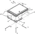
Fig. 7 is a perspective view of a container handling vehicle 201 illustrating how side surfaces 7, 8, 9, 10 may be formed on a container handling vehicle 201 of this type. In this embodiment, it should be noted that the side surfaces 7, 8, 9, 10 do not generally correspond to the housing of the container handling vehicle 201, except for the second side surface 8. Due to the cantilevered configuration of this container handling vehicle 201, the outermost portion of the cantilever 202 defines the third side surface 9 as it extends above the grid cell 122 and prevents other container handling vehicles from occupying the cell 122. Thus, the fourth side surface 10 also extends from the edge of the cantilever 202 to the second side surface 8. The three sensors 17 of the proximity sensor system 4 are illustrated as each disposed in an upper corner of the second and third side surfaces 8, 9 of the enclosure of the container handling vehicle 201, while the fourth sensor 17 is disposed near an edge of the boom 202. As will be apparent, a similar sensor 17 can be found on the side surfaces 7 and 9, which are not fully shown in fig. 7, wherein the sensor 17 is also arranged in the outermost edge of the cantilever 202 facing the first positive direction X +. Advantageously, the sensor 17 is arranged in the vicinity of the boundary of the lateral surface 7, 8, 9, 10, since this allows it to detect the presence of another container handling vehicle moving parallel to said lateral surface 7, 8, 9, 10.
In an alternative embodiment of the invention, the proximity sensor is placed on the topmost surface of the container handling vehicle. In this embodiment, a single proximity sensor may be used. The proximity sensor may be tilted or rotated so as to cover the entire 360 ° area around the container handling vehicle.
In yet another embodiment of the present invention, four proximity sensors may be placed on the topmost surface of the container handling vehicle. With four sensors, it is possible to cover the entire 360 ° area around the container handling vehicle without having to move the sensors. Each sensor covers a side of the container handling vehicle. The first proximity sensor is directed outwardly in a first positive direction and is capable of detecting another container handling vehicle within the predetermined distance from the first side surface, the second proximity sensor is directed outwardly in a first negative direction and is capable of detecting another container handling vehicle within the predetermined distance from the second side surface, the third proximity sensor is directed outwardly in a second positive direction and is capable of detecting another container handling vehicle within the predetermined distance from the third side surface, and the fourth proximity sensor is directed outwardly in a second negative direction and is capable of detecting another container handling vehicle within the predetermined distance from the fourth side surface.
Fig. 8 illustrates another type of container handling vehicle 301 having a contact area against the rail system 108 with a horizontal extension equal to the lateral area defined by the grid columns 112 or grid cells 122. As shown in fig. 8a, container handling vehicle 301 further includes an overhanging section 302 that extends laterally beyond the contact area of container handling vehicle 301 and extends into an adjacent grid cell 122 when container handling vehicle 301 is positioned over grid cell 122. The container handling vehicle 301 has a vehicle body 301a, a driving device 301b for driving in the first direction X, and a driving device 301c for driving in the second direction Y. Although the driving means 301c in the second direction Y is not shown in the side view of fig. 8a, it is visible in fig. 8b and is arranged similarly to the driving means 301b in the first direction X.
However, the overhanging section 302 does not prevent another container handling vehicle 301 from traveling over an adjacent grid cell 122, i.e., the grid cell 122 into which the overhanging section 302 of the first vehicle extends. To accomplish this, the container handling vehicles 301 each include a recessed section 303 disposed opposite the protruding section 302, the recessed section 303 being capable of receiving the protruding section 302 of the other vehicle 301 as the other vehicle passes by the adjacent grid cell 122. The recessed section 303 may have a shape that is complementary to the shape of the protruding section 302 and may extend across the entire width or length of the container handling vehicle 301, allowing the vehicles 301 to pass over each other adjacent grid cells 122. As the vehicles 301 operate on the track system 108, the recessed section 303 of each container handling vehicle 301 is able to accommodate the protruding sections 302 of the other container handling vehicles 301 as they pass adjacent grid cells 122, thereby allowing the container handling vehicles 301 to travel along adjacent rows of grid cells, as shown in fig. 8 b.
The container handling vehicle 301 in fig. 8a and 8b is included herein to show that the protruding section 301 does not necessarily prevent access to adjacent grid cells 122, but rather depends on the shape of the container handling vehicle. Thus, it will be apparent to those skilled in the art that other variations of container handling vehicles having projections or even no corresponding recesses may be employed on the track system 108 without the projections preventing other container handling vehicles from accessing adjacent grid cells 122. Thus, the difference between the container handling vehicle of fig. 7 and 8 is noteworthy in that both include portions extending above adjacent grid cells 122, however, as opposed to the container handling vehicle 301 of fig. 8, however, the only difference is that the container handling vehicle 201 of fig. 7 has a side surface 9 defined from the edge of the boom 202, where the first side surface 7 is not defined by the outermost edge of the overhang section 302.
Fig. 9 illustrates another aspect of a container handling vehicle according to the present invention, wherein a container handling vehicle 601 for container transfer is shown in fig. 9a and is associated with the automated storage and retrieval system 1 of fig. 9 b.
As shown in fig. 9a, the container transfer vehicle 601 is arranged to retrieve the storage containers 106 up and down, thus comprising a container carrier 602 arranged above the vehicle body 601a to receive the storage containers 106. The container handling vehicle 601 comprises drive means 301b in the first direction X and drive means 301c in the second direction Y, similar to the drive means of the other previously described container handling vehicles 101, 201, 301. As for the container transport vehicle 601, like the other container handling vehicles, side surfaces 7, 8, 9, 10 are defined, wherein the second side surface 8 and the fourth side surface 10 are visible in fig. 9 a. A possible proximity sensor location is also shown by reference numeral 17.
Fig. 9b shows a container transfer vehicle 601 operating on a rail system 108' below the rail system 108 of the storage grid 104. The conveyor track system 50 may be constructed in the same manner or in a similar manner as the track system 108 for the container handling vehicles 200, 300.
According to the embodiment of fig. 2b, a container handling vehicle 201 is shown operating on the rail system 108 of the storage grid 104. However, as will be apparent to those skilled in the art, any type of container handling vehicle 101, 201, 301 may operate on the rail system 108 of the grid, for example according to the embodiments shown in fig. 6-8. The container handling vehicle 201 may thus lower the storage containers down to the container transfer vehicle 601 operating on the lower track system 108'. The container transfer vehicle 601 is generally arranged to transfer the storage containers 106 to an access point (not shown) at the periphery of the track system 108 where the storage containers 106 may be picked up. Although not shown here, the lower track system 108 'typically includes a plurality of container transfer vehicles 601, and problems of jamming and queuing may occur as they move between the units below the port rows and the access points on the periphery of the lower track system 108'. Thus, the present invention is advantageously applied to a track system 108' having container transfer vehicles 601 in a similar manner to the container handling vehicles 101, 201, 301 of the track system 108 of the grid 104.
Fig. 10 shows the projection 6 on the rail system, the side surfaces 7, 8, 9, 10 and a rectangular cross section 11 formed by several different examples of container handling vehicles. The rectangular cross-section 11 labeled a may be taken from the container handling vehicle 101 of fig. 2a, 6 or 9, for example, because the rectangular cross-section 11 formed by its side surfaces is equal to the lateral area defined by the grid cells 122. The rectangular cross-section 11 labeled B is equal to the area defined by one (in the X direction) by one and one-half (in the Y direction) of the grid cells 122 and may, for example, come from a container handling vehicle having some similarity to the container handling vehicle shown in fig. 2a, but wherein one side wall of the vehicle is enlarged and occupies the area of one-half of the grid cells 122. The rectangular cross-section 11 labeled C has an irregular projection and may be a container handling vehicle 400 similar to that of the illustrative example of fig. 5. The rectangular cross section 11 labeled D may be from the container handling vehicle 201 of fig. 2b or fig. 7, for example. However, it is envisaged that a container handling vehicle similar to the container handling vehicle of fig. 2a having a lateral area corresponding to two grid cells 122 and being capable of lifting two storage containers 106 simultaneously from adjacent grid cells 122 may also form a rectangular cross-section 11 as marked D. Based on the disclosure of the present invention herein, it will be apparent to those skilled in the art that many more variations of container handling vehicles are contemplated.
Fig. 11 is a flow chart schematically illustrating the steps of a method for operating the automated storage and retrieval system 1. The method generally begins at step 700, wherein the central control unit 15 detects a conflict above the grid cell 122 caused by two container handling vehicles 2, 3. The container handling vehicle on the route to the target unit 12 is labeled as the first container handling vehicle 2 and the container handling vehicle that prevents the first container handling vehicle 2 from approaching the target unit 12 is labeled as the second container handling vehicle 3. The target unit may generally be a grid cell 122 on the track system 108, 108' where the container handling vehicle has received commands from the central control unit 15 to move. In the next step, the first container handling vehicle 2 moves to the grid cell 122 adjacent its target cell 12 and receives a data signal from the central control unit 15, which it processes in its vehicle control unit 14. The data signal includes a command to activate the proximity sensor system 4 of the first container handling device 2 to begin monitoring another container handling vehicle in the direction of the target unit 12 consistent with its direction of travel. The data signal may also include specifications for a predetermined distance D within which the first container handling vehicle 2 will detect the second container handling vehicle 3 and move into the target unit 12 once the second container handling vehicle 3 exceeds the distance D. Another data signal is transmitted from the central control unit 15 to the vehicle control unit 14 of the second container handling vehicle 3 to command the second container handling vehicle 3 to move away from the target unit 12. In some aspects, the second container handling vehicle 3 may have received a command to move away from the target unit 12 before the first container handling vehicle 2 receives a command to activate its proximity sensor system 4 and move, but the second container handling vehicle 3 has not moved, for example because it is busy lowering or lifting the storage container 106. Thus, the data signal from the central control unit to the first container handling vehicle 2 is shown by step 710 and its activation of the proximity sensor system 4 is shown by step 720. In any event, the second container handling vehicle 3 moves out of its blocking position with the target unit 12, as shown at step 730. The vehicle control unit 14 of the first container handling vehicle 2 continuously monitors data from its proximity sensor system 4 and, upon a predetermined distance D from the object (i.e., the second container handling vehicle 3), the vehicle control unit 14 controls the first container handling vehicle 2 to move into the target unit 12, as shown at step 740. Depending on the direction of travel of the second container handling vehicle 3 relative to the first container handling vehicle 3, the vehicle control unit 14 may continue to monitor whether the second container handling vehicle 3 is within a predetermined distance during movement of the first container handling vehicle 2.
In the following, with reference to fig. 12 to 15, the various steps of the method of operating an automation system according to the invention are illustrated. To illustrate this, a schematic track system and two container handling vehicles 2, 3 of one type are used throughout fig. 12-15. The container handling vehicles 2, 3 illustrated in fig. 12 to 15 have a rectangular cross section 11 equal to one by one half grid row (i.e. 1 × 1.5), as described in relation to part B of fig. 10, and comprise a container receiving space 13 arranged to one side of the vehicle body. The container handling vehicles 2, 3 may also include a proximity sensor system 4 such as shown in fig. 6-9, but only the active sensor 17, i.e., the sensor that monitors whether the second container handling vehicle 3 is within the predetermined distance D, is shown in fig. 12-15. However, the remaining sensors 17 may also be activated during the execution of the method.
Fig. 12 is a schematic top view of the track system 108 illustrating the steps of a method wherein when the method is initiated, the first container handling vehicle 2 and the second container handling vehicle 3 are positioned on adjacent grid cells 122, as shown in part a, and a data signal is transmitted to each container handling vehicle 2, 3 by the central control unit 15. The second container vehicle 3 is shown covering the entire target unit 12 and is oriented such that its container receiving space 13 is also located above the target unit 12. Such starting points as shown in fig. 12 may be common around the ports through which the target unit 12 is located above the port columns 19, 20 through which the storage containers 106 are unloaded and picked up. The first container handling vehicle 2 therefore activates its proximity sensor system 4, as indicated by the black dot 17, and continuously monitors the predetermined distance D as it moves into the target unit 12 to avoid collision with the second container handling vehicle 3.
In part B of fig. 12, the second container handling vehicle 3 moves, as indicated by the arrow, and the vehicle 3 is positioned across two grid cells 122. The proximity sensor system 4 of the first container handling vehicle 2 monitors the presence of the second container handling vehicle 3 within a predetermined distance D, which may typically be set to 2 meters when the container handling vehicles 2, 3 are moving in parallel.
Thus, part C of fig. 12 shows the first container handling vehicle 2 after detecting that the second container handling vehicle 3 is not present within the predetermined distance D, and both container handling vehicles 2, 3 are moving across the track system 108. Thus, the proximity sensor system 4 of the first container handling vehicle 2 may be continuously monitored in the first positive direction X + to avoid a collision, for example, if the second container handling vehicle 3 is accidentally stopped. It should be noted that when the first container handling vehicle 2 begins to move, the second container handling vehicle 3 is partially located within the target unit 12.
Part D of fig. 12 shows the end result of the method, wherein the first container handling vehicle 2 has moved over the target unit 12 and the second container handling vehicle 3 has moved to a new position on the track system 108. In general, the new location of the second container handling vehicle 3 may be associated with a new task such as retrieving or depositing the storage container 106 somewhere in the grid 104.
Fig. 13 is a schematic top view of the track system 108 showing the steps of a method wherein a first container handling vehicle 2 is positioned on a grid cell 122 adjacent its unoccupied target cell 12 while a second container handling vehicle 3 prevents access to the target cell 12 due to the size of the first container handling vehicle 2 and hence the rectangular cross section 11. The steps shown in section a-B of fig. 13 are substantially the same as those of fig. 12, however, only the sensor 17 in the corner of the first container handling vehicle 2 closest to the second container handling vehicle 3 need be activated. The central control unit 14 may transmit the direction of travel and position of the second container handling vehicle 3 whereupon the vehicle control unit 14 of the first container handling vehicle 2 may determine which sensors are required to monitor the presence of the second container handling vehicle 3 within a predetermined distance. Alternatively, the central control unit 15 may issue direct commands to the first container handling vehicle 2 as to which sensors are to be activated.
Fig. 14 is a schematic top view of the track system 108 showing the steps of a method in which a first container handling vehicle 2 is positioned on a grid cell 122 adjacent its target cell 12 that is partially occupied by a second container handling vehicle 3 due to the different orientation of the two vehicles 2, 3 on the track system 108. The steps shown in section a-B in fig. 13 are substantially the same as those in fig. 14.
Fig. 15 is a schematic top view of the track system 108 illustrating the steps of a method wherein the first container handling vehicle 2 and the second container handling vehicle 3 are initially positioned on adjacent grid cells 122 similar to the starting point of the method in fig. 12. However, contrary to the steps of fig. 12, the second container handling vehicle 3 moves in a direction orthogonal to the direction in which the first container handling vehicle 2 travels, as shown in part B of fig. 15. Thus, the sensor 17 of the first container handling vehicle 2 arranged in the corner of the direction of travel of the second container handling vehicle 3 is activated. Furthermore, the predetermined distance D at which the proximity sensor system 4 detects the second container handling vehicle 3 may be less than 2 (two) meters, for example 10 (ten) centimeters, as it is only necessary to detect when the second container handling vehicle 3 has passed a corner thereof. The vehicle control unit 14 of the first container handling vehicle 2 may receive information from the central control unit 15 regarding the predetermined distance D and which sensor to activate, or the vehicle control unit 14 may determine the distance and which sensor to activate by receiving information regarding the direction of travel of the second container handling vehicle 3. Once the sensor 17 of the first container handling vehicle 2 detects the absence of an obstacle, the container handling vehicle 2 may move into the target unit 12. In a prior art implementation of the method shown in fig. 15, the central control unit 15 may not know that the target unit 12 is idle until the second container handling vehicle 3 has moved at least to the position shown in part D of fig. 15, thus causing the first container handling device 3 to wait too long for movement into the target unit 12. The steps of the method in fig. 15 thus clearly illustrate the time saving aspects of the invention.
The predetermined distance D may be dynamically adapted to the speed at which the container handling vehicle is moving. The container handling vehicle is set to have a default predetermined distance D for a given speed. The container handling vehicle itself will adapt the distance D to the speed at which it is travelling.
In the foregoing description, various aspects of automated storage and retrieval systems and methods of operating automated storage and retrieval systems according to the present invention have been described with reference to illustrative embodiments. However, this description is not intended to be construed in a limiting sense. Various modifications and changes of the illustrative embodiments, as well as other embodiments of the system and method, which are apparent to persons skilled in the art, are deemed to fall within the scope of the invention as defined by the appended claims.
Reference numbers: