CN112261907A - Noise reduction shielding technology in surface electromyogram signal measurement and related system and method - Google Patents
Noise reduction shielding technology in surface electromyogram signal measurement and related system and method Download PDFInfo
- Publication number
- CN112261907A CN112261907A CN201980035465.1A CN201980035465A CN112261907A CN 112261907 A CN112261907 A CN 112261907A CN 201980035465 A CN201980035465 A CN 201980035465A CN 112261907 A CN112261907 A CN 112261907A
- Authority
- CN
- China
- Prior art keywords
- wearable device
- semg
- electromagnetic shield
- electrodes
- wearer
- Prior art date
- Legal status (The legal status is an assumption and is not a legal conclusion. Google has not performed a legal analysis and makes no representation as to the accuracy of the status listed.)
- Pending
Links
Images


Classifications
-
- A—HUMAN NECESSITIES
- A61—MEDICAL OR VETERINARY SCIENCE; HYGIENE
- A61B—DIAGNOSIS; SURGERY; IDENTIFICATION
- A61B5/00—Measuring for diagnostic purposes; Identification of persons
- A61B5/68—Arrangements of detecting, measuring or recording means, e.g. sensors, in relation to patient
- A61B5/6801—Arrangements of detecting, measuring or recording means, e.g. sensors, in relation to patient specially adapted to be attached to or worn on the body surface
- A61B5/6813—Specially adapted to be attached to a specific body part
- A61B5/6824—Arm or wrist
-
- A—HUMAN NECESSITIES
- A61—MEDICAL OR VETERINARY SCIENCE; HYGIENE
- A61B—DIAGNOSIS; SURGERY; IDENTIFICATION
- A61B5/00—Measuring for diagnostic purposes; Identification of persons
- A61B5/68—Arrangements of detecting, measuring or recording means, e.g. sensors, in relation to patient
- A61B5/6801—Arrangements of detecting, measuring or recording means, e.g. sensors, in relation to patient specially adapted to be attached to or worn on the body surface
- A61B5/6802—Sensor mounted on worn items
- A61B5/681—Wristwatch-type devices
-
- A—HUMAN NECESSITIES
- A61—MEDICAL OR VETERINARY SCIENCE; HYGIENE
- A61B—DIAGNOSIS; SURGERY; IDENTIFICATION
- A61B5/00—Measuring for diagnostic purposes; Identification of persons
- A61B5/24—Detecting, measuring or recording bioelectric or biomagnetic signals of the body or parts thereof
- A61B5/25—Bioelectric electrodes therefor
- A61B5/279—Bioelectric electrodes therefor specially adapted for particular uses
- A61B5/296—Bioelectric electrodes therefor specially adapted for particular uses for electromyography [EMG]
-
- H—ELECTRICITY
- H03—ELECTRONIC CIRCUITRY
- H03F—AMPLIFIERS
- H03F1/00—Details of amplifiers with only discharge tubes, only semiconductor devices or only unspecified devices as amplifying elements
- H03F1/26—Modifications of amplifiers to reduce influence of noise generated by amplifying elements
-
- H—ELECTRICITY
- H05—ELECTRIC TECHNIQUES NOT OTHERWISE PROVIDED FOR
- H05K—PRINTED CIRCUITS; CASINGS OR CONSTRUCTIONAL DETAILS OF ELECTRIC APPARATUS; MANUFACTURE OF ASSEMBLAGES OF ELECTRICAL COMPONENTS
- H05K9/00—Screening of apparatus or components against electric or magnetic fields
- H05K9/0007—Casings
-
- A—HUMAN NECESSITIES
- A61—MEDICAL OR VETERINARY SCIENCE; HYGIENE
- A61B—DIAGNOSIS; SURGERY; IDENTIFICATION
- A61B2562/00—Details of sensors; Constructional details of sensor housings or probes; Accessories for sensors
- A61B2562/04—Arrangements of multiple sensors of the same type
- A61B2562/043—Arrangements of multiple sensors of the same type in a linear array
-
- A—HUMAN NECESSITIES
- A61—MEDICAL OR VETERINARY SCIENCE; HYGIENE
- A61B—DIAGNOSIS; SURGERY; IDENTIFICATION
- A61B2562/00—Details of sensors; Constructional details of sensor housings or probes; Accessories for sensors
- A61B2562/18—Shielding or protection of sensors from environmental influences, e.g. protection from mechanical damage
- A61B2562/182—Electrical shielding, e.g. using a Faraday cage
-
- A—HUMAN NECESSITIES
- A61—MEDICAL OR VETERINARY SCIENCE; HYGIENE
- A61B—DIAGNOSIS; SURGERY; IDENTIFICATION
- A61B5/00—Measuring for diagnostic purposes; Identification of persons
- A61B5/24—Detecting, measuring or recording bioelectric or biomagnetic signals of the body or parts thereof
- A61B5/30—Input circuits therefor
- A61B5/307—Input circuits therefor specially adapted for particular uses
- A61B5/313—Input circuits therefor specially adapted for particular uses for electromyography [EMG]
-
- H—ELECTRICITY
- H03—ELECTRONIC CIRCUITRY
- H03F—AMPLIFIERS
- H03F2200/00—Indexing scheme relating to amplifiers
- H03F2200/261—Amplifier which being suitable for instrumentation applications
-
- H—ELECTRICITY
- H03—ELECTRONIC CIRCUITRY
- H03F—AMPLIFIERS
- H03F2203/00—Indexing scheme relating to amplifiers with only discharge tubes or only semiconductor devices as amplifying elements covered by H03F3/00
- H03F2203/45—Indexing scheme relating to differential amplifiers
- H03F2203/45544—Indexing scheme relating to differential amplifiers the IC comprising one or more capacitors, e.g. coupling capacitors
-
- H—ELECTRICITY
- H03—ELECTRONIC CIRCUITRY
- H03F—AMPLIFIERS
- H03F2203/00—Indexing scheme relating to amplifiers with only discharge tubes or only semiconductor devices as amplifying elements covered by H03F3/00
- H03F2203/45—Indexing scheme relating to differential amplifiers
- H03F2203/45548—Indexing scheme relating to differential amplifiers the IC comprising one or more capacitors as shunts to earth or as short circuit between inputs
-
- H—ELECTRICITY
- H03—ELECTRONIC CIRCUITRY
- H03F—AMPLIFIERS
- H03F2203/00—Indexing scheme relating to amplifiers with only discharge tubes or only semiconductor devices as amplifying elements covered by H03F3/00
- H03F2203/45—Indexing scheme relating to differential amplifiers
- H03F2203/45604—Indexing scheme relating to differential amplifiers the IC comprising a input shunting resistor
-
- H—ELECTRICITY
- H03—ELECTRONIC CIRCUITRY
- H03F—AMPLIFIERS
- H03F3/00—Amplifiers with only discharge tubes or only semiconductor devices as amplifying elements
- H03F3/45—Differential amplifiers
- H03F3/45071—Differential amplifiers with semiconductor devices only
- H03F3/45076—Differential amplifiers with semiconductor devices only characterised by the way of implementation of the active amplifying circuit in the differential amplifier
- H03F3/45475—Differential amplifiers with semiconductor devices only characterised by the way of implementation of the active amplifying circuit in the differential amplifier using IC blocks as the active amplifying circuit
Landscapes
- Health & Medical Sciences (AREA)
- Life Sciences & Earth Sciences (AREA)
- Engineering & Computer Science (AREA)
- Heart & Thoracic Surgery (AREA)
- Molecular Biology (AREA)
- Biophysics (AREA)
- Pathology (AREA)
- Biomedical Technology (AREA)
- Veterinary Medicine (AREA)
- Medical Informatics (AREA)
- Physics & Mathematics (AREA)
- Surgery (AREA)
- Animal Behavior & Ethology (AREA)
- General Health & Medical Sciences (AREA)
- Public Health (AREA)
- Power Engineering (AREA)
- Microelectronics & Electronic Packaging (AREA)
- Measurement And Recording Of Electrical Phenomena And Electrical Characteristics Of The Living Body (AREA)
Abstract
Techniques for shielding a wearable surface electromyography (sEMG) device are described. According to some aspects, a sEMG device may include an amplification circuit including at least a first differential amplifier and at least two sEMG electrodes electrically connected to the amplification circuit. The apparatus may further include: at least one auxiliary conductor not electrically connected to the amplification circuit, wherein the at least one auxiliary conductor is configured to electrically couple to a wearer of the wearable device; and an electromagnetic shield at least partially surrounding the wearable device and electrically connected to the at least one auxiliary conductor.
Description
Background
Surface electromyography (sEMG) is a process that involves detecting electrical activity produced by one or more groups of muscles at rest and/or during activity. High quality sEMG signals are typically obtained from wet electrodes in a laboratory environment using skin preparations that require the application of a gel or paste at the electrode-skin interface to improve electrical conductivity between the skin and the electrodes. In wireless communication applications, shielding is commonly used to reduce radio frequency interference and is typically achieved by covering all or part of the circuitry with shielding material connected to a ground plane (ground plane).
SUMMARY
According to some aspects, there is provided a wearable device comprising: an amplification circuit comprising at least a first differential amplifier; at least two sEMG electrodes electrically connected to an amplification circuit; at least one auxiliary conductor not electrically connected to the amplification circuit, wherein the at least one auxiliary conductor is configured to electrically couple to a wearer of the wearable device; and an electromagnetic shield at least partially surrounding the wearable device and electrically connected to the at least one auxiliary conductor.
According to some aspects, a method of attenuating noise in a wearable device is provided, the wearable device including an amplification circuit, at least two sEMG electrodes electrically connected to an input of the amplification circuit, and an electromagnetic shield at least partially surrounding the wearable device, the method including electrically coupling the at least two sEMG electrodes to a wearer of the wearable device, and electrically coupling the electromagnetic shield to the wearer without electrically coupling the electromagnetic shield to the amplification circuit other than via the wearer and via air between the electromagnetic shield and the amplification circuit.
It should be appreciated that all combinations of the foregoing concepts and additional concepts discussed in greater detail below (assuming such concepts are not mutually inconsistent) are contemplated as being part of the inventive subject matter disclosed herein. In particular, all combinations of claimed subject matter appearing at the end of this disclosure are contemplated as being part of the inventive subject matter disclosed herein.
Brief Description of Drawings
Various non-limiting embodiments of the technology will be described with reference to the following drawings. It should be appreciated that the drawings are not necessarily drawn to scale.
Fig. 1 is a schematic diagram of components of a sEMG system according to some embodiments of the technology described herein;
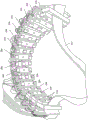
fig. 2 illustrates a wristband having sEMG sensors circumferentially disposed thereon according to some embodiments of the technology described herein;
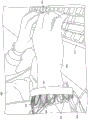
FIG. 3 illustrates a user wearing the wristband of FIG. 2 while typing on a keyboard in accordance with some embodiments of the technology described herein;
fig. 4 depicts an illustrative amplifier of a sEMG device according to some embodiments;
fig. 5 depicts an illustrative amplifier of a sEMG device according to some embodiments, wherein a shield mitigates interference generated by an external noise source; and
fig. 6A-6D depict illustrative cross-sectional views of a sEMG device including a shield surrounding electronics of the sEMG device, according to some embodiments.
Detailed Description
Obtaining consistent high quality sEMG signals using sEMG electrodes and conventional signal conditioning and processing techniques is challenging, in part due to the low voltage generated by the muscle fibers. Furthermore, obtaining high quality sEMG signals from dry sEMG electrodes is generally more challenging than with wet sEMG electrodes, since wet sEMG electrodes typically have a lower impedance conduction path between the electrode and the skin through the intervening gel. However, with dry sEMG electrodes, various low conductivity materials may be present between the electrodes and the skin, such as air, body hair, and/or moisture, resulting in inconsistent electrode signals that may exhibit considerable noise. For applications requiring near real-time analysis of sEMG signals using dry electrodes, it is important to obtain consistent high quality signals using reliable equipment, both from a user experience perspective and a development perspective. As referred to herein, sEMG signals are signals generated by one or more sEMG electrodes, and are typically generated by electrodes in response to electrical signals generated by one or more muscles or muscle groups.
The inventors have recognized and appreciated that sEMG signals are inherently low amplitude (e.g., in the range of a few μ V to a few mV), and are particularly susceptible to external noise sources that may capacitively couple through the air to the circuit containing the sEMG electrodes. For example, external noise may be coupled through the air to the input of the sEMG data acquisition system, especially in the case of high impedance inputs. External noise sources may include, for example, AC power cords and AC powered devices, which may generate sources of 50Hz or 60Hz noise. Although the capacitance of air is relatively small (e.g., on the order of femto farads), the voltage of the sEMG signal may be low enough that even severely attenuated external noise sources may produce signals that interfere with accurate measurement of the sEMG signal.
The inventors have further recognized and appreciated that conventional methods of shielding circuits function poorly in sEMG devices (i.e., devices that include one or more sEMG electrodes). For example, conventional shielding techniques typically place conductors around the circuit and connect the conductors directly to circuit ground or some other well-defined potential. However, the inventors have observed that this approach does not significantly suppress the signal generated within the sEMG device by external noise sources, and may even increase the amount of noise in the sEMG signal in some cases.
Some embodiments are directed to techniques for suppressing signals generated within a sEMG device by an external noise source by electrically coupling a shielding structure to the skin of a wearer of a wearable device, the wearable device including a sEMG sensor disposed thereon. The shielding structure acts to substantially suppress signals generated in the sEMG device by external noise sources. Such noise suppression may occur even if the wearer's body provides a ground that is not typically well-defined and not necessarily at a stable potential.
Fig. 1 schematically depicts components of an illustrative sEMG system 100, according to some embodiments. The system 100 includes a pair of sEMG electrodes 110, which may include any combination of wet sEMG electrodes and/or dry sEMG electrodes. In some embodiments, the electrodes 110 may be arranged as part of a wearable device configured to be worn on or around a portion of a user's body. For example, in one non-limiting example, a plurality of sEMG sensors including sEMG electrodes (e.g., electrodes 110) are circumferentially arranged around an adjustable and/or elastic band, such as a wrist band or arm band configured to be worn around a wrist or arm of a user. Alternatively, at least some sEMG sensors may be arranged on a wearable patch configured to be secured to a portion of a user's body.
In some embodiments, the sEMG electrodes may be minimally invasive and may include one or more electrically conductive elements placed in or through all or part of the user's dermis. In at least some instances of the above arrangements, the resulting EMG signal may not be considered a "surface" EMG signal in a strict technical sense. Nevertheless, reducing external noise sources is also a fundamental challenge for minimally invasive EMG recording.
In one implementation, 16 sEMG sensors including sEMG electrodes are circumferentially arranged around an elastic band configured to be worn around a lower arm of a user. For example, fig. 2 shows sEMG sensors 204 arranged circumferentially around elastic band 202. It should be appreciated that any suitable number of sEMG sensors with any suitable number of sEMG electrodes (including wet sEMG electrodes and/or dry sEMG electrodes) may be used, and the number and arrangement of sensors/electrodes may depend on the particular application for which the wearable device is used. For example, as shown in fig. 2, some sEMG sensors 204 include two sEMG electrodes, while other sEMG sensors 204 include three sEMG electrodes, with the middle of the three electrodes being a ground electrode. A ground electrode may be included on one or more sEMG sensors 204 to, for example, further bias skin potential and/or filter out noise. Although the schematic diagrams in fig. 1, 4 and 5 only show two or three electrodes connected to the amplifier, it should be appreciated that for a sEMG sensor 204 in which three (or more) electrodes are used, a corresponding number of connections between the electrodes and the amplification circuitry would be included. In one example application of the techniques described herein, fig. 3 shows a user 306 wearing an elastic band 302 on a hand 308. In this manner, the sEMG sensor 304 may be configured to record sEMG signals as the user controls the keypad 312 using the fingers 310.
The surface potential recorded by sEMG electrodes is usually small and amplification of the signal recorded by sEMG electrodes is usually required. As shown in fig. 1, sEMG electrodes 110 are coupled to an amplification circuit 112 configured to amplify sEMG signals recorded by the electrodes. The output of the amplification circuit 112 is provided to an analog-to-digital converter (ADC) circuit 114, and the analog-to-digital converter circuit 114 converts the amplified sEMG signal into a digital signal for further processing by a microprocessor 116. The microprocessor 116 may be implemented by one or more hardware processors. The processed signals output from the microprocessor 116 may be interpreted by a host computer 120, examples of which include, but are not limited to, a desktop computer, a laptop computer, a smart watch, a smart phone, or any other computing device. In some implementations, the host 120 may be configured to output one or more control signals for controlling a physical or virtual device based at least in part on an analysis of the signals output from the microprocessor 116.
As shown, the sEMG system 100 also includes a sensor 118, and the sensor 118 can be configured to record a type of information about the state of the user in addition to the sEMG information. For example, the sensors 118 may include, but are not limited to, temperature sensors configured to measure skin/electrode temperature, Inertial Measurement Unit (IMU) sensors configured to measure motion information such as rotation and acceleration, humidity sensors, heart rate monitoring sensors, and other biochemical sensors configured to provide information about the user and/or the user's environment.
One illustrative implementation of the amplification circuit 112 shown in fig. 1 is shown in fig. 4, according to some embodiments. In the example of sEMG device 400 shown in fig. 4, sEMG electrodes 441, 442 and 443 (which are examples of electrodes 110 shown in fig. 1, and may include any combination of wet sEMG electrodes and/or dry sEMG electrodes) are electrically coupled to the body 450 of the user. Due to the nature of the contact provided by the sEMG electrodes, the coupling between each of the electrodes 441, 442, 443 and the body 450, respectively, is with the resistance Rin+、Rin0、Rin-Are associated with and each have a capacitance Cin+、Cin0、Cin-And (4) associating. The values of these resistances and capacitances may be expected to vary between electrodes due to, for example, one or more of the following: variations in skin conditions (e.g., hydration level, number of intervening body hairs), different amounts of physical contact between the respective electrodes and the skin, and/or manufacturing variations between electrodes 441, 442, and 443.
In the example of FIG. 4, the signals sensed by electrodes 441 and 443 are provided to the input of differential amplifier 420, differential amplifier 420 being powered using dual power supplies, voltage + V with respect to ground (424)CC(423) As a positive power supply and a voltage-VCC(426) As a negative power supply. The amplified signal generated by amplifier 420 is output at 425. Electrode 442 is connected to circuit ground 424. In at least some cases, the connection of electrode 442 to circuit ground 424 can function to bias body 450; for example, the connection may stabilize the bulk DC potential at circuit ground.
As described above, in some cases, an external noise source may be coupled to the sEMG device through the air. For example, in the example of fig. 4, noise source 410 may be coupled through air to the inputs of the amplifier circuit, represented in fig. 4 by capacitors 431 and 432, which capacitors 431 and 432 represent the parasitic capacitance between noise source 410 and the input of amplifier 420. And thus may produce unwanted noise in output 425.
For example, based on the illustrated parasitic capacitances of air and amplifier inputs from electrodes 441 and 443 shown in FIG. 4 andignoring resistor R for simplicityin+、Rin0、Rin-The voltage signal generated by the noise source 410 as an input to the amplifier 420 can be expressed as:
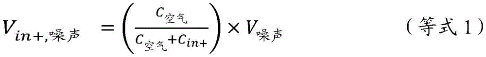
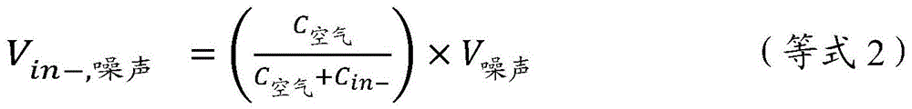
wherein VNoise(s)Is a noise signal generated by noise source 410 (e.g., a 60Hz signal generated by an AC power cable and/or an AC powered device). Note that in addition to the sEMG voltage signal sensed from the body 450 by the electrodes 441 and 443, the voltage V isin +, noiseAnd Vin-noiseWhich is also the voltage signal input to amplifier 420. Furthermore, it should be appreciated that in some cases, the capacitance of air may not be the same in each of the equations above, but is treated as such for simplicity, due to slight differences in the distance between the noise source and the amplifier.
As shown in equations 1 and 2, the noise signal VNoise(s)Is attenuated by air, but because of Cin+And Cin-Generally not equal, Vin +, noiseAnd Vin-noiseAnd are not equal. As a result, a differential noise input is generated at the input of the amplifier 420. Furthermore, although the capacitance of air may be on the order of femto farads, the capacitance Cin+And Cin-And can typically be on the order of nanofarads. As a result, the attenuation factor in equations 1 and 2 may be about 10-6. For many devices, such a level of attenuation of the noise signal (e.g., resulting in a noise signal on the order of 1 μ V) results in noise at a level much lower than the signal within the device. However, for sEMG electrode devices, the voltage recorded by the electrodes is also typically small (on the order of μ V or less), so that even attenuated noise signals are problematic and interfere with the sEMG signal input to the amplifier 420. In addition, the reason is thatFor sEMG devices often used in environments containing multiple electronic devices (e.g., AC mains equipment, computer processors, displays, etc.), multiple sources of such noise may exacerbate this problem.
Fig. 5 depicts an illustrative amplifier 520 of a sEMG device 500 according to some embodiments, wherein a shield 560 is arranged to mitigate interference caused by external noise. Shield 560 may be referred to as an "electromagnetic shield" because it mitigates electromagnetic interference, although it may be appreciated that in at least some instances, the shield may not interact with both the electric and magnetic fields when shielding external sources of interference.
As with the example of FIG. 4, in the apparatus 500, an external noise source 510 generates a noise signal V at the input of an amplifier 520in +, noiseAnd Vin-noise. To reduce the effect of this noise, a shield 560 is disposed between the noise source 510 and the amplifier 520 and is coupled to the user's body 550. Shield 560 generates noise signal VNoise(s)As described in more detail below. The shield 560 can include any suitable conductive material or materials including, but not limited to, one or more metals and/or alloys (e.g., aluminum, copper, and/or mu metal), conductive coatings (e.g., silver and/or carbon-based coatings), conductive fabrics (e.g., silver nanowires), conductive polymers (e.g., carbon or graphene filled polylactic acid (PLA)), conductive plastics, conductive rubbers, conductive silicones, or combinations thereof. The shield 560 can also include one or more non-conductive components that can be combined with any one or more conductive components, such as the foregoing examples.
Air-based illustrated parasitic capacitance (C)Air (a)And C'Air (a)) Amplifier inputs from the electrodes 541 and 543 shown in fig. 5 and a capacitance C representing the coupling of the shield 560 to the user's body 550BodyThe voltage signal generated by the noise source 510 as an input to the amplifier 520 may be expressed as:

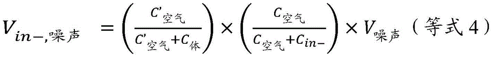
wherein the resistance RBody、Rin+、Rin0、Rin-Again omitted for simplicity.
CBodyCan be expected to be on the order of nanofarads, and thus exist in equations 3 and 4 as compared to the single attenuation factor in equations 1 and 2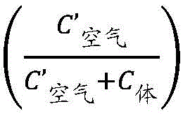 Using the circuit configuration shown in the example of fig. 5 results in greater attenuation of noise at the input of
 amplifier 520.
It will be appreciated that the parasitic capacitances of air 531 and 532 may be different from each other in all cases due to slight differences in the environment between the noise source and the shield, but are handled as such in the discussion above for simplicity. Similarly, it will be appreciated that the parasitic capacitances of air 533 and 534 may be different from each other in all cases due to slight differences in the environment between the shield and the amplifier, but are handled as such in the discussion above for simplicity.
It will be appreciated that the shield 560 may be disposed between the noise source 510 and the amplifier 520 in a variety of ways, and that the shield 560 may have any suitable geometry to achieve such an arrangement. In some embodiments, shield 560 encloses (e.g., completely surrounds) the amplifier such that the shield is disposed between the amplifier and an external noise source. In some embodiments, shield 560 may surround the amplifier such that the shield is disposed between the amplifier and a noise source, which may be incident on the amplifier from some directions, but in some directions the shield does not completely enclose the amplifier. It will also be appreciated that the shield 560 can completely surround or partially surround the entire sEMG system, such as the sEMG system 100 shown in fig. 1.
For example, in the case of the illustrative sEMG devices shown in fig. 2 and 3, the shield 560 can be implemented as a conductive layer surrounding the sEMG sensors 204 and/or 304 without the shield being located between the sEMG sensors 204 and/or 304 and the skin of the wearer. Such an arrangement may achieve attenuation of noise by coupling the shield to the wearer's body in any of a variety of ways, examples of which will be discussed below.
Furthermore, although the shield 560 is coupled to the wearer's body through the sEMG electrodes 545 in the example of fig. 5, the shield may generally be electrically coupled to the wearer's body in any suitable manner using any number of auxiliary conductors (i.e., conductors other than the sEMG electrodes connected to one or more amplifier inputs of the device). For example, the shield may be electrically coupled to the wearer's body by one or more electrodes other than sEMG electrodes and/or by one or more other conductors. In some implementations, the auxiliary conductor may be part of the shield itself.
The shield 560 can be electrically coupled to any suitable portion or portions of the wearer's body. For example, in the case of a sEMG device configured to be worn on an arm, the shield may be configured to be electrically coupled to the same arm, including the ventral and/or dorsal side of the arm and/or other parts of the body (e.g., the other arm). The presence of body hair on the surface of the body is a complicating factor for achieving good electrical contact with the body for surface mounted electrodes. Electrically coupling the shield to the ventral side of the arm may be advantageous, since the ventral side of the arm typically has less body hair than the dorsal side, resulting in a better coupling of the shield to the body. It should be appreciated that the desired or optimal placement of the electrodes/conductors connected to the shield 560 on the body of the user may vary from user to user depending on one or more factors including, but not limited to, the density of the body hair, the type of wearable sEMG device, and user preferences.
Although the techniques discussed above with respect to fig. 1, 2, 3, 4, and 5 are discussed in the context of differential input amplifiers, it will be appreciated that the masking techniques described herein may also be implemented with other types of amplifiers, such as single-ended input amplifiers, instead of the differential input amplifiers in the above examples. As may be noted from equations 3 and 4 above, the amplitude of the noise may be attenuated at each individual input of the amplifier, which may also be the case for amplifiers other than differential input amplifiers.
Fig. 6A-6C depict illustrative cross-sectional views of a sEMG device including a shield that completely or partially surrounds the electronics (e.g., one or more amplifiers or even the entire sEMG system) of the sEMG device, according to some embodiments. In the example of fig. 6A, sEMG device 600 includes a shield 603 surrounding device electronics 602 and sEMG electrodes 604. The shield 603 extends onto the wearer's body 601 to electrically couple the shield to the body, as discussed above with respect to fig. 5. As a result, shield 603 attenuates external noise sources (not shown) that may be coupled to aspects (aspect) of device electronics 602.
According to some embodiments, the shield 603 may comprise and/or may form a portion of a housing of the sEMG device 600. As a non-limiting example, the shield 603 may include a rigid conductor that forms a housing around the device electronics 602 and contacts the body 601; the shield 603 may include a conductive material disposed on the exterior, interior, and/or embedded within a housing surrounding the device electronics 602 such that the conductive material contacts the body 601 (e.g., a conductive paint applied to the housing); and/or shield 603 may comprise a conductive fabric that may or may not be attached to the housing around device electronics 602.
In the example of fig. 6B, sEMG device 620 includes a shield 623 surrounding device electronics 622 and sEMG electrodes 624, and further includes an electrically conductive ring 625 (shown in cross-section) connected to the shield, the electrically conductive ring 625 electrically coupling the shield to the body, as discussed above with respect to fig. 5. As a result, shield 623 attenuates sources of external noise (not depicted) that may be coupled to various aspects of device electronics 622. In some embodiments, the conductive loop may be a metal loop that extends partially or completely around the wearer's body 621.
According to some embodiments, the shield 623 may include and/or may form a portion of a housing of the sEMG device 620. As a non-limiting example, the shield 623 may include a rigid conductor forming a housing around the device electronics 622 and contacting the body 621; the shield 623 can include a conductive material disposed on the exterior, interior, and/or embedded within a housing surrounding the device electronics 622 such that the conductive material contacts the body 621 (e.g., a conductive paint applied to the housing); and/or shield 623 may comprise a conductive fabric that may or may not be attached to a housing around device electronics 622.
In the example of fig. 6C, the sEMG device 640 includes a shield 643 surrounding device electronics 642 and sEMG electrodes 644, and further includes an electrode 646 connected to the shield, the electrode 646 electrically coupling the shield to the body, as discussed above with respect to fig. 5. As a result, the shield 643 attenuates sources of external noise (not depicted) that may be coupled to various aspects of the device electronics 642. In some embodiments, the electrodes 646 can be sEMG electrodes.
According to some embodiments, the shield 643 may include and/or may form a portion of a housing of the sEMG device 640. As a non-limiting example, the shield 643 may include a rigid conductor that forms a housing around the device electronics 642 and contacts the body 641; the shield 643 can include electrically conductive material that is disposed on the exterior, interior, and/or embedded within a housing that surrounds the device electronics 642 such that the electrically conductive material contacts the body 641 (e.g., electrically conductive paint applied to the housing); and/or the shield 643 may include conductive fabric that may or may not be attached to a housing around the device electronics 642.
In the example of fig. 6D, the components 662a and circuit board 662b of the device electronics are shown as separate elements, with conductive traces 662c of the circuit board 662b also shown. The illustrative sEMG device 660 includes a shield 663 that covers a device circuit board 662b and conductive traces 662c routed on the circuit board 662 b. The device 660 further comprises sEMG electrodes 664 and electrodes 666 connected to the shield, which electrodes 666 electrically couple the shield to the body as discussed above with respect to fig. 5. As a result, shield 663 attenuates external noise sources (not depicted) that may couple to conductive trace 662 c. In some embodiments, electrodes 666 may be sEMG electrodes. As a non-limiting example, the shield 663 may be implemented as a shielding film layer laminated onto the circuit board 662 b. In the example of fig. 6D, the shield is thus disposed around a portion of the device electronics (i.e., device circuit board 662b), but not necessarily around component 662a of the device electronics, in order for the shield to attenuate external noise sources.
Having thus described several aspects of at least one embodiment of this invention, it is to be appreciated various alterations, modifications, and improvements will readily occur to those skilled in the art.
Such alterations, modifications, and improvements are intended to be part of this disclosure, and are intended to be within the spirit and scope of the invention. Moreover, while advantages of the invention are pointed out, it should be appreciated that not every embodiment of the technology described herein will include every described advantage. Some embodiments may not implement any features as described herein as advantageous, and in some instances one or more of the described features may be implemented to implement additional embodiments. Accordingly, the foregoing description and drawings are by way of example only.
As used herein, elements referred to as being electrically coupled to each other are arranged such that a change in electrical potential in one element can cause a change in electrical potential in another element. In this manner, the noise source 510 in the example of fig. 5 is electrically coupled to the amplifier 520 and the shield 560. Further, as used herein, elements that are said to be electrically connected to each other are arranged such that electrical conductors directly connect the elements together. For example, the electrode 545 in the example of fig. 5 may be electrically connected to a shield 560.
Implementations of the DC-coupled amplification circuits described herein employ discrete analog circuit components. It should be appreciated, however, that all or portions of the amplification circuitry and/or associated circuitry in the signal chain may alternatively be implemented using AC-coupled amplification circuitry, one or more Application Specific Integrated Circuits (ASICs), and/or any commercial or custom silicon implementation, as the embodiments are not limited in this respect. Furthermore, it will be appreciated that in some embodiments, the amplification circuitry may not be included in the sEMG device, but rather an analog-to-digital converter (ADC) may directly acquire the sEMG signal.
While the examples discussed above are discussed in the context of an interface with an EMG sensor, it should be understood that the shielding techniques for noise reduction described herein may also be implemented in wearable interfaces with other types of sensors, including but not limited to Electrocardiogram (ECG), electroencephalogram (EEG), mechanical electromyogram (MMG) sensors, phonocardiogram (SMG) sensors, and Electrical Impedance Tomography (EIT) sensors.
Various aspects of the devices and techniques described herein may be used alone, in combination, or in a variety of arrangements not specifically discussed in the embodiments described in the foregoing description, and are therefore not limited in their application to the details and arrangement of components set forth in the foregoing description or illustrated in the drawings. For example, aspects described in one embodiment may be combined in any manner with aspects described in other embodiments.
Use of ordinal terms such as "first," "second," "third," etc., in the claims to modify a claim element does not by itself connote any priority, precedence, or order of one claim element over another or the temporal order in which acts of a method are performed, but are used merely as labels to distinguish one claim element having a certain name from another element having a same name (but for use of the ordinal term) to distinguish the claim elements.
Also, the phraseology and terminology used herein is for the purpose of description and should not be regarded as limiting. The use of "including," "comprising," or "having," "containing," "involving," and variations thereof herein, is meant to encompass the items listed thereafter and equivalents thereof as well as additional items.
Claims (24)
Applications Claiming Priority (5)
| Application Number | Priority Date | Filing Date | Title |
|---|---|---|---|
| US201862677574P | 2018-05-29 | 2018-05-29 | |
| US62/677,574 | 2018-05-29 | ||
| US201862696242P | 2018-07-10 | 2018-07-10 | |
| US62/696,242 | 2018-07-10 | ||
| PCT/US2019/034173 WO2019231911A1 (en) | 2018-05-29 | 2019-05-28 | Shielding techniques for noise reduction in surface electromyography signal measurement and related systems and methods |
Publications (1)
| Publication Number | Publication Date |
|---|---|
| CN112261907A true CN112261907A (en) | 2021-01-22 |
Family
ID=68694889
Family Applications (1)
| Application Number | Title | Priority Date | Filing Date |
|---|---|---|---|
| CN201980035465.1A Pending CN112261907A (en) | 2018-05-29 | 2019-05-28 | Noise reduction shielding technology in surface electromyogram signal measurement and related system and method |
Country Status (4)
| Country | Link |
|---|---|
| US (2) | US10687759B2 (en) |
| EP (1) | EP3801216A4 (en) |
| CN (1) | CN112261907A (en) |
| WO (1) | WO2019231911A1 (en) |
Cited By (1)
| Publication number | Priority date | Publication date | Assignee | Title |
|---|---|---|---|---|
| CN115736858A (en) * | 2022-11-22 | 2023-03-07 | 深圳市量子慧智科技有限公司 | Vital sign monitoring circuit and vital sign monitoring equipment |
Families Citing this family (20)
| Publication number | Priority date | Publication date | Assignee | Title |
|---|---|---|---|---|
| US12504816B2 (en) | 2013-08-16 | 2025-12-23 | Meta Platforms Technologies, Llc | Wearable devices and associated band structures for sensing neuromuscular signals using sensor pairs in respective pods with communicative pathways to a common processor |
| US11921471B2 (en) | 2013-08-16 | 2024-03-05 | Meta Platforms Technologies, Llc | Systems, articles, and methods for wearable devices having secondary power sources in links of a band for providing secondary power in addition to a primary power source |
| US20150124566A1 (en) | 2013-10-04 | 2015-05-07 | Thalmic Labs Inc. | Systems, articles and methods for wearable electronic devices employing contact sensors |
| WO2015081113A1 (en) | 2013-11-27 | 2015-06-04 | Cezar Morun | Systems, articles, and methods for electromyography sensors |
| WO2020112986A1 (en) | 2018-11-27 | 2020-06-04 | Facebook Technologies, Inc. | Methods and apparatus for autocalibration of a wearable electrode sensor system |
| CN112040858B (en) | 2017-10-19 | 2024-06-07 | 元平台技术有限公司 | Systems and methods for identifying biological structures associated with neuromuscular source signals |
| US11961494B1 (en) | 2019-03-29 | 2024-04-16 | Meta Platforms Technologies, Llc | Electromagnetic interference reduction in extended reality environments |
| US11481030B2 (en) | 2019-03-29 | 2022-10-25 | Meta Platforms Technologies, Llc | Methods and apparatus for gesture detection and classification |
| US11493993B2 (en) | 2019-09-04 | 2022-11-08 | Meta Platforms Technologies, Llc | Systems, methods, and interfaces for performing inputs based on neuromuscular control |
| US11150730B1 (en) | 2019-04-30 | 2021-10-19 | Facebook Technologies, Llc | Devices, systems, and methods for controlling computing devices via neuromuscular signals of users |
| US11907423B2 (en) | 2019-11-25 | 2024-02-20 | Meta Platforms Technologies, Llc | Systems and methods for contextualized interactions with an environment |
| CN112261907A (en) | 2018-05-29 | 2021-01-22 | 脸谱科技有限责任公司 | Noise reduction shielding technology in surface electromyogram signal measurement and related system and method |
| WO2020061451A1 (en) | 2018-09-20 | 2020-03-26 | Ctrl-Labs Corporation | Neuromuscular text entry, writing and drawing in augmented reality systems |
| WO2021071915A1 (en) | 2019-10-08 | 2021-04-15 | Unlimited Tomorrow, Inc. | Biometric sensor array |
| NO20200093A1 (en) * | 2020-01-24 | 2021-07-26 | ||
| SE544237C2 (en) * | 2020-03-16 | 2022-03-08 | Piotrode Medical Ab | Shielded body electrode for recording electrophysiological signals from a body providing a contact between the shield and the skin of the body |
| US11868531B1 (en) | 2021-04-08 | 2024-01-09 | Meta Platforms Technologies, Llc | Wearable device providing for thumb-to-finger-based input gestures detected based on neuromuscular signals, and systems and methods of use thereof |
| WO2023164211A1 (en) * | 2022-02-25 | 2023-08-31 | Meta Platforms Technologies, Llc | Smart electrodes for sensing signals and processing signals using internally-housed signal-processing components at wearable devices and wearable devices incorporating the smart electrodes |
| US12411549B2 (en) * | 2022-11-02 | 2025-09-09 | Meta Platforms Technologies, Llc | Wearable band structure having a band portion including embedded structural members with signal-processing components and another band portion not including any electrical components, and systems, devices, and methods of manufacturing thereof |
| CN115444426B (en) * | 2022-11-09 | 2023-04-28 | 之江实验室 | On-chip electrode integrated wireless myoelectricity SoC system, chip and acquisition device |
Citations (4)
| Publication number | Priority date | Publication date | Assignee | Title |
|---|---|---|---|---|
| US3735425A (en) * | 1971-02-10 | 1973-05-29 | Us Of America The Secretary Of | Myoelectrically controlled prothesis |
| US20150045689A1 (en) * | 2011-11-08 | 2015-02-12 | Bitron S.P.A. | Device for measuing electromyographic signals with high resolution and high number channels |
| US20150141784A1 (en) * | 2013-11-12 | 2015-05-21 | Thalmic Labs Inc. | Systems, articles, and methods for capacitive electromyography sensors |
| US20150223716A1 (en) * | 2013-05-15 | 2015-08-13 | Polar Electro Oy | Heart activity sensor structure |
Family Cites Families (247)
| Publication number | Priority date | Publication date | Assignee | Title |
|---|---|---|---|---|
| US4055168A (en) * | 1976-09-21 | 1977-10-25 | The Rockefeller University | Posture training device |
| IL78244A0 (en) | 1986-03-24 | 1986-07-31 | Zvi Kamil | Instrumentation amplifier arrangement |
| US5625577A (en) | 1990-12-25 | 1997-04-29 | Shukyohojin, Kongo Zen Sohonzan Shorinji | Computer-implemented motion analysis method using dynamics |
| JP3103427B2 (en) | 1992-04-01 | 2000-10-30 | ダイヤメディカルシステム株式会社 | Bioelectricity detector |
| WO1995027341A1 (en) * | 1994-04-04 | 1995-10-12 | Motorola Inc. | Shielded circuit assembly and method for forming same |
| AU3954997A (en) | 1996-08-14 | 1998-03-06 | Nurakhmed Nurislamovich Latypov | Method for following and imaging a subject's three-dimensional position and orientation, method for presenting a virtual space to a subject, and systems for implementing said methods |
| US6009210A (en) | 1997-03-05 | 1999-12-28 | Digital Equipment Corporation | Hands-free interface to a virtual reality environment using head tracking |
| WO2000010455A1 (en) | 1998-08-24 | 2000-03-02 | Emory University | Method and apparatus for predicting the onset of seizures based on features derived from signals indicative of brain activity |
| US6745062B1 (en) | 1998-10-05 | 2004-06-01 | Advanced Imaging Systems, Inc. | Emg electrode apparatus and positioning system |
| US6244873B1 (en) | 1998-10-16 | 2001-06-12 | At&T Corp. | Wireless myoelectric control apparatus and methods |
| US6774885B1 (en) | 1999-01-20 | 2004-08-10 | Motek B.V. | System for dynamic registration, evaluation, and correction of functional human behavior |
| US6411843B1 (en) | 1999-05-28 | 2002-06-25 | Respironics, Inc. | Method and apparatus for producing a model EMG signal from a measured EMG signal |
| US6720984B1 (en) | 2000-06-13 | 2004-04-13 | The United States Of America As Represented By The Administrator Of The National Aeronautics And Space Administration | Characterization of bioelectric potentials |
| US20030184544A1 (en) | 2000-07-24 | 2003-10-02 | Prudent Jean Nicholson | Modeling human beings by symbol manipulation |
| WO2002037827A2 (en) | 2000-10-30 | 2002-05-10 | Naval Postgraduate School | Method and apparatus for motion tracking of an articulated rigid body |
| US20030144829A1 (en) | 2002-01-25 | 2003-07-31 | Geatz Michael W. | System and method for sensing and evaluating physiological parameters and modeling an adaptable predictive analysis for symptoms management |
| JP2003255993A (en) | 2002-03-04 | 2003-09-10 | Ntt Docomo Inc | Speech recognition system, speech recognition method, speech recognition program, speech synthesis system, speech synthesis method, speech synthesis program |
| US6942621B2 (en) | 2002-07-11 | 2005-09-13 | Ge Medical Systems Information Technologies, Inc. | Method and apparatus for detecting weak physiological signals |
| EP1537823A1 (en) | 2002-09-11 | 2005-06-08 | National Institute of Information and Communications Technology Incorporated Administrative Agency | Active muscle display device |
| KR100506084B1 (en) | 2002-10-24 | 2005-08-05 | 삼성전자주식회사 | Apparatus and method for searching acupuncture point |
| ATE413902T1 (en) | 2003-08-18 | 2008-11-15 | Cardiac Pacemakers Inc | PATIENT MONITORING SYSTEM |
| JP4178186B2 (en) | 2003-08-21 | 2008-11-12 | 国立大学法人 筑波大学 | Wearable motion assist device, control method for wearable motion assist device, and control program |
| CN1838933B (en) | 2003-08-21 | 2010-12-08 | 国立大学法人筑波大学 | Wearable motion assistance device, method for controlling wearable motion assistance device, and control program |
| US7565295B1 (en) | 2003-08-28 | 2009-07-21 | The George Washington University | Method and apparatus for translating hand gestures |
| US7574253B2 (en) | 2003-09-26 | 2009-08-11 | Northwestern University | Signal processing using non-linear regression with a sinusoidal model |
| US7961909B2 (en) | 2006-03-08 | 2011-06-14 | Electronic Scripting Products, Inc. | Computer interface employing a manipulated object with absolute pose detection component and a display |
| EP1782733B1 (en) | 2004-06-16 | 2019-03-13 | The University of Tokyo | Muscular strength acquiring method and device based on musculoskeletal model |
| US20060206167A1 (en) | 2005-01-06 | 2006-09-14 | Flaherty J C | Multi-device patient ambulation system |
| WO2006105094A2 (en) | 2005-03-29 | 2006-10-05 | Duke University | Sensor system for identifying and tracking movements of multiple sources |
| US7428516B2 (en) | 2005-06-23 | 2008-09-23 | Microsoft Corporation | Handwriting recognition using neural networks |
| US8190249B1 (en) | 2005-08-01 | 2012-05-29 | Infinite Biomedical Technologies, Llc | Multi-parametric quantitative analysis of bioelectrical signals |
| US7725147B2 (en) | 2005-09-29 | 2010-05-25 | Nellcor Puritan Bennett Llc | System and method for removing artifacts from waveforms |
| US8280503B2 (en) | 2008-10-27 | 2012-10-02 | Michael Linderman | EMG measured during controlled hand movement for biometric analysis, medical diagnosis and related analysis |
| JP4826459B2 (en) | 2006-01-12 | 2011-11-30 | 株式会社豊田中央研究所 | Musculoskeletal model creation method, human stress / strain estimation method, program, and recording medium |
| US8762733B2 (en) | 2006-01-30 | 2014-06-24 | Adidas Ag | System and method for identity confirmation using physiologic biometrics to determine a physiologic fingerprint |
| US7580742B2 (en) | 2006-02-07 | 2009-08-25 | Microsoft Corporation | Using electroencephalograph signals for task classification and activity recognition |
| US7827000B2 (en) | 2006-03-03 | 2010-11-02 | Garmin Switzerland Gmbh | Method and apparatus for estimating a motion parameter |
| US8311623B2 (en) | 2006-04-15 | 2012-11-13 | The Board Of Trustees Of The Leland Stanford Junior University | Systems and methods for estimating surface electromyography |
| EP2010053A4 (en) | 2006-04-21 | 2010-05-12 | Quantum Applied Science And Re | System for measuring electric signals |
| GB2453263A (en) | 2006-05-16 | 2009-04-01 | Douglas S Greer | System and method for modeling the neocortex and uses therefor |
| US7661068B2 (en) | 2006-06-12 | 2010-02-09 | Microsoft Corporation | Extended eraser functions |
| US9405372B2 (en) | 2006-07-14 | 2016-08-02 | Ailive, Inc. | Self-contained inertial navigation system for interactive control using movable controllers |
| US7848797B2 (en) | 2006-08-17 | 2010-12-07 | Neurometrix, Inc. | Motor unit number estimation (MUNE) for the assessment of neuromuscular function |
| US8437844B2 (en) | 2006-08-21 | 2013-05-07 | Holland Bloorview Kids Rehabilitation Hospital | Method, system and apparatus for real-time classification of muscle signals from self-selected intentional movements |
| JP4267648B2 (en) | 2006-08-25 | 2009-05-27 | 株式会社東芝 | Interface device and method thereof |
| US7885732B2 (en) | 2006-10-25 | 2011-02-08 | The Boeing Company | Systems and methods for haptics-enabled teleoperation of vehicles and other devices |
| US20080221487A1 (en) | 2007-03-07 | 2008-09-11 | Motek Bv | Method for real time interactive visualization of muscle forces and joint torques in the human body |
| JP5357142B2 (en) | 2007-04-24 | 2013-12-04 | コーニンクレッカ フィリップス エヌ ヴェ | Sensor arrangement and method for measuring physiological parameters |
| FR2916069B1 (en) | 2007-05-11 | 2009-07-31 | Commissariat Energie Atomique | PROCESSING METHOD FOR MOTION CAPTURE OF ARTICULATED STRUCTURE |
| DE102007044555A1 (en) | 2007-07-18 | 2009-01-22 | Siemens Ag | Optical coupling device and method for its production |
| US8726194B2 (en) | 2007-07-27 | 2014-05-13 | Qualcomm Incorporated | Item selection using enhanced control |
| JP5559691B2 (en) | 2007-09-24 | 2014-07-23 | クアルコム,インコーポレイテッド | Enhanced interface for voice and video communication |
| US20090082692A1 (en) | 2007-09-25 | 2009-03-26 | Hale Kelly S | System And Method For The Real-Time Evaluation Of Time-Locked Physiological Measures |
| US7714757B2 (en) | 2007-09-26 | 2010-05-11 | Medtronic, Inc. | Chopper-stabilized analog-to-digital converter |
| US8343079B2 (en) | 2007-10-18 | 2013-01-01 | Innovative Surgical Solutions, Llc | Neural monitoring sensor |
| FI20075798A0 (en) * | 2007-11-12 | 2007-11-12 | Polar Electro Oy | The electrode structure |
| GB0800144D0 (en) | 2008-01-04 | 2008-02-13 | Fitzpatrick Adam P | Electrocardiographic device and method |
| US9597015B2 (en) | 2008-02-12 | 2017-03-21 | Portland State University | Joint angle tracking with inertial sensors |
| US20100030532A1 (en) | 2008-06-12 | 2010-02-04 | Jasbir Arora | System and methods for digital human model prediction and simulation |
| US8447704B2 (en) | 2008-06-26 | 2013-05-21 | Microsoft Corporation | Recognizing gestures from forearm EMG signals |
| US8170656B2 (en) | 2008-06-26 | 2012-05-01 | Microsoft Corporation | Wearable electromyography-based controllers for human-computer interface |
| US9037530B2 (en) | 2008-06-26 | 2015-05-19 | Microsoft Technology Licensing, Llc | Wearable electromyography-based human-computer interface |
| US8444564B2 (en) | 2009-02-02 | 2013-05-21 | Jointvue, Llc | Noninvasive diagnostic system |
| EP2427109A4 (en) | 2009-05-07 | 2015-01-07 | Massachusetts Eye & Ear Infirm | PROCESSING SIGNALS IN PHYSIOLOGICAL NOISE |
| US8376968B2 (en) | 2009-05-15 | 2013-02-19 | The Hong Kong Polytechnic University | Method and system for quantifying an intention of movement of a user |
| US20100315266A1 (en) | 2009-06-15 | 2010-12-16 | Microsoft Corporation | Predictive interfaces with usability constraints |
| WO2011012988A1 (en) | 2009-07-30 | 2011-02-03 | University Of Cape Town | Non-invasive deep muscle electromyography |
| US8718980B2 (en) | 2009-09-11 | 2014-05-06 | Qualcomm Incorporated | Method and apparatus for artifacts mitigation with multiple wireless sensors |
| US20110077484A1 (en) | 2009-09-30 | 2011-03-31 | Nellcor Puritan Bennett Ireland | Systems And Methods For Identifying Non-Corrupted Signal Segments For Use In Determining Physiological Parameters |
| TWI496558B (en) | 2009-10-20 | 2015-08-21 | Tatung Co | System and method for measuring electrocardiogram and respiratory signal using two-pole electrode patch |
| US8421634B2 (en) | 2009-12-04 | 2013-04-16 | Microsoft Corporation | Sensing mechanical energy to appropriate the body for data input |
| EP2512331A4 (en) | 2009-12-16 | 2015-01-14 | Ictalcare As | EPILEPSY CRISIS PREDICTION SYSTEM |
| US9268404B2 (en) | 2010-01-08 | 2016-02-23 | Microsoft Technology Licensing, Llc | Application gesture interpretation |
| US8631355B2 (en) | 2010-01-08 | 2014-01-14 | Microsoft Corporation | Assigning gesture dictionaries |
| JP5471490B2 (en) | 2010-01-20 | 2014-04-16 | オムロンヘルスケア株式会社 | Body motion detection device |
| EP2548153A1 (en) | 2010-03-16 | 2013-01-23 | Carlo Trugenberger | Authentication system, method for authenticating an object, apparatus for producing an identication device, method for producing an identification device |
| US8351651B2 (en) | 2010-04-26 | 2013-01-08 | Microsoft Corporation | Hand-location post-process refinement in a tracking system |
| US8588884B2 (en) * | 2010-05-28 | 2013-11-19 | Emkinetics, Inc. | Microneedle electrode |
| US8754862B2 (en) | 2010-07-11 | 2014-06-17 | Lester F. Ludwig | Sequential classification recognition of gesture primitives and window-based parameter smoothing for high dimensional touchpad (HDTP) user interfaces |
| FR2962821B1 (en) | 2010-07-13 | 2013-02-22 | Commissariat Energie Atomique | METHOD AND SYSTEM FOR CLASSIFYING NEURAL SIGNALS, AND METHOD FOR SELECTING ELECTRODES FOR DIRECT NEURONAL CONTROL. |
| EP2600813B1 (en) | 2010-08-02 | 2021-01-20 | The Johns Hopkins University | Surgical system using cooperativ manual/robot-control and audio feedback |
| US20120066163A1 (en) | 2010-09-13 | 2012-03-15 | Nottingham Trent University | Time to event data analysis method and system |
| US20130123656A1 (en) | 2010-11-15 | 2013-05-16 | Sandy L. Heck | Control System and Apparatus Utilizing Signals Originating in the Periauricular Neuromuscular System |
| WO2012155157A1 (en) | 2011-05-06 | 2012-11-15 | Azoteq (Pty) Ltd | Multiple media capacitive sensor |
| US9251588B2 (en) | 2011-06-20 | 2016-02-02 | Nokia Technologies Oy | Methods, apparatuses and computer program products for performing accurate pose estimation of objects |
| US9128521B2 (en) | 2011-07-13 | 2015-09-08 | Lumo Bodytech, Inc. | System and method of biomechanical posture detection and feedback including sensor normalization |
| US9707393B2 (en) | 2011-08-26 | 2017-07-18 | National Yunlin University Of Science And Technology | Feedback-control wearable upper-limb electrical stimulation device |
| KR20220032059A (en) | 2011-09-19 | 2022-03-15 | 아이사이트 모빌 테크놀로지 엘티디 | Touch free interface for augmented reality systems |
| US20130077820A1 (en) | 2011-09-26 | 2013-03-28 | Microsoft Corporation | Machine learning gesture detection |
| FR2981561B1 (en) | 2011-10-21 | 2015-03-20 | Commissariat Energie Atomique | METHOD FOR DETECTING MOTION SENSOR ACTIVITY, CORRESPONDING DEVICE AND COMPUTER PROGRAM |
| WO2013071285A1 (en) | 2011-11-11 | 2013-05-16 | Rutgers, The State University Of New Jersey | Methods for the diagnosis and treatment of neurological disorders |
| US10430066B2 (en) | 2011-12-06 | 2019-10-01 | Nri R&D Patent Licensing, Llc | Gesteme (gesture primitive) recognition for advanced touch user interfaces |
| JP2013206273A (en) | 2012-03-29 | 2013-10-07 | Sony Corp | Information processing apparatus, information processing method, and information processing system |
| WO2013151770A1 (en) | 2012-04-03 | 2013-10-10 | Carnegie Mellon University | Musculoskeletal activity recognition system and method |
| WO2013177592A2 (en) | 2012-05-25 | 2013-11-28 | Emotiv Lifesciences, Inc. | System and method for providing and aggregating biosignals and action data |
| US9278453B2 (en) | 2012-05-25 | 2016-03-08 | California Institute Of Technology | Biosleeve human-machine interface |
| US9891718B2 (en) | 2015-04-22 | 2018-02-13 | Medibotics Llc | Devices for measuring finger motion and recognizing hand gestures |
| US9814426B2 (en) | 2012-06-14 | 2017-11-14 | Medibotics Llc | Mobile wearable electromagnetic brain activity monitor |
| US9582072B2 (en) | 2013-09-17 | 2017-02-28 | Medibotics Llc | Motion recognition clothing [TM] with flexible electromagnetic, light, or sonic energy pathways |
| US10921886B2 (en) | 2012-06-14 | 2021-02-16 | Medibotics Llc | Circumferential array of electromyographic (EMG) sensors |
| US20150366504A1 (en) | 2014-06-20 | 2015-12-24 | Medibotics Llc | Electromyographic Clothing |
| US8484022B1 (en) | 2012-07-27 | 2013-07-09 | Google Inc. | Adaptive auto-encoders |
| US20150182165A1 (en) | 2012-08-03 | 2015-07-02 | Neurotopia, Inc. | Neurophysiological training headset |
| US10234941B2 (en) | 2012-10-04 | 2019-03-19 | Microsoft Technology Licensing, Llc | Wearable sensor for tracking articulated body-parts |
| US10413251B2 (en) * | 2012-10-07 | 2019-09-17 | Rhythm Diagnostic Systems, Inc. | Wearable cardiac monitor |
| US9351653B1 (en) | 2012-11-29 | 2016-05-31 | Intan Technologies, LLC | Multi-channel reconfigurable systems and methods for sensing biopotential signals |
| WO2014085910A1 (en) | 2012-12-04 | 2014-06-12 | Interaxon Inc. | System and method for enhancing content using brain-state data |
| US20140196131A1 (en) | 2013-01-07 | 2014-07-10 | Salutron, Inc. | User authentication based on a wrist vein pattern |
| US20140198034A1 (en) | 2013-01-14 | 2014-07-17 | Thalmic Labs Inc. | Muscle interface device and method for interacting with content displayed on wearable head mounted displays |
| US9459697B2 (en) | 2013-01-15 | 2016-10-04 | Leap Motion, Inc. | Dynamic, free-space user interactions for machine control |
| WO2014130871A1 (en) | 2013-02-22 | 2014-08-28 | Thalmic Labs Inc. | Methods and devices that combine muscle activity sensor signals and inertial sensor signals for gesture-based control |
| US20140245200A1 (en) | 2013-02-25 | 2014-08-28 | Leap Motion, Inc. | Display control with gesture-selectable control paradigms |
| US20140249397A1 (en) | 2013-03-01 | 2014-09-04 | Thalmic Labs Inc. | Differential non-contact biopotential sensor |
| US9361411B2 (en) | 2013-03-15 | 2016-06-07 | Honeywell International, Inc. | System and method for selecting a respirator |
| US9766709B2 (en) | 2013-03-15 | 2017-09-19 | Leap Motion, Inc. | Dynamic user interactions for display control |
| US9436287B2 (en) | 2013-03-15 | 2016-09-06 | Qualcomm Incorporated | Systems and methods for switching processing modes using gestures |
| US20140277622A1 (en) | 2013-03-15 | 2014-09-18 | First Principles, Inc. | System and method for bio-signal control of an electronic device |
| IN2013MU01148A (en) | 2013-03-26 | 2015-04-24 | Tata Consultancy Services Ltd | |
| US10620709B2 (en) | 2013-04-05 | 2020-04-14 | Ultrahaptics IP Two Limited | Customized gesture interpretation |
| US9717440B2 (en) | 2013-05-03 | 2017-08-01 | The Florida International University Board Of Trustees | Systems and methods for decoding intended motor commands from recorded neural signals for the control of external devices or to interact in virtual environments |
| WO2014186370A1 (en) | 2013-05-13 | 2014-11-20 | Thalmic Labs Inc. | Systems, articles and methods for wearable electronic devices that accommodate different user forms |
| US10620775B2 (en) | 2013-05-17 | 2020-04-14 | Ultrahaptics IP Two Limited | Dynamic interactive objects |
| US9218574B2 (en) | 2013-05-29 | 2015-12-22 | Purepredictive, Inc. | User interface for machine learning |
| EP3777677B1 (en) | 2013-05-31 | 2024-11-06 | President And Fellows Of Harvard College | Soft exosuit for assistance with human motion |
| KR101933921B1 (en) | 2013-06-03 | 2018-12-31 | 삼성전자주식회사 | Method and apparatus for estimating pose |
| US9383819B2 (en) | 2013-06-03 | 2016-07-05 | Daqri, Llc | Manipulation of virtual object in augmented reality via intent |
| WO2014197443A1 (en) | 2013-06-03 | 2014-12-11 | Kacyvenski Isaiah | Motion sensor and analysis |
| US11083402B2 (en) | 2013-06-04 | 2021-08-10 | Medtronic, Inc. | Patient state determination based on one or more spectral characteristics of a bioelectrical brain signal |
| KR101501661B1 (en) | 2013-06-10 | 2015-03-12 | 한국과학기술연구원 | Wearable electromyogram sensor system |
| WO2014204330A1 (en) | 2013-06-17 | 2014-12-24 | 3Divi Company | Methods and systems for determining 6dof location and orientation of head-mounted display and associated user movements |
| US20140376773A1 (en) | 2013-06-21 | 2014-12-25 | Leap Motion, Inc. | Tunable operational parameters in motion-capture and touchless interface operation |
| US10402517B2 (en) | 2013-06-26 | 2019-09-03 | Dassault Systémes Simulia Corp. | Musculo-skeletal modeling using finite element analysis, process integration, and design optimization |
| US9408316B2 (en) | 2013-07-22 | 2016-08-02 | Thalmic Labs Inc. | Systems, articles and methods for strain mitigation in wearable electronic devices |
| US20150029092A1 (en) | 2013-07-23 | 2015-01-29 | Leap Motion, Inc. | Systems and methods of interpreting complex gestures |
| US20150124566A1 (en) | 2013-10-04 | 2015-05-07 | Thalmic Labs Inc. | Systems, articles and methods for wearable electronic devices employing contact sensors |
| US11426123B2 (en) | 2013-08-16 | 2022-08-30 | Meta Platforms Technologies, Llc | Systems, articles and methods for signal routing in wearable electronic devices that detect muscle activity of a user using a set of discrete and separately enclosed pod structures |
| WO2015027089A1 (en) | 2013-08-23 | 2015-02-26 | Thalmic Labs Inc. | Systems, articles, and methods for human-electronics interfaces |
| US9788789B2 (en) | 2013-08-30 | 2017-10-17 | Thalmic Labs Inc. | Systems, articles, and methods for stretchable printed circuit boards |
| US9372535B2 (en) | 2013-09-06 | 2016-06-21 | Thalmic Labs Inc. | Systems, articles, and methods for electromyography-based human-electronics interfaces |
| US9483123B2 (en) | 2013-09-23 | 2016-11-01 | Thalmic Labs Inc. | Systems, articles, and methods for gesture identification in wearable electromyography devices |
| EP3048955A2 (en) | 2013-09-25 | 2016-08-03 | MindMaze SA | Physiological parameter measurement and feedback system |
| US9389694B2 (en) | 2013-10-22 | 2016-07-12 | Thalmic Labs Inc. | Systems, articles, and methods for gesture identification in wearable electromyography devices |
| CN103777752A (en) | 2013-11-02 | 2014-05-07 | 上海威璞电子科技有限公司 | Gesture recognition device based on arm muscle current detection and motion sensor |
| GB2519987B (en) | 2013-11-04 | 2021-03-03 | Imperial College Innovations Ltd | Biomechanical activity monitoring |
| US9594433B2 (en) | 2013-11-05 | 2017-03-14 | At&T Intellectual Property I, L.P. | Gesture-based controls via bone conduction |
| EP3068349A4 (en) | 2013-11-13 | 2017-12-13 | Hrl Laboratories, Llc | System for controlling brain machine interfaces and neural prosthetic systems |
| WO2015081113A1 (en) | 2013-11-27 | 2015-06-04 | Cezar Morun | Systems, articles, and methods for electromyography sensors |
| US20150157944A1 (en) | 2013-12-06 | 2015-06-11 | Glenn I. Gottlieb | Software Application for Generating a Virtual Simulation for a Sport-Related Activity |
| US9367139B2 (en) | 2013-12-12 | 2016-06-14 | Thalmic Labs Inc. | Systems, articles, and methods for gesture identification in wearable electromyography devices |
| US9524580B2 (en) | 2014-01-06 | 2016-12-20 | Oculus Vr, Llc | Calibration of virtual reality systems |
| US9659403B1 (en) | 2014-01-06 | 2017-05-23 | Leap Motion, Inc. | Initializing orientation in space for predictive information for free space gesture control and communication |
| US9613262B2 (en) | 2014-01-15 | 2017-04-04 | Leap Motion, Inc. | Object detection and tracking for providing a virtual device experience |
| US9600030B2 (en) | 2014-02-14 | 2017-03-21 | Thalmic Labs Inc. | Systems, articles, and methods for elastic electrical cables and wearable electronic devices employing same |
| US10254843B2 (en) | 2014-02-28 | 2019-04-09 | Vikas Gupta | Gesture operated wrist mounted camera system |
| US10613642B2 (en) | 2014-03-12 | 2020-04-07 | Microsoft Technology Licensing, Llc | Gesture parameter tuning |
| US20150261306A1 (en) | 2014-03-17 | 2015-09-17 | Thalmic Labs Inc. | Systems, devices, and methods for selecting between multiple wireless connections |
| US10199008B2 (en) | 2014-03-27 | 2019-02-05 | North Inc. | Systems, devices, and methods for wearable electronic devices as state machines |
| US10409382B2 (en) | 2014-04-03 | 2019-09-10 | Honda Motor Co., Ltd. | Smart tutorial for gesture control system |
| US20150296553A1 (en) | 2014-04-11 | 2015-10-15 | Thalmic Labs Inc. | Systems, devices, and methods that establish proximity-based wireless connections |
| US9858391B2 (en) | 2014-04-17 | 2018-01-02 | The Boeing Company | Method and system for tuning a musculoskeletal model |
| US20170080346A1 (en) | 2014-05-01 | 2017-03-23 | Mohamad Abbas | Methods and systems relating to personalized evolving avatars |
| US20150325202A1 (en) | 2014-05-07 | 2015-11-12 | Thalmic Labs Inc. | Systems, devices, and methods for wearable computers with heads-up displays |
| US9785247B1 (en) | 2014-05-14 | 2017-10-10 | Leap Motion, Inc. | Systems and methods of tracking moving hands and recognizing gestural interactions |
| KR101666399B1 (en) | 2014-05-15 | 2016-10-14 | 한국과학기술연구원 | Human joint kinematics information extraction method from multi-channel surface electromyogram signals, recording medium and device for performing the method |
| USD717685S1 (en) | 2014-05-15 | 2014-11-18 | Thalmic Labs Inc. | Expandable armband |
| USD756359S1 (en) | 2014-05-15 | 2016-05-17 | Thalmic Labs Inc. | Expandable armband device |
| US9741169B1 (en) | 2014-05-20 | 2017-08-22 | Leap Motion, Inc. | Wearable augmented reality devices with object detection and tracking |
| US10782657B2 (en) | 2014-05-27 | 2020-09-22 | Ultrahaptics IP Two Limited | Systems and methods of gestural interaction in a pervasive computing environment |
| US9880632B2 (en) | 2014-06-19 | 2018-01-30 | Thalmic Labs Inc. | Systems, devices, and methods for gesture identification |
| WO2015199747A1 (en) | 2014-06-23 | 2015-12-30 | Thalmic Labs Inc. | Systems, articles, and methods for wearable human-electronics interface devices |
| US10216274B2 (en) | 2014-06-23 | 2019-02-26 | North Inc. | Systems, articles, and methods for wearable human-electronics interface devices |
| US9552069B2 (en) | 2014-07-11 | 2017-01-24 | Microsoft Technology Licensing, Llc | 3D gesture recognition |
| US9734704B2 (en) | 2014-08-12 | 2017-08-15 | Dominick S. LEE | Wireless gauntlet for electronic control |
| WO2016041088A1 (en) | 2014-09-19 | 2016-03-24 | Sulon Technologies Inc. | System and method for tracking wearable peripherals in augmented reality and virtual reality applications |
| US9811555B2 (en) | 2014-09-27 | 2017-11-07 | Intel Corporation | Recognition of free-form gestures from orientation tracking of a handheld or wearable device |
| JP6415592B2 (en) | 2014-11-12 | 2018-10-31 | 京セラ株式会社 | Wearable device |
| US9720515B2 (en) | 2015-01-02 | 2017-08-01 | Wearable Devices Ltd. | Method and apparatus for a gesture controlled interface for wearable devices |
| US9612661B2 (en) | 2015-01-02 | 2017-04-04 | Wearable Devices Ltd. | Closed loop feedback interface for wearable devices |
| US9696795B2 (en) | 2015-02-13 | 2017-07-04 | Leap Motion, Inc. | Systems and methods of creating a realistic grab experience in virtual reality/augmented reality environments |
| US20160274758A1 (en) | 2015-03-20 | 2016-09-22 | Thalmic Labs Inc. | Systems, devices, and methods for mitigating false positives in human-electronics interfaces |
| US10432842B2 (en) | 2015-04-06 | 2019-10-01 | The Texas A&M University System | Fusion of inertial and depth sensors for movement measurements and recognition |
| CN108883335A (en) | 2015-04-14 | 2018-11-23 | 约翰·詹姆斯·丹尼尔斯 | Wearable electronic multisensory interfaces for man-machine or man-man |
| US9804733B2 (en) | 2015-04-21 | 2017-10-31 | Dell Products L.P. | Dynamic cursor focus in a multi-display information handling system environment |
| US10078435B2 (en) | 2015-04-24 | 2018-09-18 | Thalmic Labs Inc. | Systems, methods, and computer program products for interacting with electronically displayed presentation materials |
| GB2537899B (en) | 2015-04-30 | 2018-02-21 | Hy5Pro As | Control of digits for artificial hand |
| US9654477B1 (en) | 2015-05-05 | 2017-05-16 | Wells Fargo Bank, N. A. | Adaptive authentication |
| US9898864B2 (en) | 2015-05-28 | 2018-02-20 | Microsoft Technology Licensing, Llc | Shared tactile interaction and user safety in shared space multi-person immersive virtual reality |
| EP3782696B1 (en) | 2015-06-02 | 2022-12-28 | Battelle Memorial Institute | Systems for neural bridging of the nervous system |
| EP3954430B1 (en) | 2015-06-02 | 2024-01-31 | Battelle Memorial Institute | Non-invasive motor impairment rehabilitation system |
| US10765859B2 (en) | 2015-06-02 | 2020-09-08 | Battelle Memorial Institute | Neural sleeve for neuromuscular stimulation, sensing and recording |
| WO2016210441A1 (en) | 2015-06-26 | 2016-12-29 | Carnegie Mellon University | System for wearable, low-cost electrical impedance tomography for non-invasive gesture recognition |
| US9240069B1 (en) | 2015-06-30 | 2016-01-19 | Ariadne's Thread (Usa), Inc. | Low-latency virtual reality display system |
| WO2017019991A1 (en) | 2015-07-29 | 2017-02-02 | Sensel Inc. | Systems and methods for manipulating a virtual environment |
| KR101626748B1 (en) | 2015-08-03 | 2016-06-14 | 숭실대학교산학협력단 | Apparatus for measuring movement pattern using brainwave and electromyogram and Method thereof |
| US10854104B2 (en) | 2015-08-28 | 2020-12-01 | Icuemotion Llc | System for movement skill analysis and skill augmentation and cueing |
| US10387034B2 (en) | 2015-09-03 | 2019-08-20 | Microsoft Technology Licensing, Llc | Modifying captured stroke information into an actionable form |
| US9824287B2 (en) | 2015-09-29 | 2017-11-21 | Huami Inc. | Method, apparatus and system for biometric identification |
| US10459537B2 (en) | 2015-09-30 | 2019-10-29 | Stmicroelectronics, Inc. | Encapsulated pressure sensor |
| US11389083B2 (en) | 2015-10-06 | 2022-07-19 | University of Pittsburgh—of the Commonwealth System of Higher Education | Method, device and system for sensing neuromuscular, physiological, biomechanical, and musculoskeletal activity |
| US9881273B2 (en) | 2015-10-28 | 2018-01-30 | Disney Interprises, Inc. | Automatic object detection and state estimation via electronic emissions sensing |
| US10595941B2 (en) | 2015-10-30 | 2020-03-24 | Orthosensor Inc. | Spine measurement system and method therefor |
| US11106273B2 (en) | 2015-10-30 | 2021-08-31 | Ostendo Technologies, Inc. | System and methods for on-body gestural interfaces and projection displays |
| US10776712B2 (en) | 2015-12-02 | 2020-09-15 | Preferred Networks, Inc. | Generative machine learning systems for drug design |
| CN105511615B (en) | 2015-12-04 | 2019-03-05 | 深圳大学 | Wearable text input system and method based on EMG |
| US20170188980A1 (en) | 2016-01-06 | 2017-07-06 | Empire Technology Development Llc | Wearable sensor based body modeling |
| WO2017120669A1 (en) | 2016-01-12 | 2017-07-20 | Bigmotion Technologies Inc. | Systems and methods for human body motion capture |
| US20170259167A1 (en) | 2016-03-14 | 2017-09-14 | Nathan Sterling Cook | Brainwave virtual reality apparatus and method |
| US9864434B2 (en) | 2016-03-30 | 2018-01-09 | Huami Inc. | Gesture control of interactive events using multiple wearable devices |
| JP6728386B2 (en) | 2016-03-31 | 2020-07-22 | センセル インコーポレイテッドSensel,Inc. | Human computer interface system |
| US10503253B2 (en) | 2016-03-31 | 2019-12-10 | Intel Corporation | Sensor signal processing to determine finger and/or hand position |
| US10852835B2 (en) | 2016-04-15 | 2020-12-01 | Board Of Regents, The University Of Texas System | Systems, apparatuses and methods for controlling prosthetic devices by gestures and other modalities |
| KR102504859B1 (en) * | 2016-04-19 | 2023-03-02 | 스카이워크스 솔루션즈, 인코포레이티드 | Optional shielding of radio frequency modules |
| US9864431B2 (en) | 2016-05-11 | 2018-01-09 | Microsoft Technology Licensing, Llc | Changing an application state using neurological data |
| US10203751B2 (en) | 2016-05-11 | 2019-02-12 | Microsoft Technology Licensing, Llc | Continuous motion controls operable using neurological data |
| US20200324104A1 (en) | 2016-05-31 | 2020-10-15 | Lab Schopfergeist Ag | Nerve stimulation apparatus and method |
| US10426371B2 (en) | 2016-06-07 | 2019-10-01 | Smk Corporation | Muscle condition measurement sheet |
| KR101790147B1 (en) | 2016-06-22 | 2017-10-25 | 재단법인 실감교류인체감응솔루션연구단 | Virtual object control system and method |
| KR20190025965A (en) | 2016-07-01 | 2019-03-12 | 엘.아이.에프.이. 코포레이션 에스.에이. | Identification of biometrics by garments having multiple sensors |
| US10772519B2 (en) | 2018-05-25 | 2020-09-15 | Facebook Technologies, Llc | Methods and apparatus for providing sub-muscular control |
| CN110300542A (en) | 2016-07-25 | 2019-10-01 | 开创拉布斯公司 | Method and apparatus for predicting musculoskeletal location information using wearable automated sensors |
| EP3487595A4 (en) | 2016-07-25 | 2019-12-25 | CTRL-Labs Corporation | SYSTEM AND METHOD FOR MEASURING MOVEMENTS OF ARTICULATED RIGID BODIES |
| CN110312471B (en) | 2016-07-25 | 2022-04-29 | 脸谱科技有限责任公司 | Adaptive system for deriving control signals from neuromuscular activity measurements |
| US10409371B2 (en) | 2016-07-25 | 2019-09-10 | Ctrl-Labs Corporation | Methods and apparatus for inferring user intent based on neuromuscular signals |
| US10765363B2 (en) | 2016-09-30 | 2020-09-08 | Cognionics, Inc. | Headgear for dry electroencephalogram sensors |
| US10162422B2 (en) | 2016-10-10 | 2018-12-25 | Deere & Company | Control of machines through detection of gestures by optical and muscle sensors |
| KR102038120B1 (en) | 2016-12-02 | 2019-10-30 | 피손 테크놀로지, 인크. | Detection and Use of Body Tissue Electrical Signals |
| US10646139B2 (en) | 2016-12-05 | 2020-05-12 | Intel Corporation | Body movement tracking |
| US20190025919A1 (en) | 2017-01-19 | 2019-01-24 | Mindmaze Holding Sa | System, method and apparatus for detecting facial expression in an augmented reality system |
| US10796599B2 (en) | 2017-04-14 | 2020-10-06 | Rehabilitation Institute Of Chicago | Prosthetic virtual reality training interface and related methods |
| US11259746B2 (en) | 2017-07-10 | 2022-03-01 | General Electric Company | Method and system for neuromuscular transmission measurement |
| US10481699B2 (en) | 2017-07-27 | 2019-11-19 | Facebook Technologies, Llc | Armband for tracking hand motion using electrical impedance measurement |
| US20190076716A1 (en) | 2017-09-12 | 2019-03-14 | Intel Corporation | Activity training system |
| CN112040858B (en) | 2017-10-19 | 2024-06-07 | 元平台技术有限公司 | Systems and methods for identifying biological structures associated with neuromuscular source signals |
| US10606620B2 (en) | 2017-11-16 | 2020-03-31 | International Business Machines Corporation | Notification interaction in a touchscreen user interface |
| US20190150777A1 (en) | 2017-11-17 | 2019-05-23 | Ctrl-Labs Corporation | Dual-supply analog circuitry for sensing surface emg signals |
| US10827942B2 (en) | 2018-01-03 | 2020-11-10 | Intel Corporation | Detecting fatigue based on electroencephalogram (EEG) data |
| WO2019147996A1 (en) | 2018-01-25 | 2019-08-01 | Ctrl-Labs Corporation | Calibration techniques for handstate representation modeling using neuromuscular signals |
| US11069148B2 (en) | 2018-01-25 | 2021-07-20 | Facebook Technologies, Llc | Visualization of reconstructed handstate information |
| WO2019147958A1 (en) | 2018-01-25 | 2019-08-01 | Ctrl-Labs Corporation | User-controlled tuning of handstate representation model parameters |
| WO2019148002A1 (en) | 2018-01-25 | 2019-08-01 | Ctrl-Labs Corporation | Techniques for anonymizing neuromuscular signal data |
| WO2019147928A1 (en) | 2018-01-25 | 2019-08-01 | Ctrl-Labs Corporation | Handstate reconstruction based on multiple inputs |
| EP3742962A4 (en) | 2018-01-25 | 2021-04-28 | Facebook Technologies, LLC. | NEUROMUSCULAR SIGNAL ARTIFACT MITIGATION METHODS AND APPARATUS |
| EP3743901A4 (en) | 2018-01-25 | 2021-03-31 | Facebook Technologies, Inc. | REAL-TIME PROCESSING OF HAND REPRESENTATION MODEL ESTIMATES |
| US20190247650A1 (en) | 2018-02-14 | 2019-08-15 | Bao Tran | Systems and methods for augmenting human muscle controls |
| US20190324549A1 (en) | 2018-04-20 | 2019-10-24 | Immersion Corporation | Systems, devices, and methods for providing immersive reality interface modes |
| EP3797345A4 (en) | 2018-05-22 | 2022-03-09 | Magic Leap, Inc. | TRANSMODAL INPUT FUSION FOR PORTABLE SYSTEM |
| CN112261907A (en) | 2018-05-29 | 2021-01-22 | 脸谱科技有限责任公司 | Noise reduction shielding technology in surface electromyogram signal measurement and related system and method |
-
2019
- 2019-05-28 CN CN201980035465.1A patent/CN112261907A/en active Pending
- 2019-05-28 WO PCT/US2019/034173 patent/WO2019231911A1/en not_active Ceased
- 2019-05-28 US US16/424,144 patent/US10687759B2/en active Active
- 2019-05-28 EP EP19810524.9A patent/EP3801216A4/en not_active Withdrawn
-
2020
- 2020-06-02 US US16/890,352 patent/US11129569B1/en active Active
Patent Citations (4)
| Publication number | Priority date | Publication date | Assignee | Title |
|---|---|---|---|---|
| US3735425A (en) * | 1971-02-10 | 1973-05-29 | Us Of America The Secretary Of | Myoelectrically controlled prothesis |
| US20150045689A1 (en) * | 2011-11-08 | 2015-02-12 | Bitron S.P.A. | Device for measuing electromyographic signals with high resolution and high number channels |
| US20150223716A1 (en) * | 2013-05-15 | 2015-08-13 | Polar Electro Oy | Heart activity sensor structure |
| US20150141784A1 (en) * | 2013-11-12 | 2015-05-21 | Thalmic Labs Inc. | Systems, articles, and methods for capacitive electromyography sensors |
Cited By (1)
| Publication number | Priority date | Publication date | Assignee | Title |
|---|---|---|---|---|
| CN115736858A (en) * | 2022-11-22 | 2023-03-07 | 深圳市量子慧智科技有限公司 | Vital sign monitoring circuit and vital sign monitoring equipment |
Also Published As
| Publication number | Publication date |
|---|---|
| US10687759B2 (en) | 2020-06-23 |
| WO2019231911A1 (en) | 2019-12-05 |
| EP3801216A1 (en) | 2021-04-14 |
| EP3801216A4 (en) | 2021-04-14 |
| US11129569B1 (en) | 2021-09-28 |
| US20190365318A1 (en) | 2019-12-05 |
Similar Documents
| Publication | Publication Date | Title |
|---|---|---|
| US11129569B1 (en) | Shielding techniques for noise reduction in surface electromyography signal measurement and related systems and methods | |
| Sullivan et al. | A low-noise, non-contact EEG/ECG sensor | |
| CN112040863A (en) | Dual power supply analog circuit for sensing surface EMG signals | |
| JP6162366B2 (en) | Biological signal measuring apparatus and method, unit measuring instrument therefor, and recording medium according to the method | |
| JP6659536B2 (en) | Potential measurement device and potential detection method | |
| US20110166434A1 (en) | System for sensing electrophysiological signals | |
| US10729379B2 (en) | Electrical wearable capacitive biosensor and noise artifact suppression method | |
| US11607126B2 (en) | Electrodes for biopotential measurement, biopotential measuring apparatus, and biopotential measuring method | |
| CN105310681B (en) | Bioelectrodes and methods and apparatus for processing biosignals using bioelectrodes | |
| US20180235499A1 (en) | Method for measuring an electrophysiological parameter by means of a capacitive electrode sensor of controlled capacitance | |
| US9588146B2 (en) | Electrode for measuring biosignal and biosignal measurement device | |
| WO2020112871A1 (en) | Contactless electrode for sensing physiological electrical activity | |
| Ding et al. | A novel front-end design for bioelectrical signal wearable acquisition | |
| Ng et al. | Impact of skin-electrode capacitance on the performance of CEMG biosensor | |
| Pratama et al. | The development of Arduino-based low-cost wireless modular device for brainwave acquisition | |
| Ping et al. | Non-contact ECG monitoring based on capacitive electrodes | |
| EP4181769B1 (en) | Apparatus for biopotential measurement | |
| Xu et al. | Design and optimization of ICs for wearable EEG sensors | |
| US12245861B1 (en) | Electrode headgear for use in electroencephalography | |
| Resende et al. | Insulated system for capacitive ECG measurement | |
| CN118576222B (en) | Wearing equipment and electrocardiogram sensor | |
| Xu et al. | Integrated Bioelectronics for Precision Health Monitoring | |
| KR20220131130A (en) | Short-range contactless active bioelectrode with active electromagnetic shielding | |
| WO2023106160A1 (en) | Biological signal detection device |
Legal Events
| Date | Code | Title | Description |
|---|---|---|---|
| PB01 | Publication | ||
| PB01 | Publication | ||
| SE01 | Entry into force of request for substantive examination | ||
| SE01 | Entry into force of request for substantive examination | ||
| CB02 | Change of applicant information | ||
| CB02 | Change of applicant information |
Address after: California, USA Applicant after: Yuan Platform Technology Co.,Ltd. Address before: California, USA Applicant before: Facebook Technologies, LLC |
|
| WD01 | Invention patent application deemed withdrawn after publication | ||
| WD01 | Invention patent application deemed withdrawn after publication |
Application publication date: 20210122 |