CN112206739B - Device for nitration of nitrogen dioxide - Google Patents
Device for nitration of nitrogen dioxide Download PDFInfo
- Publication number
- CN112206739B CN112206739B CN202011116414.2A CN202011116414A CN112206739B CN 112206739 B CN112206739 B CN 112206739B CN 202011116414 A CN202011116414 A CN 202011116414A CN 112206739 B CN112206739 B CN 112206739B
- Authority
- CN
- China
- Prior art keywords
- fixedly connected
- nitrogen dioxide
- ratchet
- cooling pipe
- groove
- Prior art date
- Legal status (The legal status is an assumption and is not a legal conclusion. Google has not performed a legal analysis and makes no representation as to the accuracy of the status listed.)
- Active
Links
- JCXJVPUVTGWSNB-UHFFFAOYSA-N nitrogen dioxide Inorganic materials O=[N]=O JCXJVPUVTGWSNB-UHFFFAOYSA-N 0.000 title claims abstract description 45
- MGWGWNFMUOTEHG-UHFFFAOYSA-N 4-(3,5-dimethylphenyl)-1,3-thiazol-2-amine Chemical compound CC1=CC(C)=CC(C=2N=C(N)SC=2)=C1 MGWGWNFMUOTEHG-UHFFFAOYSA-N 0.000 title claims abstract description 44
- 238000006396 nitration reaction Methods 0.000 title claims abstract description 10
- 238000001816 cooling Methods 0.000 claims abstract description 67
- 238000009423 ventilation Methods 0.000 claims abstract description 43
- 238000006243 chemical reaction Methods 0.000 claims abstract description 38
- 230000000694 effects Effects 0.000 claims abstract description 10
- 230000006835 compression Effects 0.000 claims description 25
- 238000007906 compression Methods 0.000 claims description 25
- QVGXLLKOCUKJST-UHFFFAOYSA-N atomic oxygen Chemical compound [O] QVGXLLKOCUKJST-UHFFFAOYSA-N 0.000 claims description 14
- 239000001301 oxygen Substances 0.000 claims description 14
- 229910052760 oxygen Inorganic materials 0.000 claims description 14
- 238000005192 partition Methods 0.000 claims description 10
- 238000002347 injection Methods 0.000 claims description 5
- 239000007924 injection Substances 0.000 claims description 5
- 230000000670 limiting effect Effects 0.000 claims description 4
- 238000001125 extrusion Methods 0.000 claims description 2
- 238000002640 oxygen therapy Methods 0.000 claims 2
- 239000012295 chemical reaction liquid Substances 0.000 abstract description 13
- MWUXSHHQAYIFBG-UHFFFAOYSA-N Nitric oxide Chemical compound O=[N] MWUXSHHQAYIFBG-UHFFFAOYSA-N 0.000 abstract description 12
- 239000007788 liquid Substances 0.000 abstract description 12
- 238000002156 mixing Methods 0.000 abstract description 4
- 230000007246 mechanism Effects 0.000 abstract description 3
- 238000009834 vaporization Methods 0.000 abstract description 2
- 230000008016 vaporization Effects 0.000 abstract description 2
- 239000007921 spray Substances 0.000 description 8
- 238000000034 method Methods 0.000 description 7
- 239000002253 acid Substances 0.000 description 6
- 238000010586 diagram Methods 0.000 description 5
- 238000004519 manufacturing process Methods 0.000 description 5
- 239000007789 gas Substances 0.000 description 4
- 239000000463 material Substances 0.000 description 4
- 230000008569 process Effects 0.000 description 4
- 230000009471 action Effects 0.000 description 3
- 239000000243 solution Substances 0.000 description 3
- 239000002699 waste material Substances 0.000 description 3
- QAOWNCQODCNURD-UHFFFAOYSA-N Sulfuric acid Chemical compound OS(O)(=O)=O QAOWNCQODCNURD-UHFFFAOYSA-N 0.000 description 2
- 238000005452 bending Methods 0.000 description 2
- 239000003795 chemical substances by application Substances 0.000 description 2
- 230000005389 magnetism Effects 0.000 description 2
- 238000012986 modification Methods 0.000 description 2
- 230000004048 modification Effects 0.000 description 2
- 230000001546 nitrifying effect Effects 0.000 description 2
- 238000005507 spraying Methods 0.000 description 2
- 238000003756 stirring Methods 0.000 description 2
- 229910002651 NO3 Inorganic materials 0.000 description 1
- GRYLNZFGIOXLOG-UHFFFAOYSA-N Nitric acid Chemical compound O[N+]([O-])=O GRYLNZFGIOXLOG-UHFFFAOYSA-N 0.000 description 1
- 150000004945 aromatic hydrocarbons Chemical class 0.000 description 1
- 230000009286 beneficial effect Effects 0.000 description 1
- 230000015572 biosynthetic process Effects 0.000 description 1
- 230000008859 change Effects 0.000 description 1
- 239000000110 cooling liquid Substances 0.000 description 1
- 230000007547 defect Effects 0.000 description 1
- 239000003814 drug Substances 0.000 description 1
- 229940079593 drug Drugs 0.000 description 1
- 239000000975 dye Substances 0.000 description 1
- 230000005611 electricity Effects 0.000 description 1
- 239000003344 environmental pollutant Substances 0.000 description 1
- 238000003912 environmental pollution Methods 0.000 description 1
- 230000017525 heat dissipation Effects 0.000 description 1
- 239000007791 liquid phase Substances 0.000 description 1
- -1 nitrate aromatic hydrocarbons Chemical class 0.000 description 1
- 229910017604 nitric acid Inorganic materials 0.000 description 1
- 150000002894 organic compounds Chemical class 0.000 description 1
- 230000000737 periodic effect Effects 0.000 description 1
- 239000000575 pesticide Substances 0.000 description 1
- 231100000719 pollutant Toxicity 0.000 description 1
- 239000000047 product Substances 0.000 description 1
- 239000005060 rubber Substances 0.000 description 1
- 238000006467 substitution reaction Methods 0.000 description 1
- 239000013589 supplement Substances 0.000 description 1
- 238000003786 synthesis reaction Methods 0.000 description 1
- 239000002351 wastewater Substances 0.000 description 1
Images


Classifications
-
- B—PERFORMING OPERATIONS; TRANSPORTING
- B01—PHYSICAL OR CHEMICAL PROCESSES OR APPARATUS IN GENERAL
- B01J—CHEMICAL OR PHYSICAL PROCESSES, e.g. CATALYSIS OR COLLOID CHEMISTRY; THEIR RELEVANT APPARATUS
- B01J19/00—Chemical, physical or physico-chemical processes in general; Their relevant apparatus
- B01J19/18—Stationary reactors having moving elements inside
- B01J19/20—Stationary reactors having moving elements inside in the form of helices, e.g. screw reactors
-
- B—PERFORMING OPERATIONS; TRANSPORTING
- B01—PHYSICAL OR CHEMICAL PROCESSES OR APPARATUS IN GENERAL
- B01J—CHEMICAL OR PHYSICAL PROCESSES, e.g. CATALYSIS OR COLLOID CHEMISTRY; THEIR RELEVANT APPARATUS
- B01J19/00—Chemical, physical or physico-chemical processes in general; Their relevant apparatus
- B01J19/0053—Details of the reactor
- B01J19/0066—Stirrers
-
- B—PERFORMING OPERATIONS; TRANSPORTING
- B01—PHYSICAL OR CHEMICAL PROCESSES OR APPARATUS IN GENERAL
- B01J—CHEMICAL OR PHYSICAL PROCESSES, e.g. CATALYSIS OR COLLOID CHEMISTRY; THEIR RELEVANT APPARATUS
- B01J4/00—Feed or outlet devices; Feed or outlet control devices
- B01J4/001—Feed or outlet devices as such, e.g. feeding tubes
- B01J4/002—Nozzle-type elements
Landscapes
- Chemical & Material Sciences (AREA)
- Organic Chemistry (AREA)
- Chemical Kinetics & Catalysis (AREA)
- Physical Or Chemical Processes And Apparatus (AREA)
Abstract
本发明公开了一种用于二氧化氮硝化反应的装置,包括反应箱、输氧单元、转动冷却单元和输二氧化氮单元,所述活塞固定连接有棘齿板,所述空槽内活动设置有与棘齿板配合的棘轮,所述转盘远离螺旋叶片的一侧活动设置有配合杆,所述配合杆靠近通气槽的一端固定连接有通气挡板,本发明在使用中,通过转动冷却管和螺旋叶片的设置使得反应液体均匀冷却散热,并通过棘齿板、棘轮和棘爪等结构产生和存储二氧化氮液体,最后通过电磁铁、喷射弹簧和喷射推板等机构将液化后的二氧化氮射入反应液体中,使得混合更为均匀,提高反应效率,同时部分二氧化氮液体在汽化吸热,进一步提高冷却效果。
The invention discloses a device for nitrogen dioxide nitration reaction. There is a ratchet wheel matched with the ratchet plate, the side of the turntable away from the helical blade is movably provided with a matching rod, and one end of the matching rod close to the ventilation groove is fixedly connected with a ventilation baffle. And the setting of the helical blade makes the reaction liquid evenly cool and dissipate heat, and generates and stores nitrogen dioxide liquid through structures such as ratchet plates, ratchets and pawls, and finally liquefies the liquefied nitrogen dioxide through mechanisms such as electromagnets, jet springs and jet push plates. The nitrogen oxide is injected into the reaction liquid, which makes the mixing more uniform and improves the reaction efficiency. At the same time, part of the nitrogen dioxide liquid absorbs heat in the vaporization, which further improves the cooling effect.
Description
技术领域technical field
本发明涉及芳烃硝化设备技术领域,具体为一种用于二氧化氮硝化反应的装置。The invention relates to the technical field of aromatic hydrocarbon nitration equipment, in particular to a device for nitrogen dioxide nitration reaction.
背景技术Background technique
硝基芳烃是一种重要的有机化合物中间体,可用于医药、染料、农药和橡胶助剂等物质的合成。目前工业上多采用传统的硫酸与硝酸混合酸液相硝化工艺生产硝基芳烃,但此工艺反应后会产生大量的废酸、废水等污染物。Nitroarene is an important intermediate of organic compounds, which can be used in the synthesis of medicines, dyes, pesticides and rubber auxiliaries. At present, the traditional liquid-phase nitration process of sulfuric acid and nitric acid mixed acid is widely used in industry to produce nitroaromatics, but after the reaction of this process, a large amount of waste acid, waste water and other pollutants will be produced.
现有技术中,申请号为“201320373898.8”的一种硝化反应装置,包括硝化器、硝化釜、换热器和循环泵等,通过循环泵将硝化器中的部分物料打入换热器进行换热冷却,达到物料冷却的技术效果。In the prior art, a nitrification reaction device with the application number of "201320373898.8" includes a nitrator, a nitrification kettle, a heat exchanger and a circulating pump, etc., and part of the material in the nitrifier is driven into the heat exchanger by the circulating pump for exchange. Thermal cooling to achieve the technical effect of material cooling.
但现有技术仍具有较多缺陷,如:1,采用混合酸对芳香烃进行硝化,在生产中会产生大量废酸污染环境;2,采用抽出部分物料进行冷却的方式效率慢,散热冷却不均匀,且位于硝化器中的物料没及时将热量散出去的话,温度升高会降低硝化反应效率,使得生产效率变低。However, the prior art still has many defects, such as: 1, the use of mixed acid to nitrate aromatic hydrocarbons will produce a large amount of waste acid to pollute the environment; 2, the method of extracting part of the material for cooling is slow, and the heat dissipation and cooling are not effective. If the material in the nitrifier does not dissipate the heat in time, the temperature increase will reduce the nitrification reaction efficiency, making the production efficiency lower.
发明内容SUMMARY OF THE INVENTION
本发明的目的在于提供一种用于二氧化氮硝化反应的装置,以解决上述背景技术中提出的问题。The purpose of the present invention is to provide a device for nitrogen dioxide nitration reaction to solve the problems raised in the above-mentioned background art.
为实现上述目的,本发明提供如下技术方案:To achieve the above object, the present invention provides the following technical solutions:
一种用于二氧化氮硝化反应的装置,包括反应箱、输氧单元、转动冷却单元和输二氧化氮单元,所述输氧单元包括送氧机,所述送氧机与反应箱连通;A device for nitrogen dioxide nitration reaction, comprising a reaction box, an oxygen delivery unit, a rotary cooling unit and a nitrogen dioxide delivery unit, the oxygen delivery unit comprising an oxygen feeder, and the oxygen feeder communicates with the reaction box;
所述转动冷却单元包括循环冷却管和转动冷却管,所述转动冷却管位于反应箱内部,所述转动冷却管由变向电机驱动,且转动冷却管一端固定连接有螺旋叶片,所述循环冷却管与转动冷却管活动连接;The rotating cooling unit includes a circulating cooling pipe and a rotating cooling pipe, the rotating cooling pipe is located inside the reaction box, the rotating cooling pipe is driven by a direction-changing motor, and one end of the rotating cooling pipe is fixedly connected with a helical blade, and the circulating cooling pipe is The tube is movably connected with the rotating cooling tube;
所述输二氧化氮单元包括推动杆、液化喷射箱、隔板和送二氧化氮机,所述液化喷射箱固定设置在反应箱内部,所述隔板将液化喷射箱分隔为左右布置的液化腔和送气压缩腔,且送气压缩腔位于液化腔和螺旋叶片之间,所述送二氧化氮机与送气压缩腔连通;The nitrogen dioxide transporting unit includes a push rod, a liquefaction jet box, a partition, and a nitrogen dioxide delivery machine. The liquefaction jet box is fixedly arranged inside the reaction box, and the separator divides the liquefaction jet box into liquefaction jets arranged on the left and right. a cavity and an air supply compression cavity, and the air supply compression cavity is located between the liquefaction cavity and the helical blade, and the nitrogen dioxide supply machine is communicated with the air supply compression cavity;
所述推动杆活动设置在螺旋叶片之间,所述送气压缩腔内活动连接有活塞,且推动杆与活塞间通过连接杆固定连接;The push rod is movably arranged between the helical blades, a piston is movably connected in the air supply compression cavity, and the push rod and the piston are fixedly connected by a connecting rod;
所述隔板内部开设有穿过槽、空槽和通气槽,且穿过槽、通气槽均与空槽连通,所述活塞固定连接有棘齿板,且棘齿板活动伸出穿过槽,所述空槽内活动设置有与棘齿板配合的棘轮,所述棘轮一侧固定连接有同转杆,所述同转杆远离棘轮的一端固定连接有转盘,所述转盘上固定连接有若干转动块;A through slot, an empty slot and a ventilation slot are provided inside the baffle, and the through slot and the ventilation slot are all communicated with the empty slot, the piston is fixedly connected with a ratchet plate, and the ratchet plate movably extends through the slot , a ratchet wheel that cooperates with the ratchet plate is movably arranged in the empty slot, a co-rotating rod is fixedly connected to one side of the ratchet wheel, and a turntable is fixedly connected to the end of the co-rotating rod away from the ratchet wheel, and the rotary table is fixedly connected to a number of rotating blocks;
所述转盘远离螺旋叶片的一侧活动设置有配合杆,所述配合杆一侧固定连接有与转动块配合的配合块,所述配合杆靠近通气槽的一端固定连接有通气挡板,且通气挡板活动伸入通气槽,所述配合杆远离通气槽的一端与空槽内壁间固定连接有挤压弹簧;One side of the turntable away from the helical blade is movably provided with a matching rod, one side of the matching rod is fixedly connected with a matching block matched with the rotating block, and one end of the matching rod close to the ventilation groove is fixedly connected with a ventilation baffle, and ventilation The baffle plate movably extends into the ventilation groove, and a compression spring is fixedly connected between one end of the matching rod away from the ventilation groove and the inner wall of the empty groove;
所述棘轮一侧活动设置有棘爪,所述棘齿板上开设有若干翻转槽,所述翻转槽远离液化腔的一侧内部活动设置有棘齿,所述棘齿与翻转槽底壁间通过转轮一活动连接,且棘齿与翻转槽内壁间固定连接有复位弹簧一;A ratchet pawl is movably arranged on one side of the ratchet wheel, a plurality of turning slots are arranged on the ratchet plate, and a ratchet tooth is movably arranged inside the side of the turning slot away from the liquefaction chamber, and the ratchet tooth and the bottom wall of the turning slot are movably arranged. It is movably connected by a runner, and a return spring is fixedly connected between the ratchet tooth and the inner wall of the turning slot;
所述液化腔内固定设置有电磁铁,所述电磁铁靠近液化腔开口的一侧固定连接有喷射弹簧,所述喷射弹簧远离电磁铁的一侧固定连接有喷射推板,所述液化腔开口内部活动穿过有喷口挡块,且喷射推板与喷口挡块通过连杆固定连接。An electromagnet is fixed in the liquefaction chamber, a jet spring is fixedly connected to the side of the electromagnet close to the opening of the liquefaction chamber, and a jet push plate is fixedly connected to the side of the jet spring away from the electromagnet, and the liquefaction chamber is open. The internal movement passes through a nozzle block, and the injection push plate and the nozzle block are fixedly connected by a connecting rod.
优选的,所述转动冷却管外侧固定套设有从转轮,所述从转轮啮合连接有主转轮,所述主转轮与变向电机间固定连接有驱动杆,所述循环冷却管端口内部固定连接有限位环一,所述转动冷却管活动伸进循环冷却管的一端外侧固定连接有限位环二,所述循环冷却管外侧固定设置有循环冷却机。Preferably, a secondary runner is fixedly sleeved on the outer side of the rotating cooling pipe, the secondary runner is meshed with a main runner, a driving rod is fixedly connected between the main runner and the direction-changing motor, and the circulating cooling pipe The first limit ring is fixedly connected to the inside of the port, the second limit ring is fixedly connected to the outer side of one end of the rotating cooling pipe movably extending into the circulating cooling pipe, and a circulating cooling machine is fixed on the outside of the circulating cooling pipe.
优选的,所述棘爪远离棘轮的一端通过转轮二与空槽内壁活动连接,且棘爪远离棘轮棘齿弯曲方向的一侧固定设置有限位块,且棘爪与空槽内壁间固定连接有复位弹簧二。Preferably, one end of the pawl away from the ratchet is movably connected with the inner wall of the hollow slot through the second wheel, and a limit block is fixedly arranged on the side of the pawl away from the bending direction of the ratchet teeth of the ratchet, and the pawl is fixedly connected with the inner wall of the hollow slot There are two return springs.
优选的,所述反应箱开设有出料口,所述出料口内部固定设置有出料阀门,所述送气压缩腔连通有吸气泵。Preferably, the reaction box is provided with a discharge port, a discharge valve is fixed inside the discharge port, and a suction pump is communicated with the air supply and compression cavity.
与现有技术相比,本发明的有益效果是:Compared with the prior art, the beneficial effects of the present invention are:
1、本装置使用二氧化氮作为硝化剂进行硝化反应,相较于采用混酸作为硝化剂更为环保,不产生大量废酸污染环境;1. The device uses nitrogen dioxide as the nitrifying agent for the nitrification reaction, which is more environmentally friendly than using mixed acid as the nitrifying agent, and does not produce a large amount of waste acid to pollute the environment;
2、本装置通过在反应箱中设置转动冷却管,对反应箱中的液体起到降温冷却作用,同时在转动冷却管上设置螺旋叶片,螺旋叶片转动搅拌反应液体,使得反应液体均匀冷却散热,提高反应效率;2. The device has a cooling effect on the liquid in the reaction box by setting a rotating cooling pipe in the reaction box. At the same time, a spiral blade is arranged on the rotating cooling pipe, and the spiral blade rotates and stirs the reaction liquid, so that the reaction liquid can be uniformly cooled and dissipated. improve reaction efficiency;
3、本装置通过设置活塞、棘齿板、棘轮、棘爪、转盘、配合杆和通气挡板等机构,实现活塞向靠近液化腔运动时通气槽打开,活塞向远离液化腔运动时通气槽关闭,将送气压缩腔中气体通入液化腔加压液化,起到产生和存储二氧化氮液体的效果,方便生产中随时增加二氧化氮液体,提高灵活性;3. The device is provided with mechanisms such as pistons, ratchet plates, ratchets, pawls, turntables, cooperating rods and ventilation baffles, so that the ventilation grooves are opened when the piston moves close to the liquefaction chamber, and the ventilation grooves are closed when the piston moves away from the liquefaction chamber. , the gas in the air supply compression chamber is passed into the liquefaction chamber for pressure liquefaction, which has the effect of generating and storing nitrogen dioxide liquid, which is convenient for adding nitrogen dioxide liquid at any time in production and improves flexibility;
4、本装置通过设置电磁铁、喷射弹簧和喷射推板等机构将液化后的二氧化氮射入反应液体中,使得混合更为均匀,提高反应效率,同时部分二氧化氮液体在喷射过程中汽化吸热,进一步提高冷却效果。4. The device injects the liquefied nitrogen dioxide into the reaction liquid by setting electromagnets, jet springs and jet push plates to make the mixing more uniform and improve the reaction efficiency. Vaporization absorbs heat and further improves the cooling effect.
本发明的用于二氧化氮硝化反应的装置,通过转动冷却管和螺旋叶片的设置使得反应液体均匀冷却散热,提高反应效率,并通过活塞、棘齿板、棘轮和棘爪等结构产生和存储二氧化氮液体,方便生产中随时增加二氧化氮,提高灵活性,最后通过电磁铁、喷射弹簧和喷射推板等机构将液化后的二氧化氮射入反应液体中,使得混合更为均匀,提高反应效率,同时部分二氧化氮液体在喷射过程中汽化吸热,进一步提高冷却效果。The device for nitrogen dioxide nitration reaction of the present invention enables the reaction liquid to be uniformly cooled and dissipated by the arrangement of the rotating cooling pipe and the helical blade, thereby improving the reaction efficiency, and is generated and stored through the structures of the piston, the ratchet plate, the ratchet wheel and the pawl. Nitrogen dioxide liquid is convenient for adding nitrogen dioxide at any time in production and improving flexibility. Finally, the liquefied nitrogen dioxide is injected into the reaction liquid through electromagnets, jet springs and jet push plates to make the mixing more uniform. The reaction efficiency is improved, and at the same time, part of the nitrogen dioxide liquid vaporizes and absorbs heat during the spraying process, thereby further improving the cooling effect.
附图说明Description of drawings
图1为本发明的转动机构立体示意图;Fig. 1 is the three-dimensional schematic diagram of the rotating mechanism of the present invention;
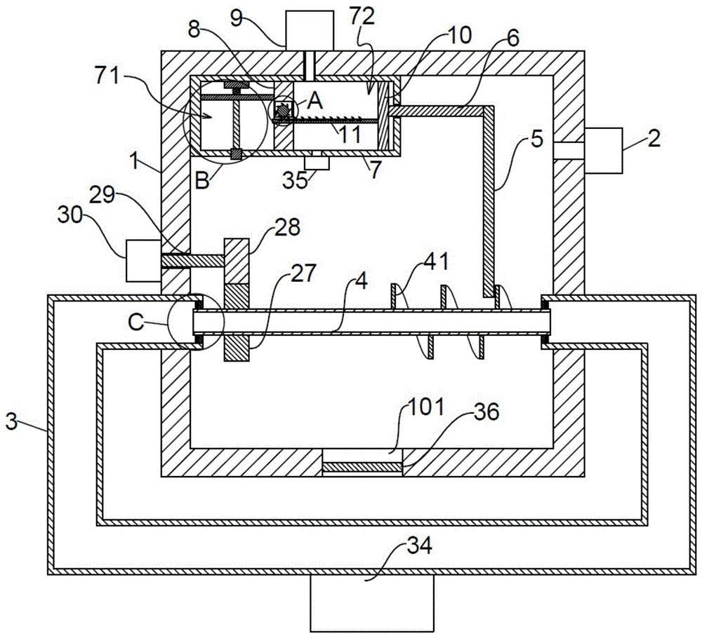
图2为本发明的整体结构剖视示意图;Figure 2 is a schematic cross-sectional view of the overall structure of the present invention;
图3为图2中A区结构放大示意图;Fig. 3 is the enlarged schematic diagram of the structure of A area in Fig. 2;
图4为图2中B区结构放大示意图;Fig. 4 is the enlarged schematic diagram of the structure of B area in Fig. 2;
图5为图2中C区结构放大示意图;Fig. 5 is the enlarged schematic diagram of the structure of C area in Fig. 2;
图6为本发明的转盘控制通气挡板运动示意图。FIG. 6 is a schematic diagram of the movement of the turntable controlling the ventilation baffle according to the present invention.
图中:1反应箱、101出料口、2送氧机、3循环冷却管、301限位环一、4转动冷却管、41螺旋叶片、42限位环二、5推动杆、6连接杆、7液化喷射箱、71液化腔、72送气压缩腔、8隔板、81穿过槽、82空槽、83通气槽、9送二氧化氮机、10活塞、11棘齿板、1101翻转槽、12棘轮、13转盘、131转动块、14同转杆、15棘爪、16棘齿、17转轮一、18复位弹簧一、19配合杆、191配合块、20通气挡板、21挤压弹簧、22电磁铁、23喷射弹簧、24喷射推板、25连杆、26喷口挡块、27从转轮、28主转轮、29驱动杆、30变向电机、31转轮二、32限位块、33复位弹簧二、34循环冷却机、35吸气泵、36出料阀门。In the picture: 1 reaction box, 101 discharge port, 2 oxygen feeder, 3 circulating cooling pipe, 301 limit ring 1, 4 rotating cooling pipe, 41 spiral blade, 42
具体实施方式Detailed ways
下面将结合本发明实施例中的附图,对本发明实施例中的技术方案进行清楚、完整地描述,显然,所描述的实施例仅仅是本发明一部分实施例,而不是全部的实施例。基于本发明中的实施例,本领域普通技术人员在没有做出创造性劳动前提下所获得的所有其他实施例,都属于本发明保护的范围。The technical solutions in the embodiments of the present invention will be clearly and completely described below with reference to the accompanying drawings in the embodiments of the present invention. Obviously, the described embodiments are only a part of the embodiments of the present invention, but not all of the embodiments. Based on the embodiments of the present invention, all other embodiments obtained by those of ordinary skill in the art without creative efforts shall fall within the protection scope of the present invention.
请参阅图1-6,本发明提供一种技术方案:Please refer to Figures 1-6, the present invention provides a technical solution:
一种用于二氧化氮硝化反应的装置,包括反应箱1、输氧单元、转动冷却单元和输二氧化氮单元,输氧单元包括送氧机2,送氧机2与反应箱1连通,送氧机2为硝化反应提供氧气;A device for nitrogen dioxide nitration reaction, comprising a reaction box 1, an oxygen delivery unit, a rotating cooling unit and a nitrogen dioxide delivery unit, the oxygen delivery unit includes an
转动冷却单元包括循环冷却管3和转动冷却管4,转动冷却管4位于反应箱1内部,转动冷却管4对反应箱1中的液体起到降温冷却作用,防止反应温度过高影响反应效率,转动冷却管4由变向电机30驱动,转动冷却管4在变向电机30驱动下做周期性正反转,且转动冷却管4一端固定连接有螺旋叶片41,转动冷却管4转动带动螺旋叶片41转动,螺旋叶片41转动搅拌反应液体,使得反应液体均匀冷却散热,提高反应效率,循环冷却管3与转动冷却管4活动连接;The rotating cooling unit includes a circulating
输二氧化氮单元包括推动杆5、液化喷射箱7、隔板8和送二氧化氮机9,液化喷射箱7固定设置在反应箱1内部,隔板8将液化喷射箱7分隔为左右布置的液化腔71和送气压缩腔72,且送气压缩腔72位于液化腔71和螺旋叶片41之间,送二氧化氮机9与送气压缩腔72连通,送二氧化氮机9为硝化反应提供二氧化氮;The nitrogen dioxide transporting unit includes a
推动杆5活动设置在螺旋叶片41之间,螺旋叶片41转动带动推动杆5做周期性靠近、远离送气压缩腔72的运动,送气压缩腔72内活动连接有活塞10,且推动杆5与活塞10间通过连接杆6固定连接,当推动杆5向靠近送气压缩腔72的方向运动时,推动杆5通过连接杆6带动活塞10向靠近隔板8的方向运动,活塞10挤压送气压缩腔72中的气体,并将二氧化氮挤入液化腔71;The
隔板8内部开设有穿过槽81、空槽82和通气槽83,且穿过槽81、通气槽83均与空槽82连通,活塞10固定连接有棘齿板11,活塞10运动带动棘齿板11运动,且棘齿板11活动伸出穿过槽81,空槽82内活动设置有与棘齿板11配合的棘轮12,当棘齿板11向靠近液化腔71的方向运动时,棘齿板11带动棘轮12转动,当棘齿板11向远离液化腔71的方向运动时,棘轮12在棘爪15限制下无法转动,棘轮12一侧固定连接有同转杆14,同转杆14远离棘轮12的一端固定连接有转盘13,棘轮12转动带动转盘13转动,转盘13上固定连接有若干转动块131;The partition plate 8 is provided with a through
转盘13远离螺旋叶片41的一侧活动设置有配合杆19,配合杆19一侧固定连接有与转动块131配合的配合块191,转动块131转动推动配合块191,使得配合杆19向远离通气槽83的方向运动,配合杆19靠近通气槽83的一端固定连接有通气挡板20,且通气挡板20活动伸入通气槽83,配合杆19运动带动通气挡板20向远离通气槽83的方向运动,使得通气挡板20离开通气槽83,送气压缩腔72中的二氧化氮气体通过通气槽83进入液化腔71中,配合杆19远离通气槽83的一端与空槽82内壁间固定连接有挤压弹簧21,当转盘13停止运动时,转动块131不再挤压配合块191,配合杆19在挤压弹簧21作用下向靠近通气槽83的方向运动,使得通气挡板20挡住通气槽83,防止液化腔71中的气体进入送气压缩腔72中使得液化效果降低;The side of the
棘轮12一侧活动设置有棘爪15,棘爪15对棘轮12起到限位作用,使得棘轮12只能在棘齿板11向靠近液化腔71方向运动时转动,棘齿板11上开设有若干翻转槽1101,翻转槽1101远离液化腔71的一侧内部活动设置有棘齿16,使得棘齿16向靠近液化腔71的方向运动时被翻转槽1101内壁挡住,棘齿16无法翻转,只能推动棘轮12转动,棘齿16与翻转槽1101底壁间通过转轮一17活动连接,当棘齿板11向远离液化腔71的方向运动时,棘轮12被棘爪15卡住,棘齿板11上的棘齿16在棘轮12的棘齿挤压下翻转进入翻转槽1101中并通过棘轮12,且棘齿16与翻转槽1101内壁间固定连接有复位弹簧一18,复位弹簧一18对棘齿16翻转后进行复位;One side of the
液化腔71内固定设置有电磁铁22,电磁铁22靠近液化腔71开口的一侧固定连接有喷射弹簧23,喷射弹簧23远离电磁铁22的一侧固定连接有喷射推板24,电磁铁22通电吸引喷射推板24,使得喷射弹簧23被压缩,电磁铁22断电失去磁性,喷射推板24在喷射弹簧23作用下向靠近液化腔71开口方向运动并将液化后的二氧化氮射进反应液体中进行反应,采用间隔开关电磁铁22可随时根据需要向反应液体中补充二氧化氮,提高生产的灵活性,且将二氧化氮液体喷射进反应液体的方式使得混合更为均匀,提高反应效率,同时部分二氧化氮液体在喷射过程中汽化吸热,进一步提高冷却效果,液化腔71开口内部活动穿过有喷口挡块26,喷口挡块26使得液化腔71在的液体无法流出,且喷射推板24与喷口挡块26通过连杆25固定连接,当喷射推板24向靠近液化腔71开口方向运动时,喷口挡块26离开液化腔71开口,使得液体喷出。The
具体的,转动冷却管4外侧固定套设有从转轮27,从转轮27啮合连接有主转轮28,主转轮28与变向电机30间固定连接有驱动杆29,使得变向电机30带动转动冷却管4做周期性正反转,循环冷却管3端口内部固定连接有限位环一301,转动冷却管4活动伸进循环冷却管3的一端外侧固定连接有限位环二42,限位环一301和限位环二42的设置使得转动冷却管4可在循环冷却管3中自由转动,循环冷却管3外侧固定设置有循环冷却机34,循环冷却机34使得循环冷却管3中的冷却液循环流动并带出反应箱1中的热量。Specifically, a
具体的,棘爪15远离棘轮12的一端通过转轮二31与空槽82内壁活动连接,且棘爪15远离棘轮12棘齿弯曲方向的一侧固定设置有限位块32,且棘爪15与空槽内壁间固定连接有复位弹簧二33,当棘齿板11向靠近液化腔71方向运动时,棘轮12转动挤压棘爪15,使得棘爪15转动,当棘齿板11向远离液化腔71方向运动时,棘轮12转动挤压棘爪15,而棘爪15被限位块32挡住无法转动,棘爪15卡住棘轮12,使得棘轮12无法转动。Specifically, one end of the
具体的,反应箱1开设有出料口101,出料口101内部固定设置有出料阀门36,反应完成后出料阀门36打开,产品通过出料口101排出,送气压缩腔72连通有吸气泵35,当反应完成后,吸气泵35工作将反应箱1中残余的二氧化氮和生成的一氧化氮吸入送气压缩腔72中,一氧化氮在氧气条件下可氧化生成二氧化氮,实现资源再利用和防止环境污染。Specifically, the reaction box 1 is provided with a
工作原理:转动冷却管4转动带动螺旋叶片41转动,螺旋叶片41转动带动推动杆5做周期性靠近、远离送气压缩腔72的运动,当推动杆5向靠近送气压缩腔72的方向运动时,推动杆5通过连接杆6带动活塞10向靠近隔板8的方向运动,活塞10带动棘齿板11向靠近液化腔71的方向运动,棘齿板11带动棘轮12转动,棘轮12转动带动转盘13转动,转动块131转动推动配合块191,使得配合杆19向远离通气槽83的方向运动,配合杆19运动带动通气挡板20离开通气槽83,将送气压缩腔72中的二氧化氮气体通过通气槽83推进液化腔71中;Working principle: the rotation of the cooling pipe 4 drives the
当棘齿板11向远离液化腔71的方向运动时,棘轮12在棘爪15限制下无法转动,转盘13停止运动,转动块131不再挤压配合块191,配合杆19在挤压弹簧21作用下向靠近通气槽83的方向运动,使得通气挡板20挡住通气槽83,棘齿板11上的棘齿16在棘轮12的棘齿挤压下翻转进入翻转槽1101中并通过棘轮12;When the
电磁铁22通电吸引喷射推板24,使得喷射弹簧23被压缩,电磁铁22断电失去磁性,喷射推板24在喷射弹簧23作用下向靠近液化腔71开口方向运动,并将液化后的二氧化氮射进反应液体中进行反应。The
尽管已经示出和描述了本发明的实施例,对于本领域的普通技术人员而言,可以理解在不脱离本发明的原理和精神的情况下可以对这些实施例进行多种变化、修改、替换和变型,本发明的范围由所附权利要求及其等同物限定。Although embodiments of the present invention have been shown and described, it will be understood by those skilled in the art that various changes, modifications, and substitutions can be made in these embodiments without departing from the principle and spirit of the invention and modifications, the scope of the present invention is defined by the appended claims and their equivalents.
Claims (3)
Priority Applications (1)
| Application Number | Priority Date | Filing Date | Title |
|---|---|---|---|
| CN202011116414.2A CN112206739B (en) | 2020-10-19 | 2020-10-19 | Device for nitration of nitrogen dioxide |
Applications Claiming Priority (1)
| Application Number | Priority Date | Filing Date | Title |
|---|---|---|---|
| CN202011116414.2A CN112206739B (en) | 2020-10-19 | 2020-10-19 | Device for nitration of nitrogen dioxide |
Publications (2)
| Publication Number | Publication Date |
|---|---|
| CN112206739A CN112206739A (en) | 2021-01-12 |
| CN112206739B true CN112206739B (en) | 2022-04-12 |
Family
ID=74055760
Family Applications (1)
| Application Number | Title | Priority Date | Filing Date |
|---|---|---|---|
| CN202011116414.2A Active CN112206739B (en) | 2020-10-19 | 2020-10-19 | Device for nitration of nitrogen dioxide |
Country Status (1)
| Country | Link |
|---|---|
| CN (1) | CN112206739B (en) |
Families Citing this family (2)
| Publication number | Priority date | Publication date | Assignee | Title |
|---|---|---|---|---|
| CN114130239B (en) * | 2021-11-30 | 2024-05-17 | 山东邦盛达生物科技有限公司 | Microbial feed mixing tank convenient to feed and discharge |
| CN115560225B (en) * | 2022-10-24 | 2025-09-16 | 歌尔科技有限公司 | A head-mounted display device |
Family Cites Families (9)
| Publication number | Priority date | Publication date | Assignee | Title |
|---|---|---|---|---|
| DE102006038897B4 (en) * | 2006-08-18 | 2014-10-16 | Mühlbauer Technology Gmbh | Apparatus for generating a multicomponent mass |
| WO2013113651A1 (en) * | 2012-01-31 | 2013-08-08 | Bayer Intellectual Property Gmbh | Method and system for producing nitrobenzene |
| CN103086892A (en) * | 2012-11-22 | 2013-05-08 | 安徽淮化股份有限公司 | Method for preparing p-nitrochlorobenzene by nitrifying chlorobenzene by using nitrogen dioxide |
| DE102015106617B4 (en) * | 2014-07-07 | 2017-09-21 | Josef Meissner Gmbh & Co. Kg | Process for the purification of crude dinitrotoluenes |
| CN107096420A (en) * | 2017-05-06 | 2017-08-29 | 六安双收技术转移服务有限公司 | A kind of soft magnetism composite materials device for formulating |
| CN207614733U (en) * | 2017-12-01 | 2018-07-17 | 湛江市晋盛牧业科技有限公司 | One kind being convenient for clean agricultural blender |
| CN208061367U (en) * | 2018-03-27 | 2018-11-06 | 浙江红彤电气有限公司 | A kind of power transformer with anti-theft alarm function |
| CN108947848A (en) * | 2018-08-07 | 2018-12-07 | 安庆市长虹化工有限公司 | A kind of nitrification installation and nitration processes method of o-nitrobenzaldehyde preparation |
| CN111573758B (en) * | 2020-06-10 | 2021-01-12 | 山东锦沐新材料科技有限公司 | Wastewater treatment device capable of controlling dosage of medicament |
-
2020
- 2020-10-19 CN CN202011116414.2A patent/CN112206739B/en active Active
Also Published As
| Publication number | Publication date |
|---|---|
| CN112206739A (en) | 2021-01-12 |
Similar Documents
| Publication | Publication Date | Title |
|---|---|---|
| CN112206739B (en) | Device for nitration of nitrogen dioxide | |
| DE60115211T2 (en) | POWER MACHINE AND METHOD FOR GENERATING WAVE POWER | |
| CN217230305U (en) | A high-pressure micro-nano aeration type microwave sewage treatment device | |
| CN216757491U (en) | Intelligent dry ice cleaning equipment | |
| CN208375670U (en) | A kind of fire retardant master batch hot granulator | |
| CN111773883A (en) | Paper mill exhaust treatment device that treatment effect is good | |
| CN118529834B (en) | Sewage treatment is with automatic medicine device that adds | |
| CN219459702U (en) | Soil improvement equipment with high-efficient microorganism | |
| CN115818044A (en) | A diketene cooling storage device and method | |
| CN116421989B (en) | A high-efficiency MVR continuous circulation evaporation equipment | |
| CN216343843U (en) | Animal remedy production is with wire drawing filling and sealing machine bevel gear reversing mechanism | |
| CN210681119U (en) | Water-cooled refrigerated container ship of LNG fuel | |
| CN120907261B (en) | A unit and process for recovering high-pressure fluid energy for liquid cooling and washing. | |
| CN223069510U (en) | A kind of methyl carbamate synthesis equipment | |
| CN207207063U (en) | A kind of PE pipe production devices | |
| CN223147687U (en) | Quick circulation cooling's magnetic force building blocks injection moulding machine | |
| CN221825712U (en) | Freeze dryer for pigment production | |
| CN223909278U (en) | An intermediate tank with its own cooling device | |
| CN218702949U (en) | Liquid ethane transportation semitrailer with cooling function | |
| CN116160642B (en) | Electric mould locking device of high-speed injection molding machine | |
| CN209240471U (en) | A kind of novel rubber plastic product shaping equipment of automatic stocking | |
| CN209663061U (en) | A kind of nitric acid configuration device | |
| CN221484352U (en) | Medicine mixing arrangement is used in production of column bullet | |
| CN222681777U (en) | An air supply structure for an anti-corrosion internal molding machine of a fire extinguisher | |
| CN223864207U (en) | Quick cooling type front-row chair back plate injection mold |
Legal Events
| Date | Code | Title | Description |
|---|---|---|---|
| PB01 | Publication | ||
| PB01 | Publication | ||
| SE01 | Entry into force of request for substantive examination | ||
| SE01 | Entry into force of request for substantive examination | ||
| GR01 | Patent grant | ||
| GR01 | Patent grant |