CN112203578A - Sensor and device for determining at least one parameter of blood circulating in an extracorporeal blood circuit - Google Patents
Sensor and device for determining at least one parameter of blood circulating in an extracorporeal blood circuit Download PDFInfo
- Publication number
- CN112203578A CN112203578A CN201980034190.XA CN201980034190A CN112203578A CN 112203578 A CN112203578 A CN 112203578A CN 201980034190 A CN201980034190 A CN 201980034190A CN 112203578 A CN112203578 A CN 112203578A
- Authority
- CN
- China
- Prior art keywords
- blood
- conductivity
- dialysate
- extracorporeal
- sensor
- Prior art date
- Legal status (The legal status is an assumption and is not a legal conclusion. Google has not performed a legal analysis and makes no representation as to the accuracy of the status listed.)
- Granted
Links
Images


Classifications
-
- A—HUMAN NECESSITIES
- A61—MEDICAL OR VETERINARY SCIENCE; HYGIENE
- A61M—DEVICES FOR INTRODUCING MEDIA INTO, OR ONTO, THE BODY; DEVICES FOR TRANSDUCING BODY MEDIA OR FOR TAKING MEDIA FROM THE BODY; DEVICES FOR PRODUCING OR ENDING SLEEP OR STUPOR
- A61M1/00—Suction or pumping devices for medical purposes; Devices for carrying-off, for treatment of, or for carrying-over, body-liquids; Drainage systems
- A61M1/36—Other treatment of blood in a by-pass of the natural circulatory system, e.g. temperature adaptation, irradiation ; Extra-corporeal blood circuits
-
- A—HUMAN NECESSITIES
- A61—MEDICAL OR VETERINARY SCIENCE; HYGIENE
- A61B—DIAGNOSIS; SURGERY; IDENTIFICATION
- A61B5/00—Measuring for diagnostic purposes; Identification of persons
- A61B5/02—Detecting, measuring or recording for evaluating the cardiovascular system, e.g. pulse, heart rate, blood pressure or blood flow
- A61B5/026—Measuring blood flow
- A61B5/0261—Measuring blood flow using optical means, e.g. infrared light
-
- A—HUMAN NECESSITIES
- A61—MEDICAL OR VETERINARY SCIENCE; HYGIENE
- A61B—DIAGNOSIS; SURGERY; IDENTIFICATION
- A61B5/00—Measuring for diagnostic purposes; Identification of persons
- A61B5/0059—Measuring for diagnostic purposes; Identification of persons using light, e.g. diagnosis by transillumination, diascopy, fluorescence
- A61B5/0071—Measuring for diagnostic purposes; Identification of persons using light, e.g. diagnosis by transillumination, diascopy, fluorescence by measuring fluorescence emission
-
- A—HUMAN NECESSITIES
- A61—MEDICAL OR VETERINARY SCIENCE; HYGIENE
- A61B—DIAGNOSIS; SURGERY; IDENTIFICATION
- A61B5/00—Measuring for diagnostic purposes; Identification of persons
- A61B5/0059—Measuring for diagnostic purposes; Identification of persons using light, e.g. diagnosis by transillumination, diascopy, fluorescence
- A61B5/0075—Measuring for diagnostic purposes; Identification of persons using light, e.g. diagnosis by transillumination, diascopy, fluorescence by spectroscopy, i.e. measuring spectra, e.g. Raman spectroscopy, infrared absorption spectroscopy
-
- A—HUMAN NECESSITIES
- A61—MEDICAL OR VETERINARY SCIENCE; HYGIENE
- A61B—DIAGNOSIS; SURGERY; IDENTIFICATION
- A61B5/00—Measuring for diagnostic purposes; Identification of persons
- A61B5/145—Measuring characteristics of blood in vivo, e.g. gas concentration or pH-value ; Measuring characteristics of body fluids or tissues, e.g. interstitial fluid or cerebral tissue
- A61B5/14535—Measuring characteristics of blood in vivo, e.g. gas concentration or pH-value ; Measuring characteristics of body fluids or tissues, e.g. interstitial fluid or cerebral tissue for measuring haematocrit
-
- A—HUMAN NECESSITIES
- A61—MEDICAL OR VETERINARY SCIENCE; HYGIENE
- A61B—DIAGNOSIS; SURGERY; IDENTIFICATION
- A61B5/00—Measuring for diagnostic purposes; Identification of persons
- A61B5/145—Measuring characteristics of blood in vivo, e.g. gas concentration or pH-value ; Measuring characteristics of body fluids or tissues, e.g. interstitial fluid or cerebral tissue
- A61B5/14546—Measuring characteristics of blood in vivo, e.g. gas concentration or pH-value ; Measuring characteristics of body fluids or tissues, e.g. interstitial fluid or cerebral tissue for measuring analytes not otherwise provided for, e.g. ions, cytochromes
-
- A—HUMAN NECESSITIES
- A61—MEDICAL OR VETERINARY SCIENCE; HYGIENE
- A61B—DIAGNOSIS; SURGERY; IDENTIFICATION
- A61B5/00—Measuring for diagnostic purposes; Identification of persons
- A61B5/145—Measuring characteristics of blood in vivo, e.g. gas concentration or pH-value ; Measuring characteristics of body fluids or tissues, e.g. interstitial fluid or cerebral tissue
- A61B5/1455—Measuring characteristics of blood in vivo, e.g. gas concentration or pH-value ; Measuring characteristics of body fluids or tissues, e.g. interstitial fluid or cerebral tissue using optical sensors, e.g. spectral photometrical oximeters
- A61B5/14551—Measuring characteristics of blood in vivo, e.g. gas concentration or pH-value ; Measuring characteristics of body fluids or tissues, e.g. interstitial fluid or cerebral tissue using optical sensors, e.g. spectral photometrical oximeters for measuring blood gases
- A61B5/14557—Measuring characteristics of blood in vivo, e.g. gas concentration or pH-value ; Measuring characteristics of body fluids or tissues, e.g. interstitial fluid or cerebral tissue using optical sensors, e.g. spectral photometrical oximeters for measuring blood gases specially adapted to extracorporeal circuits
-
- A—HUMAN NECESSITIES
- A61—MEDICAL OR VETERINARY SCIENCE; HYGIENE
- A61B—DIAGNOSIS; SURGERY; IDENTIFICATION
- A61B5/00—Measuring for diagnostic purposes; Identification of persons
- A61B5/68—Arrangements of detecting, measuring or recording means, e.g. sensors, in relation to patient
- A61B5/6846—Arrangements of detecting, measuring or recording means, e.g. sensors, in relation to patient specially adapted to be brought in contact with an internal body part, i.e. invasive
- A61B5/6847—Arrangements of detecting, measuring or recording means, e.g. sensors, in relation to patient specially adapted to be brought in contact with an internal body part, i.e. invasive mounted on an invasive device
- A61B5/6866—Extracorporeal blood circuits, e.g. dialysis circuits
-
- A—HUMAN NECESSITIES
- A61—MEDICAL OR VETERINARY SCIENCE; HYGIENE
- A61B—DIAGNOSIS; SURGERY; IDENTIFICATION
- A61B8/00—Diagnosis using ultrasonic, sonic or infrasonic waves
-
- A—HUMAN NECESSITIES
- A61—MEDICAL OR VETERINARY SCIENCE; HYGIENE
- A61M—DEVICES FOR INTRODUCING MEDIA INTO, OR ONTO, THE BODY; DEVICES FOR TRANSDUCING BODY MEDIA OR FOR TAKING MEDIA FROM THE BODY; DEVICES FOR PRODUCING OR ENDING SLEEP OR STUPOR
- A61M1/00—Suction or pumping devices for medical purposes; Devices for carrying-off, for treatment of, or for carrying-over, body-liquids; Drainage systems
- A61M1/14—Dialysis systems; Artificial kidneys; Blood oxygenators ; Reciprocating systems for treatment of body fluids, e.g. single needle systems for hemofiltration or pheresis
- A61M1/16—Dialysis systems; Artificial kidneys; Blood oxygenators ; Reciprocating systems for treatment of body fluids, e.g. single needle systems for hemofiltration or pheresis with membranes
- A61M1/1601—Control or regulation
- A61M1/1603—Regulation parameters
- A61M1/1605—Physical characteristics of the dialysate fluid
-
- A—HUMAN NECESSITIES
- A61—MEDICAL OR VETERINARY SCIENCE; HYGIENE
- A61M—DEVICES FOR INTRODUCING MEDIA INTO, OR ONTO, THE BODY; DEVICES FOR TRANSDUCING BODY MEDIA OR FOR TAKING MEDIA FROM THE BODY; DEVICES FOR PRODUCING OR ENDING SLEEP OR STUPOR
- A61M1/00—Suction or pumping devices for medical purposes; Devices for carrying-off, for treatment of, or for carrying-over, body-liquids; Drainage systems
- A61M1/14—Dialysis systems; Artificial kidneys; Blood oxygenators ; Reciprocating systems for treatment of body fluids, e.g. single needle systems for hemofiltration or pheresis
- A61M1/16—Dialysis systems; Artificial kidneys; Blood oxygenators ; Reciprocating systems for treatment of body fluids, e.g. single needle systems for hemofiltration or pheresis with membranes
- A61M1/1601—Control or regulation
- A61M1/1613—Profiling or modelling of patient or predicted treatment evolution or outcome
-
- A—HUMAN NECESSITIES
- A61—MEDICAL OR VETERINARY SCIENCE; HYGIENE
- A61M—DEVICES FOR INTRODUCING MEDIA INTO, OR ONTO, THE BODY; DEVICES FOR TRANSDUCING BODY MEDIA OR FOR TAKING MEDIA FROM THE BODY; DEVICES FOR PRODUCING OR ENDING SLEEP OR STUPOR
- A61M1/00—Suction or pumping devices for medical purposes; Devices for carrying-off, for treatment of, or for carrying-over, body-liquids; Drainage systems
- A61M1/14—Dialysis systems; Artificial kidneys; Blood oxygenators ; Reciprocating systems for treatment of body fluids, e.g. single needle systems for hemofiltration or pheresis
- A61M1/16—Dialysis systems; Artificial kidneys; Blood oxygenators ; Reciprocating systems for treatment of body fluids, e.g. single needle systems for hemofiltration or pheresis with membranes
- A61M1/1601—Control or regulation
- A61M1/1617—Control or regulation using measurements made during a temporary variation of a characteristic of the fresh dialysis fluid
-
- A—HUMAN NECESSITIES
- A61—MEDICAL OR VETERINARY SCIENCE; HYGIENE
- A61M—DEVICES FOR INTRODUCING MEDIA INTO, OR ONTO, THE BODY; DEVICES FOR TRANSDUCING BODY MEDIA OR FOR TAKING MEDIA FROM THE BODY; DEVICES FOR PRODUCING OR ENDING SLEEP OR STUPOR
- A61M1/00—Suction or pumping devices for medical purposes; Devices for carrying-off, for treatment of, or for carrying-over, body-liquids; Drainage systems
- A61M1/14—Dialysis systems; Artificial kidneys; Blood oxygenators ; Reciprocating systems for treatment of body fluids, e.g. single needle systems for hemofiltration or pheresis
- A61M1/16—Dialysis systems; Artificial kidneys; Blood oxygenators ; Reciprocating systems for treatment of body fluids, e.g. single needle systems for hemofiltration or pheresis with membranes
- A61M1/1601—Control or regulation
- A61M1/1619—Sampled collection of used dialysate, i.e. obviating the need for recovery of whole dialysate quantity for post-dialysis analysis
-
- A—HUMAN NECESSITIES
- A61—MEDICAL OR VETERINARY SCIENCE; HYGIENE
- A61M—DEVICES FOR INTRODUCING MEDIA INTO, OR ONTO, THE BODY; DEVICES FOR TRANSDUCING BODY MEDIA OR FOR TAKING MEDIA FROM THE BODY; DEVICES FOR PRODUCING OR ENDING SLEEP OR STUPOR
- A61M1/00—Suction or pumping devices for medical purposes; Devices for carrying-off, for treatment of, or for carrying-over, body-liquids; Drainage systems
- A61M1/36—Other treatment of blood in a by-pass of the natural circulatory system, e.g. temperature adaptation, irradiation ; Extra-corporeal blood circuits
- A61M1/3601—Extra-corporeal circuits in which the blood fluid passes more than once through the treatment unit
-
- A—HUMAN NECESSITIES
- A61—MEDICAL OR VETERINARY SCIENCE; HYGIENE
- A61M—DEVICES FOR INTRODUCING MEDIA INTO, OR ONTO, THE BODY; DEVICES FOR TRANSDUCING BODY MEDIA OR FOR TAKING MEDIA FROM THE BODY; DEVICES FOR PRODUCING OR ENDING SLEEP OR STUPOR
- A61M1/00—Suction or pumping devices for medical purposes; Devices for carrying-off, for treatment of, or for carrying-over, body-liquids; Drainage systems
- A61M1/36—Other treatment of blood in a by-pass of the natural circulatory system, e.g. temperature adaptation, irradiation ; Extra-corporeal blood circuits
- A61M1/3607—Regulation parameters
- A61M1/3609—Physical characteristics of the blood, e.g. haematocrit, urea
- A61M1/3612—Physical characteristics of the blood, e.g. haematocrit, urea after treatment
-
- A—HUMAN NECESSITIES
- A61—MEDICAL OR VETERINARY SCIENCE; HYGIENE
- A61M—DEVICES FOR INTRODUCING MEDIA INTO, OR ONTO, THE BODY; DEVICES FOR TRANSDUCING BODY MEDIA OR FOR TAKING MEDIA FROM THE BODY; DEVICES FOR PRODUCING OR ENDING SLEEP OR STUPOR
- A61M1/00—Suction or pumping devices for medical purposes; Devices for carrying-off, for treatment of, or for carrying-over, body-liquids; Drainage systems
- A61M1/36—Other treatment of blood in a by-pass of the natural circulatory system, e.g. temperature adaptation, irradiation ; Extra-corporeal blood circuits
- A61M1/3621—Extra-corporeal blood circuits
- A61M1/3663—Flow rate transducers; Flow integrators
-
- A—HUMAN NECESSITIES
- A61—MEDICAL OR VETERINARY SCIENCE; HYGIENE
- A61M—DEVICES FOR INTRODUCING MEDIA INTO, OR ONTO, THE BODY; DEVICES FOR TRANSDUCING BODY MEDIA OR FOR TAKING MEDIA FROM THE BODY; DEVICES FOR PRODUCING OR ENDING SLEEP OR STUPOR
- A61M1/00—Suction or pumping devices for medical purposes; Devices for carrying-off, for treatment of, or for carrying-over, body-liquids; Drainage systems
- A61M1/36—Other treatment of blood in a by-pass of the natural circulatory system, e.g. temperature adaptation, irradiation ; Extra-corporeal blood circuits
- A61M1/3621—Extra-corporeal blood circuits
- A61M1/3669—Electrical impedance measurement of body fluids; transducers specially adapted therefor
-
- A—HUMAN NECESSITIES
- A61—MEDICAL OR VETERINARY SCIENCE; HYGIENE
- A61M—DEVICES FOR INTRODUCING MEDIA INTO, OR ONTO, THE BODY; DEVICES FOR TRANSDUCING BODY MEDIA OR FOR TAKING MEDIA FROM THE BODY; DEVICES FOR PRODUCING OR ENDING SLEEP OR STUPOR
- A61M1/00—Suction or pumping devices for medical purposes; Devices for carrying-off, for treatment of, or for carrying-over, body-liquids; Drainage systems
- A61M1/36—Other treatment of blood in a by-pass of the natural circulatory system, e.g. temperature adaptation, irradiation ; Extra-corporeal blood circuits
- A61M1/3621—Extra-corporeal blood circuits
- A61M1/367—Circuit parts not covered by the preceding subgroups of group A61M1/3621
-
- A—HUMAN NECESSITIES
- A61—MEDICAL OR VETERINARY SCIENCE; HYGIENE
- A61B—DIAGNOSIS; SURGERY; IDENTIFICATION
- A61B2560/00—Constructional details of operational features of apparatus; Accessories for medical measuring apparatus
- A61B2560/04—Constructional details of apparatus
- A61B2560/0462—Apparatus with built-in sensors
-
- A—HUMAN NECESSITIES
- A61—MEDICAL OR VETERINARY SCIENCE; HYGIENE
- A61B—DIAGNOSIS; SURGERY; IDENTIFICATION
- A61B2562/00—Details of sensors; Constructional details of sensor housings or probes; Accessories for sensors
-
- A—HUMAN NECESSITIES
- A61—MEDICAL OR VETERINARY SCIENCE; HYGIENE
- A61B—DIAGNOSIS; SURGERY; IDENTIFICATION
- A61B2562/00—Details of sensors; Constructional details of sensor housings or probes; Accessories for sensors
- A61B2562/02—Details of sensors specially adapted for in-vivo measurements
- A61B2562/0233—Special features of optical sensors or probes classified in A61B5/00
-
- A—HUMAN NECESSITIES
- A61—MEDICAL OR VETERINARY SCIENCE; HYGIENE
- A61B—DIAGNOSIS; SURGERY; IDENTIFICATION
- A61B2562/00—Details of sensors; Constructional details of sensor housings or probes; Accessories for sensors
- A61B2562/04—Arrangements of multiple sensors of the same type
-
- A—HUMAN NECESSITIES
- A61—MEDICAL OR VETERINARY SCIENCE; HYGIENE
- A61B—DIAGNOSIS; SURGERY; IDENTIFICATION
- A61B2562/00—Details of sensors; Constructional details of sensor housings or probes; Accessories for sensors
- A61B2562/14—Coupling media or elements to improve sensor contact with skin or tissue
- A61B2562/146—Coupling media or elements to improve sensor contact with skin or tissue for optical coupling
-
- A—HUMAN NECESSITIES
- A61—MEDICAL OR VETERINARY SCIENCE; HYGIENE
- A61B—DIAGNOSIS; SURGERY; IDENTIFICATION
- A61B2562/00—Details of sensors; Constructional details of sensor housings or probes; Accessories for sensors
- A61B2562/16—Details of sensor housings or probes; Details of structural supports for sensors
- A61B2562/164—Details of sensor housings or probes; Details of structural supports for sensors the sensor is mounted in or on a conformable substrate or carrier
-
- A—HUMAN NECESSITIES
- A61—MEDICAL OR VETERINARY SCIENCE; HYGIENE
- A61B—DIAGNOSIS; SURGERY; IDENTIFICATION
- A61B2562/00—Details of sensors; Constructional details of sensor housings or probes; Accessories for sensors
- A61B2562/16—Details of sensor housings or probes; Details of structural supports for sensors
- A61B2562/166—Details of sensor housings or probes; Details of structural supports for sensors the sensor is mounted on a specially adapted printed circuit board
-
- A—HUMAN NECESSITIES
- A61—MEDICAL OR VETERINARY SCIENCE; HYGIENE
- A61B—DIAGNOSIS; SURGERY; IDENTIFICATION
- A61B2562/00—Details of sensors; Constructional details of sensor housings or probes; Accessories for sensors
- A61B2562/22—Arrangements of medical sensors with cables or leads; Connectors or couplings specifically adapted for medical sensors
- A61B2562/225—Connectors or couplings
- A61B2562/228—Sensors with optical connectors
-
- A—HUMAN NECESSITIES
- A61—MEDICAL OR VETERINARY SCIENCE; HYGIENE
- A61M—DEVICES FOR INTRODUCING MEDIA INTO, OR ONTO, THE BODY; DEVICES FOR TRANSDUCING BODY MEDIA OR FOR TAKING MEDIA FROM THE BODY; DEVICES FOR PRODUCING OR ENDING SLEEP OR STUPOR
- A61M2205/00—General characteristics of the apparatus
- A61M2205/33—Controlling, regulating or measuring
- A61M2205/3306—Optical measuring means
-
- A—HUMAN NECESSITIES
- A61—MEDICAL OR VETERINARY SCIENCE; HYGIENE
- A61M—DEVICES FOR INTRODUCING MEDIA INTO, OR ONTO, THE BODY; DEVICES FOR TRANSDUCING BODY MEDIA OR FOR TAKING MEDIA FROM THE BODY; DEVICES FOR PRODUCING OR ENDING SLEEP OR STUPOR
- A61M2205/00—General characteristics of the apparatus
- A61M2205/33—Controlling, regulating or measuring
- A61M2205/3331—Pressure; Flow
- A61M2205/3334—Measuring or controlling the flow rate
-
- A—HUMAN NECESSITIES
- A61—MEDICAL OR VETERINARY SCIENCE; HYGIENE
- A61M—DEVICES FOR INTRODUCING MEDIA INTO, OR ONTO, THE BODY; DEVICES FOR TRANSDUCING BODY MEDIA OR FOR TAKING MEDIA FROM THE BODY; DEVICES FOR PRODUCING OR ENDING SLEEP OR STUPOR
- A61M2205/00—General characteristics of the apparatus
- A61M2205/50—General characteristics of the apparatus with microprocessors or computers
-
- A—HUMAN NECESSITIES
- A61—MEDICAL OR VETERINARY SCIENCE; HYGIENE
- A61M—DEVICES FOR INTRODUCING MEDIA INTO, OR ONTO, THE BODY; DEVICES FOR TRANSDUCING BODY MEDIA OR FOR TAKING MEDIA FROM THE BODY; DEVICES FOR PRODUCING OR ENDING SLEEP OR STUPOR
- A61M2230/00—Measuring parameters of the user
- A61M2230/20—Blood composition characteristics
- A61M2230/207—Blood composition characteristics hematocrit
-
- A—HUMAN NECESSITIES
- A61—MEDICAL OR VETERINARY SCIENCE; HYGIENE
- A61M—DEVICES FOR INTRODUCING MEDIA INTO, OR ONTO, THE BODY; DEVICES FOR TRANSDUCING BODY MEDIA OR FOR TAKING MEDIA FROM THE BODY; DEVICES FOR PRODUCING OR ENDING SLEEP OR STUPOR
- A61M2230/00—Measuring parameters of the user
- A61M2230/65—Impedance, e.g. conductivity, capacity
Landscapes
- Health & Medical Sciences (AREA)
- Life Sciences & Earth Sciences (AREA)
- Heart & Thoracic Surgery (AREA)
- Veterinary Medicine (AREA)
- Public Health (AREA)
- Engineering & Computer Science (AREA)
- General Health & Medical Sciences (AREA)
- Biomedical Technology (AREA)
- Animal Behavior & Ethology (AREA)
- Physics & Mathematics (AREA)
- Vascular Medicine (AREA)
- Hematology (AREA)
- Anesthesiology (AREA)
- Surgery (AREA)
- Biophysics (AREA)
- Pathology (AREA)
- Medical Informatics (AREA)
- Molecular Biology (AREA)
- Urology & Nephrology (AREA)
- Cardiology (AREA)
- Emergency Medicine (AREA)
- Spectroscopy & Molecular Physics (AREA)
- Optics & Photonics (AREA)
- Physiology (AREA)
- Nuclear Medicine, Radiotherapy & Molecular Imaging (AREA)
- Radiology & Medical Imaging (AREA)
- Fluid Mechanics (AREA)
- External Artificial Organs (AREA)
- Measuring And Recording Apparatus For Diagnosis (AREA)
- Investigating Or Analysing Biological Materials (AREA)
- Measurement Of The Respiration, Hearing Ability, Form, And Blood Characteristics Of Living Organisms (AREA)
Abstract
An apparatus (1) for extracorporeal treatment of blood comprising: a treatment unit (2), a blood withdrawal line (6), a blood return line (7), a preparation line (19) and a spent dialysate line (13); non-invasive blood volume sensor (50) for determining activity on a tubing segment (61) of a blood withdrawal line or a blood return lineAdditional characteristics of the blood of (a); the sensor includes: a source (53) for directing signals to the blood; a plurality of detectors (57) for receiving signals; and a controller (65) that receives the output signal from the detector (57) and determines a blood volume change and a sodium concentration (Na) in blood based on the output signalpl) The value of (c). A process of determining at least one parameter and characteristic of blood circulating in an extracorporeal blood circuit is also disclosed.
Description
Technical Field
The invention relates to a device, a sensor and a process for determining at least one parameter of blood circulating in an extracorporeal blood circuit. In particular, the device, sensor and process of the invention can be used for the non-invasive measurement of the relative blood volume change (Δ RBV) of plasma or blood circulating in an extracorporeal circuit, and in more detail for the percentage of relative blood volume change (Δ RBV%) and/or the blood or plasma sodium concentration (Na)pl) And/or electrical conductivity. In more detail, the present invention is directed to the online measurement of blood parameters during extracorporeal blood treatment or during extracorporeal plasma treatment (e.g., hemodialysis, hemofiltration, hemodiafiltration, plasmapheresis, etc.). The invention also relates to an apparatus and a method for determining a parameter indicative of the progress of an extracorporeal blood treatment, in particular a purification treatment, with the aim of alleviating renal insufficiency, for example hemodialysis or hemodiafiltration, based on a measurement of a blood or plasma parameter.
Although the apparatus, sensor and process of the present invention may be applied to any extracorporeal blood or plasma treatment, in this context we will mainly refer to treatments such as hemodialysis or hemofiltration or hemodiafiltration, by way of example.
Hemodialysis is a treatment for patients with chronic kidney injury, and is typically performed 3-4 times a week for 3-5 hours. This treatment has three main goals, wherein the first goal is to remove excess body water accumulated between dialysis, which is achieved by Ultrafiltration (UF). The second objective is to remove uremic toxins that also accumulate between dialysis sessions. A third objective is to restore the proper balance of electrolytes in the blood.
In hemodialysis treatment, the patient's blood and a treatment fluid that is substantially isotonic with the blood flow circulate in the respective compartments of a hemodialyzer, so that impurities and undesired substances present in the blood (urea, creatinine, etc.) can pass from the blood into the treatment fluid by diffusive transport. The ion concentration of the treatment fluid is selected to correct the ion concentration of the patient's blood. In other words, hemodialysis is based on two phenomena of dispersion and convection, by which substance transport of water and solutes across the membrane of a hemodialysis filter (hemodialyzer) is achieved. Hemodialyzers are cylindrical bundles of hollow fibers designed to maximize the exchange surface area. Inside, the blood and the dialysis fluid (dialysate) flow in countercurrent on opposite sides of the membrane.
In hemofiltration, convective transport by ultrafiltration occurs across the semipermeable membrane of the hemofilter. In the treatment by hemodiafiltration, the convective transport by ultrafiltration, caused by the positive pressure difference generated between the blood side and the treatment liquid side of the semipermeable membrane, adds to the diffusive transport obtained by dialysis.
In these types of processes, it is of interest to be able to determine one or more parameters indicating how the process affects or has affected the blood of the process. On the other hand, on-line monitoring of certain blood parameters may allow modification of the initially fixed treatment conditions, or at least inform the patient and medical staff of the progress of the treatment.
Knowledge of one or more of the following parameters may allow tracking of the progress of the process, thereby helping to assess the suitability of the initially fixed process conditions, or to determine whether the processing unit is functioning adequately or to assess the presence of recirculation through the pathway:
-the concentration of one or more electrolytes in extracorporeal blood or plasma,
-the conductivity of the extracorporeal blood or plasma,
blood volume changes, e.g. relative blood volume loss during a dialysis procedure,
for a given solute, the actual dialysance D or the actual clearance K of the exchanger (dialysance D and clearance K representing the purification efficiency of the exchanger),
the Dialysis dose administered after the treatment time t, which according to the work of Sargent and Gotch can be related to a dimensionless ratio Kt/V, where K is the actual clearance of urea, t is the elapsed treatment time and V is the volume of distribution of urea, i.e. the total water volume in the patient (Gotch f.a. and Sargent s.a. published in renal international (1985) volume 28, pp.526-34 of "a mechanistic analysis of the National Cooperative Dialysis Study (NCDS)").
Determining the above parameters requires accurate knowledge of the physical or chemical characteristics of the blood or plasma.
It will be appreciated that in principle this characteristic can be determined by direct measurement of a blood sample. However, for therapeutic, prophylactic and financial reasons, it is not possible to collect multiple specimens from patients who are often anemic to monitor the effectiveness of the treatment. Furthermore, in view of the risks associated with processing blood samples that may be contaminated, the general trend is to avoid such processing operations; finally, laboratory analysis of blood samples is both expensive and relatively lengthy, which is incompatible with the desired goal of understanding the effectiveness of the treatment while it is still in progress.
In modern hemodialysis, great attention has been paid to the development of non-invasive methods for collecting physiological information by applying sensors directly to the patient or accessing the hemodialysis machine during the procedure. In addition to being important for patient safety and gathering clinical knowledge, continuous or semi-continuous monitoring of physiological parameters is particularly important as an input to a biofeedback system.
Examples of physiological parameters under investigation are the relative blood volume change (Δ RBV%), the dialysis rate (D) and the plasma conductivity (σ)Pl). Amount of blood volume change (. DELTA.RBV)The effect of UF was quantified and is today continuously monitored by optical or ultrasonic means. Parameter D quantifies dialysis efficiency and may change during treatment. SigmaPlSubstituted plasma sodium concentration NaPl(which currently cannot be measured in a direct, continuous and non-invasive manner).
Several known methods have been proposed for determining blood concentration or other hemodialysis parameters (e.g., blood volume change and plasma conductivity) in vivo without having to measure a blood sample.
For example, using a urea sensor in the spent dialysate line, the urea concentration in the blood can be calculated. However, urea sensors are complex, expensive and may not result in accurate measurements.
According to the second method, the blood conductivity or blood electrolyte concentration can be measured by: a periodic variation of the concentration of a given substance or a periodic variation of the conductivity of the dialysate is applied at the inlet of the blood treatment unit (filter or hemodialyzer) and the corresponding effect is measured by the concentration or conductivity variation of the same substance in the spent dialysate. The following patent references disclose methods for determining in vivo the blood conductivity, blood concentration of a given substance, dialysis rate and other parameters disturbing fresh dialysate, as well as methods for making concentration/conductivity measurements on the dialysate side of the device: EP 0547025, EP 0658352, EP 0920877, US 2001004523, EP 2687248, US 6187199, US 5100554. A problem with the second type of method is that the composition of the fresh dialysis fluid needs to be perturbed in order to subsequently determine the sought parameters, such as the sodium concentration in the blood and/or the sodium dialysance, by more or less complex calculations. Furthermore, it may be difficult to measure the concentration/conductivity in the liquid downstream of the dialyzer with high accuracy. Moreover, hydraulic delays, damping effects caused by the dialyzer, and noise introduced by the machine and its components may need to appropriately refine the signal detected by the sensors. In addition, all of the above methods require calculations that may be relatively complex before the blood sodium concentration or blood conductivity can be determined.
Finally, US8525533 uses a conductivity sensor which is applied to the spent dialysate line and is able to determine the conductivity of the spent dialysate. According to this reference, the conductivity sensor requires four electrodes, namely two annular excitation electrodes and two annular pickup electrodes (pick-up electrodes). When the sensor is applied to a dialysate line, one of the above disclosed methods with the just described drawbacks will have to be employed in order to determine the blood parameters.
Referring now to the relative blood volume change (Δ RBV), online measurement of this particular blood parameter typically uses optical methods. Optical Δ RBV estimation is based on the absorbance of hemoglobin (Hgb), which is almost completely contained inside the red blood cells. In a simple optical sensor, an LED and photodiode are used to detect changes in absorbance that correlate with changes in red blood cell concentration. During the treatment, the number of erythrocytes is almost constant, so that the blood concentration is mainly due to the water removal by ultrafiltration, which is greater than the plasma refill rate.
Known sensors can only measure light emitted from an infrared LED that is transmitted through the blood at 180 degrees. This measurement, absorbance, depends on the variation of hematocrit and can therefore be used to estimate the loss of relative blood volume.
Other devices for measuring relative blood volume loss utilize reflectance sensors to measure blood reflectance. In this case, the light emitting LED and the optical sensor are placed at a distance on the same side of the cuvette.
Ultrasonic sensors are also used to measure RBV loss as a function of total protein concentration.
Furthermore, optical systems with multiple LEDs for measurements at different wavelengths are also used for estimating oxygen saturation and for calibration purposes.
The use of optical sensors in blood applications is decentralized, but most implementations use only one measurement channel. When multiple channels are used, it is primarily for the purpose of detecting light at different wavelengths, for purposes such as estimating oxygen saturation or performing additional calibration (e.g., to compensate for the effects of temperature).
Recently, it has been reported that Δ RBV estimation by optical sensors suffers from cross-sensitivity to changes in electrolyte concentration. Abrupt changes in dialysate sodium concentration can lead to underestimation or overestimation of Δ RBV. This change can be explained by considering the effect of osmotic pressure on the volume of the red blood cells. Sodium is one of the most concentrated solutes in both dialysate and plasma, and is the main driver of osmotic pressure. Changes in dialysate sodium are propagated to the plasma due to diffusion across the hemodialysis membrane. Thus, water transfer occurs across the erythrocyte membrane to balance the internal and external osmotic pressures, thereby changing its volume. This volume change changes the local Hgb concentration and results in changes in blood absorption and scattering properties. Although the relationship between blood concentration, osmolarity and blood optical properties is to be studied, the effect of osmolarity on the RBV estimate remains a significant issue to be addressed, since in some treatments, a physician may set a blood volume change target to be reached at the end of the treatment, and the RBV end estimate may be used as feedback to control ultrafiltration to reach the target. Furthermore, in order to improve the health of the patient, huge blood volume changes have to be avoided, or in other words, the blood volume changes are determined during the course of the treatment session. It is clear that inaccurate Δ RBV estimation may result in incorrect trajectories for moisture removal at the end of the process.
In whole blood, light propagation along different trajectories has different names: transmission, reflection, scattering.
In the method according to document WO0033053, the measurement system is a variant of the device, which measures only the light transmitted through the blood at 180 degrees from the illuminating infrared LED by adding a sensor with an additional channel of 90 degrees. The additional channels have mainly calibration and/or correction purposes. The prior art calculation unit is arranged to calculate a ratio signal by dividing the scattered light signal provided by the scattered light diode and the transmitted light signal provided by the transmitted light diode, thereby providing an optical ratio signal. According to document WO0033053, it has been found that the ratio between the perpendicular scatter signal and the transmission signal is substantially proportional to the red blood cell concentration, i.e. there is a linear relationship between the ratio signal and the red blood cell concentration. Furthermore, the ratio signal has only a small dependence on oxygen saturation level, osmolarity and blood rate.
A method and a device are also known from document US5331958a1, which can be used for continuous on-line monitoring of hematocrit and other blood parameters. According to this prior art, the influence of changes in blood electrolyte composition (e.g., blood sodium concentration) is taken into account. This effect has been found to alter the geometry of the beam and is used to provide a measure of the sodium concentration of the blood. The device may be applied to an extracorporeal circuit or to a body part that can be transilluminated. The device can be used for optimizing dialysis and also for monitoring optically detectable foreign macromolecules.
In the present case, it is an object of the present invention to provide an apparatus, a sensor and a process which enable a reliable determination of at least one parameter of the blood or plasma circulating in an extracorporeal blood circuit (e.g. the blood volume change (Δ RVB) and/or the blood or plasma sodium concentration (Na)pl) And/or the conductivity (σ) of the plasma or bloodPl))。
It is a further object of embodiments of the invention to provide an apparatus and process that does not require blood or plasma sampling to determine the parameter of interest and that can be performed continuously and efficiently during the performance of an extracorporeal blood or plasma treatment or treatment.
Another object is to develop an apparatus and a method for accurate estimation of blood concentration and osmolarity (in particular from Δ RVB and Na) during e.g. hemodialysis treatmentplExpressed), blood concentration and osmolarity are considered to be a simple but highly descriptive set of physiological parameters.
It is also an object of embodiments of the present invention to allow for the proper determination of one or more blood parameters without compromising the treatment prescription and, in particular, without introducing perturbations in the dialysate or blood circuit.
Further, it is an object to provide a process and a device which can be implemented without requiring high computational power and without requiring complex mathematical models.
Another subsidiary object is a device that can operate in a safe manner.
Another auxiliary object is an apparatus and a process that allow to calculate a parameter indicative of the effectiveness of a treatment, such as a dialysis rate and/or a dialysis dose, based on the determination of one or more blood or plasma parameters.
Disclosure of Invention
At least one of the above objects is substantially achieved by a device and/or a sensor and/or a process according to one or more of the appended claims.
An apparatus and method according to aspects of the present invention and capable of achieving one or more of the above objects is described below.
A first aspect relates to a non-invasive sensor (50), in particular a blood volume sensor, for determining at least one property parameter and/or at least one (auxiliary) parameter of blood flowing in an extracorporeal section (61), e.g. a tube section, of an extracorporeal blood treatment apparatus, comprising:
-at least one source (53) for directing a signal along an emission axis (54) towards the blood;
-a plurality of detectors (57) for receiving the signals emitted by the source (53) after they have at least partially passed through the blood flowing in the section (61) and emitting respective output signals related to the received signals;
-a controller (65) configured to receive the respective output signals from the plurality of detectors (57) and for determining a value of said property and/or parameter of the blood based on the output signals, in particular wherein said blood property is a blood volume change or a hemoglobin concentration or a parameter directly related to a blood volume change or a hemoglobin concentration.
In the following aspects, the extracorporeal section (61) is referred to as a tube section in a non-limiting manner. Each time a tubular segment is referred to, it is intended to refer to the extracorporeal segment as an alternative, and the extracorporeal segment may be replaced with a more restrictive term.
In a second aspect according to the first aspect, the controller (65) is further configured to determine a value of an (auxiliary) blood parameter, the auxiliary parameter being selected from the group consisting of: plasma conductivity (σ)Pl) A parameter related to the plasma conductivity, the concentration (Na) of at least one substance (e.g. sodium) in the bloodpl) And at least one in bloodA concentration-related parameter of the species.
In a third aspect according to any of the preceding aspects, the controller (65) is further configured to determine the value of the blood property based on the output signals from the plurality of detectors (57).
In a fourth aspect according to any of the preceding aspects, the controller (65) is configured to determine a temporal variation of the auxiliary blood parameter based on the output signal.
In a fifth aspect according to any of the preceding aspects, the controller (65) is configured to determine a temporal variation of a property of the blood based on the output signal.
In a sixth aspect according to any of the preceding aspects, the controller (65) is configured to receive the sodium concentration (Na) of the inlet dialysate flowing in the preparation line (19) of the extracorporeal blood treatment apparatus (1)in) The controller (65) is configured to determine a sodium concentration (Na) based on the inlet dialysatein) Determining a value of the auxiliary blood parameter.
In a seventh aspect according to any of the preceding aspects, the controller (65) is configured to receive the sodium concentration (Na) of the inlet dialysate flowing in the preparation line (19) of the extracorporeal blood treatment apparatus (1)in) The controller (65) is configured to determine a sodium concentration (Na) based on the inlet dialysatein) Determining a value of the blood property.
In an eighth aspect according to any of the preceding aspects, the controller (65) is configured to receive the conductivity (σ) of the inlet dialysate flowing in the preparation line (19) of the extracorporeal blood treatment apparatus (1)in) Is configured to be based on the inlet dialysate conductivity (σ)in) Determining a value of the auxiliary blood parameter.
In a ninth aspect according to any of the preceding aspects, the controller (65) is configured to receive the conductivity (σ) of the inlet dialysate flowing in the preparation line (19) of the extracorporeal blood treatment apparatus (1)in) Is configured to be based on the inlet dialysate conductivity (σ)in) Determining a value of the blood property.
At the rootIn a tenth aspect according to the preceding two aspects, the controller (65) is configured to receive the inlet dialysate conductivity (σ)in) Is measured.
In an eleventh aspect according to the preceding aspect 8 or 9, the controller (65) is configured to receive the inlet dialysate conductivity (σ)in) The set value of (2).
In a twelfth aspect according to the preceding aspect 6 or 7, the controller (65) is configured to receive the sodium concentration (Na) of the inlet dialysatein) Is measured.
In a thirteenth aspect according to the preceding aspect 6 or 7, the controller (65) is configured to receive the sodium concentration (Na) of the inlet dialysatein) The set value of (2).
In a fourteenth aspect according to any of the preceding aspects, the controller (65) is configured to receive the conductivity (σ) of the outlet dialysate flowing in the spent dialysate line (13) of the extracorporeal blood treatment apparatus (1)out) Is configured to be based on the outlet dialysate conductivity (σ)out) Determining a value of the auxiliary blood parameter.
In a fifteenth aspect according to any of the preceding aspects, the controller (65) is configured to receive the conductivity (σ) of the outlet dialysate flowing in the spent dialysate line (13) of the extracorporeal blood treatment apparatus (1)out) Is configured to be based on the outlet dialysate conductivity (σ)out) Determining a value of the blood property.
In a sixteenth aspect according to the preceding aspects 14 or 15, the controller (65) is configured to receive the outlet dialysate conductivity (σ)out) Is measured.
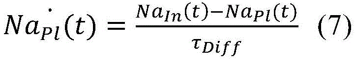
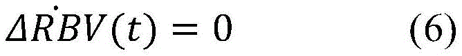
In a seventeenth aspect according to any of the preceding aspects, the controller (65) is configured to determine the blood property and/or the auxiliary blood parameter using a state space mathematical model, wherein the state space mathematical model comprises the following equations:

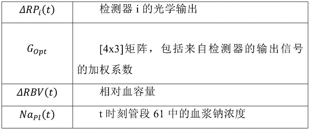
wherein,

in an eighteenth aspect according to the preceding aspects, the diffusion time (τ)Diff) Equal to:
wherein,
| VB(t) | absolute blood volume at time t |
| KDiff | Semipermeable membrane diffusion coefficient of sodium |
In a nineteenth aspect according to any one of the preceding two aspects, the dispersion time (τ)Diff) Approximately constant time, comprised between for example 1000 seconds and 1200 seconds.
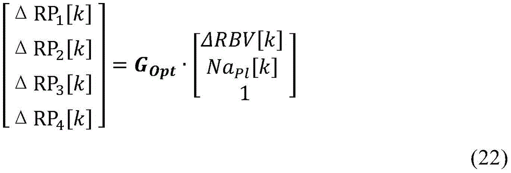
In a twentieth aspect according to any of the preceding aspects, the controller (65) is configured to determine both the blood property and the auxiliary blood parameter based on the output signals from the plurality of detectors (57) using a mathematical equation that linearly combines values of the blood property, the auxiliary blood parameter and the output signals.
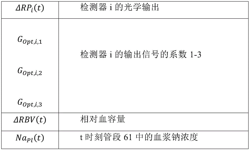
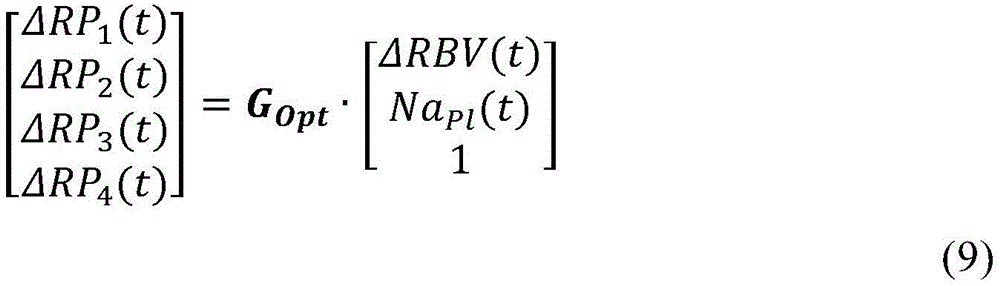
In a twenty-first aspect according to any one of the preceding aspects, the controller (65) is configured to determine both the blood property and the auxiliary blood parameter based on output signals from the plurality of detectors (57) using the following mathematical equations:
ΔRPi(t)=GOpt,i,1·ΔRBV(t)+GOpt,i,2·NaPl(t)+GOpt,i,3 (8)
wherein,
in a twenty-second aspect according to any of the preceding aspects, the controller (65) is configured to determine the blood property and/or the auxiliary blood parameter using a state space mathematical model, wherein in a bypass condition of the extracorporeal blood treatment apparatus in which the inlet dialysate does not enter the filtration unit but bypasses the filtration unit, the state space mathematical model comprises the following equations:

wherein,


in a twenty-third aspect according to any of the preceding aspects, the controller (65) is configured to further based on the outlet dialysate conductivity (σ)out) Determining auxiliary blood parameters, the conductivity of the outlet dialysateRate (sigma)out) Modeled as inlet dialysate conductivity (σ)in) And plasma conductivity (σ)pl) In particular a weighted average, wherein the outlet dialysate conductivity (σ) is determined by the average, in particular the weighted average, ofout) Is the conductivity of the dialysate flowing in the spent dialysate line (13) of an extracorporeal blood treatment apparatus, the inlet dialysate conductivity (σ)in) Is the conductivity of the dialysate flowing in the preparation line (19) of an extracorporeal blood treatment apparatus, the plasma conductivity (σ)pl) Is the electrical conductivity of the blood flowing in the tube section (61).
In a twenty-fourth aspect according to any of the preceding aspects, the controller (65) is configured to determine the secondary blood parameter also based on the following mathematical relationship:
σOut(t)=GMix·σPl(t)+(1-GMix)·σIn(t-τDelay) (11)
wherein,
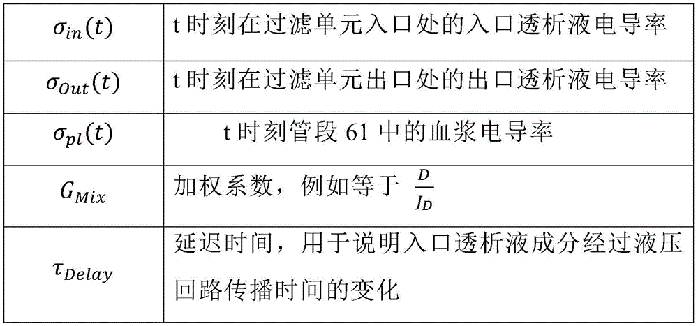
in a twenty-fifth aspect according to the preceding aspect, the weighting factor (G)Mix) Is proportional and in particular equal to:
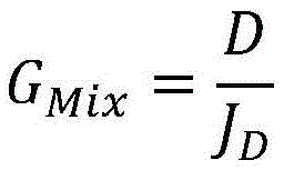
wherein,
| D | treatment Unit dialysis Rate |
| JD | Flow rate of dialysate |
In a twenty-sixth aspect according to any of the preceding two aspects, the weighting factor (G)Mix) Is constant, for example comprised between 0.4 and 0.6.
In a twenty-seventh aspect according to any of the preceding three aspects, a delay time (τ) to account for variations in the transit time of the inlet dialysate constituent through the hydraulic circuitDelay) Is constant, for example comprised between 100 and 200 seconds.
In a twenty-eighth aspect according to any one of the preceding aspects, the controller (65) is configured to further based on the plasma conductivity (σ)pl) To determine an auxiliary blood parameter, the plasma conductivity being the conductivity of the blood flowing in the tube section (61).
In a twenty-ninth aspect according to any one of the preceding aspects, the controller (65) is configured to determine the secondary blood parameter also based on the following mathematical relationship:
σPl(t)=GNa,Ga·NaPl(t)+GNa,Offset (12)
wherein,
| σpl(t) | plasma conductivity in |
| GNa,Gain | Constant coefficient |
| GNa,Offset | Constant coefficient |
| NaPl(t) | Plasma sodium concentration in |
In a thirtieth aspect according to any one of the preceding aspects, the controller (65) is configured to determine the blood property and/or the auxiliary blood parameter using a kalman filter.
In a thirty-first aspect according to any one of the preceding aspects, the controller (65) is configured to determine the blood property and/or the auxiliary blood parameter using a kalman filter comprising a prediction step based on the following equation:


wherein,
equations (14) and (15) are given as a function of the universal time step k (e.g., 1 second);
ukis [2x1]Including the sodium concentration (Na) of the inlet dialysate at the inlet of the filtration unit at time step kIn[k]) And time step k inlet dialysate conductivity (σ)In[k]);
xk -And xk +Is [2x1]Respectively, containing an auxiliary blood parameter (in particular the plasma sodium concentration (Na)Pl[k]) And blood properties (i.e., relative blood volume change at time step k (Δ RBV [ k ]))]) Predicted and corrected values of plasma sodium concentration and relative blood volume changes are state variables; x is the number ofk -Is the predicted system state at step k, and is xk-1 +And ukA function of (a);
q is a matrix of [2x2] that describes the process noise covariance.
A is a function f (·,) with respect to the relative blood volume change (Δ RBV) and plasma sodium concentration (Na)pl) Of [2x2]The Jacobian (Jacobian) matrix is linearized.
Pk -And Pk +Is the predicted and corrected [2x2] calculated at each step k according to equations (15) and (18), respectively]A covariance matrix is estimated.
In a thirty-second aspect according to the preceding aspect, the initial vector x0 +Is set to zero blood volume change, i.e., Δ RBV 0, and the plasma sodium concentration is equal to the subject's mean plasma sodium concentration, e.g., Napl=140mM。
In a thirty-third aspect according to any of the preceding two aspects, the initial diagonal matrix P+Is set to zero blood volume change, i.e., Δ RBV ═ 0, and plasma sodium concentration (Na)pl) Equal to a value less than 6mM, preferably equal to 4 mM.
In aspect 34 according to any of the preceding three aspects, the function f (·,) is defined by a discretized version of the equation according to aspect 17 in processing mode.
In a thirty-fifth aspect according to the preceding four aspects, the function f (·,) is defined by a discretized version of the equation according to aspect 22 in bypass mode.
In a thirty-sixth aspect according to any of the preceding aspects, the discretized version of the equation according to aspect 17 in the processing mode is as follows:
ΔRBV[k]=ΔRBV[k-1] (19)
wherein a forward euler discretization method is used.
In a thirty-seventh aspect according to any one of the preceding aspects 31 to 35, the kalman filter comprises a measurement-based correction step based on the following equation:


wherein
EkIs [2x 5] calculated according to equation (16)]The error gain matrix of (2);
r is a covariance diagonal matrix of [5x5], particularly the diagonal value of R associated with optical measurements is determined
Set equal to the root mean square fit residual of equation (9):
wherein
Dialysis conductivity (σ) with outletOut) The diagonal value of the associated R is the deviation between the dialysate (D) and the average (e.g., 250 ml/min);
Zkis the measured output 5x1]Is output by the signal (Δ RP)1[k]To Δ RP4[k]) And outlet conductivity (σ)Out[k]) Composition is carried out;
g(xk -,uk) Is the predicted output [5x1 ] calculated from the state output function g (·,)]The column vector of (2). The function g (·, ·) is determined by the time discrete equations (22), (23) and (24), given below:
σOut[k]=GMix·σPl[k]+(1-GMix)·σIn[k-kDelay] (23)
σPl[k]=GNa,Gain·NaPl[k]+GNa,Offset (24)
wherein


H is a function g (·,) with respect to the relative blood volume change (. DELTA.RBV) and the plasma sodium concentration (Na)pl) Of [5x2]The jacobian linearization matrix.
In a thirty-eighth aspect, a non-invasive sensor (50), in particular a blood volume sensor, for determining at least one blood property parameter and/or at least one auxiliary blood parameter of blood flowing in an extracorporeal section (61) (e.g. a tube section) of an extracorporeal blood treatment apparatus is provided, comprising:
-at least one source (53) for directing a signal along an emission axis (54) towards the blood;
-a plurality of detectors (57) for receiving the signals emitted by the source (53) after they have at least partially passed through the blood flowing in the section (61) and emitting respective output signals related to the received signals.
In a thirty-ninth aspect according to any of the preceding aspects, at least one detector, in particular all detectors, comprises a photodiode receiver.
In a fortieth aspect according to any of the preceding aspects, the source comprises a source of electromagnetic radiation or ultrasound.
In a forty-first aspect according to any one of the preceding aspects, the source comprises a light source, in particular an LED source.
In a forty-second aspect according to any one of the preceding aspects, the source comprises a multi-wavelength LED emitter comprising a plurality of LEDs (e.g., 5 LEDs) on the same chip, the pickup wavelengths being in the red and infrared bands.
In a forty-third aspect according to any one of the preceding aspects, the illumination peak wavelength of the source is comprised between 790 and 820nm, in particular between 800 and 810 nm.
In a fourteenth aspect according to any of the preceding aspects, the source comprises an optical fiber having one end coupled with the signal emitter and another end positioned to direct the emitted signal along the emission axis towards the blood.
In a forty-fifth aspect according to any one of the preceding aspects, the detectors are positioned at different angles relative to an emission axis.
In a sixteenth aspect according to any of the preceding aspects, the detector receives the same signal emitted by the source substantially simultaneously after the signal emitted by the source is transmitted and/or reflected and/or scattered by the blood flowing in the tubing segment.
In a forty-seventh aspect according to any one of the preceding aspects, the detectors collect reflected, scattered and/or transmitted signals according to their respective positions.
In a forty-eighth aspect according to any one of the preceding aspects, the detectors collect electromagnetic radiation, scattered electromagnetic radiation and/or transmitted electromagnetic radiation according to their respective positions.
In a forty-ninth aspect according to any one of the preceding aspects, at least one detector is positioned at about 180 degrees relative to the emission axis of the source and/or at least another detector is positioned at about 45 degrees relative to the emission axis of the source.
In a fifty-fifth aspect according to any of the preceding aspects, at least one detector is positioned at about 90 degrees relative to an emission axis of the source and/or at least another detector is positioned at about 0 degrees relative to the emission axis of the source.
In a fifty-first aspect according to any of the preceding aspects, the sensor comprises four different detectors for receiving electromagnetic radiation from the source, a first detector positioned at about 180 degrees relative to an emission axis of the source, a second detector positioned at about 90 degrees relative to the emission axis of the source, a third detector positioned at about 45 degrees relative to the emission axis of the source, and a fourth detector positioned at about 0 degrees relative to the emission axis of the source.
In a fifty-second aspect according to any of the preceding aspects, the detector is configured to receive a signal emitted by the source radially along a normal section of the blood flow in the tube of the extracorporeal blood treatment apparatus.
In a fifty-third aspect according to any of the preceding aspects, the sensor further comprises a housing, a portion of which substantially shape-matches a tube of the extracorporeal blood treatment apparatus, each detector comprising a respective end placed at the shape-matching portion, which faces the tube in the coupled condition of the housing and the tube, in particular the signal emitter comprising a respective end placed at the shape-matching portion, which faces the tube in the coupled condition of the housing and the tube.
In a fifty-fourth aspect according to any of the preceding aspects, the sensor further comprises a housing made of two or more components defining a through-channel, the housing being configured to be coupled to a tube of an extracorporeal blood treatment apparatus, in particular to completely house the tube segment within the through-channel.
In a fifty-fifth aspect according to the preceding aspect, the through-channel matches the outer shape of the tube segment of the extracorporeal blood treatment apparatus to which blood is to flow.
In a sixteenth aspect according to any of the preceding three aspects, the housing is configured to be tightly coupled with the outer surface of the pipe section.
In a fifty-seventh aspect according to any one of the preceding four aspects, the source comprises an optical fiber having one end coupled with the signal emitter and the other end fixed to a housing, a portion of which is form-matched with a tube of the extracorporeal blood treatment apparatus, the other end of the optical fiber being placed at the form-matched portion and facing the tube in a coupled state of the housing and the tube.
In a fifty-eighth aspect according to any one of the preceding aspects, at least one detector, in particular all detectors, comprises an optical fiber placed with one end in correspondence of the tube and with the other end coupled to a receiver (in detail, a photodiode receiver).
In a fifty-ninth aspect according to the preceding aspect, an end portion of the optical fiber corresponding to the tube is fixed to a housing, a portion of which is substantially shape-matched with the tube of the extracorporeal blood treatment apparatus, the end portion of the optical fiber being placed at the shape-matched portion and facing the tube in a coupled state of the housing and the tube section.
In a sixteenth aspect according to any of the two preceding aspects, the sensor comprises a printed circuit board with circuitry for transimpedance amplification, wherein the detector comprises a respective photodiode receiver connected to the printed circuit board, the circuitry for transimpedance amplification being a current-to-voltage converter and amplifying a current output of the detector.
In a sixteenth aspect according to the previous aspect, the printed circuit board comprises a low pass filter for filtering the signal leaving the circuit for transimpedance amplification, in particular the low pass filter having a cut-off frequency of about 30 Hz.
In a sixty-second aspect according to any one of the two preceding aspects, the sensor comprises a shielding case for preventing electromagnetic interference, the shielding case enclosing at least a printed circuit board with circuitry for transimpedance amplification and low-pass filtering.
In a sixteenth aspect, there is provided an apparatus for extracorporeal blood treatment, the apparatus comprising:
-the following stents (71, 7, 73) of the extracorporeal blood circuit (60) of this type: the extracorporeal blood circuit (60) comprising a treatment unit (2), an extraction line (6) connected to an inlet of the treatment unit (2) and a return line (7) connected to an outlet of the same treatment unit (2), the extracorporeal blood circuit (60) comprising an extracorporeal section (61), such as a tube section;
-a control unit (10) for driving an extracorporeal blood treatment apparatus; and
-at least one non-invasive sensor (50) according to any of the preceding aspects.
In a sixteenth aspect according to the previous aspect, the controller (65) of the non-invasive sensor (50) is part of the control unit (10).
In a sixty-fifth aspect according to the preceding aspect 63, the controller (65) of the non-invasive sensor (50) is separate from the control unit (10).
In a sixteenth aspect according to any of the preceding apparatus aspects, the apparatus comprises an extracorporeal blood circuit (60) mounted on the holder (71, 72, 73) and the tube section (61) is received by the sensor (50), wherein the tube section (61) is a tubular section (61) of a blood withdrawal or return line, and wherein the sensor (50) is configured to surround and contact an outer surface of the section (61) of the extracorporeal blood circuit when the sensor is in an operative state.
In a sixty-seventh aspect according to any one of the preceding apparatus aspects, the housing (51) of the sensor (50) includes:
-a first housing part (51a) with a respective detector end, and
-a second housing part (51 b);
wherein the first housing part (51a) and the second housing part (51b) are relatively movable between a loaded state of the sensor (50), in which the housing (51) is in an open state and the tube section (61) can be inserted into the housing, and an operating state of the sensor (50), in which the housing forms a longitudinal seat matching the shape of the outer surface of the tube section (61), and
wherein, in correspondence with said operating condition, the end of the detector faces, in particular contacts, a tube segment (61), which tube segment (61) is directed radially towards the tube segment development axis;
optionally, wherein the first housing portion (51a) is pivotably coupled to the second housing portion (51 b).
In a sixth configured sixty-eight aspect according to any of the preceding apparatus aspects, the apparatus comprises:
-an extracorporeal circuit (60) having the treatment unit (2) of the type wherein the treatment unit (2) has a semi-permeable membrane (5) separating the auxiliary chamber (4) from the main chamber of the same treatment unit (2);
-a preparation line (19) one end of which is configured to be connected to an inlet of an auxiliary chamber (4) of the processing unit (2);
-a spent dialysate line (13) one end of which is configured to be connected to an outlet of the auxiliary chamber (4);
wherein the control unit (10) is configured to command the execution of the following steps:
causing the patient's blood to flow in an extracorporeal blood circuit at a blood flow rate (Q)b) The flow of the mixture is controlled by the flow controller,
fresh treatment liquid is made to flow in the preparation line (19) at a flow rate (Qd)in) A flow direction to the auxiliary chamber (4);
the flow rate (Qd) of the used treatment fluid in the spent dialysate line (13)out) Flowing;
the conductivity (σ) of the substance receiving fresh treatment liquid flowing in the preparation line (19)in) Or concentration (Na)in) The associated one or more values;
receiving and processing the conductivity (σ) of the substance in the used process fluid flowing in the spent dialysate line (13)out) Or with the concentration (Na)out) The associated one or more measurements;
calculating at least one parameter value (D, K.t) indicative of the effectiveness of the extracorporeal blood treatment, according to:
the conductivity (σ) with the substance in the used treatment liquidout) Or concentration (Na)out) The one or more measured values of correlation
Conductivity (σ) of said substance of fresh treatment liquidin) Or concentration (Na)in) The associated one or more values;
flow ofThe conductivity (σ) of said substance in the blood passing through said section (61) of the extracorporeal blood circuitpl) Or concentration (Na)pl) The calculated value of (a);
at least one of the following: said flow rate (Qd) of fresh treatment liquidin) And said flow rate (Qd) of used process liquidout)。
In a sixty-ninth aspect according to any of the preceding apparatus aspects, the apparatus comprises:
-an extracorporeal circuit (60) with the treatment unit (2) of the type wherein the treatment unit (2) has a semi-permeable membrane (5) separating the auxiliary chamber (4) from the main chamber of the same treatment unit (2);
-a preparation line (19) one end of which is configured to be connected to an inlet of an auxiliary chamber (4) of the processing unit (2);
-a spent dialysate line (13) one end of which is configured to be connected to an outlet of the auxiliary chamber (4);
wherein the apparatus comprises at least two of said non-invasive sensors (50) such that a first tube section (61) of the blood withdrawal line is received by a housing (51) of a first of said two sensors (50) and a second tube section (61) of the blood return line is received by a housing (51) of a second of said two sensors,
and wherein the control unit is connected to each sensor (50) and is configured to:
causing the patient's blood to flow in an extracorporeal blood circuit at a blood flow rate (Q)b) The flow of the mixture is controlled by the flow controller,
fresh treatment liquid is made to flow in the preparation line (19) at a flow rate (Qd)in) Towards the auxiliary chamber (4);
the flow rate (Qd) of the used treatment fluid in the spent dialysate line (13)out) Flowing;
the conductivity (σ) of the substance receiving fresh treatment liquid flowing in the preparation line (19)in) Or concentration (Na)in) The associated one or more values;
bringing the patient's blood into extracorporeal blood circulation at a blood flow rate (Qb),
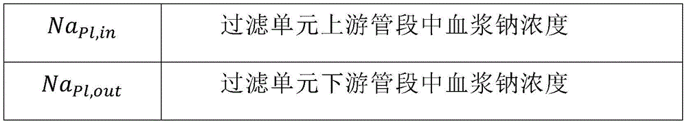
receive or calculate atThe conductivity (σ) of the substance in the blood flowing in the first section (61)pl,in) Or concentration (Na)pl,in) And the electrical conductivity (σ) of said substance in the blood flowing in said second segment (61)pl,out) Or concentration (Na)pl,out) The value of (a) is,
calculating at least one parameter value (D, K.t) indicative of the effectiveness of the extracorporeal blood treatment, according to:
conductivity (σ) of said substance of fresh treatment liquidin) Or concentration (Na)in) The one or more values of (a);
the conductivity (σ) of said substance in the blood flowing in said first section (61)pl,in) Or concentration (Na)pl,in) And the electrical conductivity (σ) of the substance in the blood flowing within the second segment (61)pl,out) Or concentration (Na)pl,out) Is determined by the value of (a) in (b),
the blood flow rate (Q)b)。
In a seventeenth aspect according to any one of the preceding two aspects,
the step of flowing fresh treatment liquid in the preparation line (19) comprises the sub-steps of: maintaining the concentration (Na) of the substance in the fresh treatment solutionin) Or electrical conductivity (σ)in) Is constant at a set value for at least a duration interval (T) during which a measurement of the conductivity or concentration for the purpose of said calculation of at least one value of a parameter (D, K.t) indicative of the effectiveness of the extracorporeal blood treatment is carried out, and
wherein, at least during the time interval (T), the control unit is configured to keep constant: the flow rate (Qd) of fresh treatment liquid in the preparation line (19)in) The flow rate of the patient's blood in the extracorporeal blood circuit (Qb), and the flow rate of the ultrafiltration flow through the semipermeable membrane (Q)F)。
In a seventeenth aspect according to any of the preceding three aspects, the parameter (D, K · t) indicative of the effectiveness of the extracorporeal blood treatment is the dialysis rate (D) of the substance calculated using one of the following formulae:
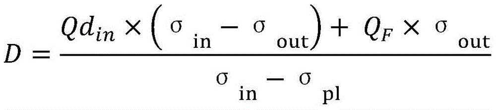
or
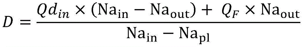
Or

Or
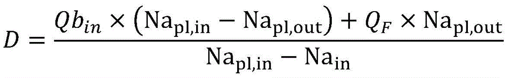
Wherein,

in a seventy-second aspect according to any one of the preceding apparatus aspects, the apparatus comprises an in-line fluid preparation portion (100) connectable to the extracorporeal blood circuit (60) and configured to prepare a priming solution.
In a seventy-third aspect according to any one of the preceding apparatus aspects, the apparatus comprises the processing unit (2), wherein:
-one end of the preparation line (19) is connected to the inlet of the auxiliary chamber (4) of the treatment unit (2),
-one end of a spent dialysate line (13) is connected to an outlet of the auxiliary chamber (4),
-a blood withdrawal line (6) is connected at the inlet of the main chamber (3), and
-a blood return line (7) is connected at the outlet of the main chamber (3).
In a seventeenth aspect, a process for determining at least one blood property and/or blood auxiliary parameter of blood flowing in an extracorporeal section (61) (e.g. a tube section) of an extracorporeal blood treatment apparatus is provided, wherein a non-invasive sensor (50), in particular a blood volume sensor, comprises:
-at least one source (53) for directing a signal along an emission axis (54) towards the blood.
-a plurality of detectors (57) for receiving the signals emitted by the source (53) after they have at least partially passed through the blood flowing in the segment (61) and emitting respective output signals related to the received signals,
the process comprises the following steps:
receiving respective output signals from a plurality of detectors (57); and
determining a value of the blood property from the output signal,
in particular, wherein the blood property comprises a blood volume change or a hemoglobin concentration or a parameter directly related to a blood volume change or a hemoglobin concentration.
In a 75 th aspect according to the preceding aspect, the process comprises determining a value of an auxiliary blood parameter, the auxiliary parameter being plasma conductivity (σ)Pl) A parameter related to the plasma conductivity, the concentration (Na) of at least one substance (e.g. sodium) in the bloodpl) And a concentration related parameter of at least one substance in the blood.
In a seventeenth aspect according to any of the preceding procedural aspects, the procedure comprises determining values of blood properties based on output signals from a plurality of detectors (57).
In a seventy-seventh aspect according to any of the preceding procedural aspects, the procedure comprises determining a temporal variation of the auxiliary blood parameter based on the output signal.
In a seventy-eighth aspect according to any of the preceding procedural aspects, the procedure comprises determining a temporal change in a property of the blood based on the output signal.
In a seventy-ninth aspect according to any of the preceding process aspects, the process comprises: receiving the sodium concentration (Na) of the inlet dialysate flowing in the preparation line (19) of the extracorporeal blood treatment apparatus (1)in) And based on the inlet dialysate sodium concentration (Na)in) Determining a value of the auxiliary blood parameter.
In an eighty-first aspect according to any of the preceding process aspects, the process comprises: receiving the sodium concentration (Na) of the inlet dialysate flowing in the preparation line (19) of the extracorporeal blood treatment apparatus (1)in) And based on the inlet dialysate sodium concentration (Na)in) Determining a value of the blood property.
In an eighty-first aspect according to any of the preceding process aspects, the process comprises: receiving the conductivity (σ) of the inlet dialysate flowing in the preparation line (19) of the extracorporeal blood treatment apparatus (1)in) And based on the inlet dialysate conductivity (σ)in) Determining a value of the auxiliary blood parameter.
In an eighty-second aspect according to any of the preceding process aspects, the process comprises: receiving the conductivity (σ) of the inlet dialysate flowing in the preparation line (19) of the extracorporeal blood treatment apparatus (1)in) And based on the inlet dialysate conductivity (σ)in) Determining a value of the blood property.
In an eighty-third aspect according to any of the preceding process aspects, the process comprises: receiving the conductivity (σ) of the outlet dialysate flowing in the spent dialysate line (13) of the extracorporeal blood treatment apparatus (1)out) And based on the outlet dialysate conductivity (σ)out) Determining a value of the auxiliary blood parameter.
In an eighty-fourth aspect according to any of the preceding process aspects, the process comprises: receiving the conductivity (σ) of the outlet dialysate flowing in the spent dialysate line (13) of the extracorporeal blood treatment apparatus (1)out) And based on the outlet dialysate conductivity (σ)out) Determining theA value of a blood property.
In an eighty-fifth aspect according to any of the preceding process aspects, the process comprises:

wherein,

in an eightieth aspect according to any of the preceding process aspects, the process comprises: both the blood property and the auxiliary blood parameter are determined based on output signals from the plurality of detectors (57) using a mathematical equation that linearly combines values of the blood property, the auxiliary blood parameter and the output signals.
In an 87 th aspect according to any of the preceding process aspects, the process comprises determining both the blood property and the auxiliary blood parameter based on output signals from a plurality of detectors (57) using the following mathematical equations:
ΔRPi(t)=GOpt,i,1·ΔRBV(t)+GOpt,i,2·NaPl(t)+GOpt,i,3 (8)
wherein,

in an eighteenth aspect according to any of the preceding process aspects, the process comprises determining the blood property and/or the auxiliary blood parameter using a state space mathematical model, wherein the state space mathematical model comprises the following equations in a bypass condition in an extracorporeal blood treatment apparatus in which the inlet dialysate is not directed into the filtration unit but instead bypasses the filtration unit:

wherein,

in an eighty-ninth aspect according to any of the preceding process aspects, the process comprises: also based on outlet dialysate conductivity (σ)out) Determining an auxiliary blood parameter, the outlet dialysate conductivity (σ)out) Modeled as inlet dialysate conductivity (σ)in) And plasma conductivity (σ)pl) In particular a weighted average, wherein the outlet dialysate conductivity (σ) is determined by the average, in particular the weighted average, ofout) Is the conductivity of the dialysate flowing in the spent dialysate line (13) of an extracorporeal blood treatment apparatus, the inlet dialysate conductivity (σ)in) Is the conductivity of the dialysate flowing in the preparation line (19) of an extracorporeal blood treatment apparatus, the plasma conductivity (σ)pl) Is the electrical conductivity of the blood flowing in the tube section (61).
In a nineteenth aspect according to any of the preceding process aspects, the process includes determining the auxiliary blood parameter further based on the following mathematical relationship:
σOut(t)=GMix·σPl(t)+(1-GMix)·σIn(t-τDelay) (11)
wherein,
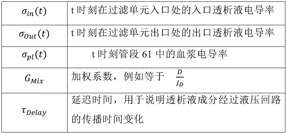
in a nineteenth aspect according to any of the preceding process aspects, the process includes further basing the process on plasma conductivity (σ)pl) To determine an auxiliary blood parameter, the plasma conductivity being the conductivity of the blood flowing in the tube section (61).
In a 92 th aspect according to any of the preceding process aspects, the process comprises determining the auxiliary blood parameter further based on the following mathematical relationship:
σPl(t)=GNa,Gain·NaPl(t)+GNa,Offset (12)
wherein,
| σpl(t) | plasma conductivity in |
| GNa,Gain | Constant coefficient |
| GNa,Offset | Constant coefficient |
| NaPl(t) | Plasma sodium concentration in |
In a nineteenth aspect according to any of the preceding process aspects, the process comprises determining the blood property and/or the auxiliary blood parameter using a kalman filter.
Glossary
In all the equations provided in the following description of the detailed operation of the extracorporeal blood treatment apparatus, the following terms are always used.

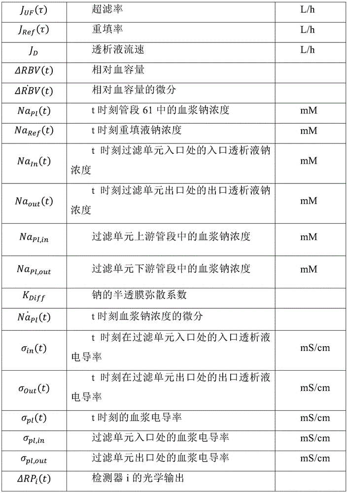

Drawings
Aspects of the invention are illustrated in the accompanying drawings, which are provided by way of non-limiting example, and in which:
fig. 1 shows a schematic view of a blood treatment apparatus according to an aspect of the present invention;
fig. 2 shows a schematic view of an alternative embodiment of a blood treatment apparatus according to another aspect of the present invention;
FIG. 3 is a schematic diagram of a measurement system according to one embodiment of the invention;
FIG. 3a shows a schematic perspective view of a housing for receiving a tube segment having blood flowing therein;
FIG. 3b is another aspect of a measurement system for revealing certain components of the circuit;
FIG. 4 is a schematic illustration of an experimental set-up;
FIG. 5 shows the dialysate Na entering the upstream side of the filtration unitInThe sodium step protocol of (1); the dashed line shows the dual protocol with the inversion step, the large black dot indicating the blood gas sampling time;
FIG. 6 is a schematic diagram of a hemodialysis machine having blood and dialysate inlet/outlet ports with a conductivity cell measuring inlet dialysate conductivity (σ)In) And outlet dialysate conductivity (σ)Out) (ii) a The black dashed line represents the bypass state;
FIG. 7 is a schematic diagram of a blood pool model for calculating a reference signal;
FIG. 8 shows the relationship between input signals, state variables and output signals, with dashed lines indicating unreliable connections in bypass mode;
FIG. 9 illustrates transitions between different filter versions for bypass state management;
10a to 10f show examples of state estimation results, where FIGS. 10a, 10b and 10c show Δ RBV estimation for three different experimental procedures, and FIGS. 10d, 10e and 10f show Na for the corresponding experimentsPlEstimating; the black dashed line shows the reference data, the light grey solid line shows the kalman-based state variable estimation, the black dashed line shows the estimation confidence interval, and the dark grey solid line shows the interval of estimation performed in bypass mode.
FIG. 11 shows a schematic front view of a cabinet structure of the apparatus of FIG. 1 or FIG. 2;
FIG. 12 shows the light intensity measured at a number of angles, normalized to the value at the start of the treatment;
figure 13 shows the light intensity measured at a normalized 45 ° channel; the signal has been subjected to a trend processing (de-tend procedure) to eliminate slow drift due to the RBV effect; and
fig. 14 is a flow chart showing the main steps of a process of determining attributes and auxiliary parameters of extracorporeal blood.
Detailed Description
In figures 1 and 2, a non-limiting embodiment of a device 1 for extracorporeal treatment of blood is shown, which can implement the innovative aspects of the present invention. In the following description and in fig. 1 and 2, like reference numerals refer to like components.
The device 1 comprises at least one sensor 50 for determining the value of one or more blood or plasma parameters.
Fig. 1 shows an apparatus 1 configured to implement any one of processes such as ultrafiltration, hemodialysis and hemodiafiltration, while fig. 2 shows an apparatus configured to implement a hemodialysis or ultrafiltration process.
The apparatus 1 comprises: a treatment unit 2 (e.g. hemofilter, ultrafilter, hemodialysis filter, dialyzer, plasmafilter, etc.) having a main chamber 3 and an auxiliary chamber 4 separated by a semi-permeable membrane 5. The membrane 5 of the processing unit 2 may be selected to have different properties and properties depending on the process.
A blood withdrawal line 6 is connected to the inlet of the main chamber 3 and a blood return line 7 is connected to the outlet of the main chamber 3. The blood withdrawal line 6, the main chamber 3 and the blood return line 7 are part of an extracorporeal blood circuit, which is identified in its entirety by reference numeral 60 in fig. 1 and 2. In use, the blood withdrawal line 6 and the blood return line 7 are connected to a needle or catheter or other access device (not shown) which is then placed in fluid communication with the vascular system of the patient so that blood may be withdrawn through the blood withdrawal line, through the primary chamber and then back to the vascular system of the patient through the blood return line. An air separator (e.g. a bubble trap 8) may be present on the blood return line. The extracorporeal blood circuit is supported by one or more racks provided in a conventional manner by a support frame 70 of the apparatus 1. For example, as shown in fig. 11, extracorporeal blood circuit 60 may be supported by a support 71, a support 72 and a support 73, support 71 supporting the bubble trap, support 72 supporting treatment unit 2, support 73 being positioned in correspondence with the blood pump.
A safety clip 9 controlled by the control unit 10 may be present on the blood return line downstream of the bubble trap 8. There may be a bubble sensor 8a, for example associated with the bubble trap 8 or coupled to a portion of the line 7 between the bubble trap 8 and the clamp 9. If a bubble sensor is present, the bubble sensor is connected to the control unit 10 and, in case one or more bubbles exceeding a certain safety threshold are detected, sends a signal of the control unit to cause the gripper 9 to close. The flow of blood through the blood line may be controlled by a blood pump 11 (e.g., a peristaltic blood pump), which blood pump 11 acts on the blood withdrawal line (as shown in fig. 1) or on the blood return line. The operator can input the set value of the blood flow rate Qb: during the treatment, the control unit 10 is configured to control the blood pump based on the set blood flow rate. Note that the control unit 10 may also be connected to a user interface 12 (e.g. a graphical user interface), which user interface 12 receives operator inputs (e.g. in particular blood flow rate set values) and displays device outputs. For example, graphical user interface 12 may include a touch screen for displaying output and allowing user input, or a display screen and hard keys for inputting user input, or a combination thereof.
A waste dialysate line 13 configured to drain waste water from the auxiliary chamber 4 is connected at one end to an outlet of the auxiliary chamber 4 and at the other end to waste, which may be a drain or a waste water container 14 (dashed lines in fig. 1 and 2) for collecting liquid extracted from the auxiliary chamber. The sewage pump 17 is operated on the spent dialysate line 13 under the control of the control unit 10 to adjust the flow rate Qd of sewage through the spent dialysate lineout. The net ultrafiltration (i.e. the net fluid removed from the blood by the semipermeable membrane of the treatment unit 2) can be determined by the flow rate difference between the dialysate pump 21 and the waste water pump 17 on the fresh dialysate line 19. Alternatively (or in combination), the apparatus may further comprise an ultrafiltration line 25, which ultrafiltration line 25 branches off from the spent dialysate line 13 and is provided with a corresponding ultrafiltration pump 27, which ultrafiltration pump 27 is also controlled by the control unit 10 to cause a flow rate Q along the ultrafiltration lineF. The embodiment of fig. 1 presents a pre-dilution fluid line 15 connected to a blood withdrawal line. The line 15 supplies displacement fluid from an infusate container 16, the infusate container 16 being connected at one end to the pre-dilution fluid line. Although fig. 1 shows the container 16 as a source of infusion liquid, this should not be construed in a limiting manner: in practice, the infusate may also come from an in-line preparation section. Note that in addition to the pre-dilution fluid line, the apparatus of fig. 1 may include a post-dilution fluid line (not shown in fig. 1) that connects the in-line preparation of the infusate container or infusate solution to the blood return line. Finally, as a further alternative (not shown in fig. 1), the device of fig. 1 may comprise a pre-dilution fluid line and a post-infusion fluid line: in this case, it is preferable that the air conditioner,each infusate line may be connected to a respective infusate container or may receive infusate from the same source of infusate (e.g., the same infusion container or online preparation area). In the case of on-line preparation of the infusion fluid, the source of the infusion fluid may be an on-line preparation of the device 1 (i.e. the on-line preparation 100 as described below), or a different device similar to the portion 100 and connected to the infusion line and configured to supply fluid to the post-dilution and/or pre-dilution line. In addition, an infusion pump 18 operates on the infusion line 15 to regulate the flow rate Q through the infusion line 15rep1. Note that in the case of two infusion lines (pre-dilution and post-dilution), each infusion line may be provided with a respective infusion pump.
The apparatus of fig. 1 further comprises a fluid preparation line 19 connected at one end to the water inlet and at its other end to the inlet of the auxiliary chamber 4 of the filtration unit for supplying fresh treatment liquid to the auxiliary chamber 4. The dialysate pump 21 operates on the fluid preparation line under the control of the control unit 10 to supply fluid from a fresh treatment fluid source (e.g. a container or a portion 100 for on-line preparation of fresh dialysate) at a flow rate QdinTo the auxiliary chamber.
In the example of fig. 1 and 2, the line 19 links the hemodialysis machine or hemodialysis filter 2 to an online preparation 100 for preparing dialysate. The in-line preparation section 100 comprises a main line 101, the upstream end of which main line 101 is designed to be connected to a water source. The first auxiliary line 102 and the second auxiliary line 103 are connected to the main line 101, and are configured to supply at least a necessary amount of buffer and a necessary amount of electrolyte. The first auxiliary line 102, which may loop back onto the main line 101, is configured to fit a first container 104 (e.g., a bag or cartridge or other container) containing a buffer. Line 102 is also equipped with a first metering pump 105 for metering the buffer into the fresh process liquid: as shown in fig. 1, the pump may be located downstream of the first vessel 104. The operation of the pump 105 may be controlled by the control unit 10 based on a comparison between: 1) a set point value for the buffer concentration of the solution formed at the junction of the main line 101 and the first auxiliary line 102, and 2) a value for the mixed buffer concentration, measured by a first probe 106, the first probe 106 being located in the first auxiliary line downstream of the first container 104 or in the main line 101 immediately downstream of the junction between the main line 101 and the first auxiliary line 102. Furthermore, the free end of the second auxiliary line 103 is intended to receive a fluid from a second container 107, this second container 107 containing a concentrated salt solution, for example electrolytes, such as sodium chloride, calcium chloride, magnesium chloride and potassium chloride. In a variant, the second auxiliary line 103 can also loop back onto the main line 101. Furthermore, in case one wishes to feed separate electrolytes or electrolyte components from the respective containers, a plurality of separate second auxiliary lines 103 may be envisaged. Note that the second auxiliary line 103 is equipped with a second metering pump 108 for metering the electrolyte into the fresh treatment liquid; the operation of the second metering pump depends on a comparison between: 1) a conductivity setpoint or an electrolyte concentration setpoint of the solution formed at the junction of the main line 101 and the second auxiliary line 103, and 2) a value of the conductivity or the electrolyte concentration of the solution measured by a second probe 109, the second probe 109 being located in the second auxiliary line downstream of the second container 107 or in the main line 101 immediately downstream of the junction between the main line 101 and the auxiliary line 103. Note that the specific nature of the concentrate contained in the containers 104 and 107 may vary depending on the circumstances and the type of fresh treatment fluid to be prepared. Furthermore, the nature and location of the first and second probes may depend on the type of buffer used, the type of electrolyte concentrate employed, and the particular configuration of the circuit formed by the main and auxiliary lines. Furthermore, as already mentioned, in the case of the need to add a plurality of different types of substances to prepare a fresh treatment liquid, there may be more than two auxiliary lines with respective concentrate containers and respective metering pumps.
The second probe is typically a conductivity meter configured to measure the conductivity σ of the dialysate upstream of the filtration unit 2in. Of course, the dialysate conductivity σinSet by the operator or set and controlled by the apparatus during the treatment. Accordingly, the apparatus comprises a further conductivity meter 112, which isPlaced on the spent dialysate line 13 to sense the conductivity σ of the dialysate downstream of the filtration unit 2out. Both conductivity meters 109 and 112 provide respective measurement signals to the device control unit 10.
The embodiment of fig. 2 shows an alternative apparatus 1 designed for carrying out any one of the treatments such as hemodialysis and ultrafiltration. In the device shown in fig. 2, the same components described for the embodiment of fig. 1 are identified by the same reference numerals and are therefore not described again. In fact, unlike the hemodiafiltration device of fig. 1, the device of fig. 2 does not present any infusion lines.
In each of the above embodiments, a flow sensor 110, 111 (volume or mass type flow sensor) may be used to measure the flow rate in each line. The flow sensor is connected to the control unit 10. In the example of fig. 1, where the infusion line 15 and the ultrafiltration line 25 lead to containers or bags 16, 23, respectively, a scale may be used to detect the amount of fluid delivered or collected. For example, the apparatus of fig. 1 comprises: a first balance 33 for providing weight information W about the amount of fluid collected in the ultrafiltration vessel 231(ii) a And a second balance 34 for providing weight information W on the amount of fluid supplied from the infusion container 162. In the embodiment of fig. 2, the apparatus comprises: a first balance 33 for providing weight information W on the amount of fluid collected in the ultrafiltration vessel 231. The scales are all connected to a control unit 10 and the weight information W is transmittediA control unit is provided to determine the actual amount of fluid in each container and the actual flow rate of fluid supplied or received by each container.
In the example of fig. 1 and 2, in order to control the fluid balance between the amount of fluid supplied to the auxiliary chamber 4 and the amount of fluid extracted from the auxiliary chamber, flow sensors 110, 111 located on the fresh and spent dialysate lines 13 provide signals to the control unit 10 indicative of the flow of fluid through the respective lines, and the scales provide weight information that allows the control unit to derive the flow rates through the ultrafiltration line 25 and through the infusion line 15 (if present). The control unit is configured to control at least the pumps 17, 21 and 27 (and in the case of fig. 3 also the pump 18) to ensure that a predetermined patient fluid removal is achieved during a prescribed treatment time (as required by a prescription provided to the control unit via e.g. the user interface 12). Note that other fluid balancing systems may be used: for example, where the apparatus includes a reservoir for the fresh treatment fluid and a reservoir for collecting waste, a scale may be used to detect the amount of fluid delivered or collected by each reservoir and then notify the control unit accordingly. As a further alternative, a system based on volume control may be used, wherein the preparation line 19 and the spent dialysate line 13 are connected to an equilibrium chamber system to ensure that the amount of liquid flowing into line 19 at each moment in time is the same as the amount of liquid leaving from line 13.
From a structural point of view, one or more of the containers 104, 107, 16, 23 may be disposable plastic containers. The blood lines 6, 7 and the filter unit may also be disposable plastic components which can be installed at the beginning of the treatment session and then discarded at the end of the treatment session. Pumps, such as peristaltic or positive displacement pumps, have been described as a means of regulating the flow of fluid through each line. However, it should be noted that other flow regulating devices, such as valves or a combination of valves and pumps, may alternatively be employed. The balance may include a piezoelectric sensor, a strain gauge or a spring sensor, or any other type of transducer capable of sensing a force applied thereto.
Measuring system
According to an aspect of the invention, the apparatus 1 comprises at least one blood or plasma parameter sensor 50 configured to be positioned in correspondence with at least one segment 61 of the extracorporeal blood circuit 60.
The sensor 50 is a non-invasive sensor, i.e. it is not in contact with the blood flowing within the extracorporeal blood circuit 60, and in particular it is applied outside the section of the extracorporeal blood treatment apparatus. In the following, by non-limiting way, a segment of an extracorporeal blood treatment apparatus is meant a tubing segment. From a constructional point of view, the sensor 50 comprises a plastic housing 51, which is only schematically represented in the figures. The housing 51 is designed to be tightly coupled to a blood line section 61 of an extracorporeal blood circuit 60 where a blood or plasma parameter needs to be measured. The housing 51 may be a separate body or may be attached to or be part of the support frame 70 of the device 1. For example, fig. 11 schematically shows that the housing 51 is attached to the front panel of the support frame 70 and is configured to receive at least one (in the example of the figures, one) segment 61 of the extracorporeal blood circuit.
For this purpose, the housing 51 may be directly form-matched (counter-shaped) to a portion of the tube of the blood line, i.e. to a circular cross-sectional section of the flexible transparent plastic tube of the blood withdrawal line 6 or the blood return line 7. The housing may be an open and closed housing defining an internal through channel 52 intended to receive the tube of the blood circuit.
Notably, the housing 51 may be made of two or more parts 51a, 51b, which may be separate or joined (e.g., hinged) together to define a non-coupled configuration (see fig. 3a) and a coupled configuration (see fig. 3). In the coupled configuration, the through passage 52 matches the shape of the tube to be received, so as to perfectly couple with it and receive it.
The schematic shows the case where a flexible blood tube is coupled to sensor 50. However, the housing 51 may alternatively be shaped to mate with a rigid cuvette (e.g., for Ganbullona, Inc.)
 The cuvette of the sensor). In this case, the flexible tube of the blood circuit has a rigid cuvette suitably applied to allow the blood flowing in the
 extracorporeal blood circuit 60 to pass through the cuvette itself. In the latter case, the through-channel matches the shape of the outer surface of the cuvette, which is not necessarily circular, but alternatively the through-channel may have a flat outer surface (polygonal cross-section).
It is clear that in case of applying the housing to a circular flexible tube of the extracorporeal blood circuit 60, any position of the sensor along the blood withdrawal line 6 or the blood return line 7 is suitable. In the case where the sensor 50 has a through channel matching the shape of a particular cuvette, then the sensor should be applied in a position corresponding to the cuvette itself for proper operation.
The housing 51 may be made of a highly light-absorbing material that prevents external ambient light from reaching the receiver.
The signal source 53 may comprise any suitable signal emitter (e.g., an optical or acoustic emitter) that directs a suitable emitted signal to the interior of the tube in which the blood is flowing.
In an embodiment of the invention, the signal source 53 comprises a source of electromagnetic radiation, in particular a light source such as an organic Light Emitting Diode (LED) light source.
In the following description we refer to optical emitters and more particularly to LED emitters 55. However, this should not be construed as limiting.
The peak wavelength of the signal source is typically set at 800-810nm, corresponding to the point in the hemoglobin (Hgb) absorption spectrum where the absorption is independent of oxidation. Again, this should not be considered a limiting aspect.
A specific implementation of signal source 53 includes a multi-wavelength LED emitter for emitting light (i.e., MTMD6788594SMT6 manufactured by mark tex corporation, new york, usa). In particular, emitter 55 comprises 5 LEDs on the same chip, with peak wavelengths in the red/infrared band. Source 53 also includes an optical fiber 56, one end 56a of fiber 56 being coupled to signal emitter 55 and the other end 56b being fixed to housing 51 and positioned to direct the optical signal along emission axis 54 toward the blood. As shown in fig. 3, the second end 56b of the transmitter optical fiber 56 is placed at the shape matching portion and faces the tube in a state where the housing is coupled with the tube section 61.
The sensor 50 comprises a plurality of detectors 57 for receiving signals emitted by said source after at least partial passage through the blood, in particular the detectors 57 collect reflected signals, scattered signals and/or transmitted signals depending on their respective position. Since the emitter 55 is an LED emitter, the detector 57 comprises a photodiode receiver 58.
In advantageous embodiments, the light detectors 57 are placed at different angles with respect to the emission axis 54. In more detail, the sensor 50 of fig. 3 includes four different detectors 57 for receiving electromagnetic radiation from the signal source 53, wherein a first photodiode receiver PD1 is positioned at about 180 ° with respect to the emission axis 54 of the signal source, a second photodiode receiver PD2 is positioned at about 90 ° with respect to the emission axis of the signal source, a third photodiode receiver PD3 is positioned at about 45 ° with respect to the emission axis of the signal source, and a fourth photodiode receiver PD4 is positioned at about 0 ° with respect to the emission axis of the signal source. Of course, more (or less) than 4 receivers may be used, and more than one receiver may be placed at the same angle relative to the transmission axis 54, depending on particular needs.
Each detector 57 is configured to receive a signal emitted by the signal source and radial (substantially reflected, scattered or transmitted) to the normal section of the blood flow in the tube of the extracorporeal blood treatment apparatus. The new measurement system extends the architecture of conventional designs to collect light at different geometric angles relative to the emitter, allowing differentiation between reflected, scattered and transmitted light. If the scattered light is received by different receivers at the same time, the loss of transmitted light due to the increase in scattering is not erroneously detected as an increase in absorbance.
To achieve the above configuration, each detector 57 comprises a respective optical fiber 59, one end of which is placed in correspondence with a tube segment 61, and the other end of which is coupled to a receiver (in detail a photodiode receiver). In more detail, the end of the optical fiber 59 corresponding to the tube is fixed to the housing 51, and is placed at the shape matching portion and faces the tube in the coupled state of the housing and the tube section.
As described above, all channels for receiving signals are placed radially along the normal cross-section of the blood flow, except for the reflection channel (0 degrees), which is slightly offset in the flow direction to allow placement of the emitting fiber 56. The emitted light and the collected light are coupled to and from the ancestry using, for example, plastic optical fiber (ESKA GH4001 produced by mitsubishi yang).
The photodiode receiver 58 may have a particular fiber coupling mechanism (e.g., IFD91 manufactured by Industrial fiber company of Tanper, USA) for the light collection channel, corresponding to PD1-PD4 in FIG. 3.
The photodiode receiver 58 is housed on a printed circuit board 60 together with an analog circuit 62 for transimpedance amplification. The circuit 62 for transimpedance amplification includes a current-to-voltage converter (e.g., implemented using an operational amplifier). The circuit 62 may be used to amplify the current output of the photodiode receiver 58. Current-to-voltage converters are used with photodiodes whose current response is more linear than the voltage response (current responses typically have better than 1% linearity over a wide range of light inputs). The transimpedance amplifier provides a low impedance to the photodiode and isolates it from the output voltage of the operational amplifier. There are several different configurations of transimpedance amplifiers, one factor common to them is the need to convert the low level current of the sensor to a voltage.
The printed circuit board 60 further comprises a low pass filter stage 63 and a gain stage amplification. The cutoff frequency of the low-pass filter 63 is set to, for example, 30 hz. Based on preliminary testing and calibration, the gain is set to a channel-specific value. The analog signal is then converted to a digital signal by a suitable (ADC) converter 64. In more detail, the analog output was sampled at 100Hz using a NI USB-6008DAQ card (manufactured by Italian national instruments, Milan, Italy) with a 12-bit resolution and recorded by a custom LabView virtual instrument.
The multi-LED emitter, signal conditioning board and DAQ card are assembled together on a 3D printed housing and placed in a grounded metal box for electromagnetic shielding (see fig. 3) and provided with openings for optical fibers 56, 59, data connections and power supply.
As will be apparent from the detailed description below, the digital signals are input to the controller 65 for detecting one or more parameters of the blood flowing in the tubing segment 61 of the extracorporeal blood treatment apparatus.
Modeling and estimation
The general physical principle of using non-invasive sensors to determine relevant blood or plasma parameters is related to the fact that: changes in osmotic pressure change the shape of the red blood cells and thus their optical properties. Osmolarity is a measure of the concentration of a solute and is defined as the number of osmolality per liter of solute in a solution. As previously mentioned, sodium is the highest concentration solute in dialysate and plasma and is therefore the main driver of osmotic pressure.
Thus, the applicant has appreciated that the (e.g. light) response signal measured from the (e.g. light) detector during the estimation of the blood volume change is influenced by the concentration of red blood cells and the osmotic pressure (and thus mainly by the blood/plasma sodium content).
Furthermore, the applicant has also unexpectedly found that several detectors placed at different angles with respect to a tube segment of extracorporeal blood flow for combined Hematocrit (HCT)/blood volume change (Δ RBV) and Osmolarity (OSM)/sodium content (Na)pl) The changes have different responses. The basic principle is as follows: decoupling HCT and Na using one or more mathematical formulas based on data from a general N channels of the N detectorsplThe influence of (c). This method allows determining a plurality of blood parameters of interest without the need to sample the blood or to influence the treatment during the measurement; the relevant parameters may be selected as the relative blood volume change (Δ RBV) and the plasma sodium concentration according to, for example, the following relationship:
Δ RBV (t) ═ function1(I0(t),I1(t),I2(t),....,I_N(t));
Napl(t) function2(I0(t),I1(t),I2(t),....,I_N(t)).
Wherein I0 identifies the output signal from detector 0; i _ N identifies the output signal from detector N. Each detector has its own channel i (1 to N).
There are many possible formulation forms for the function. For example, a possible formula is a linear combination of channel values, which may be raised to a power factor, so that each channel more or less affects the corresponding parameter, depending on the effect of a particular blood property on the signal captured at a particular angular position.
ΔRBV(t)=K0*(I0(t))^a0+K1*(I1(t))^a1+,....,+K_N*(I_N(t))^aN;
Napl(t)=J0*(I0(t))^b0+J1*(I1(t))^b1+,....,+J_N*(I_N(t))^bN.
More complex classifiers or neural networks are another possibility. For example, a neural network may be trained such that it receives as inputs: the signals of the various detectors, and possibly other input variables related to blood volume changes and plasma sodium concentration, such as the conductivity in the dialysate circuit (upstream and downstream filtration units) and/or the sodium concentration in the fresh dialysate. The neural network provides as output the value of the desired blood parameter, thereby successfully decoupling the optical effect of the change in shape due to the osmotic pressure and the concentration of red blood cells.
It is obvious that a better estimate of the change in blood volume can be obtained if the effect of osmotic pressure can be detected and decoupled. At the same time, it is very important to note that it is also possible to derive the Na concentration in the plasmaplIs estimated.
In other words, since sodium content in blood or plasma has a major effect on osmotic pressure, determining and eliminating such effects allows for an appropriate estimation of blood volume changes during treatment; in addition, since the effects of plasma sodium concentration are decoupled, estimation of this parameter is also feasible.
The results show that some specific channels are most sensitive to specific parameters, while others behave more like a mixture of properties (hematocrit and osmolarity).
Fig. 12 shows the light intensity measured at different angles, which has been normalized to the value at the beginning of the process. There is a small section in the middle where the recording is interrupted to allow the settings to be modified. With respect to the previously described sensor implementation, the graph includes signals from additional photodetectors placed at 135 degrees. However, the general concepts described herein do not depend on the number and location of the various detectors.
Fig. 12 shows that the 0 ° channel (reflected light, red line) depends mainly on ultrafiltration and RBV variation.
Fig. 13 shows a normalized 45 ° channel (scattered light, blue line). The signal has been detrended to eliminate slow drift due to the RBV effect. This process is not suitable for real-time algorithms, but linear combination methods can be used to create real-time detrending. As shown, the detrended 45 ° channel is capable of detecting changes in osmotic pressure caused by changes in dialysate sodium concentration. The first order response is primarily due to the time required to adjust the blood sodium concentration to the dialysate sodium value.
In other words, the various signals detected at different angular positions are affected differently by plasma sodium and relative blood volume changes. Thus, by appropriate signal manipulation, the two blood parameters mentioned can be determined more accurately in real time and non-invasively.
For establishing a blood parameter allowing the determination of the mentioned blood parameters (i.e. the blood volume change Δ RBV and the plasma sodium concentration Na)plOr with Δ RBV and NaplA possible approach to the equation of a strictly related parameter (e.g. hemoglobin concentration or plasma conductivity)) starts with a one-chamber model of blood, as shown in fig. 7. The following equations are used to define the model (the terms in the following equations are defined in the glossary section):

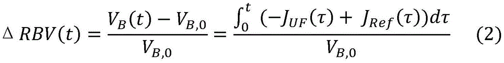


the glossary provides variable definitions.
Equation (1) defines the absolute blood volume VB(t) and streamThe relationship between the speeds.
Equation (2) defines the absolute blood volume VB(t) relative blood volume Δ rbv (t). Equation (3) describes Δ rbv (t) in differentiated form. J. the design is a squareUF(t) is known and may be provided to the controller 65 of the sensor 50 by the extracorporeal blood treatment apparatus 1, i.e. by the control unit 10.
NaPl(t) is calculated according to equation (4), wherein NaIn(t) and JREF(t) determined by experiment, VB(t) is calculated from equation (2), KDiff(membrane diffusivity for sodium) can be set to a typical value of 250 milliliters per minute (ml/min) or based on the membrane used. Na (Na)PlThe calculation of (t) requires an initial value. Calculation of NaPlPreliminary attempts at (t) reveal the presence of treatment-period-specific offsets associated with events during the treatment period, such as instrument recalibration and sodium electrode replacement. Therefore, in the calculation of NaPl(t) applying a baseline adjustment to account for the offset.
State space modeling and estimation
Selecting a state space approach to estimate Δ RBV (t) and NaPl(t), Δ RBV (t) and NaPl(t) is considered to be a state variable that fully describes the system under observation. The modeling equations describe the evolution of the state variables and the input/output relationships. As will be apparent from the following description, the estimation is done using kalman filtering techniques applied to the modeling equations. The classification of whether sensor data is input or output depends on whether the particular variable monitored by each sensor interferes with or is determined by the system state. Sodium concentration Na in the inlet dialysateIn(t) and inlet dialysate conductivity σIn(t) constitutes an input variable. Since the operator usually sets the inlet dialysate conductivity σIn(t) or the concentration of an electrolyte (e.g., sodium), so these input variables are known. Once one variable is set, the other variable will be automatically determined. Furthermore, the inlet dialysate conductivity σ can be measuredIn(t) and sodium concentration in the inlet dialysate NaIn(t) one or both of (a) and (b). For example, the second probe 109 of fig. 1 and 2 can be a conductivity meter, thereby measuring the inlet dialysate conductivity σ over timeIn(t)。
Mixing Na with hemodialysis machineInThe effective value of (t) remains within clinically acceptable boundaries of the operator-set value. Due to the general nature of the electrolyte solution and the fact that sodium is the highest concentration electrolyte in plasma and dialysate, a good correlation between the conductivity and sodium concentration of the two fluids can be found. Output sensor data by (optical) output Δ RP1(t) to Δ RP1(t) and outlet conductivity σOut(t) composition. Notably, the outlet conductivity σOut(t) can be measured by the extracorporeal blood treatment apparatus using an auxiliary conductivity meter 112 placed in the spent dialysate line 13.

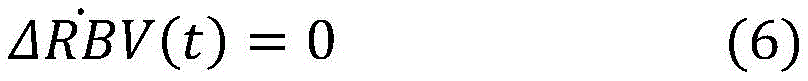
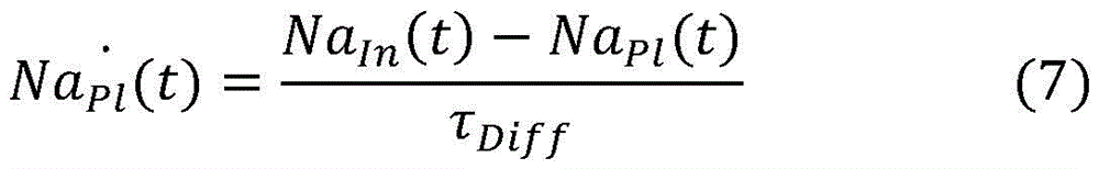
Ordinary differential equations (6) and (7) model blood pool dynamics (blood pool dynamics) and are obtained by removing from equations (3) and (4) the term (V) with parameters unknown during clinical practiceB,0,JRef,NaRef) And developed. One key part of the estimation process is the processing of non-modeling terms: due to the nature of the kalman filter, the absence of certain terms (i.e., terms included in equations (3) - (4) but not included in equations (6) - (7)) may be interpreted as noise in the modeling process. Thus, although the refill attribute and the starting blood volume are not known exactly, their influence on the reliability of the estimation is taken into account.
Although equation (3) is a better theoretical explanation, V is not yet known in clinical routineB,0And JRef(t) of (d). By employing an approximate version according to equation (6), the time-dependent variation of Δ RBV is not predictedThe kalman filter technique, however, includes a measurement-based correction step that is applied to model prediction. The correction is applied to the static Δ RBV value at each time step, making Δ RBV a quasi-static variable.
Equation (7) approximates equation (4): parameters of the refill process are not clinically available during treatment, and therefore, by using the diffusion time constant τ aloneDiffDescription of plasma sodium and NaIn(t) to model sodium dispersion. Tau isDiffCan be viewed as estimating V from equation (5)B(t)/KDiff. For KDiff250ml/min (actual value of sodium) and VBAs 5l (time-independent average), we obtained By adjusting the outlet conductivity σOut(t) fitting the first step response to the experimental data to obtain
 Is estimated. Thus, intermediate values may be used in the filter model
ΔRPi(t)=GOpt,i,1·ΔRBV(t)+GOpt,i,2·NaPl(t)+GOpt,i,3 (8)

Can be Δ RP described in equation (8)i(t) a linear formula is selected, where i 1. [4X3 ] in equation (9)]Matrix G ofOptIncluding the weighting coefficients of all channels of the signal detector, which are estimated by multiple regression analysis.

σOut(t)=GMix·σPl(t)+(1-GMix)·σIn(t-τDelay) (11)
σPl(t)=GNa,Gain·NaPl(t)+GNa,Offset (12)
The last output element (i.e. the outlet dialysate conductivity σ)Out(t)) was modeled as a weighted average of the inlet conductivity and plasma conductivity. In equation (10), σOutBased on the dialysis rate D and the dialysate flow rate JDIs calculated as the weighted average of (a). In equation (11), a simpler formula is derived from the previous equation, where GMix=D/JD. As an approximation, JDCan be fixed at 500ml/min and given an average value D of 250ml/min, a mixing constant G of value 0.5 can be appliedmix. Including a delay term τdelayTo illustrate the variation in travel time of dialysate constituents across the inlet of the hydraulic circuit. By measuring σ during the treatment period using a step in sodium concentrationOut(t) step response delay, estimating taudelayValue of (τ)delay=140s)。
The plasma conductivity σ is expressed in equation (12)Pl(t) modeling as plasma sodium concentration NaPl(t) is a linear function. Coefficient GNa,GainAnd GNa,OffsetEstimated by linear regression starting from experimental data.
Fig. 8 shows the relationship between input signals, state variables and output signals. Hemodialysis machines periodically enter bypass mode for safety reasons or for internal recalibration purposes. During the bypass period, ultrafiltration is suspended and the hydraulic connection of the dialysate to the hemodialyzer is short-circuited, see fig. 6 (dashed line), which means the data (σ) from the conductivity cellIn(t),σOut(t)) is not useful in the bypass state because the fresh dialysate at the inlet is directed to the sewer line directly without entering the filtration unit. Given the bypass state, certain changes to the modeling equations are required to reflect this temporary change to the physical system. Temporary in ultrafiltration during bypassStop means JUF(t) ═ 0, and, in view of the lack of involvement of J in clinical practiceRef(t) information, equation (6) is still the best available approximation for Δ RVB modeling. Therefore, equation (6) is retained and not replaced. Hydraulic disconnection of the filtration unit (e.g. hemodialyzer) during bypass means that dispersion is suspended, here modeled by replacing equation (7) with equation (13) below:

for NaPlThe modification of the process noise of (t) reflects this temporary replacement. During bypass, the data from the conductivity cell is not useful due to the different hydraulic path of the dialysate (which is not directed to the fluid chamber of the filtration cell). This is achieved by the bypass period being equal to sigmaIn(t) and σOut(t) the sensitivity of the associated filter is set to zero to reflect. FIG. 9 depicts a transition model for tuning the Kalman filter to switch between standard mode, bypass mode and accumulation mode. During accumulation mode, the alteration of the filter structure associated with the bypass state remains for an additional period of time τDelayTo allow accumulation of necessary sigma before returning to default filter operationIn(t) a delay.
Kalman filtering is basically the following algorithm: using a series of measurements observed over time, including statistical noise and other inaccuracies (e.g. due to equation simplification), and generating estimates of the unknown variables by estimating the joint probability distribution of these variables within each time range (timeframe), these estimates tend to be more accurate than those based on a single measurement alone. The algorithm proceeds in a two-step process. In the prediction step, the kalman filter generates an estimate of the current state variables and their uncertainties. Once the results of the next measurement are observed (necessarily corrupted by a certain amount of error, containing random noise), the estimates are updated using a weighted average, where estimates with high certainty are given higher weight. The algorithm is recursive and can run in real time using only the current input measurements and the previously computed states and their uncertainty matrices, without requiring other information.
The following equations (14) to (18) define examples of kalman filters that can be employed according to the present embodiment.


These equations above are given as a function of the general time step k. For example, a time step of 1s may be selected. Equations (14) and (15) represent the prediction step, where the modeling knowledge of the system is employed, and equations 16 to 18 represent the measurement-based correction steps.
Input ukIs [2x1]Vector of (a), which includes NaIn[k]And σIn[k]. Vector xk -And xk +(all are [2x1 ]]Vector of) contains a state variable Δ RBV [ k ]]And NaPl[k]The predicted value and the corrected value of (c). x is the number ofk -Is the predicted system state at step k, and is xk-1 +And ukFunction f (·, ·,). Initial vector x0 +May be set to Δ RBV ═ 0 and Na Pl140 mM. In other words, the initial vector includes the change in empty blood volume and the subject's mean plasma sodium concentration.
In standard mode, the function f (·,) is defined by the discretized versions of equations (6) and (7), while in bypass mode, it is defined by discretized equations (6) and (13). The discretization of equations (6), (7) and (13) is achieved by the forward euler method, respectively; the discretized equations are respectively:
ΔRBV[k]=ΔRBV[k-1] (19)

NaPl[k]=NaPl[k-1] (21)
in the bypass state, equation 21 is used instead of equation 20. [2X2]The matrix Q describes the process noise covariance. Matrix A is f (·,) for Δ RBV and NaplOf [2x2]Jacobian linearization of.
Standard QstdThe matrix is used during standard filter operation, and is replaced by Q during bypass modebypass. Both versions of Q are diagonal matrices whose elements are pre-computed based on the actual maximum of the non-modeled term of the process equation. Error gain EkIs [2x 5] calculated according to equation (16)]Of the matrix of (a).
The measurement noise is characterized by [5x5]]Is considered as a predetermined diagonal matrix. The diagonal values of R associated with the optical measurements are set equal to the root mean square fit residual of equation (9). The sum σ of R is selected based on the actual deviation of D from the mean value considered for equation (11)OutAssociated diagonal values are modeled.
Observation vector ZkIs the experimentally measured system output of [5x1]By the optical output Δ RP1[k]To Δ RP4[k]And outlet conductivity σOut[k]And (4) forming. g (x)k -,uk) Is the predicted output [5x1 ] calculated from the state output function g (·,)]The column vector of (2). The function g (·, ·) is determined by the time-discrete versions of equations (9) and (11), which are given below, respectively:
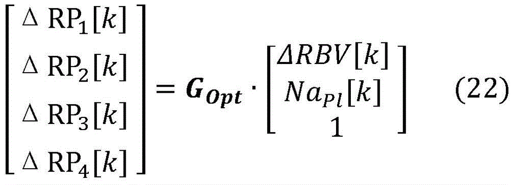
σOut[k]=GMix·σPl[k]+(1-GMix)·σIn[k-kDelay] (23)
in equation (23), kDelayIs τDelayAnd σ is calculated according to the following equationPl[k]:
σPl[k]=GNa,Gain·NaPl[k]+GNa,Offset (24)
This is a discretized version of equation (12).
The matrix H from equations (16) and (18) is for Δ RBV and NaplG (·,.) of [5x2]And (5) carrying out Jacobian linearization. There are two versions of H: hstdAnd Hbypass. During default machine operation, H is usedstd. During the bypass, H isstdIs replaced by HbypassTo ensure that the correction step pair σ is based on the measurementIn[k]And σOut[k]It is not sensitive.
Matrix Pk -And Pk +Predicted and corrected 2x2 respectively]The covariance is estimated. These two matrices are calculated at each step k according to equations (15) and (18), from Δ RBV and NaP1Is set to a diagonal matrix P of 0 and 4mM+Initialization is performed. The zero uncertainty of the starting Δ RBV is derived from the fact that: Δ RBV is a relative change and its starting value is always known and equal to 0. Na (Na)PlIs based on the following assumptions: the physiological range of the patient at the start of the treatment was 136-144 mM.
Considering P+Representing the covariance, P, of the state variables+Is an important feature of the kalman filter. The estimated covariance is affected by the covariance of the modeling and measurement processes as described in equations (15) and (18). On this basis, P is a useful additional source of information about the uncertainty of the estimate: we choose to use P from equation (18)+Pair ofCorner element P11And P22Is used as an index of uncertainty to derive a confidence interval And
And
the use of simplified blood pool model equations and Kalman filter methods allows the state variables to be determined and monitored over time, i.e., the system knows the relative blood volume change Δ RBV and the plasma sodium concentration NaplAnd updated at each timestamp k. Knowledge of blood parameters in substantially real time allows the extracorporeal blood treatment machine to determine other relevant treatment aspects, such as filter efficiency and/or to follow more accurately the correct analysis of patient values.
According to the above aspect, the controller 65 is configured to calculate the concentration of sodium present in the fluid flowing through said section 61 of the extracorporeal blood circuit 60 based on the output signal received by the detector 57. For example, if the segment is part of a blood withdrawal line and the fluid is blood, the controller 65 may continuously determine the concentration of sodium present in the blood flowing through the blood withdrawal line, while if the segment is part of a blood return line and the fluid is blood, the control unit or detection circuitry may continuously calculate the concentration of sodium present in the blood flowing through the blood return line.
Na of the blood circulating in the extracorporeal circuit may be calculated (e.g., by controller 65)plAnd the change in blood volume (independent of osmotic pressure) is determined.
Further, the controller 65 (or the device control unit 10, respectively) may be configured to: at least one value of a parameter (D, K · t) indicative of the effectiveness of the extracorporeal blood treatment is determined based on a measurement of the plasma sodium concentration of the blood circulating in the tube segment (e.g. based on a determination of the plasma sodium concentration during the extracorporeal blood treatment).
In detail, the controller 65 may be configured to command the following steps:
once the extracorporeal circuit is correctly mounted in the respectiveIs connected to the patient such that the patient's blood is at a blood flow rate Q (e.g., acting on the blood pump 11)bFlows in the extracorporeal blood circuit 60;
fresh treatment liquid is made to flow in the preparation line 19 at a flow rate (Qd)in) Towards the auxiliary chamber 4;
this can be achieved, for example, by operating the pump 21 and, in the case of a device comprising a preparation section 100, this section is suitably also equipped with pumps 105 and 108;
flow rate Qd of used treatment liquidoutFlows in the spent dialysate line 13; this may be achieved by operating pump 17 and optionally pump 27;
the conductivity (σ) of the substance receiving fresh treatment liquid flowing in the preparation line 19in) Or concentration (Na)in) The associated one or more values; the substance may be a single element (e.g., an electrolyte) or may be a group of elements, such as a collection of electrolytes: for example, the sensor 109 may provide information to the control unit 10 relating to the conductivity or concentration of a given substance (e.g., sodium); or a set value of the conductivity or concentration of the substance may be used;
the conductivity (σ) of the substance received and in the used treatment fluid flowing in the spent dialysis fluid line 13out) Or concentration (Na)out) The associated one or more measurements; the sensor 112 is capable of detecting conductivity or concentration; for example, a conventional concentration or conductivity sensor may provide information to the control unit 10 relating to the conductivity or concentration of a given substance;
calculating at least one parameter value (D, K.t) indicative of the effectiveness of the extracorporeal blood treatment, according to:
the conductivity (σ) of the used treatment liquid with the substanceout) Or concentration (Na)out) The one or more measured values of correlation
Conductivity (σ) of said substance of fresh treatment liquidin) Or concentration (Na)in) The one or more set points or measured values of (a);
the blood flowing through the extracorporeal blood circuit 60Plasma conductivity σ of the substance in the blood of paragraph 61plOr plasma sodium concentration NaplThe calculated value of (a);
at least one of the following: said flow rate Qd of fresh treatment liquidinAnd said flow rate Qd of used process liquidout。
Alternatively, the device may comprise at least two of the above-mentioned electrical parameter sensors 50: each of these two sensors 50 will have the characteristics of sensor 50 described above, in which the first tubular section 61 of the blood withdrawal line is housed in the body of the housing of the first of said two sensors 50 and the second tubular section 61 of the blood return line is housed in the body of the housing of the second of said two sensors 50. In this alternative, the controller 65 (connected to each blood/plasma parameter sensor 50) may be configured to:
once the extracorporeal circuit has been correctly mounted on the respective support and connected to the patient, the patient's blood is brought to a blood flow rate Q (acting on the blood pump 11, for example)bFlowing in an extracorporeal blood circuit;
fresh treatment liquid in the preparation line 19 at a flow rate QdinFlow to the auxiliary chamber 4; this can be achieved, for example, by operating the pump 21 and, in the case of a device comprising a preparation section 100, this section is suitably also equipped with pumps 105 and 108;
the flow rate Qd of the used treatment liquid in the waste dialysate line 13outFlowing; this may be achieved by operating pump 17 and optionally pump 27;
the conductivity (σ) of the substance receiving fresh treatment liquid flowing in the preparation line 19in) Or concentration (Na)in) The associated one or more values; the substance may be a single element (e.g., an electrolyte) or may be a group of elements, such as a collection of electrolytes: for example, the sensor 109 may provide information to the control unit 10 relating to the conductivity or concentration of a given substance (e.g., sodium); or a set value of the conductivity or concentration of the substance may be used;
using a mounting as just described for blood drawingTaking two sensors 50 on the line and on the blood return line to receive or calculate the conductivity (σ) of said substance in the blood flowing in said first section (61)pl,in) Or concentration (Na)pl,in) And the electrical conductivity (σ) of said substance in the blood flowing in said second segment 61pl,out) Or concentration (Na)pl,out) A value of (d);
calculating at least one parameter value (D, K.t) indicative of the effectiveness of the extracorporeal blood treatment, according to:
conductivity (σ) of said substance of fresh treatment liquidin) Or concentration (Na)in) The one or more values of (a);
the conductivity (σ) of said substance in the blood flowing in said first section (61)pl,in) Or concentration (Na)pl,in) And the electrical conductivity (σ) of said substance in the blood flowing in said second segment (61)pl,out) Or concentration (Na)pl,out) The value of (a) is,
the blood flow rate (Q)b)。
Note that in knowing the plasma sodium concentration NaplIn this case, the electrical conductivity of the fluid (blood) in the extracorporeal blood circuit can be determined. The step of flowing fresh process liquid in the preparation line 19 comprises the sub-steps of: maintaining the concentration of the substance (Na) in the fresh treatment fluid for at least the time interval Tin) Or electrical conductivity (σ)in) Is constant at a set value, during which time interval a measurement of the conductivity or concentration is made, which set value is used to calculate at least one value of a parameter D, K · t indicative of the effectiveness of the extracorporeal blood treatment. At least during said time interval T, the control unit 10 is configured to keep constant: flow rate Qd of fresh process liquid in preparation line 19inFlow rate Qb of the patient's blood in the extracorporeal blood circuit, and flow rate Q of the ultrafiltration flow through the semipermeable membraneF。
In fact, no change in conductivity is required to achieve a determination of the dialysance or dialysis dose.
In further detail, the parameter indicative of the effectiveness of the extracorporeal blood treatment is the dialysance D of the substance, which is calculated using one of the following formulae:


Wherein

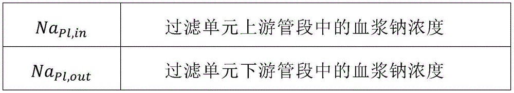
Once the dialysance has been calculated, the instantaneous values of dialysance can be integrated over time in order to determine the value of K · t in a manner known per se and will not be described in detail here.
The invention also relates to a process for determining blood or plasma parameters using a sensor 50 and/or a device for extracorporeal treatment of blood, such as disclosed above or as claimed in any one of the appended claims. Fig. 14 shows the main steps of the process, including: sending a signal towards the extracorporeal blood and receiving a reflected signal, a transmitted signal and/or a scattered signal by means of receivers placed around the tube segment in different angular positions. The process comprises the following steps: determining (as described above) a blood property (e.g. blood volume change Δ RBV) and/or an auxiliary blood parameter (e.g. Na)pl). The procedure for determining blood properties and auxiliary blood parameters is illustrated in fig. 8, where the input signal is shownThe relation between the state variable and the output signal; the dashed line represents an unreliable connection during bypass mode. These aspects provide additional details regarding the implementation of the process.
Control unit
As already indicated, the device according to the invention makes use of the control unit 10 and at least one controller 65 of the sensors. It is noted that the controller 65 of the sensor 50 may be part of the control unit 10 (software and/or hardware part) of the extracorporeal blood treatment apparatus or may be a separate processing unit.
Both the control unit 10 and the controller 65 may comprise a digital processor (CPU) with memory, analog circuitry, or a combination of one or more analog processing circuits and one or more digital processing units. In the present description and claims it is indicated that the control unit/controller is "configured" or "programmed" to perform certain steps: in practice this may be achieved by means allowing the control unit/controller to be configured or programmed. For example, where the control unit/controller includes one or more CPUs, one or more programs are stored in a suitable memory: the program contains instructions which, when executed by the control unit/controller, cause the control unit to perform the steps described and/or claimed in connection with the control unit/controller. Alternatively, if the control unit/controller is of an analogue type, the circuitry of the control unit/controller is designed to comprise circuitry configured to process the electrical signals in use in order to perform the control unit/controller steps disclosed herein.
Procedure of experiment
Having Δ RVB and/or NaPlThe protocol of the perturbed extracorporeal hemodialysis treatment session is designed to collect robust and representative data to develop and validate the estimation apparatus and method presented and described above.
Fresh heparinized bovine blood and the hemodialysis machine (produced by Baxter of medola, italy) performed 12 extracorporeal hemodialyses. At each timeImmediately prior to dialysis, hematocrit was measured using capillary centrifugation and the blood was diluted with saline solution to reach a hematocrit of 30%. For each session, the starting blood volume is VB,05 l. Blood flow rate JBAnd dialysate flow rate JDIs set to a typical clinical value, i.e., JB300ml/min and JD=500ml/min。
During clinical hemodialysis, the removal of water from the patient's blood pool is partially compensated for by refilling (a phenomenon in which fluid is transferred from other body chambers to the circulatory system to maintain physiological blood pressure). During the session, refilling is simulated by using a peristaltic pump and a fresh dialysate container, the chemical composition of the fresh dialysate is similar to plasma. Please see the schematic diagram of the setup of fig. 4.
By setting the ultrafiltration rate to JUFSet the refill rate to J at 0.8L/hRef0.63L/h to achieve relative blood volume loss. The difference between these flows allowing the physiology to end the treatment session

By adding sodium concentration Na to the inlet dialysateInApplying a step to achieve plasma sodium concentration NaPlA change in (c). Na (Na)InIs transmitted to Na by diffusion across the membrane of the haemodialysis machinePlSo that it can be approximated as a first order response. The concentration was initially set at 140mM and two steps of. + -.7 mM were then applied (relative to 140mM reference) before returning to 140 mM. Each concentration value was maintained for 45 minutes. The order of the positive and negative steps may be changed between sessions. This scheme is shown in figure 5.
Each session consisted of a1 hour conditioning phase followed by a 3 hour experimental phase. The conditioning phase is designed to achieve a balance between dialysate and blood to improve the repeatability of the experimental session, as each fresh volume of bovine blood may carry a different plasma concentration of electrolytes. During the conditioning phase, NaInAnd remain constant. In this way, the blood can reach the standard initial conditions before the actual experiment starts. By setting J in this stageUF=JRefThe achievement of the electrolyte concentration balance can be accelerated at 0.8L/h, and thus the blood volume is kept constant. For purposes of illustration, t-0 indicates the start of the 3 hour experimental phase. Eight sessions were performed by ultrafiltration, refill and sodium steps. With JUF=JRefTwo sessions were conducted to evaluate Na at 0PlIsolated effect of changes on the measurement system. With constant NaInConcentration two sessions were conducted to evaluate the isolated effect of Δ RBV. In the last two sessions, one with NaPl(0)=NaRef140mM and the other NaPl(0)=NaRef145mM was performed to mimic actual cases in hypernatremic patients.
Samples for blood gas analysis (indicated by black dots in fig. 5) were taken at the beginning and end of the session and every 45 minutes in between. The electrolyte concentration was determined using a Stat Profile pHOx Ultra blood gas analyzer (Nova biomedicalal, waltham, USA). At the end of each session, an internal session log of the hemodialysis machine is downloaded to access internal sensor data (ultrafiltration rate J)UFDialysate inlet conductivity σInConductivity sigma of dialysate outletOut) See fig. 6.
Data recorded from the optical measurement system was median filtered to remove artifacts (10 sample window) and then smoothed by moving average (5000 sample window). The data from the 3 hour experimental period was then converted to relative optical power change according to the following equation:

wherein, VOut,i(t) is the recorded analog voltage output, i represents the output channel.
Signal JUF(t),σIn(t) and σOut(t) is a session recorder by an extracorporeal blood treatment machine with FSRecorded at 0.1 Hz. ToIn the optical data, only data from the 3 hour experimental period were analyzed. Signal JUF(t) median filtering (5 sample windows) is performed to remove artifacts, whereas σIn(t) and σOut(t) smoothing is performed by moving average filtering (5 sample windows).
Throughout the session, the hemodialysis machine may be temporarily switched to bypass mode for safety reasons or for internal recalibration purposes. During the bypass period, ultrafiltration is suspended and the hydraulic connection of the dialysate to the hemodialyzer is short-circuited, see fig. 6 (dashed line), which means the data (σ) from the conductivity cellIn(t),σOut(t)) is not useful in the bypass state because the fresh dialysate at the inlet is directed to the sewer line directly without entering the filtration unit. Using the process log, a binary signal is established for each session indicating whether conductivity data is available at any given time.
Blood gas analysis was used to determine the experimental plasma sodium concentration Na at t 0, 45, 90, 135 and 180 minutesPl,Exp(t) of (d). Three analyses were performed on each sample to obtain an average, but the first measurement in each set of three consistently showed a negative bias, while the other two agreed between them. Thus, for each blood sample, Na will bePl,ExpThe value of (t) is calculated as the average of the second measurement and the third measurement. A possible explanation is that the first measurement is taken after a period of inactivity of the analyzer, and that the operating conditions of the instrument may be slightly different.
Results of the Experimental procedures
As described above, the parameter G in equation (9)OptAnd G in equation (12)Na,GainAnd GNa,OffsetNot based on modeling assumptions, but are fitted to experimental data. Thus, the performance of the system can be evaluated in two ways. To determine the best performance, a version of the kalman filter with empirical parameters fitted to the entire data set is used to calculate the estimation error. Furthermore, to evaluate the robustness of the estimator, a leave-one-out procedure was adopted for the 12-session data set: for each iteration, 11 sessions were used for the fitting, and 1 was tested.
For Δ RBV and NaPlThe two calculate an estimation error as the absolute difference between the reference data and the estimated value. First, the average and maximum error are calculated for each session; the mean ± standard deviation between sessions is then calculated for both mean and maximum error. The results are reported in table I below.
Table I results of the estimation procedure
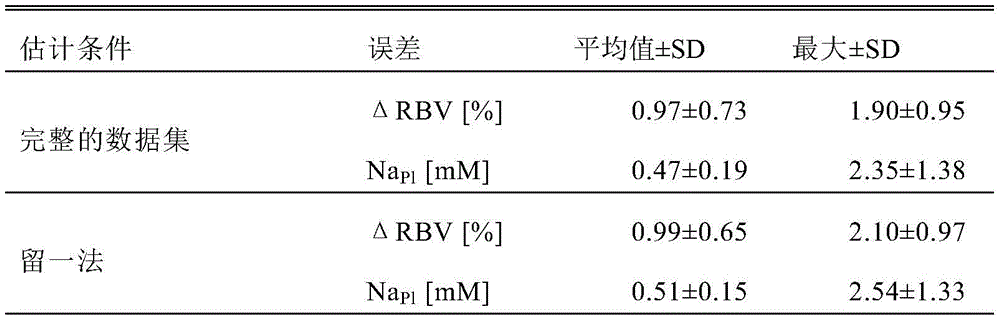
In estimating Δ RBV and NaPlThe kalman filter, tuned by data from the entire data set, showed good performance.
The estimation error evaluated by the leave-one-out procedure exhibits only small differences compared to the evaluation of the entire data set, especially when large standard deviations are taken into account. The results show that the fitting process is not sensitive to data from one session in particular and that the reliability of the proposed filter architecture is demonstrated.
Fig. 10 illustrates the state estimation result in the best case when the parameters of the estimator are calculated using data from the complete data set. The following experiments show Δ RBV and NaPlEstimation of (2): the experiments with a blood volume loss and a step in sodium concentration (fig. 10(a) and 10(d), respectively), the experiments with a blood volume loss close to zero (fig. 10(b) and 10(e)), and the experiments simulating the starting hypernatremia patient condition (fig. 10(c) and 10 (f)). The switch from standard filter operation to bypass mode is indicated by the temporary transition to solid dark grey line. Fig. 10(a) - (c) show the results of estimating relative blood volume loss. Although there is still some difference between the estimated blood volume loss and the reference blood volume loss, NaPlDoes not show any discernible influence on the Δ RBV sum signal. This feature is visible in all experimental links and indicates that the goal of osmolarity-sensitive Δ RBV estimation has been reached. FIG. 10(f) is an example of the reliable behavior of the estimator, even when the starting conditions are not ideal: simulating starting blood of a patientThe slurry sodium concentration is also much higher than the initial estimate of the kalman filter (145vs140 mM). Nevertheless, the estimator may still drive Na in the direction of the experimental valuesPlIs estimated. Less than 10 minutes after the session starts, by The confidence interval of the given estimate already comprises reference data. Such short time period is associated with NaPlThe estimated clinical utility is largely compatible.
Due to the nature of the Kalman Filter Algorithm, P is updated for each step+The matrix tends to converge to a steady state value. As is evident from the dynamic variation of the estimated boundary interval shown in fig. 10, in the first few minutes of filter operation Inner, P+A steady state is reached very quickly.
While the invention has been described in connection with what is presently considered to be the most practical and preferred embodiment, it is to be understood that the invention is not to be limited to the disclosed embodiment, but on the contrary, is intended to cover various modifications and equivalent arrangements included within the spirit and scope of the appended claims.
Claims (34)

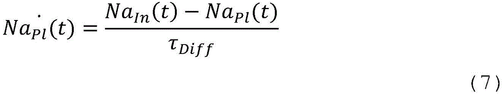


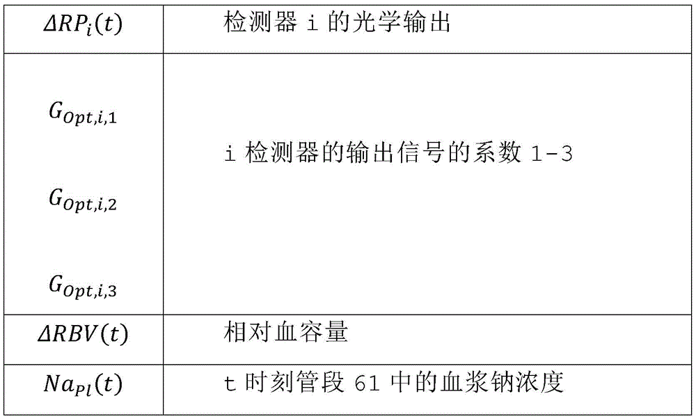

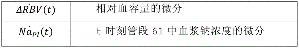
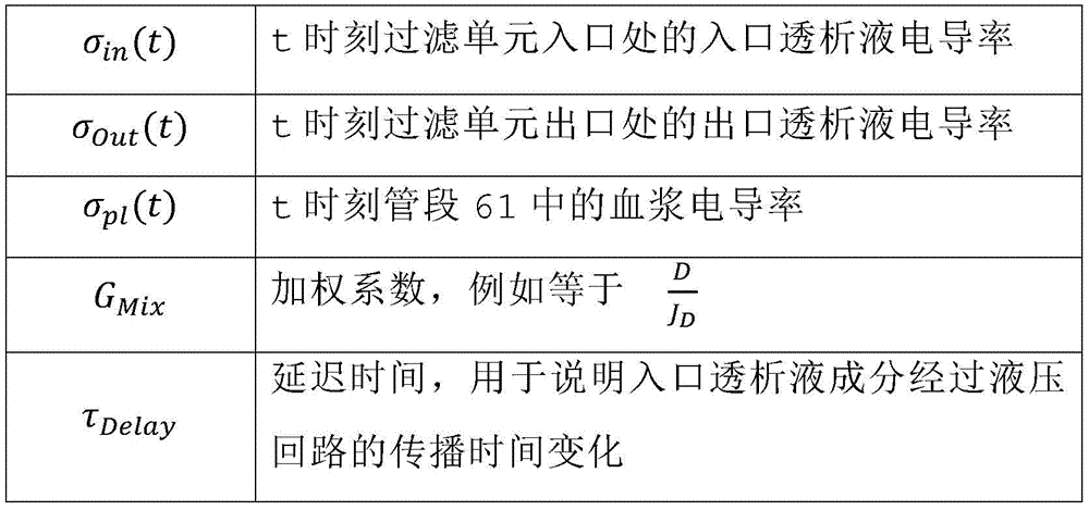
Priority Applications (1)
| Application Number | Priority Date | Filing Date | Title |
|---|---|---|---|
| CN202410944650.5A CN118831214A (en) | 2018-03-20 | 2019-03-20 | Sensor and device for determining at least one parameter of blood circulating in an extracorporeal blood circuit |
Applications Claiming Priority (3)
| Application Number | Priority Date | Filing Date | Title |
|---|---|---|---|
| EP18162977.5A EP3542707A1 (en) | 2018-03-20 | 2018-03-20 | Sensor and apparatus for determining at least one parameter of blood circulating in an extracorporeal blood circuit |
| EP18162977.5 | 2018-03-20 | ||
| PCT/EP2019/056938 WO2019180068A1 (en) | 2018-03-20 | 2019-03-20 | Sensor and apparatus for determining at least one parameter of blood circulating in an extracorporeal blood circuit |
Related Child Applications (1)
| Application Number | Title | Priority Date | Filing Date |
|---|---|---|---|
| CN202410944650.5A Division CN118831214A (en) | 2018-03-20 | 2019-03-20 | Sensor and device for determining at least one parameter of blood circulating in an extracorporeal blood circuit |
Publications (2)
| Publication Number | Publication Date |
|---|---|
| CN112203578A true CN112203578A (en) | 2021-01-08 |
| CN112203578B CN112203578B (en) | 2024-08-02 |
Family
ID=61731640
Family Applications (2)
| Application Number | Title | Priority Date | Filing Date |
|---|---|---|---|
| CN201980034190.XA Active CN112203578B (en) | 2018-03-20 | 2019-03-20 | Sensor and device for determining at least one parameter of blood circulating in an extracorporeal blood circuit |
| CN202410944650.5A Pending CN118831214A (en) | 2018-03-20 | 2019-03-20 | Sensor and device for determining at least one parameter of blood circulating in an extracorporeal blood circuit |
Family Applications After (1)
| Application Number | Title | Priority Date | Filing Date |
|---|---|---|---|
| CN202410944650.5A Pending CN118831214A (en) | 2018-03-20 | 2019-03-20 | Sensor and device for determining at least one parameter of blood circulating in an extracorporeal blood circuit |
Country Status (8)
| Country | Link |
|---|---|
| US (2) | US12029555B2 (en) |
| EP (2) | EP3542707A1 (en) |
| JP (2) | JP7322055B6 (en) |
| KR (2) | KR102733384B1 (en) |
| CN (2) | CN112203578B (en) |
| AU (2) | AU2019238375B2 (en) |
| CA (1) | CA3094271A1 (en) |
| WO (1) | WO2019180068A1 (en) |
Cited By (2)
| Publication number | Priority date | Publication date | Assignee | Title |
|---|---|---|---|---|
| CN113476674A (en) * | 2021-06-30 | 2021-10-08 | 江苏森宝生物科技有限公司 | Electromagnetic compatibility method for hemodialysis equipment |
| WO2023045425A1 (en) * | 2021-09-23 | 2023-03-30 | 重庆山外山血液净化技术股份有限公司 | Method and system for evaluating risk of intradialytic hypotension event |
Families Citing this family (14)
| Publication number | Priority date | Publication date | Assignee | Title |
|---|---|---|---|---|
| EP3990049A1 (en) | 2019-06-26 | 2022-05-04 | Gastroklenz Inc. | Systems, devices, and methods for fluid monitoring |
| AU2020347867B2 (en) | 2019-09-19 | 2025-07-10 | Gambro Lundia Ab | Non-invasive sensor for determining a heartbeat and/or heart rate in a segment of an extracorporeal blood circuit |
| EP3842085B1 (en) * | 2019-12-24 | 2023-09-27 | Gambro Lundia AB | Apparatus for extracorporeal blood treatment |
| US20230018177A1 (en) * | 2019-12-31 | 2023-01-19 | Nuwellis, Inc. | Blood filtration system and plasma volume monitoring |
| IT202000006706A1 (en) * | 2020-03-31 | 2021-10-01 | Medica S P A | BLOOD FILTRATION MACHINE EQUIPPED WITH A MEASURING SYSTEM INCLUDING OPTICAL SENSORS |
| WO2021205389A1 (en) * | 2020-04-09 | 2021-10-14 | Renalyx Health Systems Private Limited | Method and device for providing personalised haemodialysis for a subject |
| FI129302B (en) * | 2020-09-21 | 2021-11-30 | Paree Group Oy | Apparatus and method for measuring blood in liquid |
| JP2023056972A (en) * | 2021-10-08 | 2023-04-20 | 日機装株式会社 | blood purifier |
| DE102021132841A1 (en) * | 2021-12-13 | 2023-06-15 | Fresenius Medical Care Deutschland Gmbh | Blood treatment machine for extracorporeal blood treatment and system for detecting blood or blood components in a hose line |
| WO2023235005A1 (en) * | 2022-05-31 | 2023-12-07 | Boundless Science Llc | Method and apparatus for enhanced transport |
| DE102022124946A1 (en) * | 2022-09-28 | 2024-03-28 | Fresenius Medical Care Deutschland Gmbh | Blood leak detector system and blood treatment machine for extracorporeal blood treatment |
| JP7408868B1 (en) | 2023-04-12 | 2024-01-05 | 日機装株式会社 | blood purification device |
| JP7408869B1 (en) | 2023-04-12 | 2024-01-05 | 日機装株式会社 | blood purification device |
| WO2024226488A2 (en) * | 2023-04-24 | 2024-10-31 | Neuro-Vascular Research and Design Corporation | Systems and method for monitoring penile blood flow during surgery |
Citations (11)
| Publication number | Priority date | Publication date | Assignee | Title |
|---|---|---|---|---|
| US5331958A (en) * | 1992-03-31 | 1994-07-26 | University Of Manitoba | Spectrophotometric blood analysis |
| EP0845273A1 (en) * | 1996-11-30 | 1998-06-03 | Fresenius Medical Care Deutschland GmbH | Method and means for in vivo determining haemodialysis parameters |
| US20030023170A1 (en) * | 2001-04-11 | 2003-01-30 | Craig Gardner | Optically similar reference samples and related methods for multivariate calibration models used in optical spectroscopy |
| US20110269167A1 (en) * | 2010-05-03 | 2011-11-03 | Gambro Lundia Ab | Medical apparatus for extracorporeal blood treatment and method for determining a blood parameter value in a medical apparatus thereof |
| US20130199998A1 (en) * | 2011-08-02 | 2013-08-08 | Medtronic, Inc. | Hemodialysis system having a flow path with a controlled compliant volume |
| CN103547299A (en) * | 2011-03-21 | 2014-01-29 | 甘布罗伦迪亚股份公司 | An apparatus for extracorporeal blood treatment |
| CN103547300A (en) * | 2011-03-21 | 2014-01-29 | 甘布罗伦迪亚股份公司 | An apparatus for extracorporeal blood treatment |
| EP2823834A1 (en) * | 2013-07-10 | 2015-01-14 | Gambro Lundia | Apparatus for extracorporeal blood treatment |
| CN104321088A (en) * | 2012-11-14 | 2015-01-28 | 甘布罗伦迪亚股份公司 | Device for determining parameters indicative of progress in extracorporeal blood treatment |
| US20150305658A1 (en) * | 2012-12-31 | 2015-10-29 | Omni Medsci. Inc. | Near-infrared lasers for non-invasive monitoring of glucose, ketones, hba1c, and other blood constituents |
| CN107660154A (en) * | 2015-05-25 | 2018-02-02 | 甘布罗伦迪亚股份公司 | Equipment for extracorporeal blood treatment I |
Family Cites Families (14)
| Publication number | Priority date | Publication date | Assignee | Title |
|---|---|---|---|---|
| SE465404B (en) | 1988-03-03 | 1991-09-09 | Gambro Ab | DIALYSIS SYSTEM |
| DE3938662A1 (en) | 1989-11-21 | 1991-07-18 | Fresenius Ag | METHOD FOR IN VIVO DETERMINING PARAMETERS OF HAEMODIALYSIS |
| FR2713937B1 (en) | 1993-12-17 | 1996-05-31 | Hospal Ind | Method for determining a significant parameter of the progress of an extracorporeal blood treatment. |
| IT1274841B (en) * | 1994-07-18 | 1997-07-25 | Bellco Spa | PERFECTED TYPE EQUIPMENT FOR DIALYSIS TREATMENTS. |
| JP3992159B2 (en) | 1997-01-24 | 2007-10-17 | フレセニウス メディカル ケア ドイチランド ゲーエムベーハー | Method for measuring hemodialysis parameters and apparatus for carrying out such a method |
| FR2771931B1 (en) | 1997-12-09 | 2000-01-07 | Hospal Ind | METHOD FOR DETERMINING A SIGNIFICANT PARAMETER OF THE PROGRESS OF AN EXTRACORPOREAL BLOOD TREATMENT |
| SE9804142D0 (en) | 1998-11-30 | 1998-11-30 | Gambro Ab | Method and device for providing a signal |
| US6691040B2 (en) | 1999-12-02 | 2004-02-10 | Hospal Ag | Method for determining a parameter indicative of the progress of an extracorporeal blood treatment |
| CN102186421B (en) * | 2008-10-17 | 2013-12-04 | 希森美康株式会社 | biological monitoring device |
| US8525533B2 (en) | 2010-09-16 | 2013-09-03 | Fresenius Medical Care Holdings, Inc. | Conductivity detector for fluids |
| US20170135633A1 (en) | 2013-05-23 | 2017-05-18 | Medibotics Llc | Integrated System for Managing Cardiac Rhythm Including Wearable and Implanted Devices |
| EP2687248B1 (en) | 2012-07-18 | 2014-10-29 | Gambro Lundia AB | Apparatus and method for determining a parameter indicative of the progress of an extracorporeal blood treatment |
| EP2745863B9 (en) * | 2012-12-20 | 2017-08-30 | Gambro Lundia AB | An apparatus for extracorporeal blood treatment |
| WO2015111931A1 (en) | 2014-01-22 | 2015-07-30 | 엘지전자 주식회사 | Method and device for transmitting uplink signal in wireless communication system |
-
2018
- 2018-03-20 EP EP18162977.5A patent/EP3542707A1/en active Pending
-
2019
- 2019-03-20 EP EP19712752.5A patent/EP3768151A1/en active Pending
- 2019-03-20 WO PCT/EP2019/056938 patent/WO2019180068A1/en not_active Ceased
- 2019-03-20 JP JP2020550599A patent/JP7322055B6/en active Active
- 2019-03-20 KR KR1020207029994A patent/KR102733384B1/en active Active
- 2019-03-20 US US16/982,317 patent/US12029555B2/en active Active
- 2019-03-20 CA CA3094271A patent/CA3094271A1/en active Pending
- 2019-03-20 KR KR1020247037755A patent/KR102858931B1/en active Active
- 2019-03-20 AU AU2019238375A patent/AU2019238375B2/en active Active
- 2019-03-20 CN CN201980034190.XA patent/CN112203578B/en active Active
- 2019-03-20 CN CN202410944650.5A patent/CN118831214A/en active Pending
-
2023
- 2023-07-26 JP JP2023121864A patent/JP7513811B2/en active Active
-
2024
- 2024-05-07 US US18/657,286 patent/US20240350040A1/en active Pending
- 2024-05-15 AU AU2024203229A patent/AU2024203229B2/en active Active
Patent Citations (12)
| Publication number | Priority date | Publication date | Assignee | Title |
|---|---|---|---|---|
| US5331958A (en) * | 1992-03-31 | 1994-07-26 | University Of Manitoba | Spectrophotometric blood analysis |
| EP0845273A1 (en) * | 1996-11-30 | 1998-06-03 | Fresenius Medical Care Deutschland GmbH | Method and means for in vivo determining haemodialysis parameters |
| US20030023170A1 (en) * | 2001-04-11 | 2003-01-30 | Craig Gardner | Optically similar reference samples and related methods for multivariate calibration models used in optical spectroscopy |
| US20110269167A1 (en) * | 2010-05-03 | 2011-11-03 | Gambro Lundia Ab | Medical apparatus for extracorporeal blood treatment and method for determining a blood parameter value in a medical apparatus thereof |
| CN103547299A (en) * | 2011-03-21 | 2014-01-29 | 甘布罗伦迪亚股份公司 | An apparatus for extracorporeal blood treatment |
| CN103547300A (en) * | 2011-03-21 | 2014-01-29 | 甘布罗伦迪亚股份公司 | An apparatus for extracorporeal blood treatment |
| US20130199998A1 (en) * | 2011-08-02 | 2013-08-08 | Medtronic, Inc. | Hemodialysis system having a flow path with a controlled compliant volume |
| CN104321088A (en) * | 2012-11-14 | 2015-01-28 | 甘布罗伦迪亚股份公司 | Device for determining parameters indicative of progress in extracorporeal blood treatment |
| US20150305658A1 (en) * | 2012-12-31 | 2015-10-29 | Omni Medsci. Inc. | Near-infrared lasers for non-invasive monitoring of glucose, ketones, hba1c, and other blood constituents |
| EP2823834A1 (en) * | 2013-07-10 | 2015-01-14 | Gambro Lundia | Apparatus for extracorporeal blood treatment |
| WO2015004030A1 (en) * | 2013-07-10 | 2015-01-15 | Gambro Lundia Ab | An apparatus for extracorporeal blood treatment and a related control method |
| CN107660154A (en) * | 2015-05-25 | 2018-02-02 | 甘布罗伦迪亚股份公司 | Equipment for extracorporeal blood treatment I |
Cited By (2)
| Publication number | Priority date | Publication date | Assignee | Title |
|---|---|---|---|---|
| CN113476674A (en) * | 2021-06-30 | 2021-10-08 | 江苏森宝生物科技有限公司 | Electromagnetic compatibility method for hemodialysis equipment |
| WO2023045425A1 (en) * | 2021-09-23 | 2023-03-30 | 重庆山外山血液净化技术股份有限公司 | Method and system for evaluating risk of intradialytic hypotension event |
Also Published As
| Publication number | Publication date |
|---|---|
| CA3094271A1 (en) | 2019-09-26 |
| AU2024203229A1 (en) | 2024-06-06 |
| JP7322055B6 (en) | 2024-02-21 |
| CN118831214A (en) | 2024-10-25 |
| EP3768151A1 (en) | 2021-01-27 |
| JP7322055B2 (en) | 2023-08-07 |
| US20210015990A1 (en) | 2021-01-21 |
| EP3542707A1 (en) | 2019-09-25 |
| JP2021528112A (en) | 2021-10-21 |
| KR20240163772A (en) | 2024-11-19 |
| WO2019180068A1 (en) | 2019-09-26 |
| US20240350040A1 (en) | 2024-10-24 |
| AU2019238375A1 (en) | 2020-10-15 |
| CN112203578B (en) | 2024-08-02 |
| KR102733384B1 (en) | 2024-11-21 |
| JP2023164791A (en) | 2023-11-14 |
| KR20200135821A (en) | 2020-12-03 |
| US12029555B2 (en) | 2024-07-09 |
| AU2019238375B2 (en) | 2024-04-18 |
| JP7513811B2 (en) | 2024-07-09 |
| AU2024203229B2 (en) | 2025-08-28 |
| KR102858931B1 (en) | 2025-09-11 |
Similar Documents
| Publication | Publication Date | Title |
|---|---|---|
| CN112203578B (en) | Sensor and device for determining at least one parameter of blood circulating in an extracorporeal blood circuit | |
| JP4148536B2 (en) | Device for calculating the efficiency of dialysis | |
| JP4077034B2 (en) | Automated method and apparatus for obtaining cross-compartment transfer coefficients for equilibrium samples and two-pool dynamics | |
| JP3667333B2 (en) | Disposable blood cuvette | |
| US6554788B1 (en) | Hematocrit sampling system | |
| DK1926510T3 (en) | Automation and optimization of CRRT treatment using regional citratantikoagulering | |
| US9233199B2 (en) | Method of detecting recirculation in an arteriovenous shunt during ongoing hemodialysis and dialysis system | |
| CN109260536B (en) | Apparatus and method for performing isosodium dialysis | |
| CN105363085B (en) | Apparatus for purifying blood | |
| JP2002516722A (en) | Method for determining waste products in dialysate in dialysis treatment | |
| JP2002533170A (en) | Method for estimating the distribution of blood components during extracorporeal blood processing and apparatus for implementing this method | |
| KR20220065829A (en) | Non-invasive sensors for determining heart rate and/or heart rate in segments for extracorporeal blood circuits | |
| WO2007105805A1 (en) | Blood characteristics measuring probe, cardiovascular system artificial organ and artificial lung | |
| US11179507B2 (en) | Blood purification apparatus | |
| Visotti et al. | A differential optical sensor for non-invasive real-time monitoring of ultrafiltration rate in hemofiltration therapies | |
| CN108872232B (en) | In-line linearization of optical sensors | |
| Johnson et al. | Non-invasive, optical measurement of absolute blood volume in hemodialysis patients | |
| Ravagli et al. | A new method for continuous relative blood volume and Plasma sodium concentration estimation during hemodialysis | |
| Kupcinskas | A Method for Optical Measurement of Urea in Effluent Hemodialysate | |
| CN111225693A (en) | Blood purification device |
Legal Events
| Date | Code | Title | Description |
|---|---|---|---|
| PB01 | Publication | ||
| PB01 | Publication | ||
| SE01 | Entry into force of request for substantive examination | ||
| SE01 | Entry into force of request for substantive examination | ||
| GR01 | Patent grant | ||
| GR01 | Patent grant |