CN112202222B - Charger, charging control method and device - Google Patents
Charger, charging control method and device Download PDFInfo
- Publication number
- CN112202222B CN112202222B CN202011049947.3A CN202011049947A CN112202222B CN 112202222 B CN112202222 B CN 112202222B CN 202011049947 A CN202011049947 A CN 202011049947A CN 112202222 B CN112202222 B CN 112202222B
- Authority
- CN
- China
- Prior art keywords
- power
- charging
- charging interface
- instruction information
- interface
- Prior art date
- Legal status (The legal status is an assumption and is not a legal conclusion. Google has not performed a legal analysis and makes no representation as to the accuracy of the status listed.)
- Active
Links
Images


Classifications
-
- H02J7/485—
-
- H—ELECTRICITY
- H02—GENERATION; CONVERSION OR DISTRIBUTION OF ELECTRIC POWER
- H02J—CIRCUIT ARRANGEMENTS OR SYSTEMS FOR SUPPLYING OR DISTRIBUTING ELECTRIC POWER; SYSTEMS FOR STORING ELECTRIC ENERGY
- H02J7/00—Circuit arrangements for charging or depolarising batteries or for supplying loads from batteries
- H02J7/02—Circuit arrangements for charging or depolarising batteries or for supplying loads from batteries for charging batteries from AC mains by converters
-
- H02J7/50—
-
- H02J7/933—
-
- Y—GENERAL TAGGING OF NEW TECHNOLOGICAL DEVELOPMENTS; GENERAL TAGGING OF CROSS-SECTIONAL TECHNOLOGIES SPANNING OVER SEVERAL SECTIONS OF THE IPC; TECHNICAL SUBJECTS COVERED BY FORMER USPC CROSS-REFERENCE ART COLLECTIONS [XRACs] AND DIGESTS
- Y02—TECHNOLOGIES OR APPLICATIONS FOR MITIGATION OR ADAPTATION AGAINST CLIMATE CHANGE
- Y02E—REDUCTION OF GREENHOUSE GAS [GHG] EMISSIONS, RELATED TO ENERGY GENERATION, TRANSMISSION OR DISTRIBUTION
- Y02E60/00—Enabling technologies; Technologies with a potential or indirect contribution to GHG emissions mitigation
- Y02E60/10—Energy storage using batteries
Landscapes
- Engineering & Computer Science (AREA)
- Power Engineering (AREA)
- Charge And Discharge Circuits For Batteries Or The Like (AREA)
Abstract
本申请公开了一种充电器、充电控制方法及装置,属于通信技术领域。该充电器包括电源插座、电压转换器、第一功率转换器、第二功率转换器、第一充电协议芯片、第二充电协议芯片、第一充电接口和第二充电接口;电压转换器分别连接电源插座、第一功率转换器和第二功率转换器,电压转换器用于将交流电转换为直流电,第一功率转换器和第二功率转换器均用于变换直流功率变换;第一充电协议芯片分别连接第一功率转换器和第一充电接口;第二充电协议芯片分别连接第二功率转换器和第二充电接口;第一充电协议芯片与第二充电协议芯片通信连接。本申请能实现多口充电器功率的智能分配,提高多口充电器功率的有效利用率,提升用户的快充体验。

The application discloses a charger, a charging control method and a device, and belongs to the technical field of communication. The charger includes a power socket, a voltage converter, a first power converter, a second power converter, a first charging protocol chip, a second charging protocol chip, a first charging interface and a second charging interface; the voltage converters are respectively connected The power socket, the first power converter and the second power converter, the voltage converter is used to convert alternating current into direct current, and both the first power converter and the second power converter are used to convert direct current power conversion; the first charging protocol chip is respectively The first power converter is connected to the first charging interface; the second charging protocol chip is respectively connected to the second power converter and the second charging interface; the first charging protocol chip is communicatively connected to the second charging protocol chip. The application can realize the intelligent distribution of the power of the multi-port charger, improve the effective utilization rate of the power of the multi-port charger, and improve the user's fast charging experience.
Description
技术领域technical field
本申请涉及通信技术领域,具体涉及一种充电器、充电控制方法及装置。The present application relates to the technical field of communication, and in particular to a charger, a charging control method and a device.
背景技术Background technique
随着技术的不断发展,智能电子设备的功能越来越强大,智能电子设备的待机时长越来越被用户看重,但由于电池容量受限于电池技术,因此,快速充电方案便应运而生。With the continuous development of technology, the functions of smart electronic devices are becoming more and more powerful, and the standby time of smart electronic devices is more and more valued by users. However, because the battery capacity is limited by battery technology, fast charging solutions have emerged as the times require.
为了方便用户对不同电子设备充电,用户常常使用多口充电器。目前的多口充电器,一般有1A1C(1个USB_A、1个USB_C),2A1C(2个USB_A、1个USB_C),1A2C(1个USB_A、2个USB_C)等多种类型。In order to facilitate users to charge different electronic devices, users often use multi-port chargers. The current multi-port chargers generally include 1A1C (1 USB_A, 1 USB_C), 2A1C (2 USB_A, 1 USB_C), 1A2C (1 USB_A, 2 USB_C) and other types.
现有的多口充电器中一般至少有一个充电接口支持快速充电,在实现本申请过程中,发明人发现充电器分配到每个充电接口的功率是固定的,在使用多个充电接口充电时,有的充电接口实际需要的功率小于其被分配的固定功率,而有的充电接口,一般是快充充电接口,实际需要的功率大于其被分配的固定功率,从而造成多口充电器功率的没有得到有效利用,多口充电器功率的有效利用率低。In the existing multi-port chargers, there is usually at least one charging interface that supports fast charging. In the process of implementing this application, the inventor found that the power allocated to each charging interface by the charger is fixed. When using multiple charging interfaces to charge , some charging ports actually require less power than their assigned fixed power, while some charging ports, generally fast charging ports, actually require more power than their assigned fixed power, resulting in a multi-port charger power loss It has not been effectively utilized, and the effective utilization rate of the power of the multi-port charger is low.
发明内容Contents of the invention
本申请实施例的目的是提供一种充电器、充电控制方法及装置,能够解决现有充电器功率有效利用率低的问题。The purpose of the embodiments of the present application is to provide a charger, a charging control method and a device, which can solve the problem of low effective utilization of power of existing chargers.
为了解决上述技术问题,本申请是这样实现的:In order to solve the above-mentioned technical problems, the application is implemented as follows:
第一方面,本申请实施例提供了一种充电器,包括:电源插座、电压转换器、第一功率转换器、第二功率转换器、第一充电协议芯片、第二充电协议芯片、第一充电接口和第二充电接口;In the first aspect, the embodiment of the present application provides a charger, including: a power socket, a voltage converter, a first power converter, a second power converter, a first charging protocol chip, a second charging protocol chip, a first a charging interface and a second charging interface;
其中,所述电压转换器分别连接所述电源插座、所述第一功率转换器和所述第二功率转换器,所述电压转换器用于将交流电转换为直流电,所述第一功率转换器和所述第二功率转换器均用于直流功率变换;Wherein, the voltage converter is respectively connected to the power socket, the first power converter and the second power converter, the voltage converter is used to convert alternating current into direct current, and the first power converter and the The second power converters are all used for DC power conversion;
所述第一充电协议芯片分别连接所述第一功率转换器和所述第一充电接口;The first charging protocol chip is respectively connected to the first power converter and the first charging interface;
所述第二充电协议芯片分别连接所述第二功率转换器和所述第二充电接口;The second charging protocol chip is respectively connected to the second power converter and the second charging interface;
所述第一充电协议芯片与所述第二充电协议芯片通信连接。The first charging protocol chip is communicatively connected to the second charging protocol chip.
第二方面,本申请实施例提供了一种充电控制方法,应用于充电器,包括:In the second aspect, the embodiment of the present application provides a charging control method applied to a charger, including:
在第一充电接口和第二充电接口分别与第一设备和第二设备连接,并进行快速充电的情况下,获取所述第一设备的第一拉载功率;When the first charging interface and the second charging interface are respectively connected to the first device and the second device, and fast charging is performed, the first load power of the first device is acquired;
在所述第一拉载功率满足预设条件的情况下,发送指令信息至所述第二充电接口,所述指令信息用于指示将所述第二充电接口的输出功率调整至目标数值。When the first load power satisfies a preset condition, sending instruction information to the second charging interface, where the instruction information is used to instruct to adjust the output power of the second charging interface to a target value.
第三方面,本申请实施例还提供了一种充电控制装置,包括:In a third aspect, the embodiment of the present application further provides a charging control device, including:
获取模块,用于在第一充电接口和第二充电接口分别与第一设备和第二设备连接,并进行快速充电的情况下,获取所述第一设备的第一拉载功率;An acquisition module, configured to acquire the first load power of the first device when the first charging interface and the second charging interface are respectively connected to the first device and the second device and perform fast charging;
发送模块,用于在所述第一拉载功率满足预设条件的情况下,发送指令信息至所述第二充电接口,所述指令信息用于指示将所述第二充电接口的输出功率调整至目标数值。A sending module, configured to send instruction information to the second charging interface when the first load power meets a preset condition, and the instruction information is used to instruct to adjust the output power of the second charging interface to the target value.
第四方面,本申请实施例提供了一种充电器,包括:如第三方面所述的充电控制装置。In a fourth aspect, an embodiment of the present application provides a charger, including: the charging control device as described in the third aspect.
第五方面,本申请实施例提供了一种充电器,包括:处理器、存储器及存储在所述存储器上并可在所述处理器上运行的程序或指令,所述程序或指令被所述处理器执行时实现如第二方面所述的充电控制方法的步骤。In the fifth aspect, the embodiment of the present application provides a charger, including: a processor, a memory, and a program or instruction stored in the memory and operable on the processor, the program or instruction being executed by the When executed by the processor, the steps of the charging control method according to the second aspect are realized.
第六方面,本申请实施例还提供了一种可读存储介质,所述可读存储介质上存储有程序或指令,所述程序或指令被处理器执行时实现如第二方面所述的充电控制方法的步骤。In the sixth aspect, the embodiment of the present application also provides a readable storage medium, the readable storage medium stores programs or instructions, and when the programs or instructions are executed by the processor, the charging described in the second aspect is realized. The steps of the control method.
第七方面,本申请实施例提供了一种芯片,所述芯片包括处理器和通信接口,所述通信接口和所述处理器耦合,所述处理器用于运行程序或指令,实现如第二方面所述的充电控制方法的步骤。In the seventh aspect, the embodiment of the present application provides a chip, the chip includes a processor and a communication interface, the communication interface is coupled to the processor, and the processor is used to run programs or instructions, so as to implement the second aspect The steps of the charging control method.
在本申请实施例中,通过电压转换器输出固定电压,通过在电压转换器分别串接第一功率转换器和第二功率转换器,第一功率转换器和第二功率转换器分别由不同的充电协议芯片控制,从而实现多口快充功能;并且,不同充电协议芯片之间直接通信连接,进而实现双口之间功率信息的实时互传,进而实现多口充电器不同输出口之间功率智能分配,提高多口充电器功率的有效利用率,提升用户的快充体验。In the embodiment of the present application, the fixed voltage is output by the voltage converter, and the first power converter and the second power converter are respectively connected in series in the voltage converter, and the first power converter and the second power converter are respectively composed of different Charging protocol chip control, so as to realize multi-port fast charging function; and, direct communication connection between different charging protocol chips, and then realize real-time mutual transmission of power information between two ports, and then realize power between different output ports of multi-port charger Intelligent allocation improves the effective utilization of the multi-port charger power and improves the user's fast charging experience.
附图说明Description of drawings
图1为现有充电器的硬件电路结构示意图;Fig. 1 is the hardware circuit structure schematic diagram of existing charger;
图2为本申请实施例的充电器的硬件电路结构示意图;FIG. 2 is a schematic structural diagram of a hardware circuit of a charger according to an embodiment of the present application;
图3为本申请实施例提供的充电控制方法的流程示意图;FIG. 3 is a schematic flowchart of a charging control method provided in an embodiment of the present application;
图4为本申请实施例的预先设定的通信时序图;FIG. 4 is a preset communication sequence diagram of an embodiment of the present application;
图5为本申请实施例的第一协议芯片和第二协议芯片通过输入输出管脚级联实现单线通信的通信场景之一;FIG. 5 is one of the communication scenarios in which the first protocol chip and the second protocol chip realize single-wire communication through cascading input and output pins according to an embodiment of the present application;
图6为本申请实施例的第一协议芯片和第二协议芯片通过输入输出管脚级联实现单线通信的通信场景之二;FIG. 6 is the second communication scenario in which the first protocol chip and the second protocol chip implement single-line communication through cascading input and output pins according to the embodiment of the present application;
图7为本申请实施例的第一协议芯片和第二协议芯片通过输入输出管脚级联实现单线通信的通信场景之三;FIG. 7 is the third communication scenario in which the first protocol chip and the second protocol chip implement single-line communication through cascading input and output pins according to the embodiment of the present application;
图8为本申请实施例的第一协议芯片和第二协议芯片通过输入输出管脚级联实现单线通信的通信场景之四;FIG. 8 is the fourth communication scenario in which the first protocol chip and the second protocol chip implement single-line communication through cascading input and output pins according to the embodiment of the present application;
图9为本发明实施例提供的充电控制装置的结构示意图。FIG. 9 is a schematic structural diagram of a charging control device provided by an embodiment of the present invention.
具体实施方式Detailed ways
下面将结合本申请实施例中的附图,对本申请实施例中的技术方案进行清楚、完整地描述,显然,所描述的实施例是本申请一部分实施例,而不是全部的实施例。基于本申请中的实施例,本领域普通技术人员在没有作出创造性劳动前提下所获得的所有其他实施例,都属于本申请保护的范围。The following will clearly and completely describe the technical solutions in the embodiments of the present application with reference to the drawings in the embodiments of the present application. Obviously, the described embodiments are part of the embodiments of the present application, not all of them. Based on the embodiments in this application, all other embodiments obtained by persons of ordinary skill in the art without creative efforts fall within the protection scope of this application.
本申请的说明书和权利要求书中的术语“第一”、“第二”等是用于区别类似的对象,而不用于描述特定的顺序或先后次序。应该理解这样使用的数据在适当情况下可以互换,以便本申请的实施例能够以除了在这里图示或描述的那些以外的顺序实施。此外,说明书以及权利要求中“和/或”表示所连接对象的至少其中之一,字符“/”,一般表示前后关联对象是一种“或”的关系。The terms "first", "second" and the like in the specification and claims of the present application are used to distinguish similar objects, and are not used to describe a specific sequence or sequence. It is to be understood that the data so used are interchangeable under appropriate circumstances such that the embodiments of the application can be practiced in sequences other than those illustrated or described herein. In addition, "and/or" in the specification and claims means at least one of the connected objects, and the character "/" generally means that the related objects are an "or" relationship.
下面结合附图,通过具体的实施例及其应用场景对本申请实施例提供的充电器进行详细地说明。The charger provided by the embodiment of the present application will be described in detail below through specific embodiments and application scenarios with reference to the accompanying drawings.
为了便于本领域技术人员的理解,先对现有技术中的充电器的电路结构进行简单说明。In order to facilitate the understanding of those skilled in the art, the circuit structure of the charger in the prior art is briefly described first.
参见图1,在一示例中,充电器为1A1C的多口充电器,即包括一个Type-A USB口(下面简称A口)和一个Type-C USB(下面简称C口)口的充电器。其中,A口可以仅支持5V2A充电,也可以是既支持5V2A充电,又支持快充;C口支持快充。双口均支持快充的多口充电器,通常是将两套电路堆叠在一起,如图2所示。该充电器包括:电源插座(图中AC插座)、两个电压转换器(图中标号101和102)、两个充电协议芯片(图中协议IC1和协议IC2)、两个充电接口(图中Type-A USB接口和Type-C USB接口)。其中,两个电压转换器均用于将交流电转换为直流电;且均连接电源插座。Referring to FIG. 1 , in an example, the charger is a 1A1C multi-port charger, that is, a charger including a Type-A USB port (hereinafter referred to as A port) and a Type-C USB port (hereinafter referred to as C port). Among them, the A port can only support 5V2A charging, or it can support both 5V2A charging and fast charging; the C port supports fast charging. A multi-port charger with both ports supporting fast charging usually stacks two sets of circuits, as shown in Figure 2. The charger includes: a power socket (AC socket in the figure), two voltage converters (
其中,Type-A USB接口包括多个端子或引脚,具体包括:多个用于数据传输的第一数据传输端,以及用于充电的电压输出端。具体的,Type-A USB接口的数据传输端包括Type-A USB接口中的数据引脚D+引脚和D-引脚。Type-A USB接口的电压输出端为Type-AUSB接口中的电压引脚VBUS引脚。Wherein, the Type-A USB interface includes a plurality of terminals or pins, specifically: a plurality of first data transmission terminals for data transmission, and a voltage output terminal for charging. Specifically, the data transmission end of the Type-A USB interface includes data pins D+ and D− in the Type-A USB interface. The voltage output terminal of the Type-A USB interface is the voltage pin VBUS pin in the Type-A USB interface.
具体的,Type-A USB接口中的数据引脚D+引脚和D-引脚分别连接协议IC1;Type-AUSB接口中的电压引脚VBUS引脚连接电压转换器101的副边。需要说明的是,Type-A USB接口的电压输出端与电压转换器101之间设有第一采样输出模组,该第一采样输出模组与协议IC1连接,用于采集电压输出端的电压和电流。Specifically, the data pins D+ and D− of the Type-A USB interface are respectively connected to the protocol IC1; the voltage pin VBUS of the Type-A USB interface is connected to the secondary side of the
Type-C USB接口包括多个端子或引脚,具体包括:多个用于数据传输的数据传输端,以及用于充电的电压输出端。具体的,Type-C USB接口的数据端包括Type-C USB接口中的数据引脚D+引脚、D-引脚和CC引脚。Type-C USB接口的电压输出端为Type-C USB接口中的电压引脚VBUS引脚。The Type-C USB interface includes a plurality of terminals or pins, specifically: a plurality of data transmission terminals for data transmission, and a voltage output terminal for charging. Specifically, the data terminal of the Type-C USB interface includes data pins D+, D- and CC in the Type-C USB. The voltage output terminal of the Type-C USB interface is the voltage pin VBUS pin in the Type-C USB interface.
具体的,Type-C USB接口中的数据引脚D+引脚、D-引脚以及CC引脚分别连接协议IC2;Type-C USB接口中的电压引脚VBUS引脚连接电压转换器102的副边。需要说明的是,Type-C USB接口的电压输出端与电压转换器102之间设有第二采样输出模组,该第二采样输出模组与协议IC2连接,用于采集电压输出端的电压和电流。Specifically, the data pin D+ pin, D- pin and CC pin in the Type-C USB interface are respectively connected to the protocol IC2; side. It should be noted that a second sampling output module is provided between the voltage output terminal of the Type-C USB interface and the
上述充电器的不足之处在于,一者,充电器上的器件过多,体积大,成本高;二者,两个端口不能动态功率分配,从而不能有效利用充电器的最大功率。The disadvantages of the above-mentioned chargers are: firstly, there are too many devices on the charger, the volume is large, and the cost is high; secondly, the two ports cannot dynamically distribute power, so that the maximum power of the charger cannot be effectively used.
基于此,本申请实施例提供了一种充电器,如图2所示,该充电器包括:电源插座1、电压转换器2、第一功率转换器3、第二功率转换器4、第一充电协议芯片5、第二充电协议芯片6、第一充电接口7和第二充电接口8。Based on this, an embodiment of the present application provides a charger. As shown in FIG. 2 , the charger includes: a
其中,电压转换器2分别连接电源插座1、第一功率转换器3和第二功率转换器4,电压转换器2用于将交流电转换为直流电,第一功率转换器3和第二功率转换器4均用于直流功率变换;第一充电协议芯片5分别连接第一功率转换器3和第一充电接口7;第二充电协议芯片6分别连接第二功率转换器4和第二充电接口8;第一充电协议芯片5与第二充电协议芯片6之间通信连接。Wherein, the voltage converter 2 is respectively connected to the
在图2所示的示例中,充电器为1A1C的多口充电器,即包括一个Type-A USB口(下面简称A口)和一个Type-C USB(下面简称C口)口的充电器。其中,A口可以仅支持5V2A充电,也可以是既支持5V2A充电,又支持快充;C口支持快充。In the example shown in FIG. 2 , the charger is a 1A1C multi-port charger, that is, a charger including a Type-A USB port (hereinafter referred to as A port) and a Type-C USB port (hereinafter referred to as C port). Among them, the A port can only support 5V2A charging, or it can support both 5V2A charging and fast charging; the C port supports fast charging.
具体的,第一充电接口对应于本示例图中的Type-A USB接口;第二充电接口对应于本示例图中的Type-C USB接口。Specifically, the first charging interface corresponds to the Type-A USB interface in this example; the second charging interface corresponds to the Type-C USB interface in this example.
这里,第一功率转换器3为降压式变换电路(图中的BUCK1),第二功率转换器4为降压式变换电路(图中的BUCK2)。Here, the
需要说明的是,第一充电接口7包括多个端子或引脚,具体包括:用于充电的第一电压输出端,以及多个用于数据传输的第一数据传输端。具体的,第一充电接口7的第一数据传输端包括Type-A USB接口中的数据引脚D+引脚和D-引脚。第一充电接口7的第一电压输出端为Type-A USB接口中的电压引脚VBUS引脚。It should be noted that the
具体的,第一充电接口7的第一数据传输端连接第一充电协议芯片5,即Type-AUSB接口中的数据引脚D+引脚和D-引脚分别连接协议IC1;第一充电接口7的第一电压输出端连接第一功率转换器3,即Type-A USB接口中的电压引脚VBUS引脚连接第一功率转换器3。Specifically, the first data transmission end of the
作为一可选地实现方式,本申请实施例的充电器还可包括:设于第一充电接口7的第一电压输出端与第一功率转换器3之间的第一采样输出模组,该第一采样输出模组与第一充电协议芯片5连接,第一采样输出模组用于采集第一电压输出端的电压和电流;第一功率转换器3与第一充电协议芯片5连接。As an optional implementation, the charger in the embodiment of the present application may further include: a first sampling output module arranged between the first voltage output terminal of the
第二充电接口8包括多个端子或引脚,具体包括:用于充电的第二电压输出端,以及多个用于数据传输的第二数据传输端。具体的,第二充电接口8的第二数据端包括Type-CUSB接口中的数据引脚D+引脚、D-引脚和CC引脚。第二充电接口8的第二电压输出端为Type-C USB接口中的电压引脚VBUS引脚。The
具体的,第二充电接口8的第二数据传输端连接第二充电协议芯片6,即Type-CUSB接口中的数据引脚D+引脚、D-引脚、CC1引脚以及CC2引脚分别连接协议IC2;第二充电接口8的第二电压输出端连接第二功率转换器4,即Type-C USB接口中的电压引脚VBUS引脚连接第二功率转换器4。Specifically, the second data transmission end of the
作为一可选地实现方式,本申请实施例的充电器还可包括:设于第二充电接口8的第二电压输出端与第二功率转换器4之间的第二采样输出模组,该第二采样输出模组与第二充电协议芯片6连接,第二采样输出模组用于采集第二电压输出端的电压和电流;第二功率转换器4与第二充电协议芯片6连接。As an optional implementation, the charger in the embodiment of the present application may further include: a second sampling output module arranged between the second voltage output end of the
需要说明的是,本申请实施例中,电压转换器2为AC-DC变换器,通过该电压转换器2输出固定电压,如固定输出21V。两个协议IC,即第一充电协议芯片5和第二充电协议芯片6之间通过通用I/O端口(General-Ourpose Input/Output,GPIO)的直接连接进行通信,具体的,第一充电协议芯片5的输入输出管脚与第二充电协议芯片6的输入输出管脚级联,进而实现双口之间功率信息的实时互传,其实现方式简单,传输内容丰富。It should be noted that, in the embodiment of the present application, the voltage converter 2 is an AC-DC converter, and the voltage converter 2 outputs a fixed voltage, such as a fixed output of 21V. Two protocol ICs, that is, the first
可选地,本申请实施例的充电器,还包括:第一温度采样模组和第二温度采样模组,其中,所述第一温度采样模组和所述第二温度采样模组均与第一充电协议芯片5连接。Optionally, the charger in the embodiment of the present application further includes: a first temperature sampling module and a second temperature sampling module, wherein both the first temperature sampling module and the second temperature sampling module are compatible with The first
本申请实施例的充电器,通过电压转换器输出固定电压,通过在电压转换器分别串接第一功率转换器和第二功率转换器,第一功率转换器和第二功率转换器分别由不同的充电协议芯片控制,从而实现多口快充功能;并且,不同充电协议芯片之间直接通信连接,进而实现双口之间功率信息的实时互传,进而实现多口充电器不同输出口之间功率智能分配,提高多口充电器功率的有效利用率,提升用户的快充体验。The charger in the embodiment of the present application outputs a fixed voltage through the voltage converter, and the first power converter and the second power converter are respectively connected in series in the voltage converter, and the first power converter and the second power converter are respectively composed of different The charging protocol chip control, so as to realize the multi-port fast charging function; and, the direct communication connection between different charging protocol chips, and then realize the real-time mutual transmission of power information between the two ports, and then realize the multi-port charger between different output ports Intelligent distribution of power improves the effective utilization of multi-port charger power and enhances the user's fast charging experience.
如图3所示,本申请实施例还提供一种充电控制方法,该方法应用于充电器,具体的可以为上述实施例所述的充电器,该方法可具体包括:As shown in Figure 3, the embodiment of the present application also provides a charging control method, which is applied to a charger, specifically the charger described in the above embodiment, and the method may specifically include:
步骤301,在第一充电接口和第二充电接口分别与第一设备和第二设备连接,并进行快速充电的情况下,获取所述第一设备的第一拉载功率;
需要说明的是,由于第一充电协议芯片5与第二充电协议芯片6之间能够是实现通信连接,而第一充电协议芯片5是与第一充电接口7连接的,第二充电协议芯片6是与第二充电接口8连接的,所以第二充电接口8能够获取与第一充电接口7连接的第一设备的第一拉载功率。It should be noted that since the communication connection between the first
这里,拉载功率可以理解为电子设备使用充电器充电时,电子设备所需要充电器输出给自己的功率。Here, the loading power can be understood as the power that the electronic device needs to output from the charger when the electronic device is charged by the charger.
比如,若与第一充电接口连接的第一电子设备不为快充设备,仅需要从第一充电接口拉载充电器5V2A即10W的功率。For example, if the first electronic device connected to the first charging interface is not a fast charging device, it only needs to load the charger with a power of 5V2A, that is, 10W, from the first charging interface.
步骤302,在所述第一拉载功率满足预设条件的情况下,发送指令信息至所述第二充电接口,所述指令信息用于指示将所述第二充电接口的输出功率调整至目标数值。
可以理解的,通过本步骤的执行,第二充电接口允许输出的最大功率不再是固定功率,而是可以根据其他充电接口的拉载功率,进行智能调整。It can be understood that through the execution of this step, the maximum output power allowed by the second charging interface is no longer a fixed power, but can be intelligently adjusted according to the load power of other charging interfaces.
需要说明的是,本申请实施例的方法执行主体为第二充电协议芯片。It should be noted that the execution subject of the method in the embodiment of the present application is the second charging protocol chip.
本申请实施例的充电控制方法,在第一充电接口和第二充电接口分别与第一设备和第二设备连接,并进行快速充电的情况下,获取第一设备的第一拉载功率;在第一拉载功率满足预设条件的情况下,发送指令信息至所述第二充电接口,该指令信息用于指示将所述第二充电接口的输出功率调整至目标数值,如此,能够实现多口充电器功率的智能分配,提高多口充电器功率的有效利用率,提升用户的快充体验。In the charging control method of the embodiment of the present application, when the first charging interface and the second charging interface are respectively connected to the first device and the second device, and fast charging is performed, the first load power of the first device is obtained; When the first load power satisfies the preset condition, send instruction information to the second charging interface, the instruction information is used to instruct to adjust the output power of the second charging interface to the target value, so that multiple The intelligent distribution of the power of the multi-port charger improves the effective utilization of the power of the multi-port charger and improves the user's fast charging experience.
作为一可选的实现方式,本申请实施例的方法步骤101,可具体包括:As an optional implementation manner, the
在所述第一拉载功率在预设时间内持续低于第一阈值的情况下,发送第一指令信息至所述第二充电接口,所述第一指令信息用于指示调高所述第二充电接口的输出功率至第一目标值;When the first load power is continuously lower than the first threshold within a preset time, send first instruction information to the second charging interface, the first instruction information is used to instruct to increase the first 2. The output power of the charging interface reaches the first target value;
这里,第一拉载功率在预设时间内持续低于第一阈值,说明第一设备的电量已超过预设阈值,可以理解为第一设备充电到达充电末期,第一设备充电快要完成,已经不需要充电器分配给自己太多的功率,此时,为了提高充电器功率的有效利用率,也为了加快第二设备的充电进程,发送用于指示调高所述第二充电接口的输出功率至第一目标值的第一指令信息。Here, the first loading power is continuously lower than the first threshold within the preset time, indicating that the power of the first device has exceeded the preset threshold. It can be understood that the charging of the first device has reached the end of charging, and the charging of the first device is about to There is no need for the charger to allocate too much power to itself. At this time, in order to improve the effective utilization rate of the charger power and to speed up the charging process of the second device, send an instruction to increase the output power of the second charging interface. The first instruction information to the first target value.
可选地,第一目标值由充电器的总功率以及第一拉载功率确定,具体可以为充电器的总功率与第一拉载功率之间的差值。Optionally, the first target value is determined by the total power of the charger and the first load power, and specifically may be a difference between the total power of the charger and the first load power.
或者,在所述第一拉载功率在单位时间内的下降量超过第二阈值情况下,发送第二指令信息至所述第二充电接口,所述第二指令信息用于指示调高所述第二充电接口的输出功率至第二目标值;Or, in the case that the drop of the first load power per unit time exceeds a second threshold, send second instruction information to the second charging interface, the second instruction information is used to instruct to increase the the output power of the second charging interface reaches a second target value;
需要说明的是,设备在充电时,设备会发热,当设备温度达到预设温度时,会自动将拉载功率降低,之后,通过降温手段温度恢复正常,拉载功率又会回到原来水平。或者,设备在打电话等场景,拉载功率过高会对通话质量产生影响,一般会将拉载功率降低,待通话结束后,拉载功率又回到原来水平。It should be noted that when the device is charging, the device will heat up. When the temperature of the device reaches the preset temperature, the loading power will be automatically reduced. After that, the temperature will return to normal through cooling means, and the loading power will return to the original level. Or, when the device is making a call, etc., too high loading power will affect the quality of the call. Generally, the loading power will be reduced. After the call ends, the loading power will return to the original level.
这里,第一拉载功率在单位时间内的下降量超过第二阈值,说明第一设备温度达到预设温度,第一拉载功率自动降低;或者,第一设备处于通话状态,第一拉载功率降低,为了提高充电器功率的有效利用率,也为了使加快第二设备的充电进程,发送用于指示调高所述第二充电接口的输出功率至第二目标值的第二指令信息。Here, the decrease of the first load power in a unit time exceeds the second threshold, indicating that the temperature of the first device reaches the preset temperature, and the first load power is automatically reduced; or, the first device is in a call state, and the first load For power reduction, in order to improve the effective utilization rate of the power of the charger and to speed up the charging process of the second device, the second instruction information for instructing to increase the output power of the second charging interface to the second target value is sent.
可选地,第二目标值由充电器的总功率以及第一拉载功率确定,具体可以为充电器的总功率与第一拉载功率之间的差值。Optionally, the second target value is determined by the total power of the charger and the first load power, and specifically may be a difference between the total power of the charger and the first load power.
或者,在所述第一拉载功率大于第一输出功率的情况下,发送第三指令信息至所述第二充电接口,所述第三指令信息用于指示降低所述第二充电接口的输出功率至第三目标值。Or, when the first load power is greater than the first output power, sending third instruction information to the second charging interface, the third instruction information is used to instruct to reduce the output of the second charging interface power to the third target value.
这里,第一拉载功率大于第一输出功率,说明第一设备当前电量较低,可以理解为第一设备充电到充电初期,需要充电器分配给自己多的功率,此时,为了加快第一设备的充电进程,发送指示降低所述第二充电接口的输出功率至第三目标值的第三指令信息。Here, the first load power is greater than the first output power, indicating that the current power of the first device is low. It can be understood that the first device needs to allocate more power to itself from the charger when it is charged to the initial stage of charging. At this time, in order to speed up the first device In the charging process of the device, third instruction information indicating to reduce the output power of the second charging interface to a third target value is sent.
可选地,第三目标值由充电器的总功率以及第一拉载功率确定,具体可以为充电器的总功率与第一拉载功率之间的差值。Optionally, the third target value is determined by the total power of the charger and the first load power, and specifically may be a difference between the total power of the charger and the first load power.
这里,为了增强快充效果,进一步提升用户的快充体验,作为一可选地实现方式,基于充电器的总功率与所述第一拉载功率之间的差值运算,得到目标值(这里目标值泛指上述第一目标值、第二目标值和第三目标值中的任一者),可包括:Here, in order to enhance the fast charging effect and further improve the user's fast charging experience, as an optional implementation, the target value (here The target value generally refers to any one of the above-mentioned first target value, second target value and third target value), and may include:
将所述充电器的总功率与所述第一拉载功率进行差值运算,得到中间功率;performing a difference calculation between the total power of the charger and the first loading power to obtain intermediate power;
若所述中间功率与功率调整基本步长A的商向下取整得到B,且B大于1,则所述目标值为B*A。If the quotient of the intermediate power and the basic power adjustment step size A is rounded down to obtain B, and B is greater than 1, then the target value is B*A.
这里,功率调整基本步长A为预先设定的值。本步骤中,所述中间功率与功率调整基本步长A的商向下取整得到B,且B大于1,说明充电器通过第一充电接口输出功率富余,也就是,除去第一拉载功率,还有很多富余的功率未被利用,通过上述功率调整,将富余的功率分配至第二充电接口侧,可以达到提高多口充电器功率的有效利用率,且与第二充电接口连接的第二设备的充电时长大大缩短,增强快充效果,以及进一步提升用户的快充体验的目的。Here, the basic power adjustment step size A is a preset value. In this step, the quotient of the intermediate power and the basic power adjustment step size A is rounded down to obtain B, and B is greater than 1, indicating that the charger has a surplus of output power through the first charging interface, that is, the first load power is removed , there is still a lot of surplus power that has not been utilized. Through the above-mentioned power adjustment, the surplus power is distributed to the second charging interface side, which can improve the effective utilization of the power of the multi-port charger, and the second charging interface connected to the second The charging time of the second device is greatly shortened, the fast charging effect is enhanced, and the purpose of further improving the user's fast charging experience is achieved.
再者,若所述中间功率与功率调整基本步长A的商向下取整得到B,且B小于1,则所述第二充电接口允许输出的最大功率维持原来的功率,也就是对所述第二充电接口允许输出的最大功率不作处理。Furthermore, if the quotient of the intermediate power and the basic power adjustment step size A is rounded down to obtain B, and B is less than 1, then the maximum power output by the second charging interface is allowed to maintain the original power, that is, for all The maximum output power allowed by the second charging interface is not processed.
作为一可选的实现方式,所述第二充电接口为主接口,所述第一充电接口为从接口;本申请实施例的步骤301获取所述第一设备的第一拉载功率,可包括:As an optional implementation, the second charging interface is the master interface, and the first charging interface is the slave interface; step 301 of the embodiment of the present application acquires the first load power of the first device, which may include :
方式一,所述第二充电接口每隔第一时长获取所述第一设备的第一拉载功率;
这里,由于与第一充电接口7连接的第一充电协议芯片5以及与第二充电接口8连接的第二充电协议芯片6进行通信连接,具体的,第一充电接口7的第一输入输出管脚和第二充电接口8的第二输入输出管脚级联,这里,第一输入输出管脚和第二输入输出管脚均为GPIO口,比如,该第一输入输出管脚和第二输入输出管脚为RT管脚。不同充电协议芯片之间通过GPIO口的级联进行通信,也就是利用单线通信来传输实时功率。Here, since the first
具体的,获取所述第一设备的第一拉载功率的步骤可包括:Specifically, the step of obtaining the first load power of the first device may include:
1)在第二输入输出管脚的电平状态为第一目标状态的情况下,采集所述第二输入输出管脚的第一电平信息,所述第一电平信息包括:电平状态、电平状态改变时对应的时刻以及保持一电平状态不变的持续时间;1) When the level state of the second input and output pin is the first target state, collect the first level information of the second input and output pin, and the first level information includes: level state , the corresponding moment when the level state changes and the duration of keeping a level state unchanged;
这里,第二输入输出管脚的电平状态包括高电平和低电平两种状态。这里,默认情况下是高电平。Here, the level state of the second input and output pin includes two states of high level and low level. Here, it is high by default.
需要说明的是,第一目标状态为低电平。这里,第一目标状态是由第二充电协议芯片触发的。具体的,当第二充电协议芯片需要传输第二充电接口的功率信息时,将其第二输入输出管脚拉成第一目标状态,如从默认的高电平拉成低电平。由于第一输入输出管脚与第二输入输出管脚级联,第一输入输出管脚的电平状态变为第一目标状态。It should be noted that the first target state is a low level. Here, the first target state is triggered by the second charging protocol chip. Specifically, when the second charging protocol chip needs to transmit the power information of the second charging interface, its second input and output pins are pulled to the first target state, such as pulled from a default high level to a low level. Since the first input-output pin is cascaded with the second input-output pin, the level state of the first input-output pin becomes the first target state.
2)根据预先设定的通信时序以及传输规则,解析所述第一电平信息,得到第一通信指令和第一通信数据,所述第一通信指令用于表示所述第一电平信息中,对应指令传输时段内的电平状态;2) Analyzing the first level information according to the preset communication sequence and transmission rules to obtain the first communication instruction and the first communication data, the first communication instruction is used to represent the first level information in the first level information , corresponding to the level state in the command transmission period;
这里,预先设定的通信时序如图4所示,其中,通信时序就是指,在通信线上按照时间顺序发生的电平变化,这些变化对通信的意义就叫时序。Here, the preset communication timing is shown in Figure 4, wherein the communication timing refers to the level changes that occur on the communication line in chronological order, and the significance of these changes to communication is called timing.
需要说明的是,如图4所示,预先设定的通信时序中,通过低电平传输通信信息,如通信指令和通信数据。具体的,按照时间顺序每个低电平时段用于表示何种信息以及每个电平时段的时长(即时间规范)均已预设设定好,具体的时间规范如下表1所示:It should be noted that, as shown in FIG. 4 , in the preset communication sequence, communication information, such as communication instructions and communication data, is transmitted at a low level. Specifically, what kind of information is used for each low-level period in time order and the duration of each level period (that is, the time specification) has been preset. The specific time specification is shown in Table 1 below:
表1Table 1
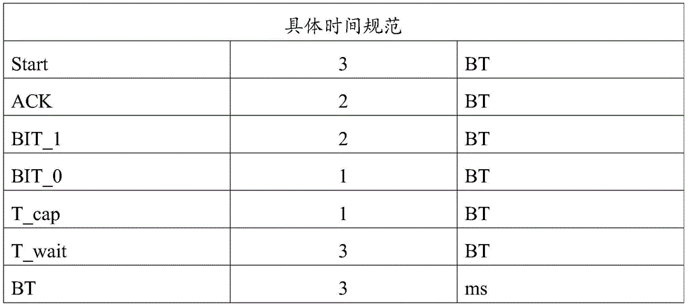
对照上表的时间规范,具体说明图4中的通信时序。首先,从第一充电协议芯片的输入输出管脚被拉成低电平的时刻开始,持续9ms的低电平,对应通信时序中的Start,用于通信测试;之后,变为高电平3msT_cap;然后,变为低电平,且持续6ms,对应通信时序中的ACK,该ACK为对第二充电协议芯片的输入输出管脚进行反馈的,表明第一充电协议芯片与第二充电协议芯片能够正常通信;再然后,变为高电平9msT_wait;之后,进入正式信息传输。Referring to the time specification in the above table, specifically explain the communication sequence in Figure 4. First, from the moment when the input and output pins of the first charging protocol chip are pulled to low level, the low level lasts for 9ms, corresponding to the Start in the communication sequence, and is used for communication testing; after that, it becomes high level for 3msT_cap ; Then, it becomes low level and lasts for 6ms, corresponding to the ACK in the communication sequence, which is for feeding back the input and output pins of the second charging protocol chip, indicating that the first charging protocol chip and the second charging protocol chip It can communicate normally; then, it becomes high level 9msT_wait; after that, it enters the formal information transmission.
即变为高电平9msT_wait之后,通过电平状态以及对应电平状态的持续时间传输通信命令,再然后变为高电平9msT_wait,之后,通过电平状态以及对应电平状态的持续时间传输该通信命令对应的通信数据。That is, after becoming high level 9msT_wait, transmit the communication command through the level state and the duration of the corresponding level state, and then become high level 9msT_wait, after that, transmit the communication command through the level state and the duration of the corresponding level state The communication data corresponding to the communication command.
在一示例中,如图4所示,变为高电平9msT_wait之后,变为3ms低电平、高电平3msT_cap和低电平3ms,说明通信指令为“00”,表示A口(这里对应图2中的Type-A USB接口)的功率发送指令,也就是说后面传输的通信数据为A口发送的A口端的功率。之后,变为高电平9ms T_wait之后,变为3ms低电平、高电平3ms T_cap、3ms低电平、高电平3ms T_cap、6ms低电平、高电平3ms T_cap和6ms低电平,说明通信指令为“0011”,具体参照下表2,能够得到A口端的功率为10W。In one example, as shown in Figure 4, after changing to a high level for 9msT_wait, it becomes a low level for 3ms, a high level for 3msT_cap, and a low level for 3ms, indicating that the communication command is "00", indicating that the A port (here corresponds to Type-A USB interface in Figure 2) power transmission command, that is to say, the communication data transmitted later is the power of the A port sent by the A port. After that, after becoming high level 9ms T_wait, it becomes 3ms low level, high level 3ms T_cap, 3ms low level, high level 3ms T_cap, 6ms low level, high level 3ms T_cap and 6ms low level , indicating that the communication command is "0011". Refer to the following table 2 for details, and the power of the A port can be obtained as 10W.
还有,具体的通信信息说明如下表2所示:In addition, the specific communication information description is shown in Table 2 below:
表2Table 2

3)在所述第一通信指令为通过第一充电接口获取功率的第一发送指令的情况下,确定所述第一通信数据为表征功率的数据,将对应所述第一通信数据的功率值确定为所述第一设备的第一拉载功率。3) In the case where the first communication instruction is the first sending instruction for obtaining power through the first charging interface, it is determined that the first communication data is data representing power, and the power value corresponding to the first communication data will be determined as the first load power of the first device.
本步骤中,通信信息由第一预设数量的比特位表示,比特位的取值“0”或“1”是通过低电平以及保持低电平不变的持续时间体现的。比如,3ms低电平用于表示“0”,6ms低电平用于表示“1”。In this step, the communication information is represented by a first preset number of bits, and the value "0" or "1" of the bit is reflected by the low level and the duration of keeping the low level unchanged. For example, 3ms low level is used to represent "0", and 6ms low level is used to represent "1".
另外,通信数据亦是如此,由第二预设数量的比特位表示。比特位的取值“0”或“1”通过低电平以及保持低电平不变的持续时间体现。In addition, the same is true for the communication data, which is represented by a second preset number of bits. The value "0" or "1" of a bit is reflected by the low level and the duration of keeping the low level unchanged.
众所周知,通信是一个通信双方相互交互的过程,上述实施例对应的是第二充电接口获取第一充电接口实时功率,根据获取到的实时功率,第二充电协议芯片调整第二充电接口侧的输出功率的过程。相应的,第二充电接口也可发送本侧的实时功率,告知给第一充电协议芯片,在需要功率调整时,第一充电协议芯片也可根据第二充电接口侧的功率,调整第一充电接口侧的输出功率。As we all know, communication is a process of mutual interaction between two communication parties. The above embodiment corresponds to the second charging interface obtaining the real-time power of the first charging interface. According to the obtained real-time power, the second charging protocol chip adjusts the output of the second charging interface side. power process. Correspondingly, the second charging interface can also send the real-time power of this side and inform the first charging protocol chip. When power adjustment is required, the first charging protocol chip can also adjust the first charging protocol chip according to the power of the second charging interface side. Output power on the interface side.
本申请实施例的步骤301获取所述第一设备的第一拉载功率,可包括:Step 301 of the embodiment of the present application to acquire the first load power of the first device may include:
方式二,在所述第一充电设备的第一拉载功率发生变化的情况下,所述第二充电接口接收所述第一充电接口发送的所述第一设备的第一拉载功率。Manner 2: When the first loading power of the first charging device changes, the second charging interface receives the first loading power of the first device sent by the first charging interface.
需要说明的是,在所述第一充电设备的第一拉载功率发生变化,且未达到第一时长的情况下,第一充电协议芯片会主动发送信息,即第一拉载功率,给第二充电协议芯片,便于第二充电协议芯片及时获取到第一设备的第二拉载功率。It should be noted that, when the first loading power of the first charging device changes and has not reached the first duration, the first charging protocol chip will actively send information, that is, the first loading power, to the first charging device. The second charging protocol chip facilitates the second charging protocol chip to obtain the second loading power of the first device in time.
具体的,第一充电接口主动发送第一设备的第一拉载功率至第二充电接口,可包括:Specifically, the first charging interface actively sends the first load power of the first device to the second charging interface, which may include:
将所述第一拉载功率按照预设规则进行数字化处理,得到用于表征所述第一拉载功率的第二通信数据;digitally processing the first loading power according to preset rules to obtain second communication data representing the first loading power;
这里,表征第一拉载功率的第二通信数据用若干个比特位表示。Here, the second communication data representing the first loading power is represented by several bits.
生成第二发送指令,并基于所述第二发送指令,控制所述第一输入输出管脚的电平状态为第二目标状态;generating a second sending instruction, and controlling the level state of the first input and output pins to be a second target state based on the second sending instruction;
这里,第二目标状态为低电平状态。默认情况下,第一输入输出管脚的电平状态为高电平。这里,通过第二发送指令触发第一输入输入输出管脚拉成低电平。Here, the second target state is a low level state. By default, the level state of the first input and output pin is high level. Here, the first I/O pin is triggered to be pulled to a low level by the second sending command.
根据预先设定的通信时序以及传输规则,得到携带有所述第二通信数据和第二发送指令的第二电平信息,并通过所述第一输入输出管脚输出至所述第二输入输出管脚。Obtain the second level information carrying the second communication data and the second sending instruction according to the preset communication timing and transmission rules, and output to the second input and output through the first input and output pins pins.
本步骤中,预先设定的通信时序以及传输规则已经在前述部分,即图4、表1和表2进行了说明,这里不再赘述。In this step, the preset communication sequence and transmission rules have been described in the foregoing part, ie, FIG. 4 , Table 1 and Table 2, and will not be repeated here.
这里,具体的,按照预先设定的通信时序以及传输规则,在经过Start、ACK以及高电平9msT_wait之后,将第二发送指令通过电平状态以及对应电平状态的持续时间的方式输出至第二输入输出管脚,然后,变为高电平9msT_wait,之后,将第二通信数据通过电平状态以及对应电平状态的持续时间的方式输出至第二输入输出管脚。Here, specifically, according to the preset communication timing and transmission rules, after Start, ACK, and high level 9msT_wait, the second sending command is output to the second transmission command through the level state and the duration of the corresponding level state. The two input and output pins then change to a high level for 9 msT_wait, and then output the second communication data to the second input and output pins through the level state and the duration of the corresponding level state.
为了避免第二设备无限制的对充电器进行拉载,保证充电器的正常工作,作为一可选地实现方式,在本申请实施例的方法步骤302之后,所述方法还可包括:In order to prevent the second device from unrestrictedly loading the charger and ensure the normal operation of the charger, as an optional implementation, after the
将调整后的功率通过所述第二充电接口发送至所述第二设备。Send the adjusted power to the second device through the second charging interface.
需要说明的是,为了避免充电器在对不同电子设备进行充电的过程中,自身温度过高,本申请实施例的方法还可包括:获取充电器的温度信息。It should be noted that, in order to prevent the temperature of the charger itself from being too high during the process of charging different electronic devices, the method in the embodiment of the present application may further include: acquiring temperature information of the charger.
这里,参考图2,可通过在充电器上设置第一温度采样模组和第二温度采样模组,以采集充电器的自身温度。Here, referring to FIG. 2 , a first temperature sampling module and a second temperature sampling module can be arranged on the charger to collect the temperature of the charger itself.
下面就图2,具体说明第一协议芯片和第二协议芯片通过输入输出管脚级联实现单线通信对应的几个通信场景。Referring to Fig. 2 below, several communication scenarios corresponding to single-wire communication realized by cascading input and output pins of the first protocol chip and the second protocol chip will be described in detail.
如图2所示,第一充电协议芯片与第一充电接口连接,即与A口连接;第二充电协议芯片与第二充电接口连接,即与C口连接。As shown in FIG. 2 , the first charging protocol chip is connected to the first charging interface, that is, it is connected to the A port; the second charging protocol chip is connected to the second charging interface, that is, it is connected to the C port.
场景一scene one
A口定时发送自己的功率信息给C口,例如A口发送信息3给C口,如图5所示,通信过程为:Port A regularly sends its own power information to port C, for example, port A sends
A(Start)->C(ACK)->A(Command=00)->A(Data=0x03)A(Start)->C(ACK)->A(Command=00)->A(Data=0x03)
场景二scene two
A口定时获取C口的功率信息,A口定时获得C口信息3,如图6所示,通信过程为:Port A regularly obtains the power information of port C, and port A regularly obtains
A(Start)->C(ACK)->A(Command=01)->C(Data=0x03)A(Start)->C(ACK)->A(Command=01)->C(Data=0x03)
场景三scene three
C口功率信息变化,C口主动发送信息给A口,C口发送信息3到A口,如图7所示,通信过程为:The power information of port C changes, port C actively sends information to port A, and port C sends
C(Start)->A(ACK)->C(Command=01)->C(Data=0x03)C(Start)->A(ACK)->C(Command=01)->C(Data=0x03)
场景四scene four
A口定时发送温度信息给C口,A口发送温度信息给C口,如图8所示,通信过程为:Port A regularly sends temperature information to port C, and port A sends temperature information to port C, as shown in Figure 8, the communication process is:
A(Start)->C(ACK)->A(Command=10)->A(Data=0x03)。A (Start)->C (ACK)->A (Command=10)->A (Data=0x03).
上述场景A与C口之间通信,是以A口为主接口,C口为从接口而言的。当然,也可以以C口为主接口,A口为从接口,这里不做具体限定。In the above scenario, the communication between port A and port C is based on the fact that port A is the master port and port C is the slave port. Of course, the C port can also be used as the main interface, and the A port can be used as the slave interface, which is not specifically limited here.
下面就一示例,结合图2,具体说明本申请实施例的充电控制方法的具体实现,也就是功率分配的实施步骤。An example will be used below to describe in detail the specific implementation of the charging control method according to the embodiment of the present application, that is, the implementation steps of power distribution, with reference to FIG. 2 .
首先,A口先插入手机,C口后插入手机(充电器总功率为60W,A、C口均支持快充,同时插入时,默认下提供A口的功率为30W,提供C口的功率30W)First, insert the mobile phone into the A port first, and then insert the mobile phone into the C port (the total power of the charger is 60W, both A and C ports support fast charging. When plugging in at the same time, the power provided by the A port is 30W by default, and the power provided by the C port is 30W)
S1,充电器的A口插入手机后,A口与A口端手机建立快充通信,A口提供60W的充电功率给A口端手机;S1, after the A port of the charger is inserted into the mobile phone, the A port establishes fast charging communication with the A port mobile phone, and the A port provides 60W charging power to the A port mobile phone;
S2,充电器检测到C口有手机插入,C口与C口端手机进行快充通信,识别到C口为快充手机,充电器复位A口的充电过程使A口返回初始状态;S2, the charger detects that a mobile phone is inserted into the C port, the C port communicates with the C port mobile phone for fast charging, and recognizes that the C port is a fast charging mobile phone, and the charger resets the charging process of the A port to return the A port to the initial state;
此时,充电器提供A口和C口最大功率均为30W。At this time, the charger provides a maximum power of 30W for both A port and C port.
这里,结合图2,具体的,充电器的第一充电协议芯片控制BUCK1电路不输出电压至A口的Vbus引脚,也就是复位A口的充电过程使A口返回初始状态。Here, referring to FIG. 2 , specifically, the first charging protocol chip of the charger controls the BUCK1 circuit not to output voltage to the Vbus pin of the A port, that is, resets the charging process of the A port to return the A port to the initial state.
S3,A口和C口端的手机分别进行30W的快充;此时,A口不断的发送信息给C口告知自己的功率或者不断的获取C口的实时功率;S3, the mobile phones at the A port and the C port are respectively fast charged at 30W; at this time, the A port continuously sends information to the C port to inform its own power or continuously obtains the real-time power of the C port;
S4,A、C口根据对方的拉载情况,实时调整自己的最大输出功率。S4, ports A and C adjust their maximum output power in real time according to the loading situation of the other party.
这里,对功率的动态分配进行一下说明。Here, the dynamic allocation of power will be described.
1、同时插入电子设备后,默认多口充的A、C口对外最大提供功率为30W。1. After plugging in electronic devices at the same time, the default maximum external power provided by the A and C ports of the multi-port charger is 30W.
2、A、C不断检测端口的拉载情况,例如,10分钟以上,A口检测到电子设备拉载均在最大功率的50%以内,此时A口告知C口侧的充电IC,A口输出功率富余,C口侧的充电IC获得A口的功率信息后,调整C口对外最大提供功率,并告知给C口端的电子设备进行更大功率充电。2. A and C constantly detect the loading status of the ports. For example, after more than 10 minutes, the A port detects that the electronic equipment is loaded within 50% of the maximum power. At this time, the A port informs the charging IC on the C port side, and the A port The output power is surplus. After the charging IC on the C port side obtains the power information of the A port, it adjusts the maximum external power provided by the C port, and informs the electronic device at the C port to charge with a higher power.
3、A口检测到A口端的电子设备退出快充,仅进行普通5v2A充电时,A口告知C口此时A口输出功率富余,C口侧的充电IC获得A口的功率信息后,调整C口对外最大提供功率,并告知给C口端的电子设备进行更大功率充电。3. When the A port detects that the electronic device at the A port exits the fast charge, and only carries out normal 5v2A charging, the A port informs the C port that the output power of the A port is sufficient at this time, and the charging IC on the C port side obtains the power information of the A port, and then adjusts The C port provides the maximum external power, and informs the electronic device at the C port to charge with a higher power.
需要说明的是的,待到一个快充口端的电子设备充电充满后,充电器提供满功率60W给另外一个充电接口。It should be noted that after the electronic device at one fast charging port is fully charged, the charger will provide a full power of 60W to the other charging port.
另外,在一示例中,A、C口同时进行快充时,如图2所示,A口有剩余的CC1和CC2口做温度检测,C口因为CC1与CC2要做快充协议的通信被占用了,没有多余的口进行温度检测,A口不断的传输自己的温度信息给C口,C口根据温度信息做过温保护。In addition, in an example, when ports A and C are performing fast charging at the same time, as shown in Figure 2, port A has the remaining ports CC1 and CC2 for temperature detection, and port C is blocked because CC1 and CC2 need to communicate with the fast charging protocol. Occupied, there is no extra port for temperature detection, A port continuously transmits its own temperature information to C port, C port is overheated according to the temperature protection.
本申请实施例的充电控制方法,在第一充电接口和第二充电接口分别与第一设备和第二设备连接,并进行快速充电的情况下,获取第一设备的第一拉载功率;在第一拉载功率满足预设条件的情况下,发送指令信息至所述第二充电接口,该指令信息用于指示将所述第二充电接口的输出功率调整至目标数值,如此,能够实现多口充电器功率的智能分配,提高多口充电器功率的有效利用率,提升用户的快充体验。In the charging control method of the embodiment of the present application, when the first charging interface and the second charging interface are respectively connected to the first device and the second device, and fast charging is performed, the first load power of the first device is obtained; When the first load power satisfies the preset condition, send instruction information to the second charging interface, the instruction information is used to instruct to adjust the output power of the second charging interface to the target value, so that multiple The intelligent distribution of the power of the multi-port charger improves the effective utilization of the power of the multi-port charger and improves the user's fast charging experience.
需要说明的是,本申请实施例提供的充电控制方法,执行主体可以为充电控制装置,或者该充电控制装置中的用于执行加载充电控制方法的控制模块。本申请实施例中以充电控制装置执行加载充电控制方法为例,说明本申请实施例提供的充电控制方法。It should be noted that, the charging control method provided in the embodiment of the present application may be executed by a charging control device, or a control module in the charging control device for executing the loading charging control method. In the embodiment of the present application, the charging control method provided by the embodiment of the present application is described by taking the charging control device executing the loading charging control method as an example.
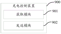
如图9所示,本申请实施例还提供了一种充电控制装置900,应用于充电器,该充电器包括至少两个充电接口和至少两个充电协议芯片,每一充电接口分别与对应的充电协议芯片连接,所述至少两个充电协议芯片之间彼此通信连接;所述装置包括:As shown in Figure 9, the embodiment of the present application also provides a charging
获取模块901,用于在第一充电接口和第二充电接口分别与第一设备和第二设备连接,并进行快速充电的情况下,获取所述第一设备的第一拉载功率;An
发送模块902,用于在所述第一拉载功率满足预设条件的情况下,发送指令信息至所述第二充电接口,所述指令信息用于指示将所述第二充电接口的输出功率调整至目标数值。The sending
可选地,所述发送模块902包括:Optionally, the sending
第一发送单元,用于在所述第一拉载功率在预设时间内持续低于第一阈值的情况下,发送第一指令信息至所述第二充电接口,所述第一指令信息用于指示调高所述第二充电接口的输出功率至第一目标值;或者,The first sending unit is configured to send first instruction information to the second charging interface when the first loading power is continuously lower than the first threshold within a preset time, and the first instruction information is used for Instructing to increase the output power of the second charging interface to the first target value; or,
第二发送单元,用于在所述第一拉载功率在单位时间内的下降量超过第二阈值情况下,发送第二指令信息至所述第二充电接口,所述第二指令信息用于指示调高所述第二充电接口的输出功率至第二目标值;或者,The second sending unit is configured to send second instruction information to the second charging interface when the decrease amount of the first load power per unit time exceeds a second threshold, and the second instruction information is used for instructing to increase the output power of the second charging interface to a second target value; or,
第三发送单元,用于在所述第一拉载功率大于第一输出功率的情况下,发送第三指令信息至所述第二充电接口,所述第三指令信息用于指示降低所述第二充电接口的输出功率至第三目标值。A third sending unit, configured to send third instruction information to the second charging interface when the first load power is greater than the first output power, and the third instruction information is used to instruct to reduce the first output power. The output power of the second charging interface reaches the third target value.
可选地,所述第二充电接口为主接口,所述第一充电接口为从接口;所述获取模块901具体用于:Optionally, the second charging interface is a master interface, and the first charging interface is a slave interface; the obtaining
所述第二充电接口每隔第一时长获取所述第一设备的第一拉载功率;或者,The second charging interface acquires the first loading power of the first device every first time period; or,
在所述第一充电设备的第一拉载功率发生变化的情况下,所述第二充电接口接收所述第一充电接口发送的所述第一设备的第一拉载功率。When the first loading power of the first charging device changes, the second charging interface receives the first loading power of the first device sent by the first charging interface.
本申请实施例中的充电控制装置可以是装置,也可以是终端中的部件、集成电路、或芯片。该装置可以是移动电子设备,也可以为非移动电子设备。示例性的,示例性的,移动电子设备可以为手机、平板电脑、笔记本电脑、掌上电脑、车载电子设备、可穿戴设备、超级移动个人计算机(ultra-mobile personal computer,UMPC)、上网本或者个人数字助理(personal digital assistant,PDA)等,非移动电子设备可以为网络附属存储器(NetworkAttached Storage,NAS)、个人计算机(personal computer,PC)、电视机(television,TV)、柜员机或者自助机等,本申请实施例不作具体限定。The charging control device in the embodiment of the present application may be a device, or a component, an integrated circuit, or a chip in a terminal. The device may be a mobile electronic device or a non-mobile electronic device. Exemplary, exemplary, the mobile electronic device may be a mobile phone, a tablet computer, a notebook computer, a palmtop computer, a vehicle electronic device, a wearable device, an ultra-mobile personal computer (ultra-mobile personal computer, UMPC), a netbook or a personal digital Assistant (personal digital assistant, PDA), etc., non-mobile electronic devices can be network attached storage (NetworkAttached Storage, NAS), personal computer (personal computer, PC), television (television, TV), teller machine or self-service machine, etc., this The application examples are not specifically limited.
本申请实施例中的充电控制装置可以为具有操作系统的装置。该操作系统可以为安卓(Android)操作系统,可以为ios操作系统,还可以为其他可能的操作系统,本申请实施例不作具体限定。The charging control device in the embodiment of the present application may be a device with an operating system. The operating system may be an Android (Android) operating system, an ios operating system, or other possible operating systems, which are not specifically limited in this embodiment of the present application.
本申请实施例提供的充电控制装置能够实现图1至图8的方法实施例实现的各个过程,为避免重复,这里不再赘述。The charging control device provided in the embodiment of the present application can realize various processes realized by the method embodiments in FIG. 1 to FIG. 8 , and details are not repeated here to avoid repetition.
本申请实施例的充电控制装置,通过获取模块在第一充电接口和第二充电接口分别与第一设备和第二设备连接,并进行快速充电的情况下,获取第一设备的第一拉载功率;发送模块在第一拉载功率满足预设条件的情况下,发送指令信息至所述第二充电接口,该指令信息用于指示将所述第二充电接口的输出功率调整至目标数值,如此,能够实现多口充电器功率的智能分配,提高多口充电器功率的有效利用率,提升用户的快充体验。In the charging control device according to the embodiment of the present application, the acquisition module acquires the first load of the first device when the first charging interface and the second charging interface are respectively connected to the first device and the second device and fast charging is performed. power; the sending module sends instruction information to the second charging interface when the first loading power satisfies the preset condition, and the instruction information is used to instruct to adjust the output power of the second charging interface to a target value, In this way, it is possible to realize the intelligent distribution of the power of the multi-port charger, improve the effective utilization rate of the power of the multi-port charger, and improve the user's fast charging experience.
可选地,本申请实施例还提供一种充电器,包括如上述实施例所述的充电控制装置。Optionally, an embodiment of the present application further provides a charger, including the charging control device as described in the foregoing embodiments.
可选地,本申请实施例还提供一种充电器,包括处理器,存储器,存储在存储器上并可在所述处理器上运行的程序或指令,该程序或指令被处理器执行时实现上述充电控制方法实施例的各个过程,且能达到相同的技术效果,为避免重复,这里不再赘述。Optionally, an embodiment of the present application further provides a charger, including a processor, a memory, and a program or instruction stored in the memory and operable on the processor. When the program or instruction is executed by the processor, the above-mentioned The various processes of the embodiment of the charging control method can achieve the same technical effect, so in order to avoid repetition, details are not repeated here.
需要注意的是,本申请实施例中的充电器包括上述所述的移动电子设备和非移动电子设备。It should be noted that the chargers in the embodiments of the present application include the above-mentioned mobile electronic devices and non-mobile electronic devices.
本申请实施例还提供一种可读存储介质,所述可读存储介质上存储有程序或指令,该程序或指令被处理器执行时实现上述充电控制方法实施例的各个过程,且能达到相同的技术效果,为避免重复,这里不再赘述。The embodiment of the present application also provides a readable storage medium. The readable storage medium stores programs or instructions. When the program or instructions are executed by the processor, the various processes of the above charging control method embodiments can be achieved, and the same To avoid repetition, the technical effects will not be repeated here.
其中,所述处理器为上述实施例中所述的充电器中的处理器。所述可读存储介质,包括计算机可读存储介质,如计算机只读存储器(Read-Only Memory,ROM)、随机存取存储器(Random Access Memory,RAM)、磁碟或者光盘等。Wherein, the processor is the processor in the charger described in the above embodiment. The readable storage medium includes a computer readable storage medium, such as a computer read-only memory (Read-Only Memory, ROM), a random access memory (Random Access Memory, RAM), a magnetic disk or an optical disk, and the like.
本申请实施例另提供了一种芯片,所述芯片包括处理器和通信接口,所述通信接口和所述处理器耦合,所述处理器用于运行程序或指令,实现上述充电控制方法实施例的各个过程,且能达到相同的技术效果,为避免重复,这里不再赘述。The embodiment of the present application further provides a chip, the chip includes a processor and a communication interface, the communication interface is coupled to the processor, and the processor is used to run programs or instructions to implement the above charging control method embodiment Each process can achieve the same technical effect, so in order to avoid repetition, it will not be repeated here.
应理解,本申请实施例提到的芯片还可以称为系统级芯片、系统芯片、芯片系统或片上系统芯片等。It should be understood that the chips mentioned in the embodiments of the present application may also be called system-on-chip, system-on-chip, system-on-a-chip, or system-on-a-chip.
需要说明的是,在本文中,术语“包括”、“包含”或者其任何其他变体意在涵盖非排他性的包含,从而使得包括一系列要素的过程、方法、物品或者装置不仅包括那些要素,而且还包括没有明确列出的其他要素,或者是还包括为这种过程、方法、物品或者装置所固有的要素。在没有更多限制的情况下,由语句“包括一个……”限定的要素,并不排除在包括该要素的过程、方法、物品或者装置中还存在另外的相同要素。此外,需要指出的是,本申请实施方式中的方法和装置的范围不限按示出或讨论的顺序来执行功能,还可包括根据所涉及的功能按基本同时的方式或按相反的顺序来执行功能,例如,可以按不同于所描述的次序来执行所描述的方法,并且还可以添加、省去、或组合各种步骤。另外,参照某些示例所描述的特征可在其他示例中被组合。It should be noted that, in this document, the term "comprising", "comprising" or any other variation thereof is intended to cover a non-exclusive inclusion such that a process, method, article or apparatus comprising a set of elements includes not only those elements, It also includes other elements not expressly listed, or elements inherent in the process, method, article, or device. Without further limitations, an element defined by the phrase "comprising a ..." does not preclude the presence of additional identical elements in the process, method, article, or apparatus comprising that element. In addition, it should be pointed out that the scope of the methods and devices in the embodiments of the present application is not limited to performing functions in the order shown or discussed, and may also include performing functions in a substantially simultaneous manner or in reverse order according to the functions involved. Functions are performed, for example, the described methods may be performed in an order different from that described, and various steps may also be added, omitted, or combined. Additionally, features described with reference to certain examples may be combined in other examples.
通过以上的实施方式的描述,本领域的技术人员可以清楚地了解到上述实施例方法可借助软件加必需的通用硬件平台的方式来实现,当然也可以通过硬件,但很多情况下前者是更佳的实施方式。基于这样的理解,本申请的技术方案本质上或者说对现有技术做出贡献的部分可以以软件产品的形式体现出来,该计算机软件产品存储在一个存储介质(如ROM/RAM、磁碟、光盘)中,包括若干指令用以使得一台终端(可以是手机,计算机,服务器,空调器,或者网络设备等)执行本申请各个实施例所述的方法。Through the description of the above embodiments, those skilled in the art can clearly understand that the methods of the above embodiments can be implemented by means of software plus a necessary general-purpose hardware platform, and of course also by hardware, but in many cases the former is better implementation. Based on such an understanding, the technical solution of the present application can be embodied in the form of a software product in essence or the part that contributes to the prior art, and the computer software product is stored in a storage medium (such as ROM/RAM, disk, CD) contains several instructions to enable a terminal (which may be a mobile phone, a computer, a server, an air conditioner, or a network device, etc.) to execute the methods described in various embodiments of the present application.
以上所述是本发明的优选实施方式,应当指出,对于本技术领域的普通技术人员来说,在不脱离本发明所述原理的前提下,还可以作出若干改进和润饰,这些改进和润饰也应视为本发明的保护范围。The above description is a preferred embodiment of the present invention, it should be pointed out that for those of ordinary skill in the art, without departing from the principle of the present invention, some improvements and modifications can also be made, and these improvements and modifications can also be made. It should be regarded as the protection scope of the present invention.
Claims (12)
Priority Applications (2)
| Application Number | Priority Date | Filing Date | Title |
|---|---|---|---|
| CN202011049947.3A CN112202222B (en) | 2020-09-29 | 2020-09-29 | Charger, charging control method and device |
| PCT/CN2021/121256 WO2022068802A1 (en) | 2020-09-29 | 2021-09-28 | Charger, and charging control method and apparatus |
Applications Claiming Priority (1)
| Application Number | Priority Date | Filing Date | Title |
|---|---|---|---|
| CN202011049947.3A CN112202222B (en) | 2020-09-29 | 2020-09-29 | Charger, charging control method and device |
Publications (2)
| Publication Number | Publication Date |
|---|---|
| CN112202222A CN112202222A (en) | 2021-01-08 |
| CN112202222B true CN112202222B (en) | 2023-03-14 |
Family
ID=74008451
Family Applications (1)
| Application Number | Title | Priority Date | Filing Date |
|---|---|---|---|
| CN202011049947.3A Active CN112202222B (en) | 2020-09-29 | 2020-09-29 | Charger, charging control method and device |
Country Status (2)
| Country | Link |
|---|---|
| CN (1) | CN112202222B (en) |
| WO (1) | WO2022068802A1 (en) |
Families Citing this family (25)
| Publication number | Priority date | Publication date | Assignee | Title |
|---|---|---|---|---|
| CN112202222B (en) * | 2020-09-29 | 2023-03-14 | 维沃移动通信有限公司 | Charger, charging control method and device |
| CN112886656B (en) * | 2021-01-15 | 2024-06-11 | 维沃移动通信有限公司 | Converters and charging systems |
| CN112910038A (en) * | 2021-01-22 | 2021-06-04 | 维沃移动通信有限公司 | Power conversion device and method and electronic equipment |
| CN113193620B (en) * | 2021-04-26 | 2024-05-17 | 维沃移动通信有限公司 | Charging power adjustment method and device and electronic equipment |
| CN115514033B (en) * | 2021-06-22 | 2025-11-18 | 安克创新科技股份有限公司 | Charging methods, power supply equipment, and computer-readable storage media |
| CN113410886B (en) * | 2021-06-23 | 2025-01-28 | 深圳传音控股股份有限公司 | A charging control method, mobile terminal and storage medium |
| CN114069768B (en) * | 2021-09-17 | 2023-03-24 | 荣耀终端有限公司 | Charging circuit, charging control method and device and electronic equipment |
| CN114123380A (en) * | 2021-10-15 | 2022-03-01 | 华为数字能源技术有限公司 | Charging device, charger, and charging power adjustment method |
| CN114094662B (en) * | 2021-11-18 | 2024-04-23 | 闪极科技(深圳)有限公司 | Intelligent power allocation method for multi-port fast charger |
| CN114696417A (en) * | 2022-04-01 | 2022-07-01 | 北京小米移动软件有限公司 | Charging conversion device, charging method and device, electronic device, and storage medium |
| CN116031964B (en) * | 2022-05-30 | 2023-12-22 | 荣耀终端有限公司 | Charging control method and terminal equipment |
| CN115032919B (en) * | 2022-06-30 | 2025-08-19 | 无锡睿勤科技有限公司 | Charging test method and test system |
| CN116031965B (en) * | 2022-06-30 | 2023-10-27 | 荣耀终端有限公司 | Charging method, device, power adapter and storage medium |
| CN115224770B (en) * | 2022-08-11 | 2024-03-22 | 绍兴光大芯业微电子有限公司 | PD super-fast charge SOC system for realizing multi-power multi-configuration full time domain |
| CN115802241A (en) * | 2022-11-29 | 2023-03-14 | 珠海美佳音科技有限公司 | Switching and shunting method, device, equipment and storage medium |
| CN116207817A (en) * | 2023-01-12 | 2023-06-02 | 维沃移动通信有限公司 | Charging method, charging device, electronic equipment and readable storage medium |
| CN116169758B (en) * | 2023-04-25 | 2024-05-03 | 厦门英麦科芯集成科技有限公司 | Output power adjusting method and charger |
| CN116418093B (en) * | 2023-06-07 | 2023-10-24 | 厦门英麦科芯集成科技有限公司 | Charger and bidirectional communication method thereof |
| CN116418094B (en) * | 2023-06-07 | 2023-09-22 | 厦门英麦科芯集成科技有限公司 | Charger and single bus communication method of charger |
| CN116505628B (en) * | 2023-06-28 | 2024-01-19 | 深圳市澳博森科技有限公司 | Intelligent multi-port adapter charging control method and system |
| CN119275955A (en) * | 2023-07-07 | 2025-01-07 | 安克创新科技股份有限公司 | Charger and power distribution method of charger |
| CN116937751B (en) * | 2023-09-13 | 2023-12-22 | 深圳市金致卓科技有限公司 | Circuit compatible with multiple protocols for charger and control method |
| CN120834617A (en) * | 2024-04-23 | 2025-10-24 | 安克创新科技股份有限公司 | Data transmission method and data transmission device |
| CN118868334B (en) * | 2024-09-04 | 2025-02-28 | 宁波从越科技创新有限公司 | Portable energy storage device capable of simultaneously charging and discharging multiple ports and charging and discharging power distribution method |
| CN119881400A (en) * | 2025-03-26 | 2025-04-25 | 沐曦科技(北京)有限公司 | Pull-load test circuit and device |
Citations (4)
| Publication number | Priority date | Publication date | Assignee | Title |
|---|---|---|---|---|
| CN108649676A (en) * | 2018-06-15 | 2018-10-12 | 上海脱颖网络科技有限公司 | A kind of the fast charge power supply and its application method of adjust automatically and distribution power |
| CN110138048A (en) * | 2019-06-10 | 2019-08-16 | 宁波科曼电子科技有限公司 | It is a kind of can automatic distribution power power supply and its application method |
| CN210898617U (en) * | 2019-12-31 | 2020-06-30 | 无锡速芯微电子有限公司 | Double-port quick charger |
| CN111628537A (en) * | 2020-04-24 | 2020-09-04 | 杭州士兰微电子股份有限公司 | Multi-channel charging circuit and its protocol control module and control method |
Family Cites Families (10)
| Publication number | Priority date | Publication date | Assignee | Title |
|---|---|---|---|---|
| US20140049209A1 (en) * | 2012-08-16 | 2014-02-20 | Chin-Ching Chang | Charging converter |
| CN205882808U (en) * | 2016-07-01 | 2017-01-11 | Tcl通力电子(惠州)有限公司 | Multiport power supply output circuit and battery charging outfit |
| CN107706972A (en) * | 2017-09-30 | 2018-02-16 | 湖南海翼电子商务股份有限公司 | Power output control method, circuit and charging device for charging device |
| CN209088592U (en) * | 2018-12-26 | 2019-07-09 | 深圳曜佳信息技术有限公司 | A kind of fast charge circuit of two-way DC reduced output voltage PD intelligent power distribution |
| US11791650B2 (en) * | 2019-03-18 | 2023-10-17 | Texas Instruments Incorporated | Multiple output charging system and controller |
| CN210092932U (en) * | 2019-08-02 | 2020-02-18 | 深圳市福佳电器有限公司 | Combined charger with TYPE A and TYPE C interfaces |
| CN110380489A (en) * | 2019-08-08 | 2019-10-25 | 珠海英集芯半导体有限公司 | A kind of fast charge circuit that can automatically adjust power and method |
| CN211296285U (en) * | 2019-11-22 | 2020-08-18 | 湖南炬神电子有限公司 | Multi-port PD output charger |
| CN111313515A (en) * | 2020-04-20 | 2020-06-19 | 深圳英集芯科技有限公司 | Multi-output-port fast charging switching circuit and method |
| CN112202222B (en) * | 2020-09-29 | 2023-03-14 | 维沃移动通信有限公司 | Charger, charging control method and device |
-
2020
- 2020-09-29 CN CN202011049947.3A patent/CN112202222B/en active Active
-
2021
- 2021-09-28 WO PCT/CN2021/121256 patent/WO2022068802A1/en not_active Ceased
Patent Citations (4)
| Publication number | Priority date | Publication date | Assignee | Title |
|---|---|---|---|---|
| CN108649676A (en) * | 2018-06-15 | 2018-10-12 | 上海脱颖网络科技有限公司 | A kind of the fast charge power supply and its application method of adjust automatically and distribution power |
| CN110138048A (en) * | 2019-06-10 | 2019-08-16 | 宁波科曼电子科技有限公司 | It is a kind of can automatic distribution power power supply and its application method |
| CN210898617U (en) * | 2019-12-31 | 2020-06-30 | 无锡速芯微电子有限公司 | Double-port quick charger |
| CN111628537A (en) * | 2020-04-24 | 2020-09-04 | 杭州士兰微电子股份有限公司 | Multi-channel charging circuit and its protocol control module and control method |
Also Published As
| Publication number | Publication date |
|---|---|
| WO2022068802A1 (en) | 2022-04-07 |
| CN112202222A (en) | 2021-01-08 |
Similar Documents
| Publication | Publication Date | Title |
|---|---|---|
| CN112202222B (en) | Charger, charging control method and device | |
| EP3131171B1 (en) | Power adaptor, terminal and charging system | |
| CN107947252B (en) | Terminal and equipment | |
| JP6452162B2 (en) | Charging method, mobile device, and charging system | |
| CN108988431B (en) | Multi-protocol charging device and multi-protocol charging method | |
| CN110854939B (en) | Method for charging double batteries, electronic device and storage medium | |
| CN107834628B (en) | Circuit and method for realizing multiple fast charging protocols based on TYPE-C interface | |
| CN101593990A (en) | Realize method, device and the integrated circuit of the intellectual power management of USB port | |
| CN112540304B (en) | Battery power management method, electronic device and computer storage medium | |
| WO2023000814A1 (en) | Power adapter and charging control method | |
| CN108123515A (en) | Chargeable electronic equipment | |
| CN117674359A (en) | A dynamic power allocation method, system and computer-readable storage medium for a multi-port charger | |
| CN106786843A (en) | The method of adjustment and system of a kind of charging current, electric terminal | |
| CN116231787A (en) | A charging and discharging control method, device, terminal equipment and storage medium | |
| CN104600830A (en) | Current sharing method and system of power supply module and manager | |
| CN107959317A (en) | A kind of charging method and its device | |
| CN110086229A (en) | A kind of charging method, device, terminal device and computer readable storage medium | |
| CN107437828B (en) | Charging method, device and equipment | |
| CN113672067B (en) | Thunderbolt docking station and configuration device | |
| US10742057B2 (en) | Self-loop detection method and apparatus for charging device | |
| CN116169758B (en) | Output power adjusting method and charger | |
| WO2025030848A1 (en) | Charging method and terminal device | |
| CN213754344U (en) | Adapter output expansion device | |
| CN106685003A (en) | Charging device based on low voltage direct charge, charging system and charging control method | |
| CN112653213A (en) | Charging control method and device |
Legal Events
| Date | Code | Title | Description |
|---|---|---|---|
| PB01 | Publication | ||
| PB01 | Publication | ||
| SE01 | Entry into force of request for substantive examination | ||
| SE01 | Entry into force of request for substantive examination | ||
| GR01 | Patent grant | ||
| GR01 | Patent grant |