CN112189955B - Wearable device and control method and control device thereof - Google Patents
Wearable device and control method and control device thereof Download PDFInfo
- Publication number
- CN112189955B CN112189955B CN202010991892.1A CN202010991892A CN112189955B CN 112189955 B CN112189955 B CN 112189955B CN 202010991892 A CN202010991892 A CN 202010991892A CN 112189955 B CN112189955 B CN 112189955B
- Authority
- CN
- China
- Prior art keywords
- main body
- module
- detachable module
- battery
- wearable device
- Prior art date
- Legal status (The legal status is an assumption and is not a legal conclusion. Google has not performed a legal analysis and makes no representation as to the accuracy of the status listed.)
- Active
Links
Images


Classifications
-
- A—HUMAN NECESSITIES
- A44—HABERDASHERY; JEWELLERY
- A44C—PERSONAL ADORNMENTS, e.g. JEWELLERY; COINS
- A44C5/00—Bracelets; Wrist-watch straps; Fastenings for bracelets or wrist-watch straps
- A44C5/14—Bracelets; Wrist-watch straps; Fastenings for bracelets or wrist-watch straps characterised by the way of fastening to a wrist-watch or the like
-
- A—HUMAN NECESSITIES
- A44—HABERDASHERY; JEWELLERY
- A44C—PERSONAL ADORNMENTS, e.g. JEWELLERY; COINS
- A44C5/00—Bracelets; Wrist-watch straps; Fastenings for bracelets or wrist-watch straps
- A44C5/0007—Bracelets specially adapted for other functions or with means for attaching other articles
-
- Y—GENERAL TAGGING OF NEW TECHNOLOGICAL DEVELOPMENTS; GENERAL TAGGING OF CROSS-SECTIONAL TECHNOLOGIES SPANNING OVER SEVERAL SECTIONS OF THE IPC; TECHNICAL SUBJECTS COVERED BY FORMER USPC CROSS-REFERENCE ART COLLECTIONS [XRACs] AND DIGESTS
- Y02—TECHNOLOGIES OR APPLICATIONS FOR MITIGATION OR ADAPTATION AGAINST CLIMATE CHANGE
- Y02E—REDUCTION OF GREENHOUSE GAS [GHG] EMISSIONS, RELATED TO ENERGY GENERATION, TRANSMISSION OR DISTRIBUTION
- Y02E60/00—Enabling technologies; Technologies with a potential or indirect contribution to GHG emissions mitigation
- Y02E60/10—Energy storage using batteries
Landscapes
- Battery Mounting, Suspending (AREA)
Abstract
本申请公开一种可穿戴设备,包括主体部、连接带和可拆分模组,连接带与主体部相连,主体部包括功能模组和第一电池,可拆分模组与主体部可拆卸相连,可拆分模组包括第二电池;主体部和可拆分模组中,一者设置有可移动的操作部,另一者设置有插接孔,操作部包括操作按钮和与操作按钮相连的插接杆,插接杆可随操作按钮在第一位置与第二位置之间移动,在插接杆处于第一位置的情况下,可拆分模组与主体部通过插接杆与插接孔的插接配合装配相连,且第二电池与功能模组电连接;在插接杆处于第二位置的情况下,插接杆与插接孔分离,且第一电池与功能模组电连接。上述方案能够解决目前的可穿戴设备存在无法较长时间进行持续工作的问题。
The application discloses a wearable device, which includes a main body, a connecting belt and a detachable module, the connecting belt is connected to the main body, the main body includes a functional module and a first battery, and the detachable module is detachable from the main body connected, the detachable module includes a second battery; among the main body and the detachable module, one is provided with a movable operation part, and the other is provided with a socket hole, and the operation part includes an operation button and an operation button The connecting rod can move between the first position and the second position with the operation button. When the connecting rod is in the first position, the detachable module and the main body can be connected by the connecting rod. The plug-in fitting assembly of the socket hole is connected, and the second battery is electrically connected to the functional module; when the plug-in rod is in the second position, the plug-in rod is separated from the socket hole, and the first battery is connected to the functional module electrical connection. The above solution can solve the problem that the current wearable device cannot continue to work for a long time.
Description
技术领域technical field
本申请涉及通信设备技术领域,尤其涉及一种可穿戴设备及其控制方法和控制装置。The present application relates to the technical field of communication equipment, and in particular to a wearable equipment and its control method and control device.
背景技术Background technique
随着5G技术的成熟,我们正在进入一个“万物互联”的时代,无论是醒着还是睡着,我们都可以与这个世界保持不间断的联系。可穿戴设备就是一种人与世界互联的重要手段,它在人们的生活中扮演着重要的角色。例如,可穿戴设备可以帮助用户记录日常生活中的锻炼、睡眠、饮食等数据,通过数据可以了解自己是否健康生活。With the maturity of 5G technology, we are entering an era of "Internet of Everything", where we can maintain an uninterrupted connection with the world whether we are awake or asleep. Wearable devices are an important means of connecting people and the world, and they play an important role in people's lives. For example, wearable devices can help users record exercise, sleep, diet and other data in daily life, and through the data, they can know whether they are living a healthy life.
目前的可穿戴设备的续航能力有限,难以满足较长时间工作的需求。在可穿戴设备的电量较低的情况下,用户必须摘下可穿戴设备进行充电,进而导致可穿戴设备的功能模组检测中断。可见,目前的可穿戴设备存在无法较长时间进行持续工作的问题。The current wearable devices have limited battery life, and it is difficult to meet the needs of working for a long time. When the power of the wearable device is low, the user has to take off the wearable device to charge it, which causes the detection of the functional modules of the wearable device to be interrupted. It can be seen that the current wearable devices have the problem that they cannot continue to work for a long time.
发明内容Contents of the invention
本申请公开一种可穿戴设备,以解决目前的可穿戴设备存在无法较长时间进行持续工作的问题。The present application discloses a wearable device to solve the problem that the current wearable device cannot work continuously for a long time.
为解决上述问题,本申请采用下述技术方案:In order to solve the above problems, the application adopts the following technical solutions:
第一方面,本申请公开一种可穿戴设备,包括主体部、连接带和可拆分模组,连接带与主体部相连,主体部包括功能模组和第一电池,可拆分模组与主体部可拆卸相连,可拆分模组包括第二电池;主体部和可拆分模组中,一者设置有可移动的操作部,另一者设置有插接孔,操作部包括操作按钮和与操作按钮相连的插接杆,插接杆可随操作按钮在第一位置与第二位置之间移动,在插接杆处于第一位置的情况下,可拆分模组与主体部通过插接杆与插接孔的插接配合相连;在插接杆处于第二位置的情况下,插接杆与插接孔分离,且可拆分模组与主体部可分离;在可拆分模组与主体部相连的情况下,第二电池与功能模组电连接;在可拆分模组与主体部分离的情况下,第一电池与功能模组电连接。In the first aspect, the present application discloses a wearable device, which includes a main body, a connection belt and a detachable module, the connection belt is connected to the main body, the main body includes a functional module and a first battery, and the detachable module is connected to the first battery. The main body is detachably connected, and the detachable module includes a second battery; one of the main body and the detachable module is provided with a movable operation part, and the other is provided with an insertion hole, and the operation part includes an operation button and the insertion rod connected with the operation button, the insertion rod can move between the first position and the second position with the operation button, when the insertion rod is in the first position, the detachable module and the main body can pass through The insertion rod is connected with the insertion hole; when the insertion rod is in the second position, the insertion rod is separated from the insertion hole, and the detachable module can be separated from the main body; When the module is connected to the main body, the second battery is electrically connected to the functional module; when the detachable module is separated from the main body, the first battery is electrically connected to the functional module.
第二方面,本申请公开一种可穿戴设备的控制方法,所涉及的可穿戴设备为上文所述的可穿戴设备,所公开的控制方法包括:In the second aspect, the present application discloses a control method of a wearable device, the wearable device involved is the above-mentioned wearable device, and the disclosed control method includes:
获取可拆分模组的状态;Obtain the status of the detachable module;
在可拆分模组为拆卸状态的情况下,控制第一电池与功能模组切换至供电连接状态;When the detachable module is in the disassembled state, controlling the first battery and the functional module to switch to the power supply connection state;
在可拆分模组为装配状态的情况下,控制第二电池与功能模组切换至供电连接状态以及控制第一电池与功能模组之间的电连接断开。When the detachable module is in an assembled state, control the second battery and the functional module to switch to a power supply connection state and control the electrical connection between the first battery and the functional module to disconnect.
第三方面,本申请公开一种可穿戴设备的控制装置,所涉及的可穿戴设备为上文所述的可穿戴设备,所述控制装置包括:In a third aspect, the present application discloses a control device for a wearable device, the wearable device involved is the above-mentioned wearable device, and the control device includes:
获取模块,用于获取可拆分模组的状态;Get the module, used to get the status of the detachable module;
第一控制模块,用于在可拆分模组为拆卸状态的情况下,控制第一电池与功能模组切换至供电连接状态;The first control module is used to control the first battery and the functional module to switch to the power supply connection state when the detachable module is in the disassembled state;
第二控制模块,用于在可拆分模组为装配状态的情况下,控制第二电池与功能模组切换至供电连接状态以及控制第一电池与功能模组之间的电连接断开。The second control module is used for controlling the switching of the second battery and the functional module to a power supply connection state and controlling the disconnection of the electrical connection between the first battery and the functional module when the detachable module is in an assembled state.
本申请采用的技术方案能够达到以下有益效果:The technical solution adopted in this application can achieve the following beneficial effects:
本申请公开的可穿戴设备中,可拆分模组通过插接杆和插接孔的配合,从而实现与主体部之间的可拆卸相连,通过调整插接杆在第一位置与第二位置之间的切换,能够实现可拆分模组的拆装,可拆分模组包括第二电池,在可拆分模组与主体部相连的情况下,且第二电池与功能模组电连接,从而使得功能模组能够运行;在可拆分模组与主体部分离的情况下,分离后的可拆分模组能够去充电以补充电能,第一电池与功能模组电连接,从而使得功能模组能够继续运行,进而使得可穿戴设备能够进行较长时间的持续工作。In the wearable device disclosed in this application, the detachable module can be detachably connected to the main body through the cooperation of the insertion rod and the insertion hole. By adjusting the insertion rod between the first position and the second position The switch between can realize the disassembly and assembly of the detachable module. The detachable module includes a second battery. When the detachable module is connected to the main body, and the second battery is electrically connected to the functional module , so that the functional module can run; when the detachable module is separated from the main body, the separated detachable module can be charged to supplement electric energy, and the first battery is electrically connected to the functional module, so that The functional modules can continue to operate, thereby enabling the wearable device to perform continuous work for a longer period of time.
附图说明Description of drawings
为了更清楚地说明本申请实施例或背景技术中的技术方案,下面将对实施例或背景技术描述中所需要使用的附图作简单的介绍,显而易见地,对于本领域普通技术人员而言,在不付出创造性劳动性的前提下,还可以根据这些附图获得其他的附图。In order to more clearly illustrate the technical solutions in the embodiments of the present application or the background technology, the following will briefly introduce the drawings that need to be used in the description of the embodiments or the background technology. Obviously, for those of ordinary skill in the art, Other drawings can also be obtained from these drawings without any creative effort.
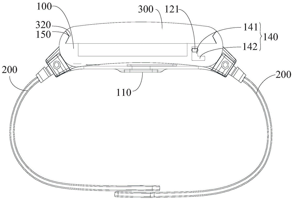
图1为本申请实施例公开的可穿戴设备的在一视角下的结构示意图;FIG. 1 is a schematic structural diagram of a wearable device disclosed in an embodiment of the present application under a viewing angle;
图2为本申请实施例公开的可穿戴设备的在另一视角下的结构示意图;Fig. 2 is a schematic structural diagram of a wearable device disclosed in an embodiment of the present application under another viewing angle;
图3为本申请实施例公开的可穿戴设备的爆炸结构示意图;FIG. 3 is a schematic diagram of an exploded structure of a wearable device disclosed in an embodiment of the present application;
图4为本申请实施例公开的可穿戴设备的又一视角下的结构示意图;Fig. 4 is a structural schematic diagram of another perspective of the wearable device disclosed in the embodiment of the present application;
图5为本申请实施例公开的操作部的结构示意图。Fig. 5 is a schematic structural diagram of the operating unit disclosed in the embodiment of the present application.
附图标记说明:Explanation of reference signs:
100-主体部、110-功能模组、120-操作部、121-操作按钮、121a-凸点、122-插接杆、123-弹性件、130-容纳槽、140-穿孔、141-第一段、142-第二段、150-限位凸起、160-扭簧、170-第一限位凸部;100-Main part, 110-Functional module, 120-Operation part, 121-Operation button, 121a-Bump, 122-Insertion rod, 123-Elastic piece, 130-Accommodating groove, 140-Pierce, 141-First Section, 142-the second section, 150-limiting protrusion, 160-torsion spring, 170-the first limiting protrusion;
200-连接带;200 - connection belt;
300-可拆分模组、310-插接孔、320-限位凹陷、330-第二限位凸部。300-detachable module, 310-socket hole, 320-limiting depression, 330-second limiting protrusion.
具体实施方式Detailed ways
为使本申请的目的、技术方案和优点更加清楚,下面将结合本申请具体实施例及相应的附图对本申请技术方案进行清楚、完整地描述。显然,所描述的实施例仅是本申请的一部分实施例,而不是全部的实施例。基于本申请中的实施例,本领域普通技术人员在没有做出创造性劳动前提下所获得的所有其他实施例,都属于本申请保护的范围。In order to make the purpose, technical solution and advantages of the present application clearer, the technical solution of the present application will be clearly and completely described below in conjunction with specific embodiments of the present application and corresponding drawings. Apparently, the described embodiments are only some of the embodiments of this application, not all of them. Based on the embodiments in this application, all other embodiments obtained by persons of ordinary skill in the art without making creative efforts belong to the scope of protection of this application.
以下结合附图,详细说明本申请各个实施例公开的技术方案。The technical solutions disclosed in various embodiments of the present application will be described in detail below with reference to the accompanying drawings.
请参考图1至图5,本申请实施例公开一种可穿戴设备,所公开的可穿戴设备包括主体部100、连接带200和可拆分模组300。Please refer to FIG. 1 to FIG. 5 , the embodiment of the present application discloses a wearable device, and the disclosed wearable device includes a
主体部100为连接带200和可拆分模组300的安装基础,具体地,连接带200与主体部100相连,连接带200可以通过粘接、螺纹连接件连接等方式实现与主体部100相连,对此本申请实施例不作限制,主体部100包括功能模组110和第一电池,功能模组110可以是传感器、检测器等功能性检测元件,对此本申请实施例也不作限制。The
可拆分模组300为所述可穿戴设备的功能性器件,可拆分模组可以包括显示屏,显示屏可以显示当前的用户的检测参数、当前时间等内容,从而使得用户方便查看,可拆分模组300包括第二电池,可拆分模组300可以与主体部100可拆卸相连。The
具体地,在主体部100和可拆分模组300中,一者可以设置有可移动的操作部120,另一者可以设置有插接孔310,具体地,主体部100可以设置有操作部120,相应的,可拆分模组300可以设置有插接孔310,当然,可拆分模组300可以设置有操作部120,相应的,主体部100可以设置有插接孔310,其中,操作部120可以包括操作按钮121和与操作按钮121相连的插接杆122,插接杆122可随操作按钮121在第一位置与第二位置之间移动。Specifically, in the
当插接杆122处于第一位置的情况下,部分插接杆122的位于在插接孔310之内,插接杆122和插接孔310进行插接配合,从而使得可拆分模组300与主体部100通过插接杆122与插接孔310的插接配合装配相连;当插接杆122处于第二位置的情况下,插接杆122位于在插接孔310之外,插接杆122与插接孔310分离,且可拆分模组300与主体部100可分离,可拆分模组300能够从主体部100上取下来。When the
在可拆分模组300与主体部100相连的情况下,且第二电池与功能模组110电连接,从而使得第二电池能够为功能模组110供电,进而实现功能模组110的运行;在可拆分模组300与主体部100分离的情况下,分离后的可拆分模组300能够去充电,第一电池与功能模组110电连接,从而使得第一电池继续为功能模组110供电,进而使得功能模组110能够继续运行,进而使得可穿戴设备能够进行较长时间的持续工作。When the
本申请公开的可穿戴设备中,可拆分模组300通过插接杆122和插接孔310的配合,从而实现与主体部100之间的可拆卸相连,通过调整插接杆122在第一位置与第二位置之间的切换,能够实现可拆分模组300的拆装,可拆分模组300包括第二电池,在可拆分模组300与主体部100相连的情况下,且第二电池与功能模组110电连接,从而使得功能模组110能够运行;在可拆分模组300与主体部100分离的情况下,分离后的可拆分模组300能够去充电以补充电能,第一电池与功能模组110电连接,从而使得功能模组110能够继续运行,进而使得可穿戴设备能够进行较长时间的持续工作。In the wearable device disclosed in this application, the
与此同时,通过插接杆122与插接孔310配合的方式,实现主体部100与可拆分模组300的装配连接,具有结构简单、操作方便的优势。At the same time, the assembly connection between the
在本申请实施例中,可拆分模组300与主体部100可拆卸相连,具体地,主体部100可以开设有容纳槽130,可拆分模组300自容纳槽130的槽口装配至容纳槽130中,可拆分模组300的装配部分可以容纳在容纳槽130中,可拆分模组300与容纳槽130的槽壁在容纳槽130的槽口朝向上限位配合,从而实现可拆分模组300在容纳槽130的装配,此种装配结构较为简单。与此同时,此种装配结构较容易使得可拆分模组300与容纳槽130的槽壁形成较大面积的限位配合,进而能够较好地避免晃动而导致的第二电池与功能模组110电连接不稳定的问题,最终确保功能模组110与第二电池电连接的稳定性,其中,容纳槽130的贯通方向与插接孔310的贯通方向相交,插接孔310可以设置在容纳槽130的槽壁内,从而使得插接孔310合理利用容纳槽130的槽壁的内部空间,相应的,可拆分模组300可以设置操作部120,可拆分模组300与主体部100通过插接杆122与插接孔310插接配合而装配相连。In the embodiment of the present application, the
在进一步的技术方案中,容纳槽130的槽壁可以设置有限位凸起150,可拆分模组300与槽壁相对的表面可以设置有限位凹陷320,限位凸起150与限位凹陷320在容纳槽130的槽口朝向上限位配合,当然,可拆分模组300与容纳槽130的槽壁相对的表面可以设置有限位凸起150,相应的,容纳槽130的槽壁可以设置有限位凹陷320,限位凸起150与限位凹陷320在容纳槽130的槽口朝向上限位配合。此种配合方式更有利于实现限位配合。In a further technical solution, the groove wall of the receiving
如图3所示,容纳槽130相对的两个槽壁均可以设置有限位凸起150,可拆分模组300相背的两端与槽壁相对的表面均可以设置有限位凹陷320,每个限位凸起150与先对应的限位凹陷320均在容纳槽130的槽口朝向上限位配合,从而能够更稳定地将可拆分模组300限位在容纳槽130内,从而实现可拆分模组300与主体部100之间的装配连接。As shown in Figure 3, the two opposite groove walls of the receiving
在本申请实施例中,容纳槽130的底壁可以设置有第一限位凸部170,可拆分模组300的底面可以设置第二限位凸部330,第一限位凸部170与第二限位凸部330对应错开形成限位配合,从而能够更稳定地将可拆分模组300限位在容纳槽130内,从而实现可拆分模组300与主体部100之间的装配连接。In the embodiment of the present application, the bottom wall of the receiving
在本申请实施例中,主体部100包括操作部120,相应地,插接孔310开设于可拆分模组300,在可拆分模组300的安装过程中,限位凸起150与限位凹陷320在容纳槽130的槽口朝向上限位配合,部分插接杆122位于插接孔310之内,插接杆122与插接孔310插接配合,从而使得可拆分模组300稳固地装配在主体部100上。In the embodiment of the present application, the
在进一步的技术方案中,主体部100可以开设有穿孔140,穿孔140可以包括第一段141和第二段142,第一段141与第二段142相交,操作按钮121穿过穿孔140,且与插接杆122相连,操作按钮121可以通过粘接、焊接、螺纹连接件连接等方式与插接杆122相连,一种可选的方式中,操作按钮121和插接杆122为一体注塑件,通过注塑的方式更容易保证操作按钮121和插接杆122批量生产的结构一致性,同时也能够提高操作部120的生产效率。插接杆122可以为阶梯轴,插接杆122可以分为第一阶梯轴和第二阶梯轴,插接杆122具有朝向插接孔310的定位面,从而使得弹性件123的一端与定位面形成限位配合,插接杆122套设有弹性件123,弹性件123定位于定位面与插接孔310的端口所在的表面之间,即第一阶梯轴套设弹性件123。In a further technical solution, the
在可拆分模组300与主体部100装配的过程中,操作部120与主体部100转动配合,操作部120可在第三位置与第四位置之间转动,在操作部120转动至第三位置的情况下,操作按钮121与第一段141在插接孔310的贯通方向相对定位,且弹性件123处于压缩状态,插接杆122移动至第一位置,第一阶梯轴的至少部分插入插接孔310中且插接配合,从而使得可拆分模组300与主体部100通过第一阶梯轴与插接孔310的插接配合实现装配相连。During the assembly process of the
在可拆分模组300与主体部100拆卸的过程中,操作部120与主体部100转动配合,在操作部120转动至第四位置的情况下,操作按钮121位于第二段142,插接杆122受弹性件123形变的弹力而被驱动,弹性件123驱动操作按钮121沿第二段142向着远离插接孔310的方向移动,第一阶梯轴从插接孔310中完全出来,弹性件123恢复自然状态,插接杆122可随操作按钮121移动至第二位置,从而使得用户只需要转动操作部120即可完成拆卸过程,从而使得可拆分模组300可以较为方便的从主体部100上拆卸下来。During the disassembly process of the
上述装配结构能够使得在第一阶梯轴与插接孔310插接配合的情况下,操作按钮121被第一段限制,进而能够较为稳定地维持第一阶梯轴与插接孔310之间的插接配合。The above-mentioned assembly structure can enable the
在本申请实施例中,第一段141可以与第二段142互相垂直,在可拆分模组300与主体部100装配的过程中,操作按钮121与第一段141在插接孔310的贯穿方向相对定位,操作按钮121的端面与第一段141的内壁形成限位配合,从而防止弹性连接件123恢复自然状态而导致可拆分模组300与主体部100装配松动。In the embodiment of the present application, the
在进一步的技术方案中,操作按钮121可以设有凸点121a,凸点121a可以设置在操作按钮121与第一段141的内壁相对的端面上,与此同时,操作按钮121可以设有多个凸点121a,凸点121a与第一段141的内壁在操作部120的转动方向限位配合,从而使得插接杆122稳定地固定在第二位置,进而提高可拆分模组300与主体部100装配的稳定性。In a further technical solution, the
在本申请实施例中,所公开的可穿戴设备还可以包括扭簧160,扭簧160连接于操作部120与主体部100之间,在凸点121a与第一段141的内壁在操作部120的转动方向限位配合的情况下,扭簧160处于压缩状态,在凸点121a与第一段141的内壁分离情况下,操作部120受扭簧160形变的弹性推动,扭簧160可驱动操作部120向着第四位置转动,从而使得用户只需要扭动操作按钮121,操作部120受扭簧160的形变的弹性推动至第四位置,进而使得可拆分模组300与主体部100拆卸分开。In the embodiment of the present application, the disclosed wearable device may further include a
在本申请实施例中,在可拆分模组300处于与主体部100相连的情况下,第二电池与第一电池充电电连接,当可拆分模组300拆卸下来进行充电时,第一电池能够稳定地给功能模组110供电,从而进一步提高功能模组110持续运行的稳定性。In the embodiment of the present application, when the
在本申请实施例中,主体部100与连接带200形成穿戴空间,连接带200可以通过卡扣的方式穿戴在用户身上,功能模组110设置在主体部100朝向穿戴空间的一侧,从而使得功能模组110与用户的距离更近,进而使得功能模组110能够更精确地检测用户的检测参数,最终提高确保检测数据的精确性和可靠性,在可拆分模组300与主体部100相连的情况下,可拆分模组300连接在主体部100背离穿戴空间的一侧,从而方便用户查看可拆分模组300显示的检测参数。另外,功能模组110可以位于主体部100背离穿戴空间的一侧,从而能够使得在可穿戴设备处于佩戴状态下,功能模组110更靠近用户的皮肤,从而实现更精确地检测。In the embodiment of the present application, the
在进一步的技术方案中,容纳槽130供可拆分模组300插入的槽口位于容纳槽的第一端,容纳槽130的第二端可以设置有第一限位凸部170,可拆分模组300可以包括第二限位凸部330,在可拆分模组300安装至容纳槽130之内的情况下,第一限位凸部170与第二限位凸部330限位接触,从而避免可拆分模组300移动过度,从而确保装配效果。In a further technical solution, the opening of the receiving
基于本申请实施例公开的可穿戴设备,本申请实施例还公开一种可穿戴设备的控制方法,所公开的控制方法包括:Based on the wearable device disclosed in the embodiment of the present application, the embodiment of the present application also discloses a control method of the wearable device. The disclosed control method includes:
步骤101、获取可拆分模组300的状态;Step 101, obtaining the status of the
步骤102、在可拆分模组300为拆卸状态的情况下,控制第一电池与功能模组110切换至供电连接状态;Step 102, when the
在具体的使用过程中,当可拆分模组300从主体部100拆卸下来,第二电池与功能模组110脱离,然后,第一电池与功能模组110电连接并进行持续供电。In a specific use process, when the
步骤103、在可拆分模组300为装配状态的情况下,控制第二电池与功能模组110切换至供电连接状态以及控制第一电池与功能模组110之间的电连接断开。Step 103 , when the
在可拆分模组300为装配状态时,此方法能够避免第一电池和第二电池同时与功能模组110供电连接,从而提高功能模组110的持续运行能力。When the
基于本申请实施例公开的可穿戴设备,本申请实施例还公开一种可穿戴设备的控制装置,该可穿戴设备为上述任意实施例所述的可穿戴设备,所公开的控制装置包括:Based on the wearable device disclosed in the embodiment of the present application, the embodiment of the present application also discloses a control device for the wearable device, the wearable device is the wearable device described in any of the above embodiments, and the disclosed control device includes:
获取模块,用于获取可拆分模组300的状态;An acquisition module, configured to acquire the state of the
第一控制模块,用于在可拆分模组300为拆卸状态的情况下,控制第一电池与功能模组110切换至供电连接状态;The first control module is used to control the first battery and the
在具体的拆卸过程中,可拆分模组300从主体部100上拆卸下来,功能模组110与第二电池断开电连接,且断开供电连接状态,第一控制模块控制第一电池供电于功能模组110,从而使得功能模组110持续运行。In the specific disassembly process, the
第二控制模块,用于在可拆分模组300为装配状态的情况下,控制第二电池与功能模组110切换至供电连接状态以及控制第一电池与功能模组110之间的电连接断开。The second control module is used to control the second battery and the
本申请实施例公开的可穿戴设备可以是智能手环、智能手表、智能眼镜、智能腰带等,本申请实施例不限制可穿戴设备的具体种类。The wearable device disclosed in the embodiment of the present application may be a smart bracelet, a smart watch, smart glasses, a smart belt, etc., and the embodiment of the present application does not limit the specific type of the wearable device.
本申请上文实施例中重点描述的是各个实施例之间的不同,各个实施例之间不同的优化特征只要不矛盾,均可以组合形成更优的实施例,考虑到行文简洁,在此则不再赘述。The above-mentioned embodiments of this application focus on the differences between the various embodiments. As long as the different optimization features of the various embodiments are not contradictory, they can be combined to form a better embodiment. Considering the simplicity of the text, here No longer.
以上所述仅为本申请的实施例而已,并不用于限制本申请。对于本领域技术人员来说,本申请可以有各种更改和变化。凡在本申请的精神和原理之内所作的任何修改、等同替换、改进等,均应包含在本申请的权利要求范围之内。The above descriptions are only examples of the present application, and are not intended to limit the present application. For those skilled in the art, various modifications and changes may occur in this application. Any modification, equivalent replacement, improvement, etc. made within the spirit and principle of the present application shall be included within the scope of the claims of the present application.
Claims (9)
Priority Applications (1)
| Application Number | Priority Date | Filing Date | Title |
|---|---|---|---|
| CN202010991892.1A CN112189955B (en) | 2020-09-18 | 2020-09-18 | Wearable device and control method and control device thereof |
Applications Claiming Priority (1)
| Application Number | Priority Date | Filing Date | Title |
|---|---|---|---|
| CN202010991892.1A CN112189955B (en) | 2020-09-18 | 2020-09-18 | Wearable device and control method and control device thereof |
Publications (2)
| Publication Number | Publication Date |
|---|---|
| CN112189955A CN112189955A (en) | 2021-01-08 |
| CN112189955B true CN112189955B (en) | 2023-03-14 |
Family
ID=74015703
Family Applications (1)
| Application Number | Title | Priority Date | Filing Date |
|---|---|---|---|
| CN202010991892.1A Active CN112189955B (en) | 2020-09-18 | 2020-09-18 | Wearable device and control method and control device thereof |
Country Status (1)
| Country | Link |
|---|---|
| CN (1) | CN112189955B (en) |
Families Citing this family (1)
| Publication number | Priority date | Publication date | Assignee | Title |
|---|---|---|---|---|
| CN112971286A (en) * | 2021-02-23 | 2021-06-18 | 维沃移动通信有限公司 | Intelligent wearable device |
Family Cites Families (9)
| Publication number | Priority date | Publication date | Assignee | Title |
|---|---|---|---|---|
| CN104199538A (en) * | 2014-08-26 | 2014-12-10 | 深圳市中兴移动通信有限公司 | Mobile terminal power saving method and system and mobile terminal |
| TWI609292B (en) * | 2015-02-11 | 2017-12-21 | 宏碁股份有限公司 | Wearable device |
| CN105955446A (en) * | 2016-04-29 | 2016-09-21 | 深圳还是威健康科技有限公司 | Method and device for improving cruising capability of wearable device |
| CN205795069U (en) * | 2016-06-03 | 2016-12-14 | 北京大学深圳医院 | A kind of special wearable Intelligent bracelet of old people |
| CN109875192A (en) * | 2017-12-06 | 2019-06-14 | 比亚迪股份有限公司 | Wearable device and energy-saving control method and device thereof |
| CN208256754U (en) * | 2018-04-20 | 2018-12-18 | 深圳市沃特沃德股份有限公司 | The rear case component and intelligent wearable device of intelligent wearable device |
| CN109090776A (en) * | 2018-10-19 | 2018-12-28 | 傅帅 | A kind of intelligent flexible band and mechanical watch |
| CN110101172B (en) * | 2019-04-03 | 2021-03-30 | 歌尔科技有限公司 | Wearable equipment with detachable belt body |
| CN111262327B (en) * | 2020-02-21 | 2022-04-12 | 维沃移动通信有限公司 | Wearable device |
-
2020
- 2020-09-18 CN CN202010991892.1A patent/CN112189955B/en active Active
Also Published As
| Publication number | Publication date |
|---|---|
| CN112189955A (en) | 2021-01-08 |
Similar Documents
| Publication | Publication Date | Title |
|---|---|---|
| CN109966730B (en) | Battery-replaceable intelligent center shaft and intelligent magic cube | |
| US12531380B2 (en) | Connecting assembly and assembly-detachable intelligent apparatus | |
| CN112186838B (en) | Wearable device, control method and control device for wearable device | |
| US20130316553A1 (en) | Electric connector with plug module | |
| CN111262327B (en) | Wearable device | |
| KR101549074B1 (en) | Smart glass and connecting gender thereof | |
| CN112189955B (en) | Wearable device and control method and control device thereof | |
| CN209029597U (en) | A kind of magnetic connector and the equipment with magnetic connector | |
| CN112186840B (en) | Wearable device, control method and control device of wearable device | |
| CN218449521U (en) | power kit | |
| CN112186839B (en) | Wearable device, control method of wearable device and control device | |
| CN112186841B (en) | Wearable device and control method and control device thereof | |
| CN201348682Y (en) | Stereo eyeglasses | |
| CN222896895U (en) | Easy-plug electrical connector | |
| CN116661170A (en) | Smart glasses equipment and smart hinge components | |
| CN210864468U (en) | Intelligent interaction all-in-one machine | |
| CN202486716U (en) | Deformable cursor control device | |
| WO2024244700A1 (en) | Female socket for charging station, and charging station | |
| CN105119342A (en) | A mobile power fast charging system | |
| CN113675660B (en) | Buckled type electric connection assembly and connection method thereof | |
| CN120732322A (en) | Power management unit | |
| CN211266521U (en) | Charger and chargeable wrist-watch | |
| CN112147876A (en) | Wearable device, control method and control device for wearable device | |
| CN208969554U (en) | The electric terminal for having separable screen assembly | |
| CN221900686U (en) | Motor for opening and closing curtain |
Legal Events
| Date | Code | Title | Description |
|---|---|---|---|
| PB01 | Publication | ||
| PB01 | Publication | ||
| SE01 | Entry into force of request for substantive examination | ||
| SE01 | Entry into force of request for substantive examination | ||
| GR01 | Patent grant | ||
| GR01 | Patent grant |