CN112166347A - Working machine - Google Patents
Working machine Download PDFInfo
- Publication number
- CN112166347A CN112166347A CN201980035588.5A CN201980035588A CN112166347A CN 112166347 A CN112166347 A CN 112166347A CN 201980035588 A CN201980035588 A CN 201980035588A CN 112166347 A CN112166347 A CN 112166347A
- Authority
- CN
- China
- Prior art keywords
- positioning device
- positioning
- vehicle body
- antenna
- traveling vehicle
- Prior art date
- Legal status (The legal status is an assumption and is not a legal conclusion. Google has not performed a legal analysis and makes no representation as to the accuracy of the status listed.)
- Pending
Links
- 238000012937 correction Methods 0.000 claims abstract description 29
- 238000012545 processing Methods 0.000 claims abstract description 14
- 230000007246 mechanism Effects 0.000 description 18
- 230000005540 biological transmission Effects 0.000 description 11
- 238000010586 diagram Methods 0.000 description 9
- 230000007480 spreading Effects 0.000 description 6
- 244000025254 Cannabis sativa Species 0.000 description 5
- 230000008878 coupling Effects 0.000 description 4
- 238000010168 coupling process Methods 0.000 description 4
- 238000005859 coupling reaction Methods 0.000 description 4
- 239000000969 carrier Substances 0.000 description 2
- 238000006243 chemical reaction Methods 0.000 description 2
- 238000004891 communication Methods 0.000 description 2
- 238000001514 detection method Methods 0.000 description 2
- 239000003337 fertilizer Substances 0.000 description 2
- 238000003306 harvesting Methods 0.000 description 2
- 239000005433 ionosphere Substances 0.000 description 2
- 238000000465 moulding Methods 0.000 description 2
- 239000000575 pesticide Substances 0.000 description 2
- 240000007594 Oryza sativa Species 0.000 description 1
- 235000007164 Oryza sativa Nutrition 0.000 description 1
- 230000003321 amplification Effects 0.000 description 1
- 230000008859 change Effects 0.000 description 1
- 238000010276 construction Methods 0.000 description 1
- 230000000694 effects Effects 0.000 description 1
- 239000010720 hydraulic oil Substances 0.000 description 1
- 238000009434 installation Methods 0.000 description 1
- 230000004807 localization Effects 0.000 description 1
- 238000000034 method Methods 0.000 description 1
- 238000012986 modification Methods 0.000 description 1
- 230000004048 modification Effects 0.000 description 1
- 238000003199 nucleic acid amplification method Methods 0.000 description 1
- 235000009566 rice Nutrition 0.000 description 1
- 238000009941 weaving Methods 0.000 description 1
Images


Classifications
-
- G—PHYSICS
- G01—MEASURING; TESTING
- G01S—RADIO DIRECTION-FINDING; RADIO NAVIGATION; DETERMINING DISTANCE OR VELOCITY BY USE OF RADIO WAVES; LOCATING OR PRESENCE-DETECTING BY USE OF THE REFLECTION OR RERADIATION OF RADIO WAVES; ANALOGOUS ARRANGEMENTS USING OTHER WAVES
- G01S19/00—Satellite radio beacon positioning systems; Determining position, velocity or attitude using signals transmitted by such systems
- G01S19/38—Determining a navigation solution using signals transmitted by a satellite radio beacon positioning system
- G01S19/39—Determining a navigation solution using signals transmitted by a satellite radio beacon positioning system the satellite radio beacon positioning system transmitting time-stamped messages, e.g. GPS [Global Positioning System], GLONASS [Global Orbiting Navigation Satellite System] or GALILEO
- G01S19/40—Correcting position, velocity or attitude
- G01S19/41—Differential correction, e.g. DGPS [differential GPS]
-
- A—HUMAN NECESSITIES
- A01—AGRICULTURE; FORESTRY; ANIMAL HUSBANDRY; HUNTING; TRAPPING; FISHING
- A01B—SOIL WORKING IN AGRICULTURE OR FORESTRY; PARTS, DETAILS, OR ACCESSORIES OF AGRICULTURAL MACHINES OR IMPLEMENTS, IN GENERAL
- A01B69/00—Steering of agricultural machines or implements; Guiding agricultural machines or implements on a desired track
-
- G—PHYSICS
- G01—MEASURING; TESTING
- G01C—MEASURING DISTANCES, LEVELS OR BEARINGS; SURVEYING; NAVIGATION; GYROSCOPIC INSTRUMENTS; PHOTOGRAMMETRY OR VIDEOGRAMMETRY
- G01C21/00—Navigation; Navigational instruments not provided for in groups G01C1/00 - G01C19/00
- G01C21/26—Navigation; Navigational instruments not provided for in groups G01C1/00 - G01C19/00 specially adapted for navigation in a road network
- G01C21/28—Navigation; Navigational instruments not provided for in groups G01C1/00 - G01C19/00 specially adapted for navigation in a road network with correlation of data from several navigational instruments
Landscapes
- Engineering & Computer Science (AREA)
- Radar, Positioning & Navigation (AREA)
- Remote Sensing (AREA)
- Life Sciences & Earth Sciences (AREA)
- Physics & Mathematics (AREA)
- General Physics & Mathematics (AREA)
- Automation & Control Theory (AREA)
- Mechanical Engineering (AREA)
- Soil Sciences (AREA)
- Environmental Sciences (AREA)
- Computer Networks & Wireless Communication (AREA)
- Guiding Agricultural Machines (AREA)
- Position Fixing By Use Of Radio Waves (AREA)
- Navigation (AREA)
Abstract
The vehicle body can be measured with high accuracy. A work machine (1) is provided with: a traveling vehicle body (3); a 1 st positioning device (31) having a 1 st antenna (31b) for receiving a 1 st satellite signal transmitted from a GNSS satellite (101), and a 1 st position calculation unit (31d) for performing positioning based on the 1 st satellite signal received by the 1 st antenna (31 b); and a 2 nd positioning device (32) that includes a 2 nd antenna (32b) that receives the 2 nd satellite signal transmitted from the QZSS satellite (102), a signal processing unit (32c) that generates correction information based on the 2 nd satellite signal received by the 2 nd antenna (32b), a correction information output unit (32f) that transmits the correction information to the 1 st positioning device (31), and a 2 nd position calculation unit (32d) that calculates a 2 nd position based on the 2 nd satellite signal and the correction information received by the 2 nd antenna (32b), wherein the 1 st positioning device (31) and the 2 nd positioning device (32) are provided in the traveling vehicle body, and the 1 st position calculation unit (31d) performs positioning based on the correction information and the 1 st satellite signal transmitted from the correction information output unit (32 f).
Description
Technical Field
The present invention relates to a working machine such as a tractor.
Background
Patent document 2 is known as a technique for performing positioning using a QZSS satellite, which is a quasi-zenith satellite. Patent document 2 performs individual positioning based on positioning signals received from GNSS satellites, and on the other hand, generates observation data based on the result of the individual positioning and satellite positioning correction data received from QZSS satellites, and performs positioning with higher accuracy based on the generated observation data.
Documents of the prior art
Patent document
Patent document 1: japanese laid-open patent publication No. 2017-187394 "
Patent document 2: japanese laid-open patent publication No. 2018-66577 "
Disclosure of Invention
Problems to be solved by the invention
In patent document 2, it is actually expected that more accurate positioning can be achieved by positioning alone based on positioning signals of GNSS satellites and satellite positioning correction data from QZSS satellites, but the traveling vehicle body of the working machine and the like are not taken into consideration.
In view of the above problems, an object of the present invention is to provide a work machine capable of positioning a traveling vehicle body with high accuracy.
Means for solving the problems
The technical means of the present invention for solving the technical problem is characterized by the following points.
The work machine is provided with: a running vehicle body; a1 st positioning device comprises: a 1 st antenna for receiving a 1 st satellite signal transmitted from a GNSS satellite; and a 1 st position calculation unit that performs positioning based on the 1 st satellite signal received by the 1 st antenna; and a 2 nd positioning device, comprising: a 2 nd antenna for receiving at least a 2 nd satellite signal transmitted from the QZSS satellite; a signal processing unit that generates correction information based on the 2 nd satellite signal received by the 2 nd antenna; a calibration information output unit that transmits the calibration information to the 1 st positioning device; and a 2 nd position calculation unit that calculates a 2 nd position based on the calibration information received by the 2 nd antenna, wherein the 1 st positioning device and the 2 nd positioning device are provided in the traveling vehicle body, and wherein the 1 st position calculation unit performs positioning based on the calibration information and the 1 st satellite signal transmitted from the calibration information output unit.
The 1 st positioning device transmits the 1 st positioning information obtained by the 1 st positioning device to the 2 nd positioning device.
The 2 nd positioning device includes a state calculation unit that obtains either one of the direction and the posture of the traveling vehicle body based on the 1 st positioning information and the 2 nd positioning information obtained by the 2 nd positioning device.
The 1 st positioning device and the 2 nd positioning device are mounted in a row in the same direction as the traveling direction of the traveling vehicle body.
The 1 st positioning device and the 2 nd positioning device are mounted in a row in a direction orthogonal to a traveling direction of the traveling vehicle body.
The work implement includes a support bracket that detachably supports the 2 nd positioning device with respect to the traveling vehicle body.
The work machine includes: a prime mover provided on the traveling vehicle body; a working device mounted on the traveling vehicle body and operated by power of the prime mover; and a steering device that performs steering of the traveling vehicle body.
The steering device changes a steering angle of the traveling vehicle body based on the positioning.
Effects of the invention
According to the present invention, the vehicle body can be measured with high accuracy.
Drawings
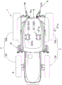
Fig. 1 is a diagram showing a structure and a control block diagram of a tractor.
Fig. 2 is an explanatory diagram for explaining the automatic steering.
Fig. 3 is a diagram showing a state in which the 1 st positioning device and the 2 nd positioning device are mounted in a row in the traveling direction (front-rear direction) on the ceiling of the cab.
Fig. 4A is an explanatory diagram for determining the pitch angle of the tractor (running vehicle).
Fig. 4B is an explanatory diagram for determining the orientation of the tractor (traveling vehicle).
Fig. 4C is an explanatory diagram for determining a roll angle of a tractor (traveling vehicle).
Fig. 5 is a diagram showing a state in which the 1 st positioning device and the 2 nd positioning device are mounted in a row in the width direction (left-right direction) on the ceiling of the cab.
Fig. 6 is an explanatory diagram for explaining the automatic steering.
Fig. 7 is an overall view of the tractor.
Detailed Description
Hereinafter, embodiments of the present invention will be described with reference to the drawings.
The working machine is an agricultural machine such as a tractor, a combine harvester, a rice transplanter, or the like, or a construction machine such as a backhoe, a loader, or the like. The working machine will be described with reference to the tractor 1 as an example.
As shown in fig. 7, the tractor 1 includes a running vehicle (running vehicle body) 3 having a running device 7, a motor 4, and a transmission 5. The running device 7 is a device having front wheels 7F and rear wheels 7R. The front wheel 7F may be a tire type or a track type. The rear wheel 7 may be a tire type or a track type. The motor 4 is a diesel engine, an electric motor, or the like. The transmission 5 can switch the propulsion force of the traveling device 7 by shifting, and can switch the forward and reverse of the traveling device 7. The traveling vehicle 3 is provided with a cab 9, and a driver seat 10 is provided in the cab 9.
Further, a coupling portion 8 formed of a 3-point link mechanism or the like is provided at the rear portion of the traveling vehicle 3. The working device 2 is detachable from the connection portion 8. By coupling the working device 2 to the coupling portion 8, the working device 2 can be towed by the traveling vehicle 3. The working device 2 is a tilling device for tilling, a fertilizer spreading device for spreading fertilizer, a pesticide spreading device for spreading pesticide, a harvesting device for harvesting grass and the like, a spreading device for spreading grass and the like, a grass collecting device for collecting grass and the like, a molding device for molding grass and the like, and the like. Fig. 7 shows an example in which a tilling device is attached as the working device 2.
As shown in fig. 2, the transmission 5 includes a main shaft (propeller shaft) 5a, a main transmission unit 5b, a sub-transmission unit 5c, a shuttle unit 5d, and a PTO power transmission unit 5 e. The propeller shaft 5a is rotatably supported by a case of the transmission 5, and power from a crankshaft of the engine 4 is transmitted to the propeller shaft 5 a. The main transmission unit 5b includes a plurality of gears and a switching mechanism for switching the connection of the gears. The main transmission unit 5b changes the rotation input from the propeller shaft 5a and outputs (shifts) the rotation by appropriately changing the connection (engagement) of the plurality of gears by the conversion mechanism.
The sub-transmission unit 5c includes a plurality of gears and a switching mechanism for changing the connection of the gears, as in the main transmission unit 5 b. The sub-transmission unit 5c changes the rotation input from the main transmission unit 5b and outputs (shifts) the rotation by appropriately changing the connection (meshing) of the plurality of gears by the conversion mechanism.
The shuttle portion 5d includes a shuttle shaft 12 and a forward/reverse switching portion 13. The power output from the sub-transmission portion 5c is transmitted to the shuttle shaft 12 via gears and the like. The front-rear switching unit 13 is configured by, for example, a hydraulic clutch, and switches the rotation direction of the shuttle shaft 12, that is, the forward and reverse of the tractor 1, by turning on and off the hydraulic clutch. The shuttle shaft 12 is connected to a rear wheel differential. The rear wheel differential device rotatably supports a rear axle to which the rear wheel 7R is attached.
The PTO power transmission portion 5e has a PTO propeller shaft 14 and a PTO clutch 15. The PTO propulsion shaft 14 is rotatably supported and can transmit power from the propulsion shaft 5 a. The PTO propeller shaft 14 is connected to the PTO shaft 16 via a gear or the like. The PTO clutch 15 is constituted by, for example, a hydraulic clutch or the like, and switches between a state in which the power of the propeller shaft 5a is transmitted to the PTO propeller shaft 14 and a state in which the power of the propeller shaft 5a is not transmitted to the PTO propeller shaft 14 by turning on and off the hydraulic clutch.
As shown in fig. 2, the tractor 1 includes a steering device 11. The steering device 11 includes a handle (steering wheel) 11a, a steering shaft (rotating shaft) 11b that rotates in accordance with rotation of the handle 11a, and an assist mechanism (power steering mechanism) 11c that assists steering of the handle 11 a. The assist mechanism 11c includes a hydraulic pump 21, a control valve 22 to which hydraulic oil discharged from the hydraulic pump 21 is supplied, and a steering cylinder 23 operated by the control valve 22. The control valve 22 is a solenoid valve that operates based on a control signal. The control valve 22 is, for example, a 3-position switching valve that can be switched by movement of a spool or the like. The control valve 22 can also be switched by steering the steering shaft 11 b. The steering cylinder 23 is connected to an arm (knuckle arm) 24 that changes the orientation of the front wheels 7F.
Therefore, when the driver operates the handle 11a, the switching position and the opening degree of the control valve 22 are switched by the handle 11a, and the steering cylinder 23 is extended and contracted leftward or rightward by the switching position and the opening degree of the control valve 22, whereby the steering direction of the front wheels 7F can be changed. That is, the tractor 1 (the running vehicle body 3) can be manually steered by the steering mechanism 11.
The tractor 1 (the running vehicle body 3) may be automatically steered. As shown in fig. 1, the steering device 11 has an automatic steering mechanism 25. The automatic steering mechanism 25 is a mechanism that performs automatic steering of the running vehicle body 3, and performs automatic steering of the running vehicle body 3 based on the position of the running vehicle body 3 (vehicle body position) and a preset running schedule. The automatic steering mechanism 25 includes a steering motor 26 and a gear mechanism 27. The steering motor 26 is a motor that can control a rotation direction, a rotation speed, a rotation angle, and the like based on the current position. The gear mechanism 27 includes a gear provided on the steering shaft 11b and rotating together with the steering shaft 11b, and a gear provided on the rotating shaft of the steering motor 26 and rotating together with the rotating shaft. When the rotation shaft of the steering motor 26 rotates, the steering shaft 11b automatically rotates (turns) via the gear mechanism 27, and the steering direction of the front wheels 7F can be changed so that the vehicle body position coincides with the planned travel line. The steering mechanism 11 is an example, and is not limited to the above configuration.
As shown in fig. 1 and 3, the tractor 1 includes a plurality of positioning devices 30. The positioning devices 30 are devices that perform positioning based on satellite signals transmitted from positioning satellites. Specifically, the plurality of positioning devices 30 include a 1 st positioning device 31 and a 2 nd positioning device 32. The 1 st Positioning device 31 performs Positioning based on satellite signals of GNSS satellites 101 such as GPS (Global Positioning System). The 2 nd positioning device 32 performs positioning based on the Satellite signals and the like of the Quasi-Zenith satellites (QZSS (Quasi-Zenith Satellite System) satellites) 102 such as みち weaving き.
First, the arrangement of the 1 st positioning device 31 and the 2 nd positioning device 32 will be described.
As shown in fig. 3, the 1 st positioning device 31 and the 2 nd positioning device 32 are respectively provided in the cab 9 of the tractor 1. The 1 st positioning device 31 is disposed at the center in the width direction of the ceiling 9a of the cab 9, and the 2 nd positioning device 32 is also disposed at the center in the width direction of the ceiling 9a of the cab 9. That is, when observing the 1 st positioning device 31 and the 2 nd positioning device 32, the 1 st positioning device 31 and the 2 nd positioning device 32 are arranged at the same position in the width direction of the roof 9a and are arranged in the traveling direction of the traveling vehicle body 3 (the direction orthogonal to the width direction, the front-rear direction).
More specifically, the 1 st positioning device 31 includes a housing 31a that houses electronic/electronic components and the like, and a 1 st antenna 31b that receives satellite signals (1 st satellite signals) of the GNSS satellites 101. Frame 31a is attached to support bracket 40 fixed to ceiling 9a of cab 9 by fastening means 41 such as bolts and nuts. The 1 st antenna 31b receives, as the 1 st satellite signal, the L1 signal (center frequency of 1575.42MHz) and the L2 signal (center frequency of 1227.60MHz) transmitted from the GNSS satellite 101. The L1 signal includes navigation messages, C/A codes, and L1 carriers, and the L2 signal includes at least L2 carriers.
The 2 nd positioning device 32 has a housing 32a for housing electronic/electronic components and the like, and a 2 nd antenna 32 b. The frame 31a is positioned in front of the frame 32a, and is attached to the support bracket 40 to which the frame 31a is attached by a fastener 41. The frame 31a can be detached from the support bracket 40 by loosening the nut screwed with the bolt.
The 2 nd antenna 32b receives at least the L6 signal (center frequency 1278.75MHz) transmitted from the QZSS satellite 102 as the 2 nd satellite signal. The L6 signal contains calibration information (centimeter-level localization enhancement information). The correction information includes satellite clock error information, satellite signal bias error information, satellite orbit error information, convection current circle propagation error information, ionosphere propagation error information, and the like. The 2 nd antenna 32b may receive the L1 signal and the L2 signal transmitted from the QZSS positioning satellite 102 as the 2 nd satellite signal. The 2 nd antenna 32b may receive the 1 st satellite signal (L1 signal and L2 signal) transmitted from the GNSS satellite 101 in addition to the 2 nd satellite signal.
When focusing on the state in which the housing 31a and the housing 32a are attached to the support bracket 40, the 1 st antenna 31b of the 1 st positioning device 31 and the 2 nd antenna 32b of the 2 nd positioning device 32 are aligned at the same position in the width direction of the top portion 9a and at a predetermined distance in the traveling direction. The distance J1 in the traveling direction of the 1 st antenna 31b and the 2 nd antenna 32b is arbitrarily set. In addition, the heights (heights) of the 1 st antenna 31b and the 2 nd antenna 32b with respect to the ground (with respect to the ground) are set to be the same. The top end of the 1 st antenna 31b and the top end of the 2 nd antenna 32b are disposed on the same plane (same horizontal plane) when the tractor 1 is placed horizontally.
Next, the configuration of the 1 st positioning device 31 and the 2 nd positioning device 32 will be described.
The 1 st positioning device 31 includes a housing 31a and a 1 st antenna 31b, as well as a signal processing unit 31c, a 1 st position calculating unit 31d, a 1 st acquiring unit 31e, and a 1 st output unit 31 f. The signal processing unit 31c, the 1 st position calculating unit 31d, the 1 st acquiring unit 31e, and the 1 st output unit 31f are constituted by electronic/electronic components provided in the 1 st positioning device 31, and the like.
The signal processing unit 31c is a part that performs processing of the satellite signal received by the 1 st antenna 31b, and generates observation data by amplifying and demodulating, for example, the L1 signal and the L2 signal received by the 1 st antenna 31 b.
The 1 st position calculator 31d calculates the position (1 st position) based on the observation data (demodulated L1 signal and L2 signal) output from the signal processor 31 c. That is, the 1 st position calculating unit 31d performs the individual positioning based on the observation data (1 st observation data) of the GNSS satellite 101. The 1 st acquisition unit 31e acquires information transmitted from the 2 nd positioning device 32 and outputs the acquired information to the 1 st position calculation unit 31 d. The 1 st output unit 31f outputs the result (the 1 st positioning result) calculated by the 1 st position calculating unit 31d to the 2 nd positioning device 32.
The 2 nd positioning device 32 includes a signal processing unit 32c, a 2 nd position calculating unit 32d, a 2 nd acquiring unit 32e, and a 2 nd output unit 32f in addition to the housing 32a and the 1 st antenna 32 b. The signal processing unit 32c, the 2 nd position calculating unit 32d, the 2 nd acquiring unit 32e, and the 2 nd output unit 32f are constituted by electronic/electronic components and the like provided in the 2 nd positioning device 32.
The signal processing unit 32c is a part that performs processing of the satellite signal received by the 2 nd antenna 32b, and generates observation data by performing amplification and demodulation of the L1 signal, the L2 signal, and the L6 signal received by the 2 nd antenna 32b, for example. The L1 signal and the L2 signal received by the 2 nd antenna 32b may be the 1 st satellite signal of the GNSS satellite 101 or the 2 nd satellite signal of the QZSS positioning satellite 102.
The 2 nd position calculator 32d calculates the position (2 nd position), that is, the three-dimensional coordinates (x2, y2, z2), based on the observation data (demodulated L1 signal, L2 signal, and L6 signal) output from the signal processor 32 c. That is, the 2 nd position calculator 32d precisely measures the position based on the observation data (2 nd observation data) of the QZSS satellite 102. The 2 nd acquisition unit 32e acquires the information transmitted from the 1 st positioning device 31. The 2 nd output unit (correction information output unit) 32f outputs the L6 signal demodulated by the signal processing unit 32c, i.e., the correction information obtained from the L6 signal, to the 1 st positioning device 31.
The 1 st positioning device 31 (the 1 st position calculating unit 31d) can perform positioning alone by using the satellite signals (the L1 signal and the L2 signal) received by the 1 st antenna 31b, but in the present embodiment, positioning can be performed by using the correction information (the correction information output by the correction information output unit 32f) of the satellite signal (the L6 signal) received by the 2 nd antenna 32 b.
When the 1 st acquisition unit 31e acquires the correction information output from the 2 nd output unit (correction information output unit) 32f, the 1 st positioning device 31 obtains the physical position (latitude, longitude, altitude), that is, the three-dimensional coordinates (x1, y1, z1) of the 1 st positioning device 31 using the acquired 1 st observation information (including the satellite clock error information, the satellite signal offset error information, the satellite orbit error information, the orbit propagation error information, and the ionosphere propagation error information) and the L1 signal and the L2 signal (navigation message, C/a code, L1 carrier, and the like) received by the 1 st antenna 31 b. When the position is found using the calibration information, the 1 st output unit 31f outputs the 1 st positioning result including the found position to the 2 nd positioning device 32.
As described above, the 1 st positioning device 31 obtains the position using the calibration information received by the 2 nd positioning device 32 and the L1 signal and the L2 signal received by itself, and thus can calculate the position with high accuracy.
As shown in fig. 1, the 2 nd positioning device 32 includes a state calculation unit 32 g. The state calculating unit 32g is constituted by electronic/electronic components and the like provided in the 2 nd positioning device 32.
The state calculating unit 32g determines any one of the azimuth (azimuth) and the posture of the traveling vehicle body 3 based on the 1 st positioning information obtained by the 1 st positioning device 31 using the L1 signal, the L2 signal, and the L6 signal (correction information) and the 2 nd positioning information obtained by the 2 nd position calculating unit 32d using the L1 signal, the L2 signal, and the L6 signal. For example, the state calculation unit 32g obtains the pitch angle θ 1 as the posture of the traveling vehicle body 3. As shown in fig. 4A, for example, the state calculating unit 32g calculates the pitch angle θ 1 using a three-dimensional base line vector based on the predetermined base line length (distance in the traveling direction) J1 of the 1 st antenna 31b and the 2 nd antenna 32b, the three-dimensional coordinates (x1, y1, z1) calculated by the 1 st position calculating unit 31d, and the three-dimensional coordinates (x2, y2, z2) calculated by the 2 nd position calculating unit 32 d. When the heights (heights) of the 1 st antenna 31b and the 2 nd antenna 32b are different, the state calculation unit 32g obtains the pitch angle θ 1 by removing the height difference between the 1 st antenna 31b and the 2 nd antenna 32 b.
As shown in fig. 4B, the state calculating unit 32g may obtain the azimuth angle θ 2 of the traveling vehicle body 3. For example, the state calculating unit 32g may calculate the azimuth angle θ 2 using a three-dimensional baseline vector obtained from the 1 st positioning information and the 2 nd positioning information. As described above, the state calculation unit 32g can determine the pitch angle θ 1 and the azimuth angle θ 2 of the vehicle body 3.
The state calculating unit 32g may calculate the roll angle θ 3 of the running vehicle body 3. The mounting of the 1 st positioning device 31 and the 2 nd positioning device 32 to the tractor 1 when determining the roll angle θ 3 is different from the above-described embodiment. First, the installation of the 1 st positioning device 31 and the 2 nd positioning device 32 will be described.
As shown in fig. 5, the 1 st positioning device 31 is disposed on one side (left side) in the width direction of the ceiling 9a of the cab 9, and the 2 nd positioning device 32 is disposed on the other side (right side) in the width direction of the ceiling 9a of the cab 9. That is, when observing the 1 st positioning device 31 and the 2 nd positioning device 32, the 1 st positioning device 31 and the 2 nd positioning device 32 are arranged at the same position in the traveling direction of the roof 9a and are arranged side by side in the width direction of the traveling vehicle body 3.
Specifically, when focusing on the state in which the housing 31a and the housing 32a are attached to the support bracket 40, the 1 st antenna 31b of the 1 st positioning device 31 and the 2 nd antenna 32b of the 2 nd positioning device 32 are positioned at the same position in the traveling direction of the top portion 9a and arranged at a predetermined distance in the width direction. The distance J2 in the traveling direction of the 1 st antenna 31b and the 2 nd antenna 32b is set to be several centimeters to several tens of centimeters.
As shown in fig. 4C, for example, the state calculating unit 32g calculates the roll angle θ 3 using a three-dimensional base line vector based on the predetermined base line length (distance in the width direction) J2 of the 1 st antenna 31b and the 2 nd antenna 32b, the three-dimensional coordinates (x1, y1, z1) obtained by the 1 st position calculating unit 31d, and the three-dimensional coordinates (x2, y2, z2) obtained by the 2 nd position calculating unit 32 d.
The pitch angle θ 1, the azimuth angle θ 2, and the roll angle θ 3 may be obtained by arranging the 1 st positioning device 31 at one side or the other side in the width direction, while being arranged at the front or the rear of the 2 nd positioning device 32. In other words, the pitch angle θ 1, the azimuth angle θ 2, and the roll angle θ 3, which are angles in 3 directions, may be obtained by arranging the plurality of 1 st positioning devices 31 in the front-rear direction and the width direction, respectively.
As shown in fig. 1, the 1 st positioning device 31 and the 2 nd positioning device 32 are connected to the control device 50. The control device 50 controls the tractor 1, and controls the work system and the travel system. As control of the work system, the control device 50 raises and lowers the coupling portion 8 in accordance with operation of an operation member provided around the driver's seat 10. Further, as control of the traveling system, the control device 50 controls the change of the rotation speed of the motor and the steering motor 26 of the automatic steering mechanism 25 in accordance with the operation of the accelerator.
Fig. 6 shows a relationship between a position (vehicle body position) Z1 of the tractor 1 during automatic steering and a line to travel Z2. The line to travel Z2 is set in advance by a personal computer or a mobile terminal (smartphone or tablet computer), and is transmitted to the control device 50 or the like by wireless communication, wired communication, or a storage medium. Further, the tractor 1 may be provided with a display device 51 of a touch panel type or the like, and the line to travel Z2 may be input to the display device 51. The line to travel Z2 corresponds to latitude and longitude when set.
In the tractor 1, when the operator performs a predetermined operation to instruct the control device 50 to perform automatic steering, the control device 50 acquires the 2 nd positioning information obtained by the 2 nd positioning device 32, that is, a position included in the 2 nd positioning information as the position (vehicle body position) Z1 of the traveling vehicle body 3. As shown in fig. 6, when the deviation (positional deviation) Δ L1 between the vehicle body position Z1 and the line Z2 is smaller than the threshold value, the control device 50 maintains the rotation angle of the rotation shaft of the steering motor 26. When the positional deviation Δ L1 between the vehicle body position Z1 and the planned travel line Z2 is equal to or greater than the threshold value and the tractor 1 is positioned on the left side with respect to the planned travel line Z2, the control device 50 rotates the rotation shaft of the steering motor 26 so that the steering direction of the tractor 1 is the right direction. When the positional deviation Δ L1 between the vehicle body position Z1 and the planned travel line Z2 is equal to or greater than the threshold value and the tractor 1 is positioned on the right side with respect to the planned travel line Z2, the control device 50 rotates the rotation shaft of the steering motor 26 so that the steering direction of the tractor 1 is the left direction.
In the above-described embodiment, the steering angle of the steering device 11 is changed based on the positional deviation Δ L1 between the vehicle body position Z1 and the planned travel line Z2, but when the orientation (line orientation) F2 of the planned travel line Z2 is different from the orientation (vehicle body orientation) F1 in the traveling direction of the tractor 1, the control device 50 may set the steering angle so that the vehicle body orientation F1 of the tractor 1 coincides with the line orientation F2 of the planned travel line Z2. In this case, the controller 50 obtains an azimuth difference Δ F between the azimuth angle θ 2 (vehicle body azimuth F1) obtained by the state calculating unit 32g and the line azimuth F2, and changes the steering angle of the steering device 11 so that the azimuth difference Δ F becomes zero. The setting of the steering angle in the automatic steering in the above embodiment is an example, and is not limited.
The work machine is provided with: a running vehicle body 3; a 1 st positioning device 31 including a 1 st antenna 31b for receiving a 1 st satellite signal transmitted from the GNSS satellite 101 and a 1 st position calculation unit 31d for performing positioning based on the 1 st satellite signal received by the 1 st antenna 31 b; the 2 nd positioning device 32 includes a 2 nd antenna 32b that receives at least the 2 nd satellite signal transmitted from the QZSS satellite 102, a signal processing unit 32c that generates correction information based on the 2 nd satellite signal received by the 2 nd antenna 32b, a correction information output unit 32f that transmits the correction information to the 1 st positioning device 31, and a 2 nd position calculation unit 32d that performs positioning based on the correction information received by the 2 nd antenna 32b, and the 1 st positioning device 31 and the 2 nd positioning device 32 are provided in the traveling vehicle body 3, and the 1 st position calculation unit 31d performs positioning based on the correction information transmitted from the correction information output unit 32f and the 1 st satellite signal. Thus, the 1 st positioning device 31 that performs positioning based on the 1 st satellite signal of the GNSS satellite 101 can acquire the correction information from the 2 nd positioning device 32 that receives the 2 nd satellite signal transmitted from the QZSS satellite 102, and therefore can perform positioning with high accuracy. For example, the tractor having the 1 st positioning device 31 can be accurately positioned by merely externally attaching the 2 nd positioning device 32 thereto.
The 1 st positioning device 31 transmits the 1 st positioning information obtained by the 1 st positioning device 31 to the 2 nd positioning device 32. Thus, the 2 nd positioning device 32 can acquire the 1 st positioning information obtained by the 1 st positioning device 31, and can thus obtain various states of, for example, a tractor or the like, using the 1 st positioning information.
The 2 nd positioning device 32 includes a state calculation unit 32g that obtains either the azimuth or the attitude of the traveling vehicle body 3 based on the 1 st positioning information and the 2 nd positioning information obtained by the 2 nd positioning device 32. Thus, the attitude of the traveling vehicle body 3 such as the azimuth, roll angle, pitch angle, and the like can be easily obtained by the state calculating unit 32 g.
The 1 st positioning device 31 and the 2 nd positioning device 32 are mounted in a row in the same direction as the traveling direction of the traveling vehicle body 3. This enables, for example, the azimuth and pitch angles in the traveling direction of the traveling vehicle body 3 to be obtained.
The 1 st positioning device 31 and the 2 nd positioning device 32 are mounted in a row in a direction orthogonal to the traveling direction of the traveling vehicle body 3. This enables, for example, the roll angle in the width direction of the traveling vehicle body 3 to be determined.
The working machine includes a support bracket 40 that detachably supports the 2 nd positioning device 32 with respect to the traveling vehicle body 3. This enables the 2 nd positioning device 32 capable of receiving the 2 nd satellite signal transmitted from the QZSS satellite 102 to be attached to and detached from the traveling vehicle body 3 as necessary.
The work machine is provided with: a prime mover 4 provided in the traveling vehicle body 3; a working device 2 attached to a traveling vehicle body 3 and operated by power of a prime mover 4; and a steering device 11 for steering the traveling vehicle body 3. This enables accurate positioning of a tractor or the like that operates the working device 2 by the power of the prime mover 4.
The steering device changes the steering angle of the traveling vehicle body 3 based on any one of the 1 st position and the 2 nd position. This enables steering by the steering device 11 using accurate positioning by the 1 st positioning device 31 and the 2 nd positioning device 32.
The embodiments disclosed herein are to be considered in all respects as illustrative and not restrictive. The scope of the present invention is defined by the claims rather than the description above, and is intended to include all modifications within the meaning and scope equivalent to the claims.
Description of the reference numerals
Tractor 1 (working machine)
2 working device
3-running vehicle body
4 prime mover
11 steering device
31 st position finding device
32 nd 2 nd position finding device
32b 2 nd antenna
32c signal processing unit
32d 2 nd position calculating part
32f correction information output unit
101 GNSS satellite
102 QZSS satellite
Claims (8)
1. A working machine is characterized in that a working machine body,
the work machine includes:
a running vehicle body;
a1 st positioning device comprises: a 1 st antenna for receiving a 1 st satellite signal transmitted from a GNSS satellite; and a 1 st position calculation unit that performs positioning based on the 1 st satellite signal received by the 1 st antenna; and
the 2 nd positioning device includes: a 2 nd antenna for receiving at least a 2 nd satellite signal transmitted from the QZSS satellite; a signal processing unit that generates correction information based on the 2 nd satellite signal received by the 2 nd antenna; a calibration information output unit that transmits the calibration information to the 1 st positioning device; and a 2 nd position calculation unit for performing positioning based on the calibration information received by the 2 nd antenna,
the 1 st positioning device and the 2 nd positioning device are provided in the traveling vehicle body,
the 1 st position calculation unit calculates a position based on the correction information and the 1 st satellite signal transmitted from the correction information output unit.
2. The work machine of claim 1,
the 1 st positioning device transmits the 1 st positioning information obtained by the 1 st positioning device to the 2 nd positioning device.
3. The work machine of claim 2,
the 2 nd positioning device includes a state calculation unit that obtains either one of the direction and the posture of the traveling vehicle body based on the 1 st positioning information and the 2 nd positioning information obtained by the 2 nd positioning device.
4. The work machine according to any one of claims 1 to 3,
the 1 st positioning device and the 2 nd positioning device are mounted in a row in the same direction as the traveling direction of the traveling vehicle body.
5. The work machine according to any one of claims 1 to 4,
the 1 st positioning device and the 2 nd positioning device are mounted in a row in a direction orthogonal to a traveling direction of the traveling vehicle body.
6. The work machine according to any one of claims 1 to 5,
the work implement includes a support bracket that detachably supports the 2 nd positioning device with respect to the traveling vehicle body.
7. The work machine according to any one of claims 1 to 6,
the work machine includes:
a prime mover provided on the traveling vehicle body;
a working device mounted on the traveling vehicle body and operated by power of the prime mover; and
and a steering device for steering the traveling vehicle body.
8. The work machine of claim 7,
the steering device changes a steering angle of the traveling vehicle body based on the positioning.
Applications Claiming Priority (3)
| Application Number | Priority Date | Filing Date | Title |
|---|---|---|---|
| JP2018-133668 | 2018-07-13 | ||
| JP2018133668A JP6987711B2 (en) | 2018-07-13 | 2018-07-13 | Working machine |
| PCT/JP2019/025830 WO2020012987A1 (en) | 2018-07-13 | 2019-06-28 | Working machine |
Publications (1)
| Publication Number | Publication Date |
|---|---|
| CN112166347A true CN112166347A (en) | 2021-01-01 |
Family
ID=69142380
Family Applications (1)
| Application Number | Title | Priority Date | Filing Date |
|---|---|---|---|
| CN201980035588.5A Pending CN112166347A (en) | 2018-07-13 | 2019-06-28 | Working machine |
Country Status (5)
| Country | Link |
|---|---|
| JP (1) | JP6987711B2 (en) |
| KR (1) | KR102370181B1 (en) |
| CN (1) | CN112166347A (en) |
| AU (1) | AU2019302085B2 (en) |
| WO (1) | WO2020012987A1 (en) |
Families Citing this family (7)
| Publication number | Priority date | Publication date | Assignee | Title |
|---|---|---|---|---|
| JP6951494B2 (en) * | 2020-03-26 | 2021-10-20 | 日立建機株式会社 | Work vehicle |
| JP7496732B2 (en) * | 2020-08-06 | 2024-06-07 | 三菱マヒンドラ農機株式会社 | Work vehicles |
| EP4250045B1 (en) | 2020-11-18 | 2025-08-06 | Kubota Corporation | Moving body, data generating unit, and method for generating data |
| EP4250044A4 (en) | 2020-11-18 | 2024-09-04 | Kubota Corporation | MOVING BODY, CONTROL UNIT AND METHOD FOR CONTROLLING THE OPERATION OF A MOVING BODY |
| EP4250046A4 (en) | 2020-11-18 | 2024-07-24 | Kubota Corporation | MOVING BODY, CONTROL UNIT, DATA GENERATION UNIT, METHOD FOR CONTROLLING MOVING BODY MOVEMENT, AND DATA GENERATION METHOD |
| JP7502174B2 (en) | 2020-12-22 | 2024-06-18 | 株式会社クボタ | Agricultural machinery and system and method for controlling an agricultural machinery |
| JP2022172454A (en) * | 2021-05-04 | 2022-11-16 | 国立大学法人岩手大学 | Sowing and harvesting simultaneous work machine |
Citations (6)
| Publication number | Priority date | Publication date | Assignee | Title |
|---|---|---|---|---|
| JP2012233353A (en) * | 2011-05-02 | 2012-11-29 | Komatsu Ltd | Calibration system for hydraulic shovel and calibration method for the hydraulic shovel |
| CN106600962A (en) * | 2016-12-21 | 2017-04-26 | 南京多伦科技股份有限公司 | Vehicle detection apparatus and detection method |
| US20180011202A1 (en) * | 2016-07-06 | 2018-01-11 | Getac Technology Corporation | Method for calculating attitude angle and apparatus therefor |
| CN107589432A (en) * | 2017-10-16 | 2018-01-16 | 驭势科技(北京)有限公司 | Satellite navigation algorithm, navigation system and vehicle based on aerial array |
| US20180106906A1 (en) * | 2016-10-17 | 2018-04-19 | Satellite Positioning Research And Application Center | Positioning processing system, method, computer program, positioning processing device, and user terminal |
| JP2018096799A (en) * | 2016-12-12 | 2018-06-21 | ヤンマー株式会社 | Communication system |
Family Cites Families (8)
| Publication number | Priority date | Publication date | Assignee | Title |
|---|---|---|---|---|
| US8600601B2 (en) * | 2008-12-05 | 2013-12-03 | Leica Geosystems Ag | Positioning system and method |
| JP2015020674A (en) * | 2013-07-22 | 2015-02-02 | 株式会社クボタ | Agricultural work vehicle |
| JP2015112068A (en) * | 2013-12-12 | 2015-06-22 | 株式会社クボタ | Field work machine |
| WO2015198501A1 (en) * | 2014-06-25 | 2015-12-30 | 三菱電機株式会社 | Positioning device, positioning method, and program |
| US9778368B2 (en) * | 2014-09-07 | 2017-10-03 | Trimble Inc. | Satellite navigation using side by side antennas |
| JP6422912B2 (en) | 2016-04-06 | 2018-11-14 | 株式会社クボタ | POSITIONING DETECTION DEVICE AND WORKING MACHINE HAVING POSITIONING DETECTION DEVICE |
| JP6688545B2 (en) * | 2016-11-10 | 2020-04-28 | ヤンマー株式会社 | Combine |
| JP6733619B2 (en) * | 2017-07-07 | 2020-08-05 | 株式会社デンソー | Positioning device |
-
2018
- 2018-07-13 JP JP2018133668A patent/JP6987711B2/en active Active
-
2019
- 2019-06-28 WO PCT/JP2019/025830 patent/WO2020012987A1/en not_active Ceased
- 2019-06-28 KR KR1020207030775A patent/KR102370181B1/en active Active
- 2019-06-28 CN CN201980035588.5A patent/CN112166347A/en active Pending
- 2019-06-28 AU AU2019302085A patent/AU2019302085B2/en active Active
Patent Citations (6)
| Publication number | Priority date | Publication date | Assignee | Title |
|---|---|---|---|---|
| JP2012233353A (en) * | 2011-05-02 | 2012-11-29 | Komatsu Ltd | Calibration system for hydraulic shovel and calibration method for the hydraulic shovel |
| US20180011202A1 (en) * | 2016-07-06 | 2018-01-11 | Getac Technology Corporation | Method for calculating attitude angle and apparatus therefor |
| US20180106906A1 (en) * | 2016-10-17 | 2018-04-19 | Satellite Positioning Research And Application Center | Positioning processing system, method, computer program, positioning processing device, and user terminal |
| JP2018096799A (en) * | 2016-12-12 | 2018-06-21 | ヤンマー株式会社 | Communication system |
| CN106600962A (en) * | 2016-12-21 | 2017-04-26 | 南京多伦科技股份有限公司 | Vehicle detection apparatus and detection method |
| CN107589432A (en) * | 2017-10-16 | 2018-01-16 | 驭势科技(北京)有限公司 | Satellite navigation algorithm, navigation system and vehicle based on aerial array |
Also Published As
| Publication number | Publication date |
|---|---|
| AU2019302085B2 (en) | 2022-06-30 |
| JP2020012680A (en) | 2020-01-23 |
| KR20200135509A (en) | 2020-12-02 |
| AU2019302085A1 (en) | 2020-12-17 |
| WO2020012987A1 (en) | 2020-01-16 |
| JP6987711B2 (en) | 2022-01-05 |
| KR102370181B1 (en) | 2022-03-04 |
Similar Documents
| Publication | Publication Date | Title |
|---|---|---|
| CN112166347A (en) | Working machine | |
| JP6422912B2 (en) | POSITIONING DETECTION DEVICE AND WORKING MACHINE HAVING POSITIONING DETECTION DEVICE | |
| JP7524410B2 (en) | Work vehicles | |
| JP7787771B2 (en) | Autonomous Driving System | |
| CN112312760B (en) | Work vehicle | |
| JP7233916B2 (en) | WORK VEHICLE CONTROL DEVICE, WORK VEHICLE, AND WORK VEHICLE CONTROL METHOD | |
| JP6879896B2 (en) | Satellite positioning system for work platforms | |
| KR20220002656A (en) | work vehicle | |
| JP2022164924A (en) | work vehicle | |
| CN113924239B (en) | Work vehicles | |
| JP7106419B2 (en) | work vehicle | |
| JP7161364B2 (en) | work vehicle | |
| US11543246B1 (en) | Rear axle center locating | |
| JP7062542B2 (en) | Working machine positioning system and working machine positioning method | |
| JP2020000020A (en) | Work vehicle | |
| JP7179565B2 (en) | work vehicle | |
| JP6995711B2 (en) | Working machine positioning system | |
| JP7125206B2 (en) | work vehicle | |
| JP6938444B2 (en) | Work machine | |
| JP2020012679A (en) | Satellite signal receiver and positioning device including satellite signal receiver | |
| EP4409232A1 (en) | Rear axle center locating | |
| JP2025147386A (en) | Work vehicle control method, work vehicle control program, work vehicle control system, and work system | |
| JP2020178628A (en) | Autonomous travel work vehicle of field |
Legal Events
| Date | Code | Title | Description |
|---|---|---|---|
| PB01 | Publication | ||
| PB01 | Publication | ||
| SE01 | Entry into force of request for substantive examination | ||
| SE01 | Entry into force of request for substantive examination | ||
| RJ01 | Rejection of invention patent application after publication | ||
| RJ01 | Rejection of invention patent application after publication |
Application publication date: 20210101 |