CN112144234A - Drum washing machine - Google Patents
Drum washing machine Download PDFInfo
- Publication number
- CN112144234A CN112144234A CN201910498346.1A CN201910498346A CN112144234A CN 112144234 A CN112144234 A CN 112144234A CN 201910498346 A CN201910498346 A CN 201910498346A CN 112144234 A CN112144234 A CN 112144234A
- Authority
- CN
- China
- Prior art keywords
- cylinder
- sliding
- inner cylinder
- motor
- rod
- Prior art date
- Legal status (The legal status is an assumption and is not a legal conclusion. Google has not performed a legal analysis and makes no representation as to the accuracy of the status listed.)
- Withdrawn
Links
- 238000005406 washing Methods 0.000 title claims abstract description 48
- 230000033001 locomotion Effects 0.000 claims abstract description 31
- 230000009471 action Effects 0.000 claims abstract description 20
- 230000005540 biological transmission Effects 0.000 claims abstract description 15
- 241000894006 Bacteria Species 0.000 claims abstract description 5
- 230000007246 mechanism Effects 0.000 claims description 14
- 238000013016 damping Methods 0.000 claims description 4
- 230000007306 turnover Effects 0.000 claims description 4
- 230000001095 motoneuron effect Effects 0.000 claims description 2
- 238000004140 cleaning Methods 0.000 description 8
- 238000010586 diagram Methods 0.000 description 3
- 239000012459 cleaning agent Substances 0.000 description 2
- 230000000694 effects Effects 0.000 description 2
- 230000004048 modification Effects 0.000 description 2
- 238000012986 modification Methods 0.000 description 2
- 230000009286 beneficial effect Effects 0.000 description 1
- 230000007547 defect Effects 0.000 description 1
- 230000036541 health Effects 0.000 description 1
- 238000000034 method Methods 0.000 description 1
Images


Classifications
-
- D—TEXTILES; PAPER
- D06—TREATMENT OF TEXTILES OR THE LIKE; LAUNDERING; FLEXIBLE MATERIALS NOT OTHERWISE PROVIDED FOR
- D06F—LAUNDERING, DRYING, IRONING, PRESSING OR FOLDING TEXTILE ARTICLES
- D06F37/00—Details specific to washing machines covered by groups D06F21/00 - D06F25/00
- D06F37/30—Driving arrangements
-
- D—TEXTILES; PAPER
- D06—TREATMENT OF TEXTILES OR THE LIKE; LAUNDERING; FLEXIBLE MATERIALS NOT OTHERWISE PROVIDED FOR
- D06F—LAUNDERING, DRYING, IRONING, PRESSING OR FOLDING TEXTILE ARTICLES
- D06F37/00—Details specific to washing machines covered by groups D06F21/00 - D06F25/00
-
- D—TEXTILES; PAPER
- D06—TREATMENT OF TEXTILES OR THE LIKE; LAUNDERING; FLEXIBLE MATERIALS NOT OTHERWISE PROVIDED FOR
- D06F—LAUNDERING, DRYING, IRONING, PRESSING OR FOLDING TEXTILE ARTICLES
- D06F37/00—Details specific to washing machines covered by groups D06F21/00 - D06F25/00
- D06F37/42—Safety arrangements, e.g. for stopping rotation of the receptacle upon opening of the casing door
Landscapes
- Engineering & Computer Science (AREA)
- Textile Engineering (AREA)
- Transmission Devices (AREA)
Abstract
The invention relates to a drum washing machine, which comprises a washing machine shell, wherein an outer barrel (2) is arranged in the washing machine shell, an inner barrel (1) for washing clothes is arranged in the outer barrel (2), the inner barrel (1) rotates to wash clothes under the action of an inner barrel driving motor (4), the inner barrel (1) can enter and exit the outer barrel (2) in a linear motion mode and enables a space between the outer wall of the inner barrel (1) and the inner wall of the outer barrel (2) to be exposed so as to conveniently remove dirt and harmful bacteria, a motor driving part (13) of the inner barrel driving motor (4) is fixed at the bottom of the inner barrel (1), and the inner barrel driving motor (4) is arranged at the bottom of the outer barrel; when the motor transmission piece (13) is positioned in a motor shaft hole (41) of the inner cylinder driving motor (4), the inner cylinder (1) can rotate to wash clothes; when the motor transmission piece (13) leaves the motor shaft hole (41) of the inner cylinder driving motor (4), the inner cylinder (1) can be separated from the outer cylinder (2).
Description
Technical Field
The invention relates to a drum washing machine, in particular to a drum washing machine for household use.
Background
After the washing machine is used for a period of time, the appearance looks bright as new, but dirt and filth are hidden in the space between the outer wall of the inner barrel and the inner wall of the outer barrel, the dirt contains harmful bacteria, and if the dirt is not removed in time, the damage to the health of people can be caused.
The prior art mainly comprises the following modes and the following defects for removing dirt between an inner barrel and an outer barrel:
(1) the inner barrel is taken out to be cleaned in the existing physical disassembly mode, so that dirt can be completely and thoroughly removed, but common consumers cannot disassemble or disassemble easily, and the cleaning machine cannot be widely popularized.
(2) In the prior art, the dirt can be cleaned by using a cleaning agent, but the cleaning effect of the cleaning agent is poor in practice, and the cleaning effect cannot be checked by naked eyes or equipment after the cleaning.
(3) The Chinese patent application: a washing machine convenient for cleaning, application No.: 2019101348908, which discloses that the inner barrel can move relative to the outer barrel, but generally requires a person to manually pull out or push in the inner barrel, and cannot automatically extend or retract the inner barrel by control commands.
(4) The Chinese patent application: a washing machine convenient for cleaning, application No.: 2019101348908, which discloses that the inner barrel can move relative to the outer barrel, the locking mechanism between the inner and outer barrels is overly complex and takes up too much space.
(5) The Chinese patent application: a washing machine convenient for cleaning, application No.: 2019101348908, the patent discloses that the inner cylinder can move relative to the outer cylinder, but the stability and smoothness of the two running by the guiding mode of the matching of the sliding piece and the sliding rail need to be improved.
(6) When the inner drum of the washing machine is pulled out of the outer drum, the inner drum and the outer drum need to be freely separated, but when the inner drum returns to the outer drum after washing, the locking relation between the inner drum and the outer drum needs to be ensured, otherwise, when the inner drum rotates at high speed, the inner drum can be displaced relative to the outer drum, and the safe use of the washing machine is influenced.
Disclosure of Invention
The invention designs a drum washing machine, which solves the technical problem that when an inner drum of the washing machine is pulled out from an outer drum, the inner drum and the outer drum need to be freely separated, but when the inner drum returns to the outer drum after washing, the locking relation between the inner drum and the outer drum needs to be ensured, otherwise, when the inner drum rotates at high speed, the inner drum can be displaced relative to the outer drum and the safe use of the washing machine is influenced.
In order to solve the technical problems, the invention adopts the following scheme:
a drum washing machine comprises a washing machine shell, wherein an outer drum (2) is arranged in the washing machine shell, an inner drum (1) for washing clothes is arranged in the outer drum (2), the inner drum (1) rotates to wash clothes under the action of an inner drum driving motor (4), the inner drum (1) can enter and exit the outer drum (2) in a linear motion mode and enables a space between the outer wall of the inner drum (1) and the inner wall of the outer drum (2) to be exposed so as to conveniently remove dirt and harmful bacteria, a motor transmission piece (13) of the inner drum driving motor (4) is fixed at the bottom of the inner drum (1), and the inner drum driving motor (4) is arranged at the bottom of the outer drum (2); when the motor transmission piece (13) is positioned in a motor shaft hole (41) of the inner cylinder driving motor (4), the inner cylinder (1) can rotate to wash clothes; when the motor transmission part (13) leaves the motor shaft hole (41) of the inner cylinder driving motor (4), the inner cylinder (1) can be separated from the outer cylinder (2).
Further, a locking and unlocking mechanism is arranged between the inner barrel (1) and the outer barrel (2) to ensure that the inner barrel (1) is separated from or connected with the outer barrel (2).
Further, locking and unlocking mechanism includes first electro-magnet (61) and bearing (62), first electro-magnet (61) is installed the bottom of urceolus (2), bearing (62) include fixed part and movable part, the movable part can for the fixed part rotates, the movable part pass through connecting portion (14) with inner tube (1) is connected, the fixed part can by first electro-magnet (61) adsorbs the messenger motor drive spare (13) keep being located in motor shaft hole (41) of inner tube driving motor (4).
Further, the locking and unlocking mechanism comprises a second magnet (63) and a third magnet (64), the second magnet (63) is installed at the edge of the opening of the inner barrel (1), the third magnet (64) is installed on the barrel cover, and the contact surface between the second magnet (63) and the third magnet (64) is ensured to be in the same polarity repulsion, so that the motor transmission piece (13) is located in the motor shaft hole (41) of the inner barrel driving motor (4), and the barrel cover and the panel (3) can be locked.
Further, the barrel cover comprises an inner barrel cover (11) and an outer barrel cover (12), the inner barrel cover (11) is used for closing or opening the opening of the inner barrel (1), and the outer barrel cover (12) is used for closing or opening the annular opening between the inner barrel (1) and the outer barrel (2).
Further, a damping device (5) is arranged between the outer cylinder (1) and the washing machine shell.
Further, the inner cylinder (1) can pass in and out the outer cylinder (2) in a linear motion mode under the action of a linear moving structure, the linear moving structure comprises sliding parts and sliding rails, the inner cylinder (1) is directly or indirectly connected with one or more sliding parts, one or more sliding rails are correspondingly arranged on the outer wall or the inner wall of the outer cylinder (2) in the axial direction, and the sliding parts can slide in the sliding rails to enable the inner cylinder (1) to freely pass in and out the outer cylinder (2).
Further, the inner cylinder (1) can pass in and out the outer cylinder (2) in a linear motion mode under the action of a linear moving structure, the linear moving structure comprises a sliding part and sliding rails, the inner cylinder (1) is directly or indirectly connected with one or more sliding rails, one or more sliding parts are correspondingly arranged on the outer wall or the inner wall of the outer cylinder (2) in the axial direction, and the sliding part can realize that the inner cylinder (1) freely passes in and out the outer cylinder (2) through sliding in the sliding rails.
Further, the inner cylinder (1) can move in and out of the outer cylinder (2) in a linear motion mode under the action of a linear moving structure, and the linear moving structure comprises a sliding part and a guide rod; the sliding piece is connected with the inner cylinder (1), the guide rod is arranged on the outer side or the inner side of the outer cylinder (2) and along the axial direction of the outer cylinder (2), the guide rod penetrates through the through hole on the sliding piece so that the sliding piece can freely move along the axial direction of the guide rod, and the moving sliding piece drives the inner cylinder (1) to freely move in and out of the outer cylinder (2);
further, the inner cylinder (1) can move in and out of the outer cylinder (2) in a linear motion mode under the action of a linear moving structure, the linear moving structure comprises a sliding part, a guide rod and a push rod, the sliding part is directly or indirectly connected with the inner cylinder through the push rod, the guide rod is arranged on the outer side or the inner side of the outer cylinder and along the axial direction of the outer cylinder (2), the guide rod penetrates through a through hole in the sliding part to enable the sliding part to move freely along the axial direction of the guide rod, and the push rod is pushed and pulled to enable the sliding part to drive the inner cylinder (1) to move in and out of the outer cylinder (2) freely.
Further, the inner cylinder (1) can move in and out of the outer cylinder (2) in a linear motion mode under the action of a linear moving structure, and the linear moving structure comprises a sliding rod and a guide block; the sliding rod is connected with the inner cylinder (1), is located on the outer side or the inner side of the outer cylinder (2) and is axially arranged along the outer cylinder (2), a guide hole is formed in the guide block, the sliding rod penetrates through the guide hole and can axially move back and forth relative to the guide hole, and the moving sliding rod drives the inner cylinder (1) to freely enter and exit the outer cylinder (2).
Further, the inner cylinder (1) can move in and out of the outer cylinder (2) in a linear motion manner under the action of an automatic linear moving structure; the automatic linear moving structure comprises a sliding part, a guide rod and an inner cylinder telescopic driving device; the power device of the inner cylinder telescopic driving device is an air cylinder or a hydraulic cylinder, the sliding part is connected with the inner cylinder (1), the inner cylinder telescopic driving device directly acts on the sliding part to enable the sliding part to axially move along the guide rod, and the moving sliding part drives the inner cylinder (1) to freely enter and exit the outer cylinder (2).
Further, the inner cylinder (1) can move in and out of the outer cylinder (2) in a linear motion manner under the action of an automatic linear moving structure; the automatic linear moving structure comprises a sliding part, a guide rod, a push rod and an inner cylinder telescopic driving device; the power device of the inner cylinder telescopic driving device is an air cylinder or a hydraulic cylinder, the sliding part is directly or indirectly connected with the inner cylinder (1) through the push rod, the inner cylinder telescopic driving device directly pushes and pulls the push rod to enable the push rod to move axially along the push rod, and the moving push rod drives the inner cylinder (1) to freely enter and exit the outer cylinder (2).
Further, the inner cylinder (1) can move in and out of the outer cylinder (2) in a linear motion manner under the action of an automatic linear moving structure; the automatic linear moving structure comprises a sliding rod, a guide block and an inner cylinder telescopic driving device; the power device of the inner cylinder telescopic driving device is an air cylinder or a hydraulic cylinder, one end of a sliding rod is connected with the inner cylinder (1), the other end of the sliding rod is connected with the inner cylinder telescopic driving device, the sliding rod is located on the outer side or the inner side of the outer cylinder (2) and is arranged along the axial direction of the outer cylinder (2), a guide hole is formed in a guide block, the sliding rod penetrates through the guide hole and can move back and forth relative to the axial direction of the guide hole under the action of the inner cylinder telescopic driving device, and the moving sliding rod drives the inner cylinder (1) to freely pass in and out the outer cylinder (2).
Further, the inner cylinder (1) can move in and out of the outer cylinder (2) in a linear motion manner under the action of an automatic linear moving structure; the automatic linear moving structure comprises a push rod, a motor, a gear and a rack, the motor acts on the gear to rotate, the rack is connected with one end of the push rod, the other end of the push rod is directly or indirectly connected with the inner cylinder, the motor acts on the gear to rotate positively and negatively, the push rod is connected with the inner cylinder, when the gear rotates positively and negatively, the rack is pushed and pulled to do linear motion, the push rod is made to move linearly, and the moving push rod drives the inner cylinder to freely enter and exit the outer cylinder;
further, the inner cylinder (1) can move in and out of the outer cylinder (2) in a linear motion manner under the action of an automatic linear moving structure; the linear motion structure includes slider, motor, at least sprocket and chain, the motor effect the sprocket rotates and makes the chain round trip movement between two sprockets, the one end and the inner tube (1) of slider are connected, the other end of slider pass through the connecting piece with linear motion's part is connected to the chain, and when sprocket drive chain, linear motion's chain drives slider also is linear motion, removes the slider drives the business turn over of inner tube (1) freedom urceolus (2).
Further, the inner cylinder (1) can move in and out of the outer cylinder (2) in a linear motion manner under the action of an automatic linear moving structure; the automatic linear moving structure comprises a motor, a screw rod and a sliding piece; the sliding part is connected with the inner barrel (1) and is provided with a threaded hole, the screw rod penetrates through the threaded hole of the sliding part (4) and is connected with the sliding part through threads, and the screw rod can only rotate but cannot move; when the motor enables the screw to rotate, the sliding piece moves back and forth along the axial direction of the screw, and finally the inner cylinder (1) is driven to freely enter and exit the outer cylinder (2).
Further, the inner cylinder (1) can move in and out of the outer cylinder (2) in a linear motion manner under the action of an automatic linear moving structure; the automatic linear moving structure comprises a motor, a screw rod and a fixed block; the motor with the one end of screw rod is connected, inner tube (1) with the other end of screw rod is connected through the bearing, the bearing is ensured that the screw rod can rotate and can drive inner tube (1) removes, fixed block fixed connection be in on urceolus (2) inner wall or the outer wall to be equipped with the screw hole, the screw hole with the screw rod cooperates, when the motor makes the screw rod rotatory, the motor with the screw rod can for screw hole axial round trip movement, the screw rod of removal drives the business turn over of inner tube (1) freedom urceolus (2).
Further, the safety door is locked with the inner barrel (1), the inner barrel cover, the outer barrel (2) and the outer barrel cover or the panel through a locking mechanism.
Compared with the prior drum washing machine, the drum washing machine has the following beneficial effects:
(1) a locking and unlocking mechanism is arranged between the inner cylinder and the outer cylinder to ensure that the inner cylinder and the outer cylinder are separated or connected.
(2) The inner cylinder can automatically enter and exit the outer cylinder through the inner cylinder telescopic driving device, manual push-pull is not needed, and the use and cleaning are convenient.
Drawings
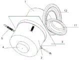
FIG. 1: the invention discloses an appearance schematic diagram of a roller washing machine;
FIG. 2: the invention discloses a structural schematic diagram of a drum washing machine embodiment;
FIG. 3: the invention discloses a structural schematic diagram of a drum washing machine.
Description of reference numerals:
1, an inner cylinder; 11-inner cylinder cover; 12-outer cylinder cover; 13-motor drive member; 14-a connecting portion; 2, an outer cylinder; 3-a panel; 4, a motor; 41-motor shaft hole; 5, a damping device; 61 — a first electromagnet; 62-a bearing; 63-a second magnet; 64-third magnet.
Detailed Description
The invention is further illustrated below with reference to fig. 1 to 3:
as shown in fig. 1, a drum washing machine comprises a washing machine shell, an outer drum 2 is arranged in the washing machine shell, an inner drum 1 for washing clothes is arranged in the outer drum 2, the inner drum 1 rotates to wash clothes under the action of an inner drum driving motor 4, the inner drum 1 can enter and exit the outer drum 2 in a linear motion mode and enables a space between the outer wall of the inner drum 1 and the inner wall of the outer drum 2 to be exposed so as to conveniently remove dirt and harmful bacteria, a motor driving part 13 of the inner drum driving motor 4 is fixed at the bottom of the inner drum 1, and the inner drum driving motor 4 is arranged at the bottom of the outer; when the motor transmission piece 13 is positioned in the motor shaft hole 41 of the inner cylinder driving motor 4, the inner cylinder 1 can rotate to wash clothes; when the motor transmission member 13 leaves the motor shaft hole 41 of the inner cylinder driving motor 4, the inner cylinder 1 can be separated from the outer cylinder 2.
The barrel cover comprises an inner barrel cover 11 and an outer barrel cover 12, the inner barrel cover 11 is used for closing or opening an opening of the inner barrel 1, and the outer barrel cover 12 is used for closing or opening an annular opening between the inner barrel 1 and the outer barrel 2.
A damping device 5 is arranged between the outer cylinder 1 and the shell of the washing machine.
The first embodiment is as follows:
as shown in fig. 2, a locking and unlocking mechanism is arranged between the inner cylinder 1 and the outer cylinder 2 to ensure that the inner cylinder 1 is separated from or connected with the outer cylinder 2. The locking and unlocking mechanism comprises a second magnet 63 and a third magnet 64, the second magnet 63 is arranged at the edge of the opening of the inner cylinder 1, the third magnet 64 is arranged on the barrel cover, the contact surface between the second magnet 63 and the third magnet 64 is in the same polarity repulsion, the motor transmission piece 13 is ensured to be positioned in the motor shaft hole 41 of the inner cylinder driving motor 4, and the barrel cover and the panel 3 can be locked.
When the third magnet 64 on the barrel cover contacts with the second magnet 63 on the inner barrel 1, the third magnet 64 always moves towards the bottom direction of the outer barrel 2 by acting on the second magnet 63 due to the same magnetic poles repulsion, and the barrel cover can be locked with the panel 3, so that the third magnet 64 and the second magnet 63 are always ensured to be same magnetic poles repulsion.
Example two:
as shown in fig. 3, a locking and unlocking mechanism is arranged between the inner cylinder 1 and the outer cylinder 2 to ensure that the inner cylinder 1 is separated from or connected with the outer cylinder 2. The locking and unlocking mechanism comprises a first electromagnet 61 and a bearing 62, the first electromagnet 61 is installed at the bottom of the outer barrel 2, the bearing 62 comprises a fixed part and a movable part, the movable part can rotate relative to the fixed part, the movable part is connected with the inner barrel 1 through the connecting part 14, and the fixed part can be adsorbed by the first electromagnet 61 to enable the motor driving part 13 to be kept in the motor shaft hole 41 of the inner barrel driving motor 4.
When the motor actuator 13 is held in the motor shaft hole 41 of the inner cylinder drive motor 4, the first electromagnet 61 is activated, and the first electromagnet 61 connects the outer cylinder 2 with the fixed portion (bearing outer race) of the bearing 62, but the movable portion (bearing inner race) of the bearing 62 is not affected thereby. When the inner cylinder driving motor 4 operates, the motor transmission member 13 rotates and drives the inner cylinder 1 to rotate, but is connected to the bearing fixing portion by the first electromagnet 61 so as to ensure that the motor transmission member 13 remains in the motor shaft hole 41 of the inner cylinder driving motor 4. When the first electromagnet 1 is turned off, the bearing is no longer subjected to the magnetic force in the axial direction, and the inner cylinder 1 can be separated from the outer cylinder 2.
The invention is described above with reference to the accompanying drawings, it is obvious that the implementation of the invention is not limited in the above manner, and it is within the scope of the invention to adopt various modifications of the inventive method concept and solution, or to apply the inventive concept and solution directly to other applications without modification.
Claims (9)
1. A drum washing machine comprises a washing machine shell, an outer drum (2) is arranged in the washing machine shell, an inner drum (1) for washing clothes is arranged in the outer drum (2), the inner drum (1) rotates to wash clothes under the action of an inner drum driving motor (4), the inner drum (1) can enter and exit the outer drum (2) in a linear motion mode and enables a space between the outer wall of the inner drum (1) and the inner wall of the outer drum (2) to be exposed, so that dirt and harmful bacteria can be conveniently removed, and the drum washing machine is characterized in that:
a motor transmission part (13) of the inner cylinder driving motor (4) is fixed at the bottom of the inner cylinder (1), and the inner cylinder driving motor (4) is arranged at the bottom of the outer cylinder (2);
when the motor transmission piece (13) is positioned in a motor shaft hole (41) of the inner cylinder driving motor (4), the inner cylinder (1) can rotate to wash clothes; when the motor transmission part (13) leaves the motor shaft hole (41) of the inner cylinder driving motor (4), the inner cylinder (1) can be separated from the outer cylinder (2).
2. A drum washing machine according to claim 1, characterized in that: a locking and unlocking mechanism is arranged between the inner barrel (1) and the outer barrel (2) to ensure that the inner barrel (1) and the outer barrel (2) are separated or connected.
3. A drum washing machine according to claim 2, characterized in that: locking release mechanism includes first electro-magnet (61) and bearing (62), first electro-magnet (61) is installed the bottom of urceolus (2), bearing (62) include fixed part and movable part, the movable part can for the fixed part rotates, the movable part pass through connecting portion (14) with inner tube (1) is connected, the fixed part can by first electro-magnet (61) adsorb the messenger motor drive spare (13) keep being located in motor shaft hole (41) of inner tube driving motor (4).
4. A drum washing machine according to claim 2, characterized in that: the locking and unlocking mechanism comprises a second magnet (63) and a third magnet (64), the second magnet (63) is installed at the edge of the opening of the inner barrel (1), the third magnet (64) is installed on the barrel cover, and the contact surface between the second magnet (63) and the third magnet (64) is ensured that the motor transmission piece (13) is located in the motor shaft hole (41) of the inner barrel driving motor (4) through like-pole repulsion, and the barrel cover and the panel (3) can be locked.
5. A drum washing machine according to claim 4, characterized in that: the barrel cover comprises an inner barrel cover (11) and an outer barrel cover (12), the inner barrel cover (11) is used for closing or opening the opening of the inner barrel (1), and the outer barrel cover (12) is used for closing or opening the opening between the inner barrel (1) and the outer barrel (2).
6. A drum washing machine according to any one of claims 1-5, characterized in that: and a damping device (5) is arranged between the outer cylinder (1) and the shell of the washing machine.
7. A drum washing machine according to any one of claims 1-6, characterized in that: the inner cylinder (1) can move in and out of the outer cylinder (2) in a linear motion mode under the action of a linear moving structure, the linear moving structure comprises sliding parts and sliding rails, the inner cylinder (1) is directly or indirectly connected with one or more sliding parts, one or more sliding rails are correspondingly arranged on the outer wall or inner wall of the outer cylinder (2) in the axial direction, and the sliding parts can realize that the inner cylinder (1) freely moves in and out of the outer cylinder (2) through sliding in the sliding rails;
or,
the linear moving structure comprises sliding parts and sliding rails, one or more sliding rails are directly or indirectly connected with the inner cylinder (1), one or more sliding parts are correspondingly arranged on the outer wall or the inner wall of the outer cylinder (2) in the axial direction, and the sliding parts can realize that the inner cylinder (1) freely enters and exits the outer cylinder (2) through sliding in the sliding rails;
or,
the linear moving structure comprises a sliding piece and a guide rod; the sliding piece is connected with the inner cylinder (1), the guide rod is arranged on the outer side or the inner side of the outer cylinder (2) and along the axial direction of the outer cylinder (2), the guide rod penetrates through the through hole on the sliding piece so that the sliding piece can freely move along the axial direction of the guide rod, and the moving sliding piece drives the inner cylinder (1) to freely move in and out of the outer cylinder (2);
or,
the linear moving structure comprises a sliding part, a guide rod and a push rod, the sliding part is directly or indirectly connected with the inner cylinder through the push rod, the guide rod is arranged on the outer side or the inner side of the outer cylinder and along the axial direction of the outer cylinder (2), the guide rod penetrates through a through hole in the sliding part to enable the sliding part to freely move along the axial direction of the guide rod, and the push rod is pushed and pulled to enable the sliding part to drive the inner cylinder (1) to freely move in and out of the outer cylinder (2);
or,
the linear moving structure comprises a sliding rod and a guide block; the sliding rod is connected with the inner cylinder (1), is located on the outer side or the inner side of the outer cylinder (2) and is axially arranged along the outer cylinder (2), a guide hole is formed in the guide block, the sliding rod penetrates through the guide hole and can axially move back and forth relative to the guide hole, and the moving sliding rod drives the inner cylinder (1) to freely enter and exit the outer cylinder (2).
8. A drum washing machine according to any one of claims 1-6, characterized in that: the inner cylinder (1) can move in and out of the outer cylinder (2) in a linear motion manner under the action of an automatic linear moving structure;
the automatic linear moving structure comprises a sliding part, a guide rod and an inner cylinder telescopic driving device; the power device of the inner cylinder telescopic driving device is an air cylinder or a hydraulic cylinder, the sliding part is connected with the inner cylinder (1), the inner cylinder telescopic driving device directly acts on the sliding part to enable the sliding part to axially move along the guide rod, and the moving sliding part drives the inner cylinder (1) to freely enter and exit the outer cylinder (2);
or the automatic linear moving structure comprises a sliding part, a guide rod, a push rod and an inner cylinder telescopic driving device; the power device of the inner cylinder telescopic driving device is an air cylinder or a hydraulic cylinder, the sliding part is directly or indirectly connected with the inner cylinder (1) through the push rod, the inner cylinder telescopic driving device directly pushes and pulls the push rod to enable the push rod to move axially along the push rod, and the moving push rod drives the inner cylinder (1) to freely enter and exit the outer cylinder (2);
or the automatic linear moving structure comprises a sliding rod, a guide block and an inner cylinder telescopic driving device; the power device of the inner cylinder telescopic driving device is an air cylinder or a hydraulic cylinder, one end of a sliding rod is connected with the inner cylinder (1), the other end of the sliding rod is connected with the inner cylinder telescopic driving device, the sliding rod is positioned on the outer side or the inner side of the outer cylinder (2) and is axially arranged along the outer cylinder (2), a guide hole is formed in a guide block, the sliding rod penetrates through the guide hole and can axially move back and forth relative to the guide hole under the action of the inner cylinder telescopic driving device, and the moving sliding rod drives the inner cylinder (1) to freely enter and exit the outer cylinder (2);
or the automatic linear moving structure comprises a push rod, a motor, a gear and a rack, the motor acts on the gear to rotate, the rack is connected with one end of the push rod, the other end of the push rod is directly or indirectly connected with the inner cylinder, the motor acts on the gear to rotate positively and negatively, the push rod is connected with the inner cylinder, when the gear rotates positively and negatively, the rack is pushed and pulled to move linearly, the push rod is enabled to move linearly, and the moving push rod drives the inner cylinder to freely enter and exit the outer cylinder;
or, the rectilinear movement structure includes slider, motor, at least sprocket and chain, the motor effect the sprocket rotates and makes the chain round trip movement between two sprockets, the one end and the inner tube (1) of slider are connected, the other end of slider pass through the connecting piece with the part that the chain was rectilinear motion is connected, and when sprocket drive chain, the chain that is rectilinear motion drives slider also is rectilinear movement, removes the slider drives the business turn over that inner tube (1) is free urceolus (2)
Or, the automatic linear moving structure comprises a motor, a screw rod and a sliding part; the sliding part is connected with the inner barrel (1) and is provided with a threaded hole, the screw rod penetrates through the threaded hole of the sliding part (4) and is connected with the sliding part through threads, and the screw rod can only rotate but cannot move; when the motor rotates the screw rod, the sliding part moves back and forth along the axial direction of the screw rod and finally drives the inner cylinder (1) to freely enter and exit the outer cylinder (2);
or the automatic linear moving structure comprises a motor, a screw rod and a fixed block; the motor with the one end of screw rod is connected, inner tube (1) with the other end of screw rod is connected through the bearing, the bearing is ensured that the screw rod can rotate and can drive inner tube (1) removes, fixed block fixed connection be in on urceolus (2) inner wall or the outer wall to be equipped with the screw hole, the screw hole with the screw rod cooperates, when the motor makes the screw rod rotatory, the motor with the screw rod can for screw hole axial round trip movement, the screw rod of removal drives the business turn over of inner tube (1) freedom urceolus (2).
9. A drum washing machine according to any one of claims 1-8, characterized in that: the safety door is locked by a locking mechanism with the inner barrel (1), the inner barrel cover, the outer barrel (2) and the outer barrel cover or the panel.
Priority Applications (1)
| Application Number | Priority Date | Filing Date | Title |
|---|---|---|---|
| CN201910498346.1A CN112144234A (en) | 2019-06-10 | 2019-06-10 | Drum washing machine |
Applications Claiming Priority (1)
| Application Number | Priority Date | Filing Date | Title |
|---|---|---|---|
| CN201910498346.1A CN112144234A (en) | 2019-06-10 | 2019-06-10 | Drum washing machine |
Publications (1)
| Publication Number | Publication Date |
|---|---|
| CN112144234A true CN112144234A (en) | 2020-12-29 |
Family
ID=73868328
Family Applications (1)
| Application Number | Title | Priority Date | Filing Date |
|---|---|---|---|
| CN201910498346.1A Withdrawn CN112144234A (en) | 2019-06-10 | 2019-06-10 | Drum washing machine |
Country Status (1)
| Country | Link |
|---|---|
| CN (1) | CN112144234A (en) |
Cited By (1)
| Publication number | Priority date | Publication date | Assignee | Title |
|---|---|---|---|---|
| CN116163125A (en) * | 2021-11-25 | 2023-05-26 | 青岛海尔洗衣机有限公司 | Clothes dryer |
-
2019
- 2019-06-10 CN CN201910498346.1A patent/CN112144234A/en not_active Withdrawn
Cited By (1)
| Publication number | Priority date | Publication date | Assignee | Title |
|---|---|---|---|---|
| CN116163125A (en) * | 2021-11-25 | 2023-05-26 | 青岛海尔洗衣机有限公司 | Clothes dryer |
Similar Documents
| Publication | Publication Date | Title |
|---|---|---|
| EP2394560A2 (en) | Household device, in particular domestic dishwasher | |
| CN105696913A (en) | Double-open sliding plug door system | |
| CN107595225B (en) | Opening and closing structure of box door cover of water tank dish washer | |
| CN112144234A (en) | Drum washing machine | |
| JP2005095364A (en) | Device for opening and closing curtains | |
| CN108626955A (en) | A kind of bi-motor refrigerator automatic switch door gear | |
| CN210611488U (en) | Intelligence wardrobe with dehumidification mould proof structure | |
| CN112271629B (en) | Low-voltage drawer type switch cabinet | |
| CN205591751U (en) | Two divisions of sliding plug door system | |
| KR101183116B1 (en) | Window cleaner | |
| CN112144218A (en) | Washing machine with easily cleaned inner barrel and support thereof | |
| CN110700749B (en) | Electric curtain device and operation method thereof | |
| CN101560851A (en) | Electric lock | |
| CN108505875B (en) | Blocking mechanism and switch gate method and the stopping sliding door comprising the blocking mechanism | |
| CN112144220A (en) | Drum washing machine with easily cleaned inner drum and outer drum | |
| CN110529512B (en) | Jaw-type locking and unlocking mechanism | |
| CN205658697U (en) | Bathroom cabinet of mirror and applied this mirror | |
| CN110182734B (en) | Well lid lifting device | |
| CN205532020U (en) | Two divisions of sliding plug door system | |
| CN107134735A (en) | A kind of switch cubicle and switch cabinet handcart and transmission mechanism for valve | |
| KR101570469B1 (en) | Triple door system with automatic door controlling mechanism | |
| CN107386906A (en) | Novel cabinet door for medical cleaner | |
| CN201110051Y (en) | Electric machine gearing for aporate electronic lock | |
| US3372604A (en) | Rotary shaft mounting | |
| KR100878929B1 (en) | Detergent box taking out device for washing machine |
Legal Events
| Date | Code | Title | Description |
|---|---|---|---|
| PB01 | Publication | ||
| PB01 | Publication | ||
| SE01 | Entry into force of request for substantive examination | ||
| SE01 | Entry into force of request for substantive examination | ||
| WW01 | Invention patent application withdrawn after publication |
Application publication date: 20201229 |
|
| WW01 | Invention patent application withdrawn after publication |