CN112137762A - Mitral regurgitation treatment device - Google Patents
Mitral regurgitation treatment device Download PDFInfo
- Publication number
- CN112137762A CN112137762A CN202011147001.0A CN202011147001A CN112137762A CN 112137762 A CN112137762 A CN 112137762A CN 202011147001 A CN202011147001 A CN 202011147001A CN 112137762 A CN112137762 A CN 112137762A
- Authority
- CN
- China
- Prior art keywords
- mitral valve
- stent
- membrane
- treatment apparatus
- valve regurgitation
- Prior art date
- Legal status (The legal status is an assumption and is not a legal conclusion. Google has not performed a legal analysis and makes no representation as to the accuracy of the status listed.)
- Pending
Links
Images


Classifications
-
- A—HUMAN NECESSITIES
- A61—MEDICAL OR VETERINARY SCIENCE; HYGIENE
- A61F—FILTERS IMPLANTABLE INTO BLOOD VESSELS; PROSTHESES; DEVICES PROVIDING PATENCY TO, OR PREVENTING COLLAPSING OF, TUBULAR STRUCTURES OF THE BODY, e.g. STENTS; ORTHOPAEDIC, NURSING OR CONTRACEPTIVE DEVICES; FOMENTATION; TREATMENT OR PROTECTION OF EYES OR EARS; BANDAGES, DRESSINGS OR ABSORBENT PADS; FIRST-AID KITS
- A61F2/00—Filters implantable into blood vessels; Prostheses, i.e. artificial substitutes or replacements for parts of the body; Appliances for connecting them with the body; Devices providing patency to, or preventing collapsing of, tubular structures of the body, e.g. stents
- A61F2/02—Prostheses implantable into the body
- A61F2/24—Heart valves ; Vascular valves, e.g. venous valves; Heart implants, e.g. passive devices for improving the function of the native valve or the heart muscle; Transmyocardial revascularisation [TMR] devices; Valves implantable in the body
- A61F2/2442—Annuloplasty rings or inserts for correcting the valve shape; Implants for improving the function of a native heart valve
- A61F2/2466—Delivery devices therefor
Landscapes
- Health & Medical Sciences (AREA)
- Cardiology (AREA)
- Oral & Maxillofacial Surgery (AREA)
- Transplantation (AREA)
- Engineering & Computer Science (AREA)
- Biomedical Technology (AREA)
- Heart & Thoracic Surgery (AREA)
- Vascular Medicine (AREA)
- Life Sciences & Earth Sciences (AREA)
- Animal Behavior & Ethology (AREA)
- General Health & Medical Sciences (AREA)
- Public Health (AREA)
- Veterinary Medicine (AREA)
- Prostheses (AREA)
Abstract
本发明提供了一种二尖瓣返流治疗器械,涉及医疗器械的技术领域,包括支架和底膜,支架为环形网格状结构,支架用于接触二尖瓣的一端具有平面端;底膜覆盖在平面端上,且底膜呈环形设置,底膜的环形对应的通孔用于供血液流动;通过挡住二尖瓣反流位置治疗二尖瓣反流,操作难度较低,解决了对医生团队和设备要求高的问题;且避免了现有瓣膜置换固定过程对瓣下组织破坏和流出道阻挡的风险,极大的提高了器械的安全性;器械在底部设有通孔,既能保证限制脱垂治疗反流的作用,也完整的保留了患者原生的瓣下结构,且通孔设计还能够为瓣中瓣技术提供便利。
The invention provides a device for treating mitral valve regurgitation, which relates to the technical field of medical devices, and includes a stent and a basement membrane. Covered on the plane end, and the bottom membrane is arranged in a ring shape, and the through holes corresponding to the ring shape of the bottom membrane are used for blood flow; by blocking the mitral valve regurgitation position to treat mitral valve regurgitation, the operation difficulty is low, and it solves the problem of The problem of high requirements for the doctor team and equipment; and avoids the risk of sub-valvular tissue damage and outflow obstruction in the existing valve replacement and fixation process, which greatly improves the safety of the device; the device has a through hole at the bottom, which can not only It guarantees the effect of limiting prolapse and regurgitation, and completely preserves the patient's native subvalvular structure, and the through-hole design can also provide convenience for valve-in-valve technology.
Description
技术领域technical field
本发明涉及医疗器械技术领域,尤其是涉及一种二尖瓣返流治疗器械。The invention relates to the technical field of medical devices, in particular to a mitral valve regurgitation treatment device.
背景技术Background technique
心脏是为人体血液循环提供动力的重要器官。心脏分为左右两个部分,每一部分包含一个心室和一个心房。左心室和右心室之间通过室间隔,左心房和右心房之间通过房间隔阻断。左心房和左心室之间血流方向通过二尖瓣调节。健全的二尖瓣确保富含氧气的血液从左心房流到左心室,由左心室泵向全身动脉。右心房和右心室之间的血流方向通过三尖瓣调节。三尖瓣确保富含二氧化碳的静脉血,由右心房流向右心室,再由右心室泵往肺动脉。The heart is an important organ that provides power for human blood circulation. The heart is divided into two parts, left and right, each of which contains a ventricle and an atrium. The left ventricle and the right ventricle are blocked by the interventricular septum, and the left atrium and the right atrium are blocked by the atrial septum. The direction of blood flow between the left atrium and left ventricle is regulated by the mitral valve. A healthy mitral valve ensures that oxygen-rich blood flows from the left atrium to the left ventricle, where it is pumped to the arteries throughout the body. The direction of blood flow between the right atrium and right ventricle is regulated by the tricuspid valve. The tricuspid valve ensures that carbon dioxide-rich venous blood flows from the right atrium to the right ventricle, where it is pumped to the pulmonary artery.
二尖瓣返流是老年人群中常见的瓣膜病变。二尖瓣返流(MR),也称为二尖瓣关闭不全,其发病诱因包括风湿性心脏瓣膜疾病、二尖瓣脱垂、二尖瓣退化行性变、二尖瓣环钙化、左心室增大等。Mitral regurgitation is a common valve disease in the elderly population. Mitral regurgitation (MR), also known as mitral regurgitation, is caused by rheumatic heart valve disease, mitral valve prolapse, mitral valve degeneration, mitral valve annular calcification, left ventricular increase etc.
二尖瓣返流的传统治疗方案为开胸手术换瓣,手术创伤大,患者恢复时间长,近年来随着介入心脏技术的进步,经导管的微创瓣膜置换和修复得到了较大的发展,有的已经应用于临床。对于瓣膜置换手术,因为二尖瓣的生理结构复杂,置换人工瓣膜普遍直径较大;并且因为血液上行压力高,人工瓣膜存在固定问题,很多人工瓣膜带有倒刺等结构,对瓣膜损伤大;而且,如果人工瓣膜进入心室的部分,会阻塞主动脉流出道,病人可能有致死风险。二尖瓣修复的解决方案主要有缘对缘修复,瓣环成型等方法。这几种修复方法各有自己的局限,缘对缘修复是过渡性产品,需要在手术过程中夹住瓣膜叶片,对医生的手术经验要求较高,多次操作会对瓣膜造成损伤。如果手术失败将无法进行二次手术。瓣环成形术需要多个铆钉对人工腱索进行固定,铆钉对二尖瓣瓣膜造成二次伤害。The traditional treatment plan for mitral valve regurgitation is open thoracic valve replacement, which involves large surgical trauma and long recovery time for patients. , and some have been used in clinical practice. For valve replacement surgery, due to the complex physiological structure of the mitral valve, the diameter of the replacement artificial valve is generally large; and because of the high upward blood pressure, the artificial valve has a fixation problem, and many artificial valves have structures such as barbs, which cause great damage to the valve; Also, if the prosthetic valve enters the part of the ventricle and blocks the aortic outflow tract, the patient may be at risk of death. The solutions for mitral valve repair mainly include edge-to-edge repair and annulus angioplasty. Each of these repair methods has its own limitations. Edge-to-edge repair is a transitional product, which requires the valve leaflet to be clamped during the operation, which requires high surgical experience of the doctor, and multiple operations will cause damage to the valve. If the surgery fails, a second surgery will not be possible. Annuloplasty requires multiple rivets to fix the artificial chordae tendineae, and the rivets cause secondary damage to the mitral valve.
发明内容SUMMARY OF THE INVENTION
本发明的目的在于提供一种二尖瓣返流治疗器械,以解决现有技术对二尖瓣反流的治疗修复容易对二尖瓣瓣膜造成伤害的技术问题。The purpose of the present invention is to provide a mitral valve regurgitation treatment device to solve the technical problem that the treatment and repair of mitral valve regurgitation in the prior art easily causes damage to the mitral valve valve.
本发明提供的二尖瓣返流治疗器械,用于过盈设置在左心房内,包括支架和底膜,所述支架为环形网格状结构,所述支架用于接触二尖瓣的一端具有呈平面设置的平面端;The mitral valve regurgitation treatment device provided by the present invention is used for interference setting in the left atrium, and includes a support and a basement membrane, the support is an annular grid structure, and one end of the support for contacting the mitral valve has a flat end arranged in a flat surface;
所述底膜覆盖在所述平面端上,用于抵接在二尖瓣靠近左心房一侧的平面上,所述底膜呈环形设置,所述底膜的环形对应的通孔用于供血液流动。The bottom film is covered on the plane end, and is used for abutting on the plane of the mitral valve on the side close to the left atrium, the bottom film is arranged in an annular shape, and the through holes corresponding to the annular shape of the bottom film are used for supplying the bottom film. blood flow.
进一步地,所述平面端为支架向内延伸形成的环形平面,所述底膜至少包括两层膜,所述环形平面穿设在所述底膜的相邻两层膜之间。Further, the plane end is an annular plane formed by extending inwardly of the support, the bottom film includes at least two layers of films, and the annular plane penetrates between two adjacent layers of the bottom film.
进一步地,所述支架为空心球状网格结构;Further, the support is a hollow spherical grid structure;
和/或,所述平面端为圆环形平面或D型环平面;And/or, the plane end is a circular plane or a D-ring plane;
和/或,所述底膜呈圆环形或D型环设置。And/or, the bottom film is arranged in a circular ring or a D-ring.
进一步地,所述底膜呈圆环形设置,所述底膜的通孔与所述底膜同心设置,或,所述底膜与所述通孔偏心设置。Further, the bottom film is arranged in an annular shape, and the through holes of the bottom film are arranged concentrically with the bottom film, or the bottom film and the through holes are arranged eccentrically.
进一步地,所述通孔为圆形孔、椭圆形孔或D型孔。Further, the through hole is a circular hole, an oval hole or a D-shaped hole.
进一步地,所述底膜或所述平面端上设置有显影标记部。Further, a developing marking portion is provided on the base film or the flat end.
进一步地,所述底膜在所述支架上向远离所述二尖瓣的一端延伸有延伸部。Further, an extension portion of the base membrane extends from one end of the stent away from the mitral valve.
进一步地,所述延伸部高于左心耳的高度。Further, the extension portion is higher than the height of the left atrial appendage.
进一步地,所述支架用于接触二尖瓣的一端沿所述支架的轴向向所述二尖瓣所在的位置凸出有凸出部,所述凸出部的底端形成所述平面端,所述底膜覆盖在所述凸出部上;Further, one end of the bracket for contacting the mitral valve is protruded from the position of the mitral valve along the axial direction of the bracket with a protruding portion, and the bottom end of the protruding portion forms the flat end. , the bottom film is covered on the protruding part;
和/或,所述底膜在所述平面端上面向所述二尖瓣所在的位置形成凸出部。And/or, the basement membrane forms a bulge on the flat end facing where the mitral valve is located.
进一步地,所述凸出部的侧面相对所述平面端倾斜设置。Further, the side surface of the protruding portion is inclined relative to the plane end.
进一步地,所述支架用于远离所述二尖瓣的一端覆盖有顶膜。Further, the end of the stent that is used for being away from the mitral valve is covered with an apical membrane.
进一步地,所述支架用于接触二尖瓣的一端和/或该端的相对端设置有连接接头,所述连接接头用于与输送器连接。Further, one end of the stent for contacting the mitral valve and/or the opposite end of the end is provided with a connecting joint, and the connecting joint is used for connecting with the delivery device.
进一步地,所述支架的外侧面靠近所述平面端的位置凸出有限位部,所述限位部用于限制所述支架的周向转动。Further, a limiting portion protrudes from the outer side surface of the bracket close to the plane end, and the limiting portion is used to limit the circumferential rotation of the bracket.
进一步地,所述支架的内侧面靠近所述平面端的位置,并与所述平面端间隔设置有撑开部,所述底膜套设在所述平面端与所述撑开部之间。Further, the inner side surface of the bracket is close to the plane end, and is provided with a spreading portion spaced from the plane end, and the bottom film is sleeved between the plane end and the spreading portion.
进一步地,所述支架具有压缩状态和展开状态,所述展开状态时,所述支架为环形网格状结构;Further, the stent has a compressed state and an expanded state, and in the expanded state, the stent is an annular grid structure;
和/或,所述底膜具有流体渗透性。And/or, the base membrane is fluid permeable.
进一步地,所述支架的材质为记忆金属合金;Further, the material of the bracket is a memory metal alloy;
和/或,所述底膜的材质为PET、eTFP、或动物心包。And/or, the material of the base film is PET, eTFP, or animal pericardium.
进一步地所述支架上设置有覆膜,所述支架整体包覆在所述覆膜内,所述覆膜靠近接触二尖瓣的一端形成所述底膜。Further, the stent is provided with a covering film, the stent is entirely covered in the covering film, and the end of the covering film that is close to the mitral valve forms the base film.
本发明提供的二尖瓣返流治疗器械主要用于治疗脱垂性质的二尖瓣反流,包括支架和底膜,支架为环形网格状结构,支架用于接触二尖瓣的一端具有呈平面设置的平面端;底膜覆盖在平面端上,用于抵接在二尖瓣靠近左心房一侧的平面上,底膜呈环形设置,底膜的环形对应的通孔用于供血液流动。在使用时,器械完全释放在左心房内,通过其和左心房之间产生的相互作用力实现固定。支架的平面端设置有底膜,底膜的通孔保证了血流流过;同时,平面端配合底膜可以将底膜压紧在二尖瓣靠近左心房的平面上,在瓣叶关闭时,挡住二尖瓣反流位置,防止瓣叶自由边突入左心房,避免造成反流。相比现有技术需要非介入性置换瓣膜或通过夹住瓣膜叶片等对瓣膜进行修复的方式,本发明二尖瓣返流治疗器械通过挡住二尖瓣反流位置治疗二尖瓣反流,操作难度较低,有效解决了对医生团队和设备要求高的问题,且对瓣膜几乎没有伤害;同时器械采用在左心房内部撑开固定的方式,避免了现有瓣膜置换固定过程对瓣下组织破坏和流出道阻挡的风险,极大的提高了器械的安全性;进一步器械在底部设有通孔,既能保证限制二尖瓣脱垂治疗反流的作用,也完整的保留了患者原生的瓣下结构,通孔设计还能够为瓣中瓣技术提供便利。The mitral valve regurgitation treatment device provided by the present invention is mainly used for the treatment of prolapsed mitral valve regurgitation, and includes a stent and a basement membrane. The plane end of the plane setting; the bottom membrane is covered on the plane end and is used to abut on the plane of the mitral valve close to the left atrium side, the bottom membrane is arranged in an annular shape, and the through holes corresponding to the annular shape of the bottom membrane are used for blood flow . In use, the device is fully released within the left atrium and fixation is achieved by the interaction forces created between it and the left atrium. The flat end of the stent is provided with a basement membrane, and the through holes of the basement membrane ensure blood flow; at the same time, the planar end cooperates with the basement membrane to press the basement membrane on the plane of the mitral valve close to the left atrium. When the valve leaflet is closed , to block the mitral valve regurgitation position, prevent the free edge of the valve leaflet from protruding into the left atrium, and avoid causing regurgitation. Compared with the prior art that requires non-interventional replacement of the valve or repairing the valve by clamping the valve leaflets, the mitral valve regurgitation treatment device of the present invention treats mitral valve regurgitation by blocking the position of the mitral valve regurgitation. The difficulty is relatively low, which effectively solves the problem of high requirements for the medical team and equipment, and has almost no damage to the valve; at the same time, the device adopts the method of spreading and fixing inside the left atrium, which avoids the destruction of the subvalve tissue during the existing valve replacement and fixation process. The risk of blocking the outflow tract greatly improves the safety of the device; further, the device has a through hole at the bottom, which can not only ensure the effect of limiting mitral valve prolapse in the treatment of regurgitation, but also completely retain the patient's native valve. The lower structure, the through hole design can also facilitate the valve-in-valve technology.
附图说明Description of drawings
为了更清楚地说明本发明具体实施方式或现有技术中的技术方案,下面将对具体实施方式或现有技术描述中所需要使用的附图作简单地介绍,显而易见地,下面描述中的附图是本发明的一些实施方式,对于本领域普通技术人员来讲,在不付出创造性劳动的前提下,还可以根据这些附图获得其他的附图。In order to illustrate the specific embodiments of the present invention or the technical solutions in the prior art more clearly, the following briefly introduces the accompanying drawings that need to be used in the description of the specific embodiments or the prior art. Obviously, the accompanying drawings in the following description The drawings are some embodiments of the present invention. For those of ordinary skill in the art, other drawings can also be obtained based on these drawings without creative efforts.
图1为心脏发生二尖瓣反流状态的示意图;Figure 1 is a schematic diagram of the state of mitral regurgitation in the heart;
图2为本发明实施例提供的二尖瓣返流治疗器械放置在心脏内的示意图;2 is a schematic diagram of a mitral valve regurgitation treatment device provided in an embodiment of the present invention placed in the heart;
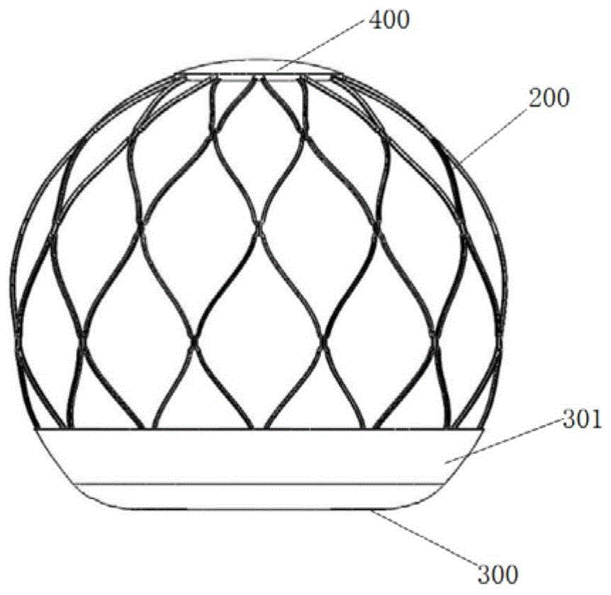
图3为本发明实施例一提供的二尖瓣返流治疗器械的示意图;3 is a schematic diagram of a mitral valve regurgitation treatment device provided in
图4为图3的仰视示意图;Fig. 4 is the bottom view schematic diagram of Fig. 3;
图5为本发明实施例一提供的二尖瓣返流治疗器械挡住二尖瓣反流位置的示意图;5 is a schematic diagram of a position where the mitral valve regurgitation treatment device blocks mitral valve regurgitation provided by
图6本发明实施例一提供的二尖瓣返流治疗器械的支架的示意图;6 is a schematic diagram of a stent for a mitral valve regurgitation treatment device provided in
图7本发明实施例一提供的二尖瓣返流治疗器械的支架设置连接接头的示意图;FIG. 7 is a schematic diagram of setting connecting joints on the stent of the mitral valve regurgitation treatment device provided in
图8为图3进一步改进的一种形式示意图;Fig. 8 is a schematic diagram of a further improved form of Fig. 3;
图9为图3进一步改进的另一种形式的示意图;Fig. 9 is a schematic diagram of another form of further improvement of Fig. 3;
图10为本发明实施例一提供的二尖瓣返流治疗器械的支架设置撑开部的示意图;10 is a schematic diagram of a stent provided with a spreader portion of the mitral valve regurgitation treatment device provided in
图11为图10连接底膜和顶膜的示意图;Figure 11 is a schematic diagram of Figure 10 connecting the bottom film and the top film;
图12为本发明实施例一提供的二尖瓣返流治疗器械设置凸出部的示意图;FIG. 12 is a schematic diagram of setting a protruding portion of a mitral valve regurgitation treatment device provided in
图13为不设置凸出部的二尖瓣返流治疗器械与图12形式的二尖瓣返流治疗器械设置在心脏上的状态对照图;Fig. 13 is a state comparison diagram of the mitral valve regurgitation treatment device without the protruding part and the mitral valve regurgitation treatment device in the form of Fig. 12 being installed on the heart;
图14为图12进一步改进的一种形式示意图;Fig. 14 is a schematic diagram of a further improved form of Fig. 12;
图15为图12进一步改进的另一种形式的示意图;Fig. 15 is a schematic diagram of another form further improved in Fig. 12;
图16为本发明实施例一提供的二尖瓣返流治疗器械的支架设置限位部的示意图;16 is a schematic diagram of a stent setting limit portion of a mitral valve regurgitation treatment device provided in
图17为图16形式的二尖瓣返流治疗器械设置在心脏内的状态示意图;FIG. 17 is a schematic view of the state in which the mitral valve regurgitation treatment device in the form of FIG. 16 is installed in the heart;
图18为本发明实施例一提供的二尖瓣返流治疗器械作为瓣中瓣手术辅助器械使用时的示意图;18 is a schematic diagram of the mitral valve regurgitation treatment device provided in the first embodiment of the present invention when it is used as an auxiliary device for valve-in-valve surgery;
图19为本发明实施例二提供的二尖瓣返流治疗器械的仰视示意图;19 is a schematic bottom view of the mitral valve regurgitation treatment device provided in Embodiment 2 of the present invention;
图20为本发明实施例二提供的二尖瓣返流治疗器械设置显影标记部的示意图;Fig. 20 is a schematic diagram of setting a developing marker portion of the mitral valve regurgitation treatment device provided in the second embodiment of the present invention;
图21为本发明实施例二提供的二尖瓣返流治疗器械挡住二尖瓣反流位置的示意图;FIG. 21 is a schematic diagram of a position where the mitral valve regurgitation treatment device blocks mitral valve regurgitation provided by Embodiment 2 of the present invention;
图22为本发明实施例三提供的二尖瓣返流治疗器械的仰视示意图;22 is a schematic bottom view of the mitral valve regurgitation treatment device provided in Embodiment 3 of the present invention;
图23本发明实施例三提供的二尖瓣返流治疗器械设置显影标记部的示意图;Fig. 23 is a schematic diagram of setting a developing marker portion of the mitral valve regurgitation treatment device provided in Embodiment 3 of the present invention;
图24为本发明实施例三提供的二尖瓣返流治疗器械挡住二尖瓣反流位置的示意图;24 is a schematic diagram of a position where the mitral valve regurgitation treatment device blocks mitral valve regurgitation provided by Embodiment 3 of the present invention;
图25为本发明实施例四提供的二尖瓣返流治疗器械的示意图;25 is a schematic diagram of a mitral valve regurgitation treatment device provided in Embodiment 4 of the present invention;
图26为图25的仰视示意图。FIG. 26 is a schematic bottom view of FIG. 25 .
图标:1-心脏;11-左心房;12-左心室;13-二尖瓣;14-左心耳;15-瓣中瓣;200-支架;201-平面端;210-限位部;220-撑开部;230-连接接头;240-凸出部;300-底膜;301-延伸部;310-通孔;320-显影标记部;400-顶膜;P1-第一反流位置;P2-第二反流位置;P3-第三反流位置。Icons: 1-heart; 11-left atrium; 12-left ventricle; 13-mitral valve; 14-left atrial appendage; 15-valve middle valve; 200-stent; 201-plane end; 230-connecting joint; 240-projecting part; 300-bottom film; 301-extension part; 310-through hole; 320-developing mark part; 400-top film; - 2nd regurgitation position; P3 - 3rd regurgitation position.
具体实施方式Detailed ways
下面将结合实施例对本发明的技术方案进行清楚、完整地描述,显然,所描述的实施例是本发明一部分实施例,而不是全部的实施例。基于本发明中的实施例,本领域普通技术人员在没有做出创造性劳动前提下所获得的所有其他实施例,都属于本发明保护的范围。The technical solutions of the present invention will be clearly and completely described below with reference to the embodiments. Obviously, the described embodiments are part of the embodiments of the present invention, but not all of the embodiments. Based on the embodiments of the present invention, all other embodiments obtained by those of ordinary skill in the art without creative efforts shall fall within the protection scope of the present invention.
实施例一Example 1
图1所示的是心脏1的二尖瓣13出现二尖瓣反流病变时的示意图。通常心脏1的二尖瓣13所在平面大致呈D型,其主要有三个位置容易出现反流,分别定义为第一反流位置P1、第二反流位置P2和第三反流位置P3,心脏1发生二尖瓣反流时,可能是三个反流位置均产生反流病变,也可能是其中的一个或两个反流位置产生反流病变。FIG. 1 is a schematic diagram showing a mitral valve regurgitation pathology in the
如图1~图18所示,本实施例提供一种二尖瓣返流治疗器械,用于过盈设置在左心房11内,包括支架200和底膜300,支架200为环形网格状结构,支架200用于接触二尖瓣13的一端(也即底端)具有呈平面设置的平面端201。底膜300覆盖在平面端201上,用于抵接在二尖瓣13靠近左心房11一侧的平面上,底膜300呈环形设置,底膜300的环形对应的通孔310用于供血液流动。As shown in FIGS. 1 to 18 , the present embodiment provides a mitral valve regurgitation treatment device, which is used to be arranged in the
其中,支架200为环形网格状结构,一般是大致球形的空心球状网格结构。器械的球状设计主要用于器械在左心房11位置的固定,器械通过一定的过盈量使之与左心房11产生支撑力,从而固定器械。环形网格状结构的支架200通常具有一定的变形自适应性能力,使得器械能够更好的适应左心房11的结构。并且为了方便器械通过微创手术植入,支架200可具有压缩状态和展开状态,在展开状态时,支架200为环形网格状结构;具体而言,支架200处于压缩状态时,器械可放置到相应的输送器内,通过输送器将器械输送到左心房11的位置,在到达左心房11位置时,将器械从输送器内推出,此时器械恢复至展开状态。支架200可以是记忆金属合金,具体可以是镍钛合金材料,整体设计采用软结构设计,使得器械能够更好的适应左心房11的结构,减少对原生心房结构以及相邻的主动脉的压迫。The
支架200底部的平面端201,可以起到承托底膜300的作用。底膜300至少能覆盖发生病变的反流位置,底膜300可以通过缝制、热塑等方式固定在支架200上。底膜300的材料可以选择硬的材料也可以选择软质的材料,具体可为高分子材料,例如PET(苯二甲酸与乙二醇的缩聚物),eTFP(乙烯-四氟乙烯共聚物);也可以是动物心包性的一种或多种材料。在本实施例中,平面端201为圆环形平面,底膜300呈圆环形设置,且底膜300上的通孔310与底膜300同心设置,底膜300的直径大于二尖瓣13的直径,以能够覆盖三个反流位置。The
另外,中心的通孔310的面积同常要大于4.0cm2(平方厘米),以避免术后患者发生二尖瓣狭窄的风险。In addition, the area of the central through
本实施例提供的二尖瓣返流治疗器械主要用于治疗脱垂性质的二尖瓣反流。在使用时,如图2所示,二尖瓣返流治疗器械完全释放在左心房11内,通过其和左心房11之间产生的相互作用力实现固定。The mitral valve regurgitation treatment device provided in this embodiment is mainly used for the treatment of prolapsed mitral valve regurgitation. When in use, as shown in FIG. 2 , the mitral valve regurgitation treatment device is completely released in the
器械的主体支架200为球状的网格结构,支架200的底部与二尖瓣13平面接触的部分为平面结构,也即平面端201为平面结构,平面端201上设置有底膜300,底膜300上有通孔310,可以保证血流流过。主要通过器械底部的平面端201结合底膜300防止瓣叶关闭时,瓣叶自由边突入左心房11,从而造成反流,其治疗原理如图2所示。The
本实施例二尖瓣返流治疗器械的与二尖瓣13平面接触的支架200的平面端201相当于圆形平面结构,且圆形平面中心位置有一个圆形的通孔310,通孔310和平面端201为同心圆。圆环形的底膜300相当于覆盖在通孔310和平面端201之间,通孔310和平面端201之间的底膜300能够在二尖瓣13处于关闭时挡住二尖瓣反流位置,如图5所示。其中,图5的a表示的是第一反流位置P1和第三反流位置P3发生反流病变时的覆盖示意图;图5的b表示的是第二反流位置P2发生反流病变时的示意图。由于本实施例二尖瓣返流治疗器械是完全对称的,所以释放时,无需在左心房11内部调整位置,减少操作难度。The
相比现有技术需要非介入性置换瓣膜或通过夹住瓣膜叶片等对瓣膜进行修复的方式,本实施例二尖瓣返流治疗器械通过挡住二尖瓣反流位置治疗二尖瓣反流,操作难度较低,有效解决了对医生团队和设备要求高的问题,对瓣膜几乎没有伤害;同时在左心房11内部撑开固定的方式,避免了现有瓣膜置换固定过程对瓣下组织破坏和流出道阻挡的风险,极大的提高了器械的安全性;器械在底部设有通孔310,既能保证限制脱垂治疗反流的作用,也完整的保留了患者原生的瓣下结构,同时,通孔310设计还能够为瓣中瓣技术提供便利。Compared with the prior art that requires non-invasive replacement of the valve or repairs the valve by clamping the valve leaflets, the mitral valve regurgitation treatment device of this embodiment treats mitral valve regurgitation by blocking the position of the mitral valve regurgitation, The operation difficulty is low, which effectively solves the problem of high requirements for the doctor team and equipment, and does almost no damage to the valve; at the same time, the method of spreading and fixing inside the
本实施例二尖瓣返流治疗器械的固定采用了球状的网格状的支架200,通过一定的植入过盈量保证器械整体在左心房11的固定,具体的支架200可通过镍钛合金一体激光雕刻而成。进一步地,支架200用于接触二尖瓣13的一端或该端的相对端设置有连接接头230,连接接头230用于与输送器连接。In this embodiment, the mitral valve regurgitation treatment device is fixed by a spherical grid-shaped
具体的,如图7所示支架200的球状网格的上端和下端均设计有与输送器连接的连接接头230,可实现器械经心尖和经心房间隔的释放方式。具体在使用输送器时,选择上端和下端两者中的其中一者的连接接头230与输送器连接,其中,选择上端的连接接头230与输送器连接时,通常器械是经过血管输送到左心房11内;选择下端的连接接头230与输送器连接时,通常器械是经过心尖输送到左心房11内。Specifically, as shown in FIG. 7 , the upper and lower ends of the spherical grid of the
如图6所示,在本实施例中,平面端201为支架200向内延伸形成的环形平面。其中,底膜300可以是覆盖在支架200上的一层也可是两层膜或更多层膜。具体的,本实施例底膜为双层膜,两层膜的周向边缘密封设置,以使相邻两层膜之间形成密封空间,环形平面穿设在底膜300的相邻两层膜之间。相当于相邻底膜300从环形平面的中间开口位置向外周延伸,将环形平面包覆在底膜300的两层膜之间,也即,支架200的平面端201的内、外侧各设置一层膜,内外侧的膜在周向的边缘密封连接,以形成密封空间。As shown in FIG. 6 , in this embodiment, the
可以理解的是,底膜300的材质通常具有流体渗透性,底膜300的多层膜之间为中空的密封结构,用于形成血栓,一方面使原来软结构的底膜300能够因为血栓形成而自行加固,起到更好的阻挡反流的作用,另一方面,也可以在器械底端与血液接触的平面自然形成光滑的流体冲刷面,减少血液滞留和局部湍流产生。It can be understood that the material of the
为了使得相邻的底膜300的相邻膜层之间的密封空间在支架200展开时自动增大,作为一个优选实现方式,支架200的内侧面靠近平面端201的位置,并与平面端201间隔设置有撑开部220,底膜300套设在平面端201与撑开部220之间。In order to automatically increase the sealing space between the adjacent film layers of the
具体的,如图10和图11所示,撑开部220相当于支架200上面设置的向内的倒钩。以底膜300为两层为例,上层的底膜300固定在倒钩上,下层的底膜300固定在平面端201上,从而在支架200撑开时,由于倒钩与平面端201之间的间隔,使得在底膜300撑开时,底膜300的两层膜之间的密封空间增大。Specifically, as shown in FIGS. 10 and 11 , the
可以理解的是,底膜300的较大的密封空间,更加有利于血栓的形成。It can be understood that the larger sealing space of the
进一步地,本实施例二尖瓣返流治疗器械的支架200用于远离二尖瓣13的一端覆盖有顶膜400。也即,如图3所示,器械的上端设置顶膜400,顶膜400的材质与底膜300的材质相同,且顶膜400也采用双层或双层以上的膜结构。Further, the end of the
顶膜400用于限制支架200的上端自由端的运动,防止自由端刺破左心房11,同时能够促进器械在上端与左心房11内皮化,固定瓣膜。The
作为本实施例的一个进一步的实现方式,如图3所示,底膜300在支架200上向远离二尖瓣13的一端延伸有延伸部301,也即器械底部的底膜300距离底面需要有一定的高度,该高度可以低于左心耳14高度,高度值为4-10毫米,以促进器械与左心房11快速内皮化,实现有效固定。As a further implementation of this embodiment, as shown in FIG. 3 , the
需要说明的是,延伸部301也可高于左心耳14的高度。具体可以是如图8所示的,延伸部301整体高于左心耳14,高出的部分是完全对称的;也可以是如图9所示的,延伸部301对应左心耳14位置的局部高于左心耳14,其他部分低于左心耳14,高出的部分是不对称设置。在另一种可实现的方式中,底膜300还可以向上延伸至与顶膜400连接为一体,也即整个支架200上均包覆覆膜,支架200被包覆在覆膜内。覆膜可以是一体构造,覆膜靠近接触二尖瓣13的一端形成底膜300,另一端作为顶膜400。It should be noted that the
可以理解的是,器械的底膜300设置较高,可以完全盖过左心耳14,实现左心房11封堵,能够有效防止房颤的产生。It can be understood that, the
进一步地,器械的底面可以有一定的高度(图15),对于有高度的底面结构,可以使器械突入左心室12的部分形成和被限制的局部原生瓣叶相适应的结构,增加贴合度,可以将被限制的原生瓣叶内皮化。Further, the bottom surface of the device can have a certain height (Fig. 15). For the bottom surface structure with a height, the part of the device protruding into the
具体的,如图12、图14和图15所示,本实施例支架200用于接触二尖瓣13的一端沿支架200的轴向向二尖瓣13所在的位置凸出有凸出部240,凸出部240的底端形成平面端201,底膜300覆盖在凸出部240上,并沿支架200向上延伸。Specifically, as shown in FIG. 12 , FIG. 14 and FIG. 15 , one end of the
需要说明的而是,凸出部240也可由底膜300在平面端201上面向二尖瓣13所在的位置形成,具体的底膜300可以是具有一定厚度的膜结构,具有一定厚度的膜结构覆盖在平面端201上,相当于平面端201面向二尖瓣13所在的位置凸出形成凸出部240。It should be noted that the protruding
其中,图13的a所示的是,没有凸出部240的二尖瓣返流治疗器械,图13的b所示的是图12所示的具有凸出部240的二尖瓣反流治疗器械,对比可知,具有凸出部240的二尖瓣反流治疗器械可以使器械突入左心室12部分形成和被限制的局部原生瓣叶相适应的结构,增加了贴合度。Among them, what is shown in FIG. 13 a is the mitral valve regurgitation treatment device without the protruding
同时,需要说明的是,如图14和图15所示,凸出部240的高度方向可以有一定的倾斜角度,也即凸出部240的侧面相对底端倾斜设置。倾斜设置的凸出部240更加有利于使器械突入左心室12部分形成和被限制的局部原生瓣叶相适应的结构。Meanwhile, it should be noted that, as shown in FIG. 14 and FIG. 15 , the height direction of the protruding
进一步的,为了避免器械在左心房11内的转动,本实施例二尖瓣返流治疗器械的支架200的外侧面靠近平面端201的位置凸出有限位部210,限位部210用于限制支架200的周向转动。Further, in order to avoid the rotation of the device in the
如图16和图17所示,支架200底部位置可设置倒刺,作为限位部210,由于远离底面的较远处的左心房11比较薄,所以过高的倒刺位置或是过长的倒刺会增加刺破心房壁的风险,故倒刺位于距离器械底面0-4毫米位置,倒刺长度为0.5-2毫米左右。倒刺等形式的限位部210可以帮助器械实现固定,减小器械发生周向转动的风险。As shown in FIG. 16 and FIG. 17 , barbs can be provided at the bottom of the
如图18所示,本实施例二尖瓣返流治疗器械的底膜300上的通孔310的孔径优选设计为20-29毫米,如果患者再次反流,可以为患者进行瓣中瓣15的手术。也即在进行瓣中瓣15的手术时,本实施例二尖瓣返流治疗器械可以作为锚固机构。As shown in FIG. 18 , the diameter of the through
实施例二Embodiment 2
为了增加通孔310的面积,以增加手术治疗后患者的有效瓣口面积,减低跨瓣压差,如图19~图21所示,本实施例二尖瓣返流治疗器械区别于实施例一,将通孔310设置为偏心的圆孔,也即底膜300与通孔310偏心设置。In order to increase the area of the through
偏心的圆孔可以设置在远离病变反流位置的一侧,进而可以增加通孔310的面积,以加大有效瓣口面积和减小跨瓣压差,同时对于不同反流位置(第一反流位置P1、第二反流位置P2、第三反流位置P3)由于脱垂而导致的反流,可以通过释放过程中,转动器械的释放角度以实现反流的治疗,具体如图21所示。其中图21的a表示的是第二反流位置P2发生病变的治疗示意图,图21的b表示的是第三反流位置P3发生病变的治疗示意图,图21的c表示的是第一反流位置P1发生病变的治疗示意图。图21的b和图24的c的箭头表示的是器械可以沿该方向转动。The eccentric circular hole can be set on the side away from the pathological regurgitation position, and then the area of the through
优选的,通孔310与底膜300的圆形边缘相切设置,以最大限度的增大通孔310的面积。Preferably, the through
由于偏心通孔310的形式,在器械植入时需要绕轴向旋转其角度,以保证治疗不同位置的反流,所以为了方便观察位置并方便操作,底膜300或平面端201上设置有显影标记部320,以保证器械能够准确释放。具体的,如图20所示,本实施例显影标记部320可以是显影点,其设置在底膜300的外边缘上,显影点设置有3个,其中一个显影点位于底膜300的圆心与切点的连线上,并位于远离切点的一侧,另两个显影线位于与该连线垂直且通过底膜300圆心的直线上。Due to the form of the eccentric through
本实施例二尖瓣返流治疗器械的其他结构可采用与实施例一提供的二尖瓣返流治疗器械相同的结构,在此不再赘述。且本实施例二尖瓣返流治疗器械与实施例一提供的二尖瓣返流治疗器械具有相同的有益效果。Other structures of the device for treating mitral valve regurgitation in this embodiment can be the same as those of the device for treating mitral valve regurgitation provided in the first embodiment, which will not be repeated here. In addition, the mitral valve regurgitation treatment device of this embodiment has the same beneficial effects as the mitral valve regurgitation treatment device provided in the first embodiment.
实施例三Embodiment 3
为了增加通孔310的面积,以增加手术治疗后患者的有效瓣口面积,减低跨瓣压差,如图22~图24所示,本实施例二尖瓣返流治疗器械区别于实施例一和实施例二,将通孔310设置为椭圆形。In order to increase the area of the through
优选的,通孔310为与底膜300偏心的椭圆形,且通孔310的椭圆形的短边侧与底膜300的边缘相切设置。Preferably, the through
本实施例二尖瓣返流治疗器械与实施例二类似,可以通过旋转实施不同位置由脱垂而引起的反流,具体如图24所示。其中图24的a表示对是第二反流位置P2发生病变时的治疗示意图;图24的b表示的是第三反流位置P3发生病变时的治疗示意图;图24的c表示的是第一反流位置P1发生病变时的治疗示意图。图24的b和图24的c的箭头表示的是器械可以沿该方向转动。The mitral valve regurgitation treatment device in this embodiment is similar to that in the second embodiment, and can be rotated to implement regurgitation caused by prolapse at different positions, as shown in FIG. 24 . Wherein a of Fig. 24 shows a schematic diagram of the treatment when the second reflux position P2 has a lesion; b of Fig. 24 shows a schematic diagram of the treatment when a lesion occurs at the third reflux position P3; c of Fig. 24 shows the first Schematic diagram of the treatment in the event of a lesion at the reflux site P1. The arrows in Fig. 24 b and Fig. 24 c indicate that the instrument can be rotated in this direction.
如图23所示,由于椭圆形的通孔310的形式,在器械植入时需要绕轴向旋转其角度,以保证治疗不同位置的反流,所以为了方便观察位置并方便操作,在本实施例中,底膜300或平面端201上也设置有显影标记部320,以保证器械能够准确释放。具体显影标记部320的设置位置可参照实施例二的描述。As shown in FIG. 23, due to the form of the oval through
可以理解的是,偏心的椭圆形的通孔310,相比实施例二的方式,可以进一步增加通孔310的面积,以增加手术治疗后患者的有效瓣口面积,减低跨瓣压差。It can be understood that the eccentric elliptical through
本实施例二尖瓣返流治疗器械的其他结构可采用与实施例一提供的二尖瓣返流治疗器械相同的结构,在此不再赘述。且本实施例二尖瓣返流治疗器械与实施例一提供的二尖瓣返流治疗器械具有相同的有益效果。Other structures of the device for treating mitral valve regurgitation in this embodiment can be the same as those of the device for treating mitral valve regurgitation provided in the first embodiment, which will not be repeated here. In addition, the mitral valve regurgitation treatment device of this embodiment has the same beneficial effects as the mitral valve regurgitation treatment device provided in the first embodiment.
实施例四Embodiment 4
如图25和图26所示,本实施例二尖瓣返流治疗器械区别于实施例一、实施例二和实施例三,底膜300设置为D型环,对应的通孔310设置为D型孔。As shown in FIG. 25 and FIG. 26 , the mitral valve regurgitation treatment device of this embodiment is different from
可以理解的是,D型底膜300更加符合二尖瓣13的结构特点,可以节约底膜300的材料,但是制作工艺略微复杂。It can be understood that, the D-shaped
本实施例二尖瓣返流治疗器械的其他结构可采用与实施例一提供的二尖瓣返流治疗器械相同的结构,在此不再赘述。且本实施例二尖瓣返流治疗器械与实施例一提供的二尖瓣返流治疗器械具有相同的有益效果。Other structures of the device for treating mitral valve regurgitation in this embodiment can be the same as those of the device for treating mitral valve regurgitation provided in the first embodiment, which will not be repeated here. In addition, the mitral valve regurgitation treatment device of this embodiment has the same beneficial effects as the mitral valve regurgitation treatment device provided in the first embodiment.
最后应说明的是:以上各实施例仅用以说明本发明的技术方案,而非对其限制;尽管参照前述各实施例对本发明进行了详细的说明,本领域的普通技术人员应当理解:其依然可以对前述各实施例所记载的技术方案进行修改,或者对其中部分或者全部技术特征进行等同替换;而这些修改或者替换,并不使相应技术方案的本质脱离本发明各实施例技术方案的范围。Finally, it should be noted that the above embodiments are only used to illustrate the technical solutions of the present invention, but not to limit them; although the present invention has been described in detail with reference to the foregoing embodiments, those of ordinary skill in the art should understand that: The technical solutions described in the foregoing embodiments can still be modified, or some or all of the technical features thereof can be equivalently replaced; and these modifications or replacements do not make the essence of the corresponding technical solutions deviate from the technical solutions of the embodiments of the present invention. scope.
Claims (17)
Priority Applications (1)
| Application Number | Priority Date | Filing Date | Title |
|---|---|---|---|
| CN202011147001.0A CN112137762A (en) | 2020-10-23 | 2020-10-23 | Mitral regurgitation treatment device |
Applications Claiming Priority (1)
| Application Number | Priority Date | Filing Date | Title |
|---|---|---|---|
| CN202011147001.0A CN112137762A (en) | 2020-10-23 | 2020-10-23 | Mitral regurgitation treatment device |
Publications (1)
| Publication Number | Publication Date |
|---|---|
| CN112137762A true CN112137762A (en) | 2020-12-29 |
Family
ID=73954716
Family Applications (1)
| Application Number | Title | Priority Date | Filing Date |
|---|---|---|---|
| CN202011147001.0A Pending CN112137762A (en) | 2020-10-23 | 2020-10-23 | Mitral regurgitation treatment device |
Country Status (1)
| Country | Link |
|---|---|
| CN (1) | CN112137762A (en) |
Cited By (2)
| Publication number | Priority date | Publication date | Assignee | Title |
|---|---|---|---|---|
| CN115105264A (en) * | 2021-07-12 | 2022-09-27 | 上海易桥医疗器械有限公司 | Valve stent and valve prosthesis system |
| CN116549183A (en) * | 2023-05-05 | 2023-08-08 | 张晨朝 | Interventional valve repair bracket |
Citations (6)
| Publication number | Priority date | Publication date | Assignee | Title |
|---|---|---|---|---|
| CN105455924A (en) * | 2014-09-26 | 2016-04-06 | Nvt股份公司 | Implantable device for treating mitral valve regurgitation |
| CN109009569A (en) * | 2018-09-07 | 2018-12-18 | 谭雄进 | A kind of artificial mitral valve intervention displacement apparatus and its interventional method |
| CN110279495A (en) * | 2019-06-25 | 2019-09-27 | 陈翔 | A kind of self-expanding heart valve prosthesis |
| CN111698967A (en) * | 2018-02-12 | 2020-09-22 | 4C医学技术有限公司 | Expandable frame and paravalvular leak mitigation system for implantable prosthetic heart valve devices |
| US20200306043A1 (en) * | 2017-11-03 | 2020-10-01 | University Of Maryland, Baltimore | Valve translocation device and method for the treatment of functional valve regurgitation |
| CN213665979U (en) * | 2020-10-23 | 2021-07-13 | 上海丹领商务咨询事务所 | Mitral regurgitation therapeutic equipment |
-
2020
- 2020-10-23 CN CN202011147001.0A patent/CN112137762A/en active Pending
Patent Citations (6)
| Publication number | Priority date | Publication date | Assignee | Title |
|---|---|---|---|---|
| CN105455924A (en) * | 2014-09-26 | 2016-04-06 | Nvt股份公司 | Implantable device for treating mitral valve regurgitation |
| US20200306043A1 (en) * | 2017-11-03 | 2020-10-01 | University Of Maryland, Baltimore | Valve translocation device and method for the treatment of functional valve regurgitation |
| CN111698967A (en) * | 2018-02-12 | 2020-09-22 | 4C医学技术有限公司 | Expandable frame and paravalvular leak mitigation system for implantable prosthetic heart valve devices |
| CN109009569A (en) * | 2018-09-07 | 2018-12-18 | 谭雄进 | A kind of artificial mitral valve intervention displacement apparatus and its interventional method |
| CN110279495A (en) * | 2019-06-25 | 2019-09-27 | 陈翔 | A kind of self-expanding heart valve prosthesis |
| CN213665979U (en) * | 2020-10-23 | 2021-07-13 | 上海丹领商务咨询事务所 | Mitral regurgitation therapeutic equipment |
Cited By (3)
| Publication number | Priority date | Publication date | Assignee | Title |
|---|---|---|---|---|
| CN115105264A (en) * | 2021-07-12 | 2022-09-27 | 上海易桥医疗器械有限公司 | Valve stent and valve prosthesis system |
| CN115105264B (en) * | 2021-07-12 | 2025-10-24 | 上海易桥医疗器械有限公司 | Valve stents and valve prosthesis systems |
| CN116549183A (en) * | 2023-05-05 | 2023-08-08 | 张晨朝 | Interventional valve repair bracket |
Similar Documents
| Publication | Publication Date | Title |
|---|---|---|
| US12491068B2 (en) | Two stage anchor and mitral valve assembly | |
| US20250099247A1 (en) | Device, system, and method for transcatheter treatment of valve regurgitation | |
| JP6721770B2 (en) | Structural member for artificial mitral valve | |
| CN109414321B (en) | Device for treating valve regurgitation | |
| WO2018040244A1 (en) | Artificial cardiac valve | |
| JP6423787B2 (en) | Devices, systems, and methods for transcatheter treatment of valvular reflux | |
| CN105520792B (en) | A kind of D-shaped insertion type artificial cardiac valve | |
| US10449049B2 (en) | Prosthesis for preventing valve regurgitation | |
| US8216303B2 (en) | Apparatus and method for treating a regurgitant heart valve | |
| US10080659B1 (en) | Devices and methods for minimally invasive repair of heart valves | |
| CN102481189B (en) | Heart valve with anchoring structure with concave landing area | |
| JP6727218B2 (en) | System and method for heart valve therapy | |
| CN105726167A (en) | Involved artificial heart valve prosthesis | |
| US20140330371A1 (en) | Prosthetic valves and associated appartuses, systems and methods | |
| JP2016517748A (en) | Medical device and related methods for implantation in a valve | |
| AU2006237197A1 (en) | A blood flow controlling apparatus | |
| JP2004510493A (en) | Minimally invasive annuloplasty repair segment delivery template system | |
| CN112137762A (en) | Mitral regurgitation treatment device | |
| US20230414353A1 (en) | Transcatheter heart valve delivery system | |
| CN103300944A (en) | Seamless aortic valve replacement device | |
| CN205434002U (en) | Intervention formula artificial heart valve | |
| CN213665979U (en) | Mitral regurgitation therapeutic equipment | |
| CN113558822B (en) | An interventional mitral valve replacement system | |
| US20220304801A1 (en) | Prosthetic heart valve | |
| RU2670661C9 (en) | Method for production seal-containing conduite and seal-containing conduite |
Legal Events
| Date | Code | Title | Description |
|---|---|---|---|
| PB01 | Publication | ||
| PB01 | Publication | ||
| SE01 | Entry into force of request for substantive examination | ||
| SE01 | Entry into force of request for substantive examination | ||
| RJ01 | Rejection of invention patent application after publication | ||
| RJ01 | Rejection of invention patent application after publication |
Application publication date: 20201229 |