CN112078171A - Extruder orifice switch assembly and extruder including the same - Google Patents
Extruder orifice switch assembly and extruder including the same Download PDFInfo
- Publication number
- CN112078171A CN112078171A CN201910517220.4A CN201910517220A CN112078171A CN 112078171 A CN112078171 A CN 112078171A CN 201910517220 A CN201910517220 A CN 201910517220A CN 112078171 A CN112078171 A CN 112078171A
- Authority
- CN
- China
- Prior art keywords
- orifice plate
- plate
- frame
- orifice
- hole
- Prior art date
- Legal status (The legal status is an assumption and is not a legal conclusion. Google has not performed a legal analysis and makes no representation as to the accuracy of the status listed.)
- Pending
Links
Images


Classifications
-
- B—PERFORMING OPERATIONS; TRANSPORTING
- B30—PRESSES
- B30B—PRESSES IN GENERAL
- B30B11/00—Presses specially adapted for forming shaped articles from material in particulate or plastic state, e.g. briquetting presses, tabletting presses
- B30B11/22—Extrusion presses; Dies therefor
-
- B—PERFORMING OPERATIONS; TRANSPORTING
- B01—PHYSICAL OR CHEMICAL PROCESSES OR APPARATUS IN GENERAL
- B01J—CHEMICAL OR PHYSICAL PROCESSES, e.g. CATALYSIS OR COLLOID CHEMISTRY; THEIR RELEVANT APPARATUS
- B01J37/00—Processes, in general, for preparing catalysts; Processes, in general, for activation of catalysts
- B01J37/0009—Use of binding agents; Moulding; Pressing; Powdering; Granulating; Addition of materials ameliorating the mechanical properties of the product catalyst
-
- B—PERFORMING OPERATIONS; TRANSPORTING
- B30—PRESSES
- B30B—PRESSES IN GENERAL
- B30B15/00—Details of, or accessories for, presses; Auxiliary measures in connection with pressing
- B30B15/02—Dies; Inserts therefor; Mounting thereof; Moulds
- B30B15/028—Loading or unloading of dies, platens or press rams
Landscapes
- Chemical & Material Sciences (AREA)
- Engineering & Computer Science (AREA)
- Mechanical Engineering (AREA)
- Materials Engineering (AREA)
- Organic Chemistry (AREA)
- Chemical Kinetics & Catalysis (AREA)
- Extrusion Moulding Of Plastics Or The Like (AREA)
Abstract
本发明涉及催化剂载体制备装置领域,公开了一种挤条机孔板切换组件及包括其的挤条机。所述挤条机孔板切换组件包括支撑架(1)、限位结构、孔板架(3)以及位置切换动力源(5),限位结构包括限位板(2),该限位板连接在支撑架上并且设置有暴露孔(22),限位结构能够限制孔板架沿挤出方向移动,孔板架上设置有多个孔板(4),孔板上设置有多个挤条孔(41),暴露孔沿挤出方向暴露多个挤条孔,位置切换动力源与孔板架连接,位置切换动力源能够驱动孔板架沿预设方向移动,以切换孔板架上的多个孔板的位置。本发明单单通过移动孔板架就能够切换成新的孔板,从而更换孔板的操作非常快速方便。
The invention relates to the field of catalyst carrier preparation devices, and discloses an extruder orifice plate switching assembly and an extruder comprising the same. The orifice plate switching assembly of the extruder includes a support frame (1), a limit structure, an orifice plate frame (3) and a position switching power source (5), and the limit structure includes a limit plate (2), the limit plate The orifice plate is connected to the support frame and is provided with an exposure hole (22), the limiting structure can limit the movement of the orifice plate frame along the extrusion direction, the orifice plate frame is provided with a plurality of orifice plates (4), and the orifice plate is provided with a plurality of extruders. The strip hole (41), the exposing hole exposes a plurality of extruding strip holes along the extrusion direction, the position switching power source is connected with the orifice plate frame, and the position switching power source can drive the orifice plate frame to move along a preset direction, so as to switch the orifice plate frame position of multiple well plates. The present invention can switch to a new orifice plate simply by moving the orifice plate frame, so that the operation of replacing the orifice plate is very fast and convenient.
Description
技术领域technical field
本发明涉及催化剂载体制备装置领域,具体地涉及一种用于生产催化剂载体的挤条成型装置的挤条机孔板切换组件及包括其的挤条机。The invention relates to the field of catalyst carrier preparation devices, in particular to an extruder orifice switch assembly of an extruder molding device for producing catalyst carriers and an extruder comprising the same.
背景技术Background technique
在石油化工领域的催化剂载体的生产中,挤出成型法是工业上生产催化剂载体的重要方法。挤出成型法是将要造粒的粉体物料限定压缩在一定的空间中,通过外力压紧为密实状态,并通过一定的孔板模具形成预定的形状。此方法具有适应原料及环境的能力强、单台设备产量大、颗粒均匀度和颗粒强度好等优点。In the production of catalyst carriers in the petrochemical field, extrusion molding is an important method for industrially producing catalyst carriers. The extrusion molding method is to compress the powder material to be granulated in a certain space, press it into a dense state by external force, and form a predetermined shape through a certain orifice die. This method has the advantages of strong ability to adapt to raw materials and environment, large output of single equipment, good particle uniformity and particle strength.
挤条机是挤出成型法中主要使用的设备,在应用挤条机生产催化剂载体时,特别是生产异型载体时,挤条机多孔板内成型模具经常堵塞,需要拆卸孔板清理更换成型模具。目前,挤条机机头与多孔板的之间多为螺栓紧固连接,人工拆装更换多孔板的过程劳动强度大、耗费时间长,影响载体成型设备的生产效率。The extruder is the main equipment used in the extrusion molding method. When the extruder is used to produce catalyst carriers, especially when producing special-shaped carriers, the molding die in the perforated plate of the extruder is often blocked, and the orifice plate needs to be removed to clean and replace the molding die. . At present, the head of the extruder and the perforated plate are mostly connected by bolts. The manual disassembly and replacement of the perforated plate is labor-intensive and time-consuming, which affects the production efficiency of the carrier forming equipment.
针对现有技术的不足之处,需要一种能够在催化剂载体挤条过程中快速更换孔板的方法,以弥补现有技术的不足。In view of the deficiencies of the prior art, a method for quickly replacing the orifice plate during the extrusion process of the catalyst carrier is required to make up for the deficiencies of the prior art.
发明内容SUMMARY OF THE INVENTION
本发明的目的是提供一种能够在催化剂载体挤条过程中快速更换孔板的挤条机孔板切换组件及包括其的挤条机。The purpose of the present invention is to provide an extruder orifice plate switching assembly capable of rapidly changing the orifice plate during the catalyst carrier extrusion process and an extruder including the same.
为了实现上述目的,本发明一方面提供一种挤条机孔板切换组件,所述挤条机孔板切换组件包括支撑架、限位结构、孔板架以及位置切换动力源,所述限位结构包括限位板,该限位板连接在所述支撑架上并且设置有暴露孔,所述限位结构能够限制所述孔板架沿挤出方向移动,所述孔板架上设置有多个孔板,所述孔板上设置有多个挤条孔,所述暴露孔沿所述挤出方向暴露所述多个挤条孔,所述位置切换动力源与所述孔板架连接,所述位置切换动力源能够驱动所述孔板架沿预设方向移动,以切换所述孔板架上的多个所述孔板的位置。In order to achieve the above object, one aspect of the present invention provides an extruder orifice plate switching assembly, the extruder orifice plate switching assembly includes a support frame, a limit structure, an orifice plate frame and a position switching power source, the limit The structure includes a limit plate, the limit plate is connected to the support frame and is provided with an exposed hole, the limit structure can limit the movement of the orifice plate frame along the extrusion direction, and the orifice plate frame is provided with a plurality of an orifice plate, the orifice plate is provided with a plurality of extrusion holes, the exposing holes expose the plurality of extrusion holes along the extrusion direction, and the position switching power source is connected to the orifice plate frame, The position switching power source can drive the orifice plate frame to move in a preset direction, so as to switch the positions of the plurality of orifice plates on the orifice plate frame.
优选地,所述限位结构还包括限位动力源和与所述限位动力源连接的驱动杆,所述限位板上还设置有驱动孔,所述驱动杆穿设于所述驱动孔以对所述孔板架施加压力或解除压力。Preferably, the limiting structure further includes a limiting power source and a driving rod connected with the limiting power source, a driving hole is further provided on the limiting plate, and the driving rod is penetrated through the driving hole to apply or release pressure to the orifice plate holder.
优选地,所述限位动力源设置有多个,所述驱动孔与所述驱动杆的数量对应地设置有多个。Preferably, a plurality of the limiting power sources are provided, and a plurality of the driving holes are provided corresponding to the number of the driving rods.
优选地,所述位置切换动力源和所述限位动力源为液压缸。Preferably, the position switching power source and the limit power source are hydraulic cylinders.
优选地,所述支撑架和所述限位板之间形成有容纳空间,所述孔板架位于所述容纳空间中,所述驱动杆可伸入所述容纳空间以对所述孔板架施加压力或可从所述容纳空间伸出以解除对所述孔板架的压力。Preferably, an accommodating space is formed between the support frame and the limiting plate, the orifice plate frame is located in the accommodating space, and the driving rod can extend into the accommodating space to connect the orifice plate frame to the accommodating space. Pressure is applied or can be extended from the receiving space to relieve pressure on the orifice plate holder.
优选地,所述支撑架上设置有沿所述预设方向延伸的导轨,所述孔板架可滑动地连接于所述导轨。Preferably, the support frame is provided with a guide rail extending along the preset direction, and the orifice plate frame is slidably connected to the guide rail.
优选地,所述限位结构还包括设置于所述导轨和所述限位板之间的限位块。Preferably, the limiting structure further includes a limiting block disposed between the guide rail and the limiting plate.
优选地,所述挤条机孔板切换组件还包括沿所述预设方向延伸的导向杆,该导向杆的一端连接在所述孔板架上,另一端插入在形成于所述支撑架上的引导孔中。Preferably, the extruder orifice plate switching assembly further includes a guide rod extending along the preset direction, one end of the guide rod is connected to the orifice plate frame, and the other end of the guide rod is inserted into the support frame formed on the in the guide hole.
优选地,所述孔板上的所述多个挤条孔的开孔布局形状为圆环状。Preferably, the shape of the openings of the plurality of extruded holes on the orifice plate is annular.
本发明的另一方面提供一种挤条机,所述挤条机包括机头和如上所述的挤条机孔板切换组件,所述机头与所述支撑架连接,并且所述机头的物料出口与所述孔板对齐。Another aspect of the present invention provides an extruder, the extruder includes a head and the extruder orifice switch assembly as described above, the head is connected with the support frame, and the head is The material outlet is aligned with the orifice plate.
通过上述技术方案,当需要更换孔板时,启动位置切换动力源,驱动孔板架沿预设方向移动,最终孔板架移动至孔板架上的未使用过的孔板位于挤条机的物料出口处,由于本发明的孔板架上设置有多个孔板,单单通过移动孔板架就能够切换成新的孔板,从而与以往孔板与挤条机螺栓连接的结构相比,更换孔板的操作非常快速方便。本发明的优点将在下面的具体实施方式中更加详细地说明。Through the above technical solution, when the orifice plate needs to be replaced, the power source is switched on at the start position, and the orifice plate frame is driven to move in the preset direction, and finally the orifice plate frame moves to the unused orifice plate on the orifice plate frame, which is located in the position of the extruder. At the material outlet, since the orifice plate frame of the present invention is provided with a plurality of orifice plates, the orifice plate frame can be switched to a new orifice plate only by moving the orifice plate frame. Replacing the orifice plate is quick and easy. The advantages of the present invention will be explained in more detail in the following detailed description.
附图说明Description of drawings
附图是用来提供对本发明的进一步理解,并且构成说明书的一部分,与下面的具体实施方式一起用于解释本发明,但并不构成对本发明的限制。在附图中:The accompanying drawings are used to provide a further understanding of the present invention, and constitute a part of the specification, and together with the following specific embodiments, are used to explain the present invention, but do not constitute a limitation to the present invention. In the attached image:
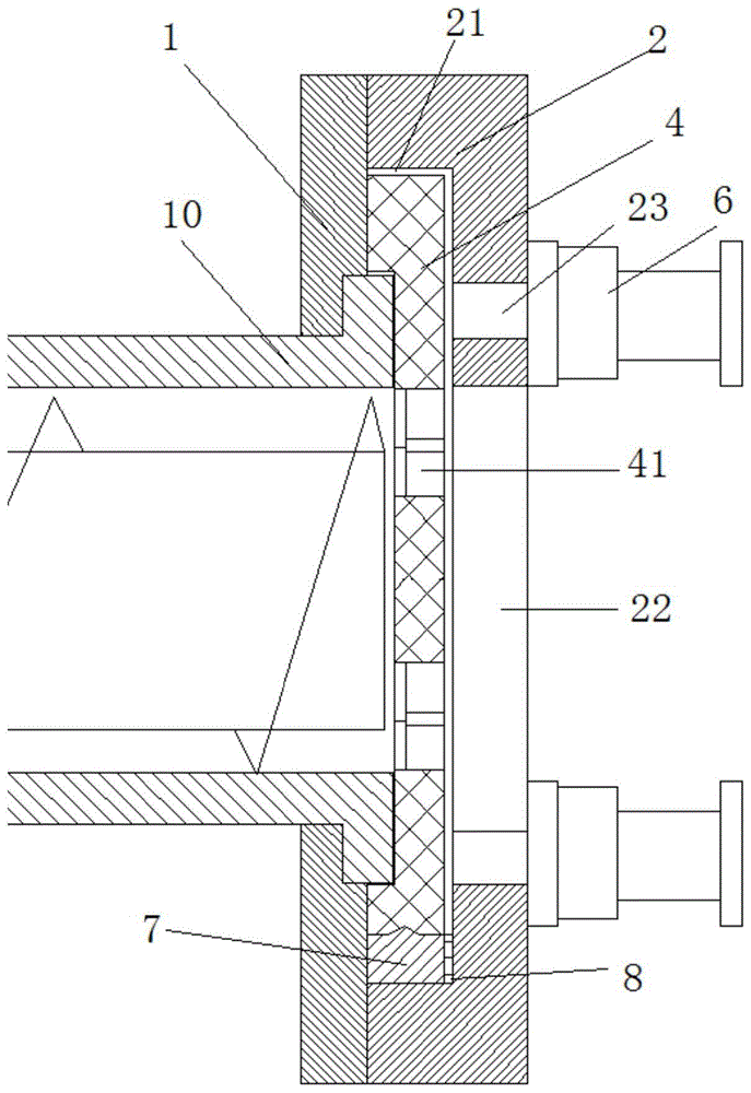
图1是本发明提供的挤条机孔板切换组件的主视示意图;1 is a schematic front view of an extruder orifice plate switching assembly provided by the present invention;
图2是本发明提供的挤条机孔板切换组件的俯视示意图;2 is a schematic top view of the extruder orifice plate switching assembly provided by the present invention;
图3是本发明提供的挤条机的侧部剖视示意图。FIG. 3 is a schematic side sectional view of the extruder provided by the present invention.
附图标记说明Description of reference numerals
1支撑架 2限位板1 Support frame 2 Limit plate
21容纳空间 22暴露孔21 Accommodating
23驱动孔 3孔板架23-drive hole 3-well plate holder
4孔板 41挤条孔4-well plate with 41 extruded holes
5位置切换动力源 6限位动力源5-position switching power source 6-position limit power source
7导轨 8限位块7
9导向杆 10机头9
11液压系统11 Hydraulic system
具体实施方式Detailed ways
以下,参照附图,详细说明本发明的优选实施方式如下。另外,在说明本发明时,在判断出针对相关的公知功能或结构的说明可能会不必要地混淆本发明的主旨的情况下,将省略对其的具体说明。Hereinafter, preferred embodiments of the present invention will be described in detail with reference to the accompanying drawings. In addition, in describing the present invention, if it is judged that the description of related well-known functions or configurations may unnecessarily obscure the gist of the present invention, the detailed description thereof will be omitted.
如图1至图3所示,本发明提供一种挤条机孔板切换组件。本发明提供的挤条机孔板切换组件包括支撑架1、限位结构、孔板架3以及位置切换动力源5。As shown in Fig. 1 to Fig. 3, the present invention provides an extruder orifice plate switching assembly. The orifice plate switching assembly of the extruder provided by the present invention includes a
如图1所示,支撑架1是挤条机孔板切换组件的基础支撑部件,为各个部件提供安装基础,并且该支撑架1用于连接挤条机孔板切换组件和挤条机的机头(下面将详细说明)。另外,支撑架1的形状可以根据具体需要进行设计即可,支撑架1的材料优选采用硬度大的材料。As shown in Figure 1, the
限位结构是限制孔板架3沿挤出方向移动的部件。限位结构包括限位板2,该限位板2连接在支撑架1上,限位板2为了限制孔板架3沿挤出方向移动,需要设置在与挤条机相对的位置上,使得孔板位于挤条机和限位板2之间,同时为了使催化剂能够沿挤出方向挤出,在限位板2上还设置有暴露孔22,该暴露孔22与孔板对齐设置,且暴露孔22沿挤出方向暴露下述的多个挤条孔41。The limiting structure is a component that restricts the movement of the
孔板架3是用于安装多个孔板4的部件,其上设置有多个孔板4,孔板4上设置有多个挤条孔41。在图1和图2中示出了孔板架3上沿左右方向间隔布置有两个孔板4,且两个孔板4分别一体形成在孔板架3上,但是孔板4的布置形式及个数等不限于此,多个孔板4可以圆形布置,也可以上下左右排列布置,多个孔板4也可以是可拆卸地设置于孔板架3,孔板4的具体形式根据具体需要进行设计即可。孔板4上的多个挤条孔41的布置形式和个数也可以根据具体需要进行设计即可,在本发明中,如图1所示,作为优选实施方式,孔板4上的多个挤条孔41的开孔布局形状为圆环状,且在径向方向上布置有两个环,但本发明不限于此。在实际工况中,在挤条孔中会设置有成型模具,成型模具为具有一定厚度的圆盘状,其面板上沿厚度方向形成有多个孔,该孔的形状可以是多孔柱型、三叶草型或齿球型或其他结构,根据实际需要选择使用即可。The
位置切换动力源5是向孔板架3提供动力的部件,位置切换动力源5与孔板架3连接,其能够驱动孔板架3沿预设方向移动,以切换孔板架3上的多个孔板4的位置。如上所述,多个孔板4可以圆形布置,此时位置切换动力源5可以是使孔板架3旋转的动力源,多个孔板4也可以是上下左右排列布置,此时位置切换动力源5可以包括使孔板架3沿左右移动的左右驱动动力源和使孔板架3沿上下方向移动的上下驱动动力源,具体形式根据具体需要进行设计即可。总之,位置切换动力源5能够使孔板架3移动,从而使孔板架3上的未使用过的孔板4位于挤条机的物料出口处即可。The position switching
在工作状态(孔板位于工作位置)下,挤条机的物料出口、孔板4以及限位板2的暴露孔22处于对齐状态,从挤条机的物料出口挤出物料,物料经过孔板4之后,被挤出成条状催化剂。当需要更换孔板4时,先使挤条机停机,然后启动位置切换动力源5并驱动孔板架3沿预设方向移动,最终使孔板架3上的新的孔板4位于工作位置,从而完成孔板的更换。In the working state (the orifice plate is in the working position), the material outlet of the extruder, the orifice plate 4 and the exposed
由于本发明的挤条机孔板切换组件的孔板4与挤条机之间没有直接连接,而是通过限位结构来限制孔板4沿挤出方向移动,限位结构能够保持孔板4在挤条过程中不沿挤出方向移动,由此可见,本发明的挤条机孔板切换组件能够非常快速地更换孔板4,与以往的挤条机机头与多孔板螺栓紧固连接的技术相比,没有人工拆装更换多孔板的过程,劳动强度大大减少,孔板更换时间缩短,整体提高了催化剂载体成型设备的生产效率。Because the orifice plate 4 of the extruder orifice plate switching assembly of the present invention is not directly connected to the extruder, but the orifice plate 4 is restricted from moving along the extrusion direction by the limit structure, which can keep the orifice plate 4 It does not move in the extrusion direction during the extrusion process. It can be seen that the orifice plate switching assembly of the extruder of the present invention can replace the orifice plate 4 very quickly, and is bolted to the former extruder head and the perforated plate. Compared with the conventional technology, there is no manual disassembly and replacement process of the porous plate, the labor intensity is greatly reduced, the replacement time of the orifice plate is shortened, and the production efficiency of the catalyst carrier molding equipment is improved as a whole.
关于限位结构,可以仅通过限位板2来限制孔板架3在挤出方向上的移动,即,孔板架3和限位板2之间的间隙设置成非常小,既能够实现孔板架3沿左右方向移动,又在挤出方向的移动微乎其微,但作为优选实施方式,如图1至图3所示,限位结构还可以包括限位动力源6和与限位动力源6连接的驱动杆,限位板2上还设置有驱动孔23,驱动杆穿设于驱动孔23以对孔板架3施加压力或解除压力。通过驱动杆直接在孔板架3上施压,直接抵抗挤出压力。Regarding the limiting structure, the movement of the
位置切换动力源5和限位动力源6的优选实施方式,本发明中选用了液压缸,位置切换动力源5采用一个大液压缸与孔板架3的一边固定连接,限位动力源6采用多个小液压缸可与孔板架3接触连接,从而对孔板架3可以施加压力或解除压力。优选地,限位动力源6设置有多个,驱动孔23与驱动杆的数量对应地设置有多个,但本发明不限于此,只要能够向孔板架3提供足够的压力而防止孔板架3沿挤出方向移动即可。在图1至图2中,示出了3个小液压缸用作限位动力源6。A preferred embodiment of the position switching
具体地,大液压缸(位置切换动力源5)的活塞杆与孔板架3的一边固定连接,从而孔板架3能够根据大液压缸的活塞杆的移动而移动。如图1所示,当孔板架3上设置有两个左右布置的孔板4时,大液压缸的活塞杆可以设置成可沿左右移动,从而孔板架3也能够沿左右移动,当左边的孔板4的挤条孔41堵塞而需要进行更换时,只需使大液压缸的活塞杆向左移动,从而将右侧的孔板4置于工作位置即可。小液压缸(限位动力源6)的活塞杆(即驱动杆)插入驱动孔23并能够直接接触孔板4并施加压力或离开孔板4而解除对孔板4的施压。Specifically, the piston rod of the large hydraulic cylinder (position switching power source 5 ) is fixedly connected to one side of the
位置切换动力源5和限位动力源6均为液压缸时,可以共用一个液压系统,如图2所示,一个位置切换动力源5和多个限位动力源6并联连接于液压系统11。但是,位置切换动力源5和限位动力源6不限于液压缸,也可以是电机或其他驱动件,本发明不限制位置切换动力源5和限位动力源6的具体形式。When both the position switching
基于此,在工作状态下,小液压缸的活塞杆一直接触在孔板4上,以抵抗挤出压力,当需要更换孔板4时,挤条机先停机处理,之后小液压缸的活塞杆离开孔板4以解除挤出方向上的限制力,之后大液压缸的活塞杆的移动而使新的孔板位于工作位置,之后小液压缸的活塞杆再次接触孔板4,之后再次启动挤条机进行挤出条状催化剂。Based on this, in the working state, the piston rod of the small hydraulic cylinder is always in contact with the orifice plate 4 to resist the extrusion pressure. When the orifice plate 4 needs to be replaced, the extruder is stopped first, and then the piston rod of the small hydraulic cylinder Leave the orifice plate 4 to release the restricting force in the extrusion direction, then the piston rod of the large hydraulic cylinder moves to make the new orifice plate in the working position, and then the piston rod of the small hydraulic cylinder contacts the orifice plate 4 again, and then starts the extrusion again. The strip machine is used to extrude strip catalyst.
为了使孔板架3沿预设方向移动时不受限位板2的干扰,支撑架1和限位板2之间形成有容纳空间21,孔板架3位于容纳空间21中,驱动杆可伸入容纳空间21以对孔板架3施加压力或可从容纳空间21伸出以解除对孔板架3的压力。如图3所示,容纳空间21的挤出方向上的尺寸大于孔板架3的挤出方向上的尺寸。In order to keep the
另外,为了使孔板架3在预设方向上稳定地移动,支撑架1上设置有沿预设方向延伸的导轨7,孔板架3可滑动地连接于导轨7。导轨7可以直接形成在支撑架1上,也可以是单独的导轨固定连接于支撑架1上。在本发明中,导轨7是可拆卸地设置于支撑架1上,当轨道因长期滑行而磨损时,可以单独更换导轨7。在本发明中,导轨7厚度(挤出方向上的尺寸)设计成与孔板架3的厚度相同,从而导轨7与限位板2之间存在间隙,为了防止导轨7沿挤出方向移动,优选地,限位结构还可以包括设置于导轨7和限位板2之间的限位块8。但本发明不限于此,可以将导轨7的厚度设计成与容纳空间21的挤出方向上的尺寸相同。In addition, in order to stably move the
另外,优选地,挤条机孔板切换组件还可以包括沿预设方向延伸的导向杆9,该导向杆9的一端连接在孔板架3上,另一端插入在形成于支撑架1上的引导孔中,由导向杆9结合导轨7引导孔板架3的移动。更优选地,导向杆9的一端连接在孔板架3的上部,从而导轨7在孔板架3的底边上引导孔板架3的移动,导向杆9在孔板架3的上部引导孔板架3的移动,从而使孔板架3整体平稳地移动。In addition, preferably, the orifice plate switching assembly of the extruder may further include a
以上为本发明提供的优选实施方式的挤条机孔板切换组件。以下,本发明又提供一种挤条机,该挤条机包括机头10和如上所述的挤条机孔板切换组件。具体地,如图3所示,机头10与支撑架1连接,并且机头10的物料出口与孔板4对齐。在工作状态下,挤条机的机头10的物料出口、孔板4以及限位板2的暴露孔22处于对齐状态,从机头10的物料出口挤出物料,物料经过孔板4之后,被挤出成条状催化剂。当需要更换孔板4时,先使挤条机停机,然后启动位置切换动力源5并驱动孔板架3沿预设方向移动,最终使孔板架3上的新的孔板4位于工作位置,从而完成孔板的更换。The above is a preferred embodiment of the extruder orifice plate switching assembly provided by the present invention. Hereinafter, the present invention further provides an extruder, which includes a
以上结合附图详细描述了本发明的优选实施方式,但是,本发明并不限于此。在本发明的技术构思范围内,可以对本发明的技术方案进行多种简单变型,包括各个具体技术特征以任何合适的方式进行组合。为了避免不必要的重复,本发明对各种可能的组合方式不再另行说明。但这些简单变型和组合同样应当视为本发明所公开的内容,均属于本发明的保护范围。The preferred embodiments of the present invention have been described above in detail with reference to the accompanying drawings, however, the present invention is not limited thereto. Within the scope of the technical concept of the present invention, various simple modifications can be made to the technical solutions of the present invention, including the combination of various specific technical features in any suitable manner. In order to avoid unnecessary repetition, the present invention will not further describe various possible combinations. However, these simple modifications and combinations should also be regarded as the contents disclosed in the present invention, and all belong to the protection scope of the present invention.
Claims (10)
Priority Applications (1)
| Application Number | Priority Date | Filing Date | Title |
|---|---|---|---|
| CN201910517220.4A CN112078171A (en) | 2019-06-14 | 2019-06-14 | Extruder orifice switch assembly and extruder including the same |
Applications Claiming Priority (1)
| Application Number | Priority Date | Filing Date | Title |
|---|---|---|---|
| CN201910517220.4A CN112078171A (en) | 2019-06-14 | 2019-06-14 | Extruder orifice switch assembly and extruder including the same |
Publications (1)
| Publication Number | Publication Date |
|---|---|
| CN112078171A true CN112078171A (en) | 2020-12-15 |
Family
ID=73734122
Family Applications (1)
| Application Number | Title | Priority Date | Filing Date |
|---|---|---|---|
| CN201910517220.4A Pending CN112078171A (en) | 2019-06-14 | 2019-06-14 | Extruder orifice switch assembly and extruder including the same |
Country Status (1)
| Country | Link |
|---|---|
| CN (1) | CN112078171A (en) |
Citations (15)
| Publication number | Priority date | Publication date | Assignee | Title |
|---|---|---|---|---|
| US3583453A (en) * | 1968-03-13 | 1971-06-08 | Messrs Windmoller & Holscher | Screen-changing apparatus for extruders |
| CN2031611U (en) * | 1988-05-28 | 1989-02-01 | 中国石油化工总公司石油化工科学研究院 | Piston extruder |
| CN1097685A (en) * | 1993-02-26 | 1995-01-25 | 埃米尔李霍茨基机械制造公司 | Extrusion equipment |
| EP0707878A1 (en) * | 1994-10-19 | 1996-04-24 | Bematec Sa | Filter apparatus with back flow cleaning |
| CN101224639A (en) * | 2008-01-23 | 2008-07-23 | 杨军 | Automatic forming banded extruder |
| CN201362000Y (en) * | 2009-01-21 | 2009-12-16 | 彭世润 | Replaceable bio-fuel extrusion die sleeve body and die plate |
| US20110017681A1 (en) * | 2009-05-26 | 2011-01-27 | Bibey Joshua A | Filtration apparatus for filtering a fluid and methods of using the same |
| CN102398357A (en) * | 2010-09-14 | 2012-04-04 | 刘德存 | Double-flashboard push-pull type non-stop hydraulic screen changing die |
| CN102896762A (en) * | 2012-11-01 | 2013-01-30 | 柳州市华工百川橡塑科技有限公司 | Device for full-automatically replacing rubber filtering net |
| CN203198232U (en) * | 2013-04-28 | 2013-09-18 | 东莞市德科塑料机械有限公司 | Non-stop net changing device for plastic extruder |
| CN103737892A (en) * | 2013-12-21 | 2014-04-23 | 辽宁瑞德橡塑科技有限公司 | Sealed automatically-compensated quick screen-changing plate filter |
| CN203829750U (en) * | 2014-05-06 | 2014-09-17 | 浙江天地环保工程有限公司 | Filter device for denitration catalyst production |
| CN105881869A (en) * | 2016-06-12 | 2016-08-24 | 苏州昊顺塑胶有限公司 | Extruding-machine on-line net replacing device |
| CN207641433U (en) * | 2017-11-13 | 2018-07-24 | 湖北中超化工科技有限公司 | A kind of single screw rod cleaning catalyst banded extruder die head |
| CN109228490A (en) * | 2018-09-19 | 2019-01-18 | 彭婷 | A kind of automatic extrusion forming system of active carbon and the automatic extrusion forming process of active carbon |
-
2019
- 2019-06-14 CN CN201910517220.4A patent/CN112078171A/en active Pending
Patent Citations (15)
| Publication number | Priority date | Publication date | Assignee | Title |
|---|---|---|---|---|
| US3583453A (en) * | 1968-03-13 | 1971-06-08 | Messrs Windmoller & Holscher | Screen-changing apparatus for extruders |
| CN2031611U (en) * | 1988-05-28 | 1989-02-01 | 中国石油化工总公司石油化工科学研究院 | Piston extruder |
| CN1097685A (en) * | 1993-02-26 | 1995-01-25 | 埃米尔李霍茨基机械制造公司 | Extrusion equipment |
| EP0707878A1 (en) * | 1994-10-19 | 1996-04-24 | Bematec Sa | Filter apparatus with back flow cleaning |
| CN101224639A (en) * | 2008-01-23 | 2008-07-23 | 杨军 | Automatic forming banded extruder |
| CN201362000Y (en) * | 2009-01-21 | 2009-12-16 | 彭世润 | Replaceable bio-fuel extrusion die sleeve body and die plate |
| US20110017681A1 (en) * | 2009-05-26 | 2011-01-27 | Bibey Joshua A | Filtration apparatus for filtering a fluid and methods of using the same |
| CN102398357A (en) * | 2010-09-14 | 2012-04-04 | 刘德存 | Double-flashboard push-pull type non-stop hydraulic screen changing die |
| CN102896762A (en) * | 2012-11-01 | 2013-01-30 | 柳州市华工百川橡塑科技有限公司 | Device for full-automatically replacing rubber filtering net |
| CN203198232U (en) * | 2013-04-28 | 2013-09-18 | 东莞市德科塑料机械有限公司 | Non-stop net changing device for plastic extruder |
| CN103737892A (en) * | 2013-12-21 | 2014-04-23 | 辽宁瑞德橡塑科技有限公司 | Sealed automatically-compensated quick screen-changing plate filter |
| CN203829750U (en) * | 2014-05-06 | 2014-09-17 | 浙江天地环保工程有限公司 | Filter device for denitration catalyst production |
| CN105881869A (en) * | 2016-06-12 | 2016-08-24 | 苏州昊顺塑胶有限公司 | Extruding-machine on-line net replacing device |
| CN207641433U (en) * | 2017-11-13 | 2018-07-24 | 湖北中超化工科技有限公司 | A kind of single screw rod cleaning catalyst banded extruder die head |
| CN109228490A (en) * | 2018-09-19 | 2019-01-18 | 彭婷 | A kind of automatic extrusion forming system of active carbon and the automatic extrusion forming process of active carbon |
Similar Documents
| Publication | Publication Date | Title |
|---|---|---|
| US4137027A (en) | Extruderhead | |
| JP5482659B2 (en) | Method for producing ceramic molded body and molding apparatus therefor | |
| DE102014218209B4 (en) | pelletizer | |
| CN112078171A (en) | Extruder orifice switch assembly and extruder including the same | |
| CN212147468U (en) | Double-plunger continuous-strip screen changer | |
| CN102950740A (en) | Multilayer extrusion press for manufacturing tires | |
| CN202607876U (en) | Filter for plastic granulation | |
| CN103128118A (en) | Novel mold rapid changing device and rapid changing method for double-moving forward and reverse extruder | |
| CN205951340U (en) | Tablet press is with porous die set in little aperture | |
| CN210965011U (en) | Extrusion granulator with low power requirement | |
| CN208068828U (en) | One kind, which is not shut down, replaces filter screen die head device | |
| CN205572965U (en) | An extruder head with switchable screen for composite materials | |
| JP3626338B2 (en) | Screen changer in resin molding machine | |
| EP3895876B1 (en) | Extrusion system and tire blank processing method | |
| JPH06254939A (en) | Replacement device of mouthpiece for extruder | |
| CN217047296U (en) | But sound box accessory injection mold of quick replacement activity insert piece | |
| CN223407417U (en) | Extruder head | |
| US2539128A (en) | Strainer for plastic material | |
| CN213919783U (en) | Hole plate structure of strip extruding machine and strip extruding machine | |
| JP2000141418A (en) | Cassette type mold device | |
| JPH08174628A (en) | Switching mold equipment for extrusion molding | |
| CN219381542U (en) | Die head material filtering device of double-screw extruder | |
| CN216267513U (en) | Switching mechanism capable of rapidly changing dies | |
| JP2887885B2 (en) | Die exchanging device and die cleaning method in blow molding | |
| CN215243132U (en) | Alternate template replacing device for strip extruding machine |
Legal Events
| Date | Code | Title | Description |
|---|---|---|---|
| PB01 | Publication | ||
| PB01 | Publication | ||
| SE01 | Entry into force of request for substantive examination | ||
| SE01 | Entry into force of request for substantive examination | ||
| RJ01 | Rejection of invention patent application after publication |
Application publication date: 20201215 |
|
| RJ01 | Rejection of invention patent application after publication |