CN112046797B - capture docking device - Google Patents
capture docking device Download PDFInfo
- Publication number
- CN112046797B CN112046797B CN202010957674.6A CN202010957674A CN112046797B CN 112046797 B CN112046797 B CN 112046797B CN 202010957674 A CN202010957674 A CN 202010957674A CN 112046797 B CN112046797 B CN 112046797B
- Authority
- CN
- China
- Prior art keywords
- cavity
- ball head
- lead screw
- screw assembly
- telescopic sleeve
- Prior art date
- Legal status (The legal status is an assumption and is not a legal conclusion. Google has not performed a legal analysis and makes no representation as to the accuracy of the status listed.)
- Active
Links
Images


Classifications
-
- B—PERFORMING OPERATIONS; TRANSPORTING
- B64—AIRCRAFT; AVIATION; COSMONAUTICS
- B64G—COSMONAUTICS; VEHICLES OR EQUIPMENT THEREFOR
- B64G1/00—Cosmonautic vehicles
- B64G1/22—Parts of, or equipment specially adapted for fitting in or to, cosmonautic vehicles
- B64G1/64—Systems for coupling or separating cosmonautic vehicles or parts thereof, e.g. docking arrangements
-
- B—PERFORMING OPERATIONS; TRANSPORTING
- B64—AIRCRAFT; AVIATION; COSMONAUTICS
- B64G—COSMONAUTICS; VEHICLES OR EQUIPMENT THEREFOR
- B64G1/00—Cosmonautic vehicles
- B64G1/10—Artificial satellites; Systems of such satellites; Interplanetary vehicles
Landscapes
- Engineering & Computer Science (AREA)
- Remote Sensing (AREA)
- Aviation & Aerospace Engineering (AREA)
- Physics & Mathematics (AREA)
- Astronomy & Astrophysics (AREA)
- General Physics & Mathematics (AREA)
- Pivots And Pivotal Connections (AREA)
Abstract
Description
技术领域technical field
本申请实施例涉及空间飞行器在轨服务与维护技术,涉及但不限于一种捕获对接装置。The embodiments of the present application relate to the on-orbit service and maintenance technology of a spacecraft, and relate to, but are not limited to, a capture and docking device.
背景技术Background technique
受限于运载约束,大型空间设施需采用分段发射入轨,通过空间机器人在轨构建形成。为了降低在轨构建的复杂度和操作难度、提高在轨构建效率,大型空间设施将采用模块化设计技术,在进行空间设施的在轨构建及维修维护的过程中,在模块间采用标准化连接接口,可实现各功能舱段或模块的自由组合和扩展。标准化连接接口有助于实现新型空间飞行器的模块化设计和多任务应用,降低在轨服务与维护的复杂度和操作难度、提高在轨构建及维修维护的效率。Constrained by the carrying constraints, large-scale space facilities need to be launched into orbit in sections, and formed by space robots on-orbit construction. In order to reduce the complexity and operational difficulty of on-orbit construction and improve the efficiency of on-orbit construction, large-scale space facilities will adopt modular design technology. In the process of on-orbit construction and maintenance of space facilities, standardized connection interfaces will be used between modules. , which can realize the free combination and expansion of each functional cabin or module. The standardized connection interface helps to realize the modular design and multi-mission application of new space vehicles, reduce the complexity and operation difficulty of on-orbit service and maintenance, and improve the efficiency of on-orbit construction and maintenance.
从基于现有卫星的可维修适应性设计角度来看,模块间标准化连接接口可为现有卫星增加可维修维护接口,在不改变卫星主体机构和平台架构的基础上,在现有卫星平台上增加可维修性接口,以便在轨进行故障模块更换或系统设备升级。从未来模块化设计的可在轨维修卫星角度来看,模块间标准化连接接口能更好满足在轨服务与维护的系统需求,从卫星平台设计和主体结构出发,进行模块化可接受在轨服务的卫星系统设计,一旦在轨发生故障或需要进行卫星系统部分功能或结构的改进和升级,可单独更换相关模块,使卫星任务能力恢复或进行性能提升。因此,设计面向空间飞行器在轨服务与维护的模块间连接接口具有非常重要的工程意义。From the perspective of the maintainable and adaptable design based on existing satellites, the standardized connection interface between modules can add maintainable and maintainable interfaces to existing satellites. A serviceability interface is added for on-orbit replacement of faulty modules or system equipment upgrades. From the perspective of future modularly designed on-orbit repairable satellites, the standardized connection interface between modules can better meet the system requirements for on-orbit service and maintenance. Starting from the satellite platform design and main structure, the modularized on-orbit service is acceptable. If there is a failure in orbit or some functions or structures of the satellite system need to be improved and upgraded, the relevant modules can be replaced individually to restore the satellite mission capability or improve the performance. Therefore, it is of great engineering significance to design the inter-module connection interface for the on-orbit service and maintenance of the spacecraft.
模块间标准化连接接口技术是进行新型空间飞行器设计和空间在轨服务与维护方案研究的关键技术之一。并且,由于系统结构、材料、空间环境、碎片破坏等原因,可能导致模块单元出现故障,对故障模块的维修或更换需要一种标准化的模块与舱段间连接接口,实现快速、稳定、可靠地工作。标准化电气连接接口是一种典型的模块间标准化对接接口,可以实现接口间数据与信号的快速、稳定、可靠的传输。The standardized connection interface technology between modules is one of the key technologies for the design of new space vehicles and the research on space on-orbit service and maintenance programs. In addition, due to system structure, material, space environment, debris damage, etc., the module unit may fail, and the maintenance or replacement of the faulty module requires a standardized connection interface between the module and the cabin to achieve fast, stable and reliable. Work. The standardized electrical connection interface is a typical standardized docking interface between modules, which can realize fast, stable and reliable transmission of data and signals between the interfaces.
目前,面向在轨服务与维护的现有电气连接接口还存在一些不足之处。有些电气连接接口提供的连接力不足,导致连接不到位,使得电连接器无法正常工作;有些电气连接接口在连接到位后还过力紧固,导致连接卡死甚至部件损坏,不能够保证电气连接接口稳定可靠的工作。At present, the existing electrical connection interfaces for on-orbit service and maintenance have some shortcomings. The connection force provided by some electrical connection interfaces is insufficient, resulting in insufficient connection, which makes the electrical connector unable to work normally; some electrical connection interfaces are tightened with excessive force after being connected in place, resulting in the connection being stuck or even the parts being damaged, and the electrical connection cannot be guaranteed. The interface works stably and reliably.
发明内容SUMMARY OF THE INVENTION
有鉴于此,本申请实施例提供一种捕获对接装置。In view of this, embodiments of the present application provide a capture and docking device.
本申请提供一种捕获对接装置,包括:The application provides a capture and docking device, including:
主动捕获机构,包括驱动单元、丝杠组件、管体组件、伸缩套筒和球头,丝杠组件连接于驱动单元的转轴上,伸缩套筒套设于丝杠组件上,并与丝杠组件啮合;管体组件套设于伸缩套筒上,并包覆丝杠组件;球头设置于管体组件远驱动单元的最前端;驱动单元带动丝杠组件转动时,伸缩套筒沿丝杠组件运动,并推动伸缩套筒带动球头进行伸缩;The active capture mechanism includes a drive unit, a lead screw assembly, a tube body assembly, a telescopic sleeve and a ball head. The lead screw assembly is connected to the rotating shaft of the drive unit, and the telescopic sleeve is sleeved on the lead screw assembly and is connected with the lead screw assembly. meshing; the tube body assembly is sleeved on the telescopic sleeve and covers the lead screw assembly; the ball head is arranged at the front end of the tube body assembly far from the drive unit; when the drive unit drives the lead screw assembly to rotate, the telescopic sleeve rotates along the lead screw assembly movement, and push the telescopic sleeve to drive the ball head to expand and contract;
标准化主动接口,用于安装主动捕获机构;Standardized active interface for installation of active capture mechanism;
标准化被动接口,与标准化主动接口对接,用于安装接受腔腔体;Standardized passive interface, docking with standardized active interface, used to install the receiving cavity;
接受腔腔体,包括腔体、抓捕机构、锁紧瓣、拉簧、拉簧架、压簧、压簧盖、滑动顶块、限位销和中心销,腔体与抓捕机构连接,锁紧瓣与抓捕机构通过中心销连接,锁紧瓣沿中心销转动后,通过限位销插设于抓捕机构被固定,连接锁紧瓣与拉簧架之间通过拉簧连接,拉簧架与抓捕机构连接,滑动顶块与压簧盖之间设置有压簧,压簧盖与抓捕机构固定连接。The cavity of the receiving cavity, including the cavity, the catching mechanism, the locking flap, the tension spring, the tension spring frame, the compression spring, the compression spring cover, the sliding top block, the limit pin and the center pin, the cavity is connected with the catching mechanism, The locking flap and the catching mechanism are connected by a central pin. After the locking flap rotates along the central pin, it is inserted into the catching mechanism by a limit pin to be fixed, and the connection between the locking flap and the tension spring frame is connected by a tension spring. The spring frame is connected with the catching mechanism, a compression spring is arranged between the sliding top block and the compression spring cover, and the compression spring cover is fixedly connected with the catching mechanism.
在一些实施例中,所述管体组件包括三节相互套接的管体,每节管体包括管、管套和滑动轴承,管套套设于管上,滑动轴承设置于管套和管之间,管套基于滑动轴承能够沿管滑动。In some embodiments, the tube body assembly includes three sections of tube bodies that are sleeved with each other, each section of the tube body includes a tube, a tube sleeve and a sliding bearing, the tube sleeve is sleeved on the tube, and the sliding bearing is arranged between the tube sleeve and the tube , the tube sleeve can slide along the tube based on the sliding bearing.
在一些实施例中,所述丝杠组件由两节丝杠套合而成,第一丝杠通过中心孔内设置的啮齿套设于第二丝杠上。In some embodiments, the lead screw assembly is formed by sleeved together of two lead screws, and the first lead screw is sleeved on the second lead screw through the meshing teeth provided in the central hole.
在一些实施例中,需要锁紧时,驱动单元沿第一方向旋转驱动丝杠组件转动,驱动伸缩套筒沿丝杠组件运动而推动伸缩套筒带动球头滑入腔体并触碰锁紧瓣,在滑动顶块的压簧和拉簧的联合作用下,使得滑动顶块位于锁死点而锁死。In some embodiments, when locking is required, the driving unit rotates in the first direction to drive the screw assembly to rotate, and drives the telescopic sleeve to move along the screw assembly to push the telescopic sleeve to drive the ball head to slide into the cavity and touch and lock The flap, under the combined action of the compression spring and the tension spring of the sliding top block, causes the sliding top block to be locked at the dead point.
在一些实施例中,所述球头中还设置有的解锁推杆和电磁铁;In some embodiments, the ball head is also provided with an unlocking push rod and an electromagnet;
需要解锁时,为电磁铁提供电源,球头的解锁推杆在电磁铁的作用下推动滑动顶块,滑动顶块的压簧被压缩,破坏锁死点位置,在拉簧作用下锁紧瓣被拉开;驱动单元沿第二方向旋转驱动丝杠组件转动,驱动伸缩套筒沿丝杠组件运动而推动伸缩套筒拖动球头远离腔体,完成解锁;其中,第一方向和第二方向相反。When it needs to be unlocked, supply power to the electromagnet, the unlocking push rod of the ball head pushes the sliding top block under the action of the electromagnet, and the compression spring of the sliding top block is compressed, destroying the dead point position, and locking the flap under the action of the tension spring is pulled apart; the driving unit rotates along the second direction to drive the screw assembly to rotate, and drives the telescopic sleeve to move along the screw assembly to push the telescopic sleeve to drag the ball head away from the cavity to complete the unlocking; wherein the first direction and the second In the opposite direction.
在一些实施例中,所述腔体为锥角渐变型的圆锥结构,腔体从捕获处至腔体边缘的锥角的角度逐渐变大。In some embodiments, the cavity is a cone structure with a tapered angle, and the angle of the taper angle of the cavity from the capture point to the edge of the cavity gradually increases.
在一些实施例中,所述球头与腔体接触碰撞后的速度VX、VY和角速度ω,VX随着腔体锥角θ的增大而逐渐减小;腔体锥角θ为30°至58°的范围时,速度VY和角速度ω都随着接受腔体锥角θ的增大而逐渐增大;腔体锥角θ为58°至65°的范围时,速度VY和角速度ω均随着腔体锥角θ的增大而逐渐减小;拟合曲线的方程式为:In some embodiments, the velocities V X , V Y and angular velocity ω after the ball head collides with the cavity, V X gradually decreases with the increase of the cavity cone angle θ; the cavity cone angle θ is In the range of 30° to 58°, both the velocity V Y and the angular velocity ω gradually increase with the increase of the cavity cone angle θ; when the cavity cone angle θ is in the range of 58° to 65°, the velocity V Y and the angular velocity ω gradually decrease with the increase of the cavity cone angle θ; the equation of the fitting curve is:

球头球心的运动轨迹方程为:The trajectory equation of the ball head and center is:

接触碰撞后球头球心的运动轨迹方程Y=F(X,θ);The motion trajectory equation of the ball center after the contact collision Y=F(X, θ);
在同一接触点处选取30°至60°不同的锥角数值代入方程求解得出球头球心在接触后的运动轨迹;At the same contact point, select different cone angle values from 30° to 60° and substitute them into the equation to solve the motion trajectory of the ball head and the center of the ball after contact;
若取样的间距为Δy=1mm,起始点的纵坐标为ya=20mm,采样接触点的拟合曲线方程为:y=3.7×10-5x3+0.02x2+3.8x-290。If the sampling interval is Δy=1mm, and the ordinate of the starting point is ya =20mm, the fitting curve equation of the sampling contact point is: y=3.7×10 -5 x 3 +0.02x 2 +3.8x-290.
技术效果:Technical effect:
使用本发明提出的方法设计的碰锥角渐变型捕获接受腔,无驱动源,结构简单,可靠性高,有助于实现新型空间飞行器的模块化设计和多任务应用,降低在轨服务与维护的复杂度和操作难度、提高在轨构建及维修维护的效率。以单次接触碰撞后就成功捕获为约束条件,确定了碰撞接触点处合适的锥角大小,选取多样本接触点并拟合得到碰锥角渐变型捕获接受腔,单次碰撞后就能成功捕获,减小碰撞带来的接触力,解决了多次碰撞带来的接触力大问题,提高捕获的成功几率。相较于圆锥构型的捕获接受腔设计,在不增大外形尺寸的基础上容差性能更好。Using the method proposed in the present invention, the taper angle gradient type capture receiving cavity has no driving source, simple structure and high reliability, which is helpful for realizing the modular design and multi-task application of a new type of space vehicle, and reducing on-orbit service and maintenance. The complexity and difficulty of operation, improve the efficiency of on-orbit construction and maintenance. Taking the successful capture after a single contact collision as the constraint, the appropriate cone angle size at the collision contact point is determined, and the multi-sample contact points are selected and fitted to obtain the collision cone angle gradient type capture receiving cavity, which can be successful after a single collision Capture, reduce the contact force caused by collision, solve the problem of large contact force caused by multiple collisions, and improve the success probability of capture. Compared with the conical configuration of the capture cavity design, the tolerance performance is better without increasing the overall size.
附图说明Description of drawings
图1为本申请实施例提供的捕获对接装置的结构示意图;FIG. 1 is a schematic structural diagram of a capture and docking device provided by an embodiment of the present application;
图2为本申请实施例的主动捕获机构的结构示意图;2 is a schematic structural diagram of an active capture mechanism according to an embodiment of the application;
图3为本申请实施例的碰锥角渐变型捕获接受腔的结构示意图;FIG. 3 is a schematic structural diagram of a taper angle gradient capture receiving cavity according to an embodiment of the present application;
图4为本申请实施例的接触碰撞后球头运动情况示意图;4 is a schematic diagram of the movement of the ball head after a contact collision according to an embodiment of the application;
图5为本申请实施例的接触碰撞后球头运动情况对比示意图;FIG. 5 is a schematic diagram showing the comparison of the movement of the ball head after the contact collision according to the embodiment of the application;
图6为本申请实施例的接触后球头运动学分析示意图;6 is a schematic diagram of the kinematic analysis of the ball head after contact according to an embodiment of the application;
图7为本申请实施例的中心杆球头的球心运动轨迹示意图;7 is a schematic diagram of a ball center motion trajectory of a center rod head according to an embodiment of the application;
图8为本申请实施例的样本接触点选取方式示意图;8 is a schematic diagram of a sample contact point selection method according to an embodiment of the present application;
图9为本申请实施例的容差范围对比分析示意图;9 is a schematic diagram of comparative analysis of tolerance ranges in an embodiment of the present application;
图10为本申请实施例的球头与腔体碰撞后速度VX、VY和角速度ω与腔体锥角θ之间的变化关系曲线示意图;10 is a schematic diagram of the variation relationship between the velocities V X , V Y and the angular velocity ω and the cavity cone angle θ after the ball head collides with the cavity according to the embodiment of the application;
图11为本申请实施例的不同锥角的球头运动轨迹与捕获区域位置关系示意图。FIG. 11 is a schematic diagram showing the relationship between the motion trajectory of the ball head and the position of the capture area with different taper angles according to an embodiment of the present application.
具体实施方式Detailed ways
本发明涉及面向在轨服务与维护的碰锥角渐变型捕获接受腔设计方法,使用本发明提出的方法设计的碰锥角渐变型捕获接受腔可以用在标准化捕获对接场景中。图1为本申请实施例提供的捕获对接装置的结构示意图,如图1所示,图1为本申请实施例提供的捕获对接装置包括主动捕获机构1、标准化主动接口安装座2、标准化被动接口安装座3、碰锥角渐变型捕获接受腔4。碰锥角渐变型捕获接受腔4安装在标准化被动接口安装座3上,主动捕获机构1安装在标准化主动接口安装座2上,由主动捕获机构1对碰锥角渐变型捕获接受腔4进行捕获对接动作。碰锥角渐变型捕获接受腔4能够实现可靠的捕获对接依赖于主动捕获机构1的配合。The invention relates to a design method for a taper angle gradient capture receptacle for on-orbit service and maintenance. The taper angle gradient capture receptacle designed using the method proposed by the invention can be used in a standardized capture docking scene. 1 is a schematic structural diagram of a capture and docking device provided by an embodiment of the present application. As shown in FIG. 1 , the capture and docking device provided by an embodiment of the present application includes an active capture mechanism 1 , a standardized
图2为本申请实施例的主动捕获机构的结构示意图,如图2所示,主动捕获机构1由驱动单元5、丝杠组件6、管体组件7、三级伸缩套筒8、球头9组成。管体组件7包括三节相互套接的管体,每节管体包括管、管套和滑动轴承,管套套设于管上,滑动轴承设置于管套和管之间,管套基于滑动轴承能够沿管滑动。丝杠组件6由两节丝杠套合而成,第一丝杠通过中心孔内设置的啮齿套设于第二丝杠上。驱动单元5由无刷电机、双联摆线齿轮组等组成。三级伸缩套筒8传动采用两节套叠丝杠,基于力矩的变化关系实现丝杠的顺序动作,球头9与管体组件7最前端固定连接,管体带动球头9进行伸缩。FIG. 2 is a schematic structural diagram of an active capture mechanism according to an embodiment of the application. As shown in FIG. 2 , the active capture mechanism 1 consists of a
图3为本申请实施例的碰锥角渐变型捕获接受腔的结构示意图,如图3所示,碰锥角渐变型捕获接受腔4由接受腔体10、抓捕机构11、锁紧瓣12、拉簧13、拉簧架14、压簧15、压簧盖16、滑动顶块17、限位销18、中心销19组成。接受腔体10与抓捕机构11固定连接,锁紧瓣12与抓捕机构11通过中心销19固定连接,在限位销18的作用下可实现一定角度的转动,拉簧13连接锁紧瓣12与拉簧架14,拉簧架14与抓捕机构11固定连接,压簧15作用于滑动顶块17与压簧盖16之间,压簧盖16与抓捕机构11固定连接。抓捕机构11中的3个锁紧瓣12呈120°分布在同一圆周上,相对位置分布有3个拉簧13。FIG. 3 is a schematic structural diagram of the taper angle gradient type capture receiving cavity according to an embodiment of the application. As shown in FIG. 3 , the taper angle gradient type
本发明中,需要锁紧时,驱动单元5带动丝杠组件6正转使得球头9滑入接受腔体10并触碰3个锁紧瓣12,在滑动顶块16的压簧15和拉簧13的联合作用下使得滑动顶块17位于锁死点。In the present invention, when locking is required, the
本发明中,球头中还设置有的解锁推杆和电磁铁。需要解锁时,球头9中的解锁推杆在电磁铁的作用下推动滑动顶块17,滑动顶块17的压簧15被进一步压缩,破坏死点位置,在拉簧13作用下锁紧瓣12被拉开,同时驱动单元5带动丝杠组件6反转,拖动球头9远离接受腔体10,解锁完成。In the present invention, the ball head is also provided with an unlocking push rod and an electromagnet. When it needs to be unlocked, the unlocking push rod in the ball head 9 pushes the sliding
碰锥角渐变型捕获接受腔4的关键在于接受腔体10的设计。普通的接受腔体的构型大多是锥角不变的圆锥构型,若将主动捕获机构简化为中心杆和球头,对于圆锥构型的接受腔体,中心杆球头与接受腔体发生接触碰撞后的运动轨迹有3种情况,如图4所示:a中心杆球头与接受腔体单次接触碰撞后直接进入捕获区域,捕获成功;b中心杆球头与接受腔体接触碰撞多次后进入捕获区域,捕获成功;c中心杆球头与接受腔体接触碰撞多次后未进入捕获区域,捕获失败。其中,情况a是较为理想的一种运动情况,由于圆锥构型的接受腔体锥角是保持不变的,随着中心杆球头与接受腔体接触碰撞区域的不同,相应的接触碰撞后的中心杆球头的运动轨迹也是不同的,即圆锥构型的接受腔体不能够完全让中心杆球头处于情况a的理想状态下。The key to capturing the receiving
为了使中心杆球头与接受腔体的任意位置接触碰撞后都能够处于的运动情况a的理想状态,考虑设计一种碰锥角渐变型的捕获接受腔体。图5为本申请实施例的接触碰撞后球头运动情况对比示意图,如图5所示,实线箭头为圆锥构型的接受腔体的球头运动轨迹,不是理想的状态;虚线箭头为碰锥角渐变型的接受腔体的球头运动轨迹,是理想的状态。In order to achieve the ideal state of motion condition a that the center rod ball head can be in after contacting and colliding with any position of the receiving cavity, it is considered to design a capturing and receiving cavity with a gradual taper angle. FIG. 5 is a schematic diagram showing the comparison of the motion of the ball head after the contact collision according to the embodiment of the application. As shown in FIG. 5 , the solid arrow is the ball head movement trajectory of the receiving cavity in the conical configuration, which is not an ideal state; the dotted arrow is the collision The ball head motion trajectory of the receiving cavity with tapered angle gradient is an ideal state.
下面给出这种碰锥角渐变型捕获接受腔的具体设计方法。在同一个接触点处由于接受腔体锥角大小的不同,中心杆球头在接触碰撞后的运动轨迹也是不相同的。因此,这种碰锥角渐变型捕获接受腔的设计主要是优选出不同接触点处合适的锥角大小,使得中心杆球头单次接触碰撞后都可以直接进入捕获区域,捕获成功。The specific design method of this taper angle gradient capture cavity is given below. At the same contact point, due to the difference in the size of the cone angle of the receiving cavity, the motion trajectory of the center rod head after the contact collision is also different. Therefore, the design of this taper angle gradient capture cavity is mainly to optimize the appropriate taper angle at different contact points, so that the center rod ball head can directly enter the capture area after a single contact collision, and the capture is successful.
图6为本申请实施例的接触后球头运动学分析示意图,如图6所示,在捕获过程中,中心杆与接受腔体发生接触碰撞时会产生沿着中心杆方向的轴向力以及垂直于中心杆方向的径向力,轴向力驱使中心杆进入接受腔体,径向力在接触碰撞点处产生一个转矩,使得中心杆发生转动。VX、VY和ω分别为中心杆球头与接受腔体初次接触碰撞后的速度与角速度。中心杆球头与接受腔体接触碰撞后的运动轨迹为图中虚线所示,可以将中心杆球头的运动分解为平动与转动的叠加。图7为本申请实施例的中心杆球头的球心运动轨迹示意图,如图7所示,假设惯性坐标系与发生接触碰撞瞬时的质心坐标系OXYZ重合,若中心杆球头与接受腔体接触在t=0时刻,设中心杆球头的球心到质心O的距离为d,中心杆的伸出速度为V;在t=Δt时刻,原点O移动到了局部坐标系原点O′,中心杆球头球心从点A移动到了点A′。为了研究中心杆球头接触碰撞后球心的运动轨迹方程,首先求得中心杆球头球心的坐标为:FIG. 6 is a schematic diagram of the kinematic analysis of the ball joint after contact according to an embodiment of the application. As shown in FIG. 6 , during the capturing process, when the center rod and the receiving cavity contact and collide, an axial force along the direction of the center rod and The radial force perpendicular to the direction of the center rod, the axial force drives the center rod into the receiving cavity, and the radial force generates a torque at the contact collision point, which makes the center rod rotate. V X , V Y and ω are the velocity and angular velocity after the initial contact and collision of the center rod ball head and the receiving cavity, respectively. The motion trajectory after the contact and collision of the center rod head and the receiving cavity is shown by the dotted line in the figure, and the motion of the center rod head can be decomposed into the superposition of translation and rotation. FIG. 7 is a schematic diagram of the ball center motion trajectory of the center rod head according to the embodiment of the application. As shown in FIG. 7 , it is assumed that the inertial coordinate system coincides with the mass center coordinate system OXYZ at the moment of contact collision. If the center rod head and the receiving cavity coincide Contact at time t=0, set the distance from the center of the ball head of the center rod to the center of mass O as d, and the extension speed of the center rod as V; at the time of t=Δt, the origin O moves to the origin O' of the local coordinate system, and the center The club head center has moved from point A to point A'. In order to study the motion trajectory equation of the center of the center club head after contact and collision, the coordinates of the center of the center club head are first obtained as:

式中,d和V均是常数,中心杆球头转过的角度为α=ω·Δt;中心杆球头球心在惯性坐标系下的速度VX、VY和角速度ω都是接受腔体锥角θ的函数。In the formula, d and V are both constants, and the angle that the center rod head rotates is α=ω·Δt; the velocities V X , V Y and angular velocity ω of the center of the center rod head in the inertial coordinate system are all the receptacles. A function of the body cone angle θ.
不同的接受腔体锥角大小得到的接触碰撞后速度和角速度大小也是不一样的,可以通过数值仿真方法研究它们与接受腔体锥角之间的函数关系,拟合出关系曲线方程。将关系曲线方程带入求出中心杆球头接触碰撞后球心的运动轨迹方程表达式,进一步得到与初设的捕获区域的位置关系。通过对以上数值方法的测试,可以找到任一接触点处的合适的锥角大小,使得中心杆球头单次接触碰撞后可以直接进入捕获区域,捕获成功。The post-collision velocities and angular velocities obtained by different receiving cavity cone angles are also different. The functional relationship between them and the receiving cavity cone angle can be studied by numerical simulation method, and the relationship curve equation can be fitted. The relationship curve equation is brought into to obtain the equation expression of the motion trajectory of the ball center after the contact and collision of the center club head, and the positional relationship with the initial capture area is further obtained. Through the test of the above numerical methods, it is possible to find the appropriate cone angle size at any contact point, so that the center club ball head can directly enter the capture area after a single contact collision, and the capture is successful.
图8为本申请实施例的样本接触点选取方式示意图,如图8所示,假设接受腔体的接触点从a点开始,之后在Y轴上选取多个样本接触点使得接受腔体不断向外延伸,最后对这些样本接触点进行拟合便得到这种碰锥角渐变型接受腔体。若设a点的纵坐标为ya,取样的间距为Δy,通过以上方法优选出a点处能够使中心杆球头单次接触碰撞后直接进入捕获区域的相对合适的锥角大小θa;接着以a点处的合适锥角θa为斜率的切线与直线Y=ya+Δy的交点作为下一个样本接触点b,依然使用上一节的方法优选出b点处合适的锥角大小θb;最后,通过同样的方法可以得到大量的样本接触点,若将这些样本接触点进行拟合便得到这碰锥角渐变型接受腔体。FIG. 8 is a schematic diagram of a sample contact point selection method according to an embodiment of the present application. As shown in FIG. 8 , it is assumed that the contact point of the receiving cavity starts from point a, and then multiple sample contact points are selected on the Y-axis so that the receiving cavity continues to move toward Outward extension, and finally fitting these sample contact points to obtain this taper angle gradient receiving cavity. If the ordinate of point a is ya , and the sampling interval is Δy, the above method is used to select a relatively suitable cone angle size θ a that can make the center rod ball head directly enter the capture area after a single contact collision at point a ; Then take the intersection of the tangent line with the slope of the appropriate taper angle θ a at point a and the straight line Y=y a +Δy as the next sample contact point b, and still use the method in the previous section to optimize the size of the appropriate taper angle at point b θ b ; finally, a large number of sample contact points can be obtained by the same method, and if these sample contact points are fitted, the taper angle gradient type receiving cavity can be obtained.
图9为本申请实施例的容差范围对比分析示意图,如图9所示,碰锥角渐变型接受腔为图中弧线AB,弧线AC为中心杆球头经过接触点A后的运动轨迹。若接触点A的切线为d1,过点B作切线为d1的平行线为d2,即在点B处与点A处拥有相同的锥角。以中心杆球头与接受腔单次接触碰撞后直接进入捕获区域,捕获成功为约束条件的话,直线BC即为满足此条件的圆锥构型接受腔体。从图中可以直观的看出,线段AD即为碰锥角渐变型接受腔体要比圆锥构型接受腔体多出来的容差范围,由此可见,碰锥角渐变型接受腔也提高了机构的容差能力。FIG. 9 is a schematic diagram of comparative analysis of tolerance ranges in an embodiment of the present application. As shown in FIG. 9 , the taper angle gradient receiving cavity is the arc line AB in the figure, and the arc line AC is the movement of the center rod ball after passing through the contact point A. trajectory. If the tangent of the contact point A is d1, and the parallel line with the tangent d1 through the point B is d2, that is, the point B and the point A have the same taper angle. Assuming that the center rod head and the receiving cavity directly enter the capture area after a single contact collision, and the successful capture is the constraint condition, the straight line BC is the conical configuration receiving cavity that satisfies this condition. It can be seen intuitively from the figure that the line segment AD is the tolerance range of the taper-angle gradient receiving cavity compared with the cone-shaped receiving cavity. It can be seen that the taper-angle gradient receiving cavity is also improved. Institutional tolerance capabilities.
对30°至65°的接受腔体锥角范围进行数值仿真研究,接触碰撞后的速度VX、VY和角速度ω随着接受腔体锥角θ的变化情况如表1所示,表1为数值仿真结果数据表。Numerical simulation research is carried out on the cone angle range of the receiving cavity from 30° to 65°. The changes of the velocities V X , V Y and angular velocity ω with the cone angle θ of the receiving cavity after the contact collision are shown in Table 1. Table 1 Data table for numerical simulation results.
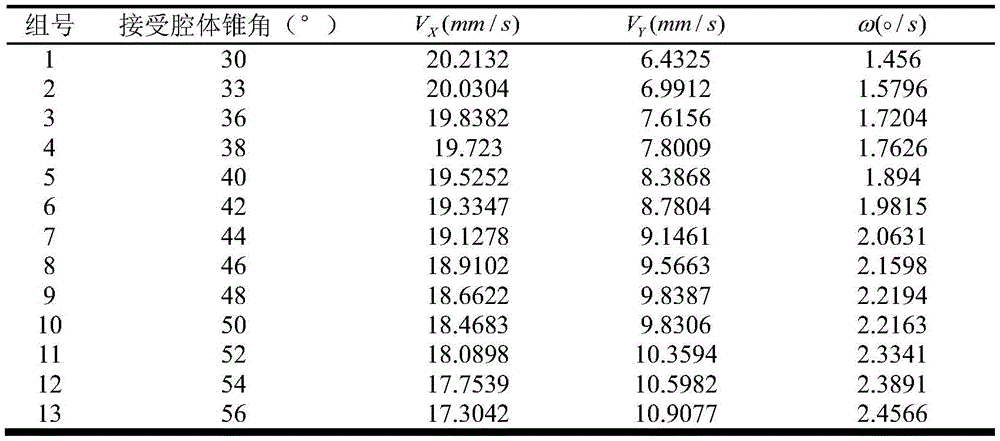

表1数值仿真结果数据表Table 1 Numerical simulation results data table
通过表中的数据可以拟合出速度VX、VY和角速度ω与接受腔体锥角θ之间的变化关系曲线,如图10所示,图中,速度VX随着接受腔体锥角θ的增大而逐渐减小;在接受腔体锥角θ为30°至58°的范围内,速度VY和角速度ω都随着接受腔体锥角θ的增大而逐渐增大;在接受腔体锥角θ为58°至65°的范围内,速度VY和角速度ω都随着接受腔体锥角θ的增大而逐渐减小。以上三条拟合曲线的方程式为:According to the data in the table, we can fit the relationship curve between the velocity V X , V Y and the angular velocity ω and the cone angle θ of the receiving cavity, as shown in Figure 10, in the figure, the velocity V X changes with the cone of the receiving cavity As the angle θ increases, it gradually decreases; in the range of the receiving cavity cone angle θ from 30° to 58°, both the velocity V Y and the angular velocity ω gradually increase with the increase of the receiving cavity cone angle θ; In the range of the receiving cavity cone angle θ from 58° to 65°, both the velocity V Y and the angular velocity ω gradually decrease with the increase of the receiving cavity cone angle θ. The equations of the above three fitting curves are:

得到中心杆球头球心的运动轨迹方程为:The motion trajectory equation of the center of the center club head is obtained as:

经过换算,得到接触碰撞后中心杆球头球心的运动轨迹方程Y=F(X,θ),下面采用数值方法对方程式进行求解。After conversion, the motion trajectory equation Y=F(X, θ) of the center of the ball head of the center rod after the contact collision is obtained, and the equation is solved by numerical method below.
图11为本申请实施例的不同锥角的球头运动轨迹与捕获区域位置关系示意图,如图11所示,为了得到接触点处合适的锥角大小,在同一接触点处选取30°至60°不同的锥角数值代入方程求解可以得出中心杆球头球心在接触后的运动轨迹。图中可以明显的看出,选取锥角大小为30°的运动轨迹偏移在捕获区域的下方,并没有直接进入捕获区域,此时应该调整选取大的锥角,使得中心杆球头球心的运动轨迹往捕获区域偏转;选取锥角大小为60°的运动轨迹也没有直接进入捕获区域,此时应该调整选取小的锥角,使得中心杆球头球心的运动轨迹往捕获区域偏转;选取锥角大小为45°的运动轨迹可以直接进入捕获区域,是此接触点处相对合适的锥角大小。FIG. 11 is a schematic diagram of the relationship between the motion trajectory of the ball head with different taper angles and the position of the capture area according to the embodiment of the application. As shown in FIG. 11 , in order to obtain a suitable taper angle at the contact point, 30° to 60° is selected at the same contact point. °Different cone angle values can be substituted into the equation to solve the movement trajectory of the center of the center of the ball head after contact. It can be clearly seen from the figure that the motion trajectory with a cone angle of 30° is offset below the capture area and does not directly enter the capture area. At this time, a large cone angle should be adjusted to make the center of the ball head of the center rod. The motion trajectory of the center rod is deflected toward the capture area; the motion trajectory with a cone angle of 60° does not directly enter the capture area. At this time, a small cone angle should be adjusted to make the motion trajectory of the center of the ball head of the center rod deflect to the capture area; Selecting a motion trajectory with a cone angle of 45° can directly enter the capture area, which is a relatively suitable cone angle at this contact point.
若取样的间距为Δy=1mm,起始点的纵坐标为ya=20mm,采样接触点的拟合曲线方程为:y=3.7×10-5x3+0.02x2+3.8x-290。经计算分析发现,中心杆球头与接受腔体单次接触碰撞后能直接进入捕获区域,捕获成功。If the sampling interval is Δy=1mm, and the ordinate of the starting point is ya =20mm, the fitting curve equation of the sampling contact point is: y=3.7×10 -5 x 3 +0.02x 2 +3.8x-290. It is found by calculation and analysis that the center club ball head can directly enter the capture area after a single contact collision with the receiving cavity, and the capture is successful.
应理解,说明书通篇中提到的“一个实施例”或“一实施例”意味着与实施例有关的特定特征、结构或特性包括在本发明的至少一个实施例中。因此,在整个说明书各处出现的“在一个实施例中”或“在实施例中”未必一定指相同的实施例。此外,这些特定的特征、结构或特性可以任意适合的方式结合在一个或多个实施例中。应理解,在本发明的各种实施例中,上述各过程的序号的大小并不意味着执行顺序的先后,各过程的执行顺序应以其功能和内在逻辑确定,而不应对本发明实施例的实施过程构成任何限定。上述本发明实施例序号仅仅为了描述,不代表实施例的优劣。It is to be understood that reference throughout the specification to "one embodiment" or "an embodiment" means that a particular feature, structure or characteristic associated with the embodiment is included in at least one embodiment of the present invention. Thus, appearances of "in one embodiment" or "in an embodiment" in various places throughout this specification are not necessarily necessarily referring to the same embodiment. Furthermore, the particular features, structures or characteristics may be combined in any suitable manner in one or more embodiments. It should be understood that, in various embodiments of the present invention, the size of the sequence numbers of the above-mentioned processes does not mean the sequence of execution, and the execution sequence of each process should be determined by its functions and internal logic, rather than the embodiments of the present invention. implementation constitutes any limitation. The above-mentioned serial numbers of the embodiments of the present invention are only for description, and do not represent the advantages or disadvantages of the embodiments.
需要说明的是,在本文中,术语“包括”、“包含”或者其任何其他变体意在涵盖非排他性的包含,从而使得包括一系列要素的过程、方法、物品或者装置不仅包括那些要素,而且还包括没有明确列出的其他要素,或者是还包括为这种过程、方法、物品或者装置所固有的要素。在没有更多限制的情况下,由语句“包括一个……”限定的要素,并不排除在包括该要素的过程、方法、物品或者装置中还存在另外的相同要素。It should be noted that, herein, the terms "comprising", "comprising" or any other variation thereof are intended to encompass non-exclusive inclusion, such that a process, method, article or device comprising a series of elements includes not only those elements, It also includes other elements not expressly listed or inherent to such a process, method, article or apparatus. Without further limitation, an element qualified by the phrase "comprising a..." does not preclude the presence of additional identical elements in a process, method, article or apparatus that includes the element.
在本申请所提供的几个实施例中,应该理解到,所揭露的设备和方法,可以通过其它的方式实现。以上所描述的设备实施例仅是示意性的,例如,所述单元的划分,仅仅为一种逻辑功能划分,实际实现时可以有另外的划分方式,如:多个单元或组件可以结合,或可以集成到另一个系统,或一些特征可以忽略,或不执行。另外,所显示或讨论的各组成部分相互之间的耦合、或直接耦合、或通信连接可以是通过一些接口,设备或单元的间接耦合或通信连接,可以是电性的、机械的或其它形式的。In the several embodiments provided in this application, it should be understood that the disclosed apparatus and method may be implemented in other manners. The device embodiments described above are only illustrative. For example, the division of the units is only a logical function division. In actual implementation, there may be other division methods. For example, multiple units or components may be combined, or Can be integrated into another system, or some features can be ignored, or not implemented. In addition, the coupling, or direct coupling, or communication connection between the components shown or discussed may be through some interfaces, and the indirect coupling or communication connection of devices or units may be electrical, mechanical or other forms. of.
上述作为分离部件说明的单元可以是、或也可以不是物理上分开的,作为单元显示的部件可以是、或也可以不是物理单元;既可以位于一个地方,也可以分布到多个网络单元上;可以根据实际的需要选择其中的部分或全部单元来实现本实施例方案的目的。The unit described above as a separate component may or may not be physically separated, and the component displayed as a unit may or may not be a physical unit; it may be located in one place or distributed to multiple network units; Some or all of the units may be selected according to actual needs to achieve the purpose of the solution in this embodiment.
另外,在本发明各实施例中的各功能单元可以全部集成在一个处理单元中,也可以是各单元分别单独作为一个单元,也可以两个或两个以上单元集成在一个单元中;上述集成的单元既可以采用硬件的形式实现,也可以采用硬件加软件功能单元的形式实现。In addition, each functional unit in each embodiment of the present invention may all be integrated into one processing unit, or each unit may be separately used as a unit, or two or more units may be integrated into one unit; the above-mentioned integration The unit can be implemented either in the form of hardware or in the form of hardware plus software functional units.
以上所述,仅为本发明的实施方式,但本发明的保护范围并不局限于此,任何熟悉本技术领域的技术人员在本发明揭露的技术范围内,可轻易想到变化或替换,都应涵盖在本发明的保护范围之内。因此,本发明的保护范围应以所述权利要求的保护范围为准。The above are only the embodiments of the present invention, but the protection scope of the present invention is not limited to this. Any person skilled in the art who is familiar with the technical scope disclosed by the present invention can easily think of changes or substitutions. Included within the scope of protection of the present invention. Therefore, the protection scope of the present invention should be based on the protection scope of the claims.
Claims (5)


Priority Applications (1)
| Application Number | Priority Date | Filing Date | Title |
|---|---|---|---|
| CN202010957674.6A CN112046797B (en) | 2020-09-11 | 2020-09-11 | capture docking device |
Applications Claiming Priority (1)
| Application Number | Priority Date | Filing Date | Title |
|---|---|---|---|
| CN202010957674.6A CN112046797B (en) | 2020-09-11 | 2020-09-11 | capture docking device |
Publications (2)
| Publication Number | Publication Date |
|---|---|
| CN112046797A CN112046797A (en) | 2020-12-08 |
| CN112046797B true CN112046797B (en) | 2022-06-24 |
Family
ID=73611654
Family Applications (1)
| Application Number | Title | Priority Date | Filing Date |
|---|---|---|---|
| CN202010957674.6A Active CN112046797B (en) | 2020-09-11 | 2020-09-11 | capture docking device |
Country Status (1)
| Country | Link |
|---|---|
| CN (1) | CN112046797B (en) |
Families Citing this family (1)
| Publication number | Priority date | Publication date | Assignee | Title |
|---|---|---|---|---|
| CN114435634B (en) * | 2021-12-29 | 2023-05-23 | 中国人民解放军国防科技大学 | Combination and separation motorized flying net and space target capturing method |
Citations (1)
| Publication number | Priority date | Publication date | Assignee | Title |
|---|---|---|---|---|
| CN1212940A (en) * | 1997-09-26 | 1999-04-07 | 建筑航空股份有限公司 | A system for securing and detaching artificial satellites |
Family Cites Families (6)
| Publication number | Priority date | Publication date | Assignee | Title |
|---|---|---|---|---|
| JPH01226498A (en) * | 1988-03-07 | 1989-09-11 | Nec Corp | Undocking/docking device of spacecraft |
| US6816185B2 (en) * | 2000-12-29 | 2004-11-09 | Miki Harmath | System and method for judging boundary lines |
| CN104494846B (en) * | 2014-12-16 | 2016-05-04 | 中国空间技术研究院 | A kind of general arresting agency of weak shock that is applicable to high rail satellite |
| CN107215485B (en) * | 2017-05-31 | 2019-07-12 | 北京空间飞行器总体设计部 | A passive trigger locking device |
| CN207536139U (en) * | 2017-07-12 | 2018-06-26 | 江南大学 | A kind of cone rod-type docking mechanism |
| CN108622440A (en) * | 2018-07-16 | 2018-10-09 | 哈尔滨理工大学 | A kind of three-pawl type Space Docking Mechanism |
-
2020
- 2020-09-11 CN CN202010957674.6A patent/CN112046797B/en active Active
Patent Citations (1)
| Publication number | Priority date | Publication date | Assignee | Title |
|---|---|---|---|---|
| CN1212940A (en) * | 1997-09-26 | 1999-04-07 | 建筑航空股份有限公司 | A system for securing and detaching artificial satellites |
Also Published As
| Publication number | Publication date |
|---|---|
| CN112046797A (en) | 2020-12-08 |
Similar Documents
| Publication | Publication Date | Title |
|---|---|---|
| CN102490181B (en) | Gripping mechanism for replacing spatial on-orbit modules | |
| US8333347B2 (en) | Docking system | |
| CN104176279B (en) | A kind of noncooperative target capture mechanism | |
| CN113608346B (en) | Super-large space telescope modularized sub-mirror splicing scheme and standardized interface | |
| CN109050992B (en) | Docking type multi-module cooperative flexible taper rod type docking mechanism and working method thereof | |
| CN112357129B (en) | Radome fairing inclined pushing axial separation device | |
| CN110217410B (en) | Docking ring capturing and locking mechanism and capturing and locking method | |
| CN109080858A (en) | A kind of low impact redundancy unlock connection tripper | |
| CN112046797B (en) | capture docking device | |
| CN109573114B (en) | Cone-rod telescopic and tightening mechanism based on bidirectional helical groove drive | |
| US12371195B2 (en) | Vehicle capture assemblies and related devices, systems, and methods | |
| US10766639B2 (en) | Actuated resettable shockless hold down and release mechanism (AReS HDRM) | |
| US12448152B2 (en) | In-space grasping system and method of operation | |
| Aikenhead et al. | Canadarm and the space shuttle | |
| JP2025063047A (en) | Method and system for multi-object space debris removal - Patents.com | |
| US20240083602A1 (en) | Vehicle capture assemblies and related devices, systems, and methods | |
| US20240392906A1 (en) | A Device As Quick Coupling Interface For Dual Docking And Refuelling | |
| CN109606751B (en) | A universal taper-rod capture mechanism for high-orbit satellites | |
| Wang et al. | A brief review of the space docking mechanism | |
| CN119217418B (en) | Multifunctional tail end integrating capturing, locking, driving output and power supply | |
| US20250192429A1 (en) | Systems and methods for holding and releasing a large antenna reflector | |
| CN108482715A (en) | Space locking and unlocking device with unlocking and unfolding functions | |
| CN113353235A (en) | Mechanism capable of realizing locking and separation between combined aircrafts and working method | |
| CN116252972B (en) | An electromagnetic docking device for on-orbit assembly of micro-nano satellites | |
| AU2023347642A1 (en) | Mechanism for attachment and detachment of an airfoil to an airframe |
Legal Events
| Date | Code | Title | Description |
|---|---|---|---|
| PB01 | Publication | ||
| PB01 | Publication | ||
| SE01 | Entry into force of request for substantive examination | ||
| SE01 | Entry into force of request for substantive examination | ||
| GR01 | Patent grant | ||
| GR01 | Patent grant |