CN112003384B - Electron Periodic Reciprocating Flow Method for Electric Field Coupled Wireless Power Transmission System - Google Patents
Electron Periodic Reciprocating Flow Method for Electric Field Coupled Wireless Power Transmission System Download PDFInfo
- Publication number
- CN112003384B CN112003384B CN202010738628.7A CN202010738628A CN112003384B CN 112003384 B CN112003384 B CN 112003384B CN 202010738628 A CN202010738628 A CN 202010738628A CN 112003384 B CN112003384 B CN 112003384B
- Authority
- CN
- China
- Prior art keywords
- coupling
- current
- wireless power
- electric field
- power transmission
- Prior art date
- Legal status (The legal status is an assumption and is not a legal conclusion. Google has not performed a legal analysis and makes no representation as to the accuracy of the status listed.)
- Active
Links
- 230000005684 electric field Effects 0.000 title claims abstract description 74
- 230000005540 biological transmission Effects 0.000 title claims abstract description 65
- 230000000737 periodic effect Effects 0.000 title claims abstract description 21
- 238000000034 method Methods 0.000 title claims abstract description 15
- 238000010168 coupling process Methods 0.000 claims abstract description 168
- 238000005859 coupling reaction Methods 0.000 claims abstract description 168
- 230000008878 coupling Effects 0.000 claims abstract description 143
- 239000003990 capacitor Substances 0.000 claims abstract description 55
- 238000002955 isolation Methods 0.000 claims abstract description 12
- 239000013535 sea water Substances 0.000 claims description 40
- 150000003839 salts Chemical class 0.000 claims description 3
- 230000003068 static effect Effects 0.000 claims description 3
- 239000004020 conductor Substances 0.000 claims 1
- 238000010586 diagram Methods 0.000 description 10
- 239000002184 metal Substances 0.000 description 5
- 229910052751 metal Inorganic materials 0.000 description 5
- 238000005516 engineering process Methods 0.000 description 4
- 150000002739 metals Chemical class 0.000 description 3
- 230000009286 beneficial effect Effects 0.000 description 1
- 230000000694 effects Effects 0.000 description 1
- 239000003350 kerosene Substances 0.000 description 1
- 239000007769 metal material Substances 0.000 description 1
- 230000003287 optical effect Effects 0.000 description 1
- XLYOFNOQVPJJNP-UHFFFAOYSA-N water Substances O XLYOFNOQVPJJNP-UHFFFAOYSA-N 0.000 description 1
Images


Classifications
-
- H—ELECTRICITY
- H02—GENERATION; CONVERSION OR DISTRIBUTION OF ELECTRIC POWER
- H02J—CIRCUIT ARRANGEMENTS OR SYSTEMS FOR SUPPLYING OR DISTRIBUTING ELECTRIC POWER; SYSTEMS FOR STORING ELECTRIC ENERGY
- H02J50/00—Circuit arrangements or systems for wireless supply or distribution of electric power
- H02J50/05—Circuit arrangements or systems for wireless supply or distribution of electric power using capacitive coupling
-
- Y—GENERAL TAGGING OF NEW TECHNOLOGICAL DEVELOPMENTS; GENERAL TAGGING OF CROSS-SECTIONAL TECHNOLOGIES SPANNING OVER SEVERAL SECTIONS OF THE IPC; TECHNICAL SUBJECTS COVERED BY FORMER USPC CROSS-REFERENCE ART COLLECTIONS [XRACs] AND DIGESTS
- Y02—TECHNOLOGIES OR APPLICATIONS FOR MITIGATION OR ADAPTATION AGAINST CLIMATE CHANGE
- Y02T—CLIMATE CHANGE MITIGATION TECHNOLOGIES RELATED TO TRANSPORTATION
- Y02T90/00—Enabling technologies or technologies with a potential or indirect contribution to GHG emissions mitigation
- Y02T90/10—Technologies relating to charging of electric vehicles
- Y02T90/14—Plug-in electric vehicles
Landscapes
- Engineering & Computer Science (AREA)
- Computer Networks & Wireless Communication (AREA)
- Power Engineering (AREA)
- Current-Collector Devices For Electrically Propelled Vehicles (AREA)
Abstract
Description
技术领域technical field
本发明属于无线电能传输技术领域,具体涉及一种电场耦合式无线电能传输系统的电子周期性往复流动方法。The invention belongs to the technical field of wireless power transmission, and in particular relates to an electronic periodic reciprocating flow method of an electric field coupled wireless power transmission system.
背景技术Background technique
无线电能传输是一种无需物理接触即可实现电能传输的技术。目前已经有多种无线电能传输的方法包括基于磁场耦合的无线电能传输、基于电场耦合的无线电能传输、基于激光的光功率传输和远场RF微波能量传输。磁场耦合式无线电能传输系统利用频率范围为kHz—MHz的非辐射磁场来实现无线电能传输的功能,耦合电感被用来产生磁场。磁场耦合式无线电能传输系统已广泛应用于水下设备、植入式医疗设备、移动设备、电动汽车和无人驾驶飞机。在空气介质中应用时,磁场耦合式无线电能传输技术具有高效率、电流隔离和高可靠性的优势。Wireless power transfer is a technology that enables power transfer without physical contact. There are many methods of wireless power transfer, including magnetic field coupling-based wireless power transfer, electric field coupling-based wireless power transfer, laser-based optical power transfer, and far-field RF microwave power transfer. The magnetic field coupling wireless power transfer system uses the non-radiative magnetic field in the frequency range of kHz-MHz to realize the function of wireless power transfer, and the coupled inductor is used to generate the magnetic field. Magnetic field coupled wireless power transfer systems have been widely used in underwater devices, implantable medical devices, mobile devices, electric vehicles and drones. When applied in the air medium, the magnetic field coupled wireless power transfer technology has the advantages of high efficiency, galvanic isolation and high reliability.
在海水环境中,水下磁场耦合式无线电能传输系统在导电的海水中将会产生涡流损耗,电感线圈之间的互感会随着海水电导率的变化而变化,而海水电导率会随着海水温度和盐度的变化而变化。水下磁场耦合式无线电能传输系统会同时会受到海水压强的影响而产生“压磁效应”,除此之外,水下磁场耦合式无线电能传输系统还对附近金属材料非常敏感,它会产生多余的热量并伴随着大量的能量损失。In the seawater environment, the underwater magnetic field coupled wireless power transmission system will generate eddy current loss in the conductive seawater, and the mutual inductance between the inductor coils will change with the seawater conductivity, and the seawater conductivity will change with the seawater. changes in temperature and salinity. The underwater magnetic field coupled wireless power transmission system will be affected by the seawater pressure at the same time to produce a "piezomagnetic effect". In addition, the underwater magnetic field coupled wireless power transmission system is also very sensitive to nearby metal materials, which will produce The excess heat is accompanied by a large amount of energy loss.
与磁场耦合式无线电能传输系统相比,电场耦合式无线电能传输系统采用非常高频率的(MHz)的电场,将电能从发送端传输到接收端。发射端的耦合极板和接收端耦合极板共同组成耦合电容机构。一般情况下,电场耦合式无线电能传输系统常用于低功率场合。近年来,电场耦合式无线电能传输系统开始应用于数千瓦功率等级、数十厘米传输距离的无线电能传输。电场耦合式无线电能传输系统技术得到了高度发展,这项技术也可以用于电动汽车和全电动飞机。Compared with the magnetic field coupled wireless power transfer system, the electric field coupled wireless power transfer system uses a very high frequency (MHz) electric field to transfer power from the transmitter to the receiver. The coupling plate at the transmitting end and the coupling plate at the receiving end together form a coupling capacitor mechanism. In general, electric field-coupled wireless power transfer systems are often used in low-power applications. In recent years, electric field-coupled wireless power transmission systems have begun to be applied to wireless power transmission with a power level of several kilowatts and a transmission distance of tens of centimeters. Electric field-coupled wireless power transfer system technology is highly developed, and this technology can also be used in electric vehicles and all-electric aircraft.
由于海水的介电常数大概是自由空间或者空气的81倍,因此,在海水介质中,电场耦合式无线电能传输系统的海下电能传输能力将大大增强。在导电海水中,电场耦合式无线电能传输系统具有系统结构简单、无涡流损耗等优点,且在运行时受周围金属的影响不大。另外,只采用金属板作为无线电能传输的媒介,其可以很大程度上降低成本。因此,电场耦合式无线电能传输系统将会在海下无线电能传输方面具有光明的应用前景。然而,电场耦合式无线电能传输系统只能工作在闭环电路中,且电子只能在一个完整的电路闭环中流动。目前还没有文章或者报告中提出如何利用基于双耦合极板的电场耦合式无线电能传输系统实现海下无线电能传输的应用。电子的周期性往复流动方法将会给电场耦合式无线电能传输系统在海下的应用提供一种新的思路。Since the dielectric constant of seawater is about 81 times that of free space or air, in seawater medium, the ability of electric field coupled wireless power transfer system to transmit power under sea will be greatly enhanced. In conductive seawater, the electric field-coupled wireless power transmission system has the advantages of simple system structure, no eddy current loss, etc., and is not affected by surrounding metals during operation. In addition, only the metal plate is used as the medium for wireless power transmission, which can greatly reduce the cost. Therefore, the electric field coupled wireless power transmission system will have a bright application prospect in the wireless power transmission under the sea. However, the electric field-coupled wireless power transfer system can only work in a closed-loop circuit, and electrons can only flow in a complete closed-loop circuit. There is no article or report that proposes how to use the electric field coupled wireless power transfer system based on double-coupling plates to realize the application of underwater wireless power transfer. The periodic reciprocating flow method of electrons will provide a new idea for the application of electric field-coupled wireless power transfer systems under the sea.
在这种背景下,本发明专利提出一种电场耦合式水下无线电能传输系统的电子周期性往复流动理论。In this context, the patent of the present invention proposes a periodic reciprocating flow theory of electrons in an electric field coupled underwater wireless power transmission system.
发明内容SUMMARY OF THE INVENTION
本发明的目的是提供一种电场耦合式无线电能传输系统的电子周期性往复流动方法,解决了现有技术中存在的电场耦合式无线电能传输系统只能工作在闭环电路中,且电子只能在一个完整的电路闭环中流动的问题。The purpose of the present invention is to provide a periodic reciprocating flow method of electrons in an electric field coupling wireless power transmission system, which solves the problem that the electric field coupling wireless power transmission system existing in the prior art can only work in a closed-loop circuit, and the electrons can only The problem of flow in a complete circuit closed loop.
本发明所采用的技术方案是,电场耦合式无线电能传输系统的电子周期性往复流动方法,具体按照以下步骤实施:The technical scheme adopted by the present invention is that the electronic periodic reciprocating flow method of the electric field coupled wireless power transmission system is specifically implemented according to the following steps:
步骤1、建立双耦合极板电场耦合式无线电能传输系统拓扑结构;Step 1. Establish a topology structure of a double-coupling plate electric field-coupled wireless power transmission system;
步骤2、假设电流方向在半个开关周期内只改变一次,上半个开关周期内,原边电流I1F从电源Vin流向电感L1和耦合极板P1;同时,在系统的副边,电流I2F从耦合极板P2和电感L2流向输出滤波电容Co和负载,在上半个开关周期内,完成电流从系统原边向系统副边的正向流动,耦合电容为隔离单元;Step 2. Assuming that the current direction changes only once in the half switching cycle, in the first half switching cycle, the primary current I 1F flows from the power supply V in to the inductor L 1 and the coupling plate P 1 ; at the same time, on the secondary side of the system , the current I 2F flows from the coupling plate P 2 and the inductor L 2 to the output filter capacitor C o and the load. In the first half of the switching cycle, the current flows from the primary side of the system to the secondary side of the system. The coupling capacitor is an isolation unit;
步骤3、在下半个开关周期内,系统原边电流I1S从耦合极板P1和电感L1流向地G1,同时,在系统的副边,电流I2S从电感L2流向耦合极板P2,在下半个开关周期内,完成电流从系统副边向系统原边的反向流动,耦合电容为隔离单元;Step 3. In the second half of the switching cycle, the primary current I 1S of the system flows from the coupling plate P 1 and the inductor L 1 to the ground G 1 , and at the secondary side of the system, the current I 2S flows from the inductor L 2 to the coupling plate P 2 , in the second half of the switching cycle, the reverse flow of current from the secondary side of the system to the primary side of the system is completed, and the coupling capacitor is the isolation unit;
步骤4、在导电介质中,双耦合极板电场耦合式无线电能传输系统,耦合电容作为隔离单元,在一个周期内组成一个闭环电路,同时,在一个周期内完成电能从系统原边向系统副边的传递,从而,形成电子的周期性往复流动。Step 4. In the conductive medium, the double-coupling plate electric field-coupled wireless power transmission system uses the coupling capacitor as an isolation unit to form a closed-loop circuit in one cycle. The transfer of edges, thus, forms a periodic back-and-forth flow of electrons.
本发明的特点还在于,The present invention is also characterized in that,
步骤1中双耦合极板电场耦合式无线电能传输系统拓扑结构具体为:包括耦合极板P1和耦合极板P2,耦合极板P1和耦合极板P2之间填充有导电介质,耦合极板P1与电感L1串联后连接至系统输入侧,系统输入侧包括开关管S1和开关管S2通过自身串联的形式与电源Vin并联连接,开关耦合极板P2与电感L2串联后连接至系统输出侧,系统输出侧包括二极管D1和二极管D2通过自身串联的形式与输出滤波电容Co和负载并联连接。In step 1, the topological structure of the double-coupling-pole electric field-coupled wireless power transmission system is specifically: including the coupling pole plate P 1 and the coupling pole plate P 2 , and a conductive medium is filled between the coupling pole plate P 1 and the coupling pole plate P 2 , The coupling plate P 1 is connected to the input side of the system after being connected in series with the inductor L 1. The input side of the system includes the switch tube S 1 and the switch tube S 2 connected in parallel with the power supply V in in the form of their own series connection, and the switch coupling plate P 2 is connected to the inductor. L 2 is connected in series to the output side of the system, and the output side of the system includes diode D 1 and diode D 2 connected in parallel with the output filter capacitor C o and the load in the form of their own series connection.
耦合极板P1和耦合极板P2之间填充的导电介质为海水。The conductive medium filled between the coupling plate P 1 and the coupling plate P 2 is seawater.
步骤2具体如下:Step 2 is as follows:
在海水条件下,海水导电介质的介电常数、温度、盐浓度和电磁波的角频率有如下关系:Under seawater conditions, the dielectric constant, temperature, salt concentration and angular frequency of electromagnetic waves of seawater conductive medium are related as follows:

其中,εsea(S,T,ω)为海水导电介质的介电常数,ε∞(S,T)是频率无限大时的海水介电常数,ε0是自由空间的介电常数,ε0=8.854×10⁻¹²Fm-1,ω=2πf,f是电磁波的频率,εS(S,T)是海水的静态介电常数,δ(S,T)是海水的离子电导率,τ(S,T)是德拜驰豫时间;S为海水盐度,T为海水温度;Among them, ε sea (S, T, ω) is the dielectric constant of seawater conducting medium, ε ∞ (S, T) is the seawater dielectric constant when the frequency is infinite, ε 0 is the dielectric constant of free space, ε 0 =8.854×10 -12 Fm -1 , ω=2πf, f is the frequency of electromagnetic waves, ε S (S, T) is the static permittivity of seawater, δ(S, T) is the ionic conductivity of seawater, τ( S, T) is the Debye relaxation time; S is the seawater salinity, T is the seawater temperature;
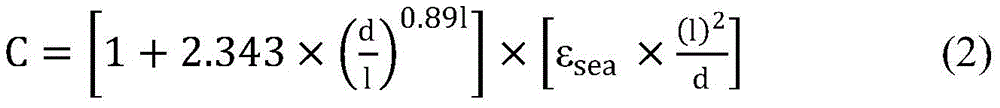
在海水介质中,两个耦合极板所组成的电容C表示为:In seawater medium, the capacitance C composed of two coupled plates is expressed as:

其中,l表示耦合极板的长度,d表示为发射端耦合极板和接收端耦合极板之间的距离;Among them, l represents the length of the coupling plate, and d represents the distance between the transmitting-end coupling plate and the receiving-end coupling plate;
在双耦合极板电场耦合式无线电能传输系统中,耦合电容CM表示为:In the double-coupling plate electric field-coupled wireless power transmission system, the coupling capacitance C M is expressed as:
CM=C (3)C M = C (3)
通过半桥逆变电路,原边的谐振电压vP为:Through the half-bridge inverter circuit, the resonant voltage v P of the primary side is:

通过半桥整流电路,副边的谐振电压vS和负载电压v0有如下关系:Through the half-bridge rectifier circuit, the resonant voltage v S of the secondary side and the load voltage v 0 have the following relationship:

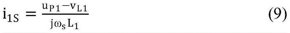
在上半个开关周期内,基于基尔霍夫电流定律KCL和基尔霍夫电压定律KVL原则,原边电流i1F和副边电流i2F表示为:In the first half of the switching cycle, based on Kirchhoff's current law KCL and Kirchhoff's voltage law KVL principles, the primary current i 1F and the secondary current i 2F are expressed as:


其中,vin为输入电压,vL1为电感L1电压,uP1为耦合极板P1的电压,L1为电感L1的电感值,uP2为耦合极板P2的电压,vL2为电感L2的电压,v0为电场耦合式无线电能传输系统的输出电压,RL为负载电阻值,L2为电感L2的电感值,C0为输出滤波电容Co的电容值,ωS=2πfS,fS是开关频率;Among them, v in is the input voltage, v L1 is the voltage of the inductor L 1 , u P1 is the voltage of the coupling plate P 1 , L 1 is the inductance value of the inductor L 1 , u P2 is the voltage of the coupling plate P 2 , v L2 is the voltage of the inductor L 2 , v 0 is the output voltage of the electric field-coupled wireless power transmission system, R L is the load resistance value, L 2 is the inductance value of the inductor L 2 , C 0 is the output filter capacitor C o The capacitance value, ω S = 2πf S , f S is the switching frequency;
在上半个开关周期内,耦合电容的电流iCF表示为:During the first half switching cycle, the current i CF of the coupling capacitor is expressed as:

其中,C为耦合电容的等效电容值。Among them, C is the equivalent capacitance value of the coupling capacitor.
步骤3具体如下:Step 3 is as follows:
下半个开关周期内,基于基尔霍夫电流定律KCL和基尔霍夫电压定律KVL原则,原边电流i1S和副边电流i2S表示为:In the second half of the switching cycle, based on Kirchhoff's current law KCL and Kirchhoff's voltage law KVL, the primary side current i 1S and the secondary side current i 2S are expressed as:


在下半个开关周期内,耦合电容的电流iCS表示为:During the second half of the switching cycle, the current i CS of the coupling capacitor is expressed as:

步骤4具体如下:Step 4 is as follows:
在一个开关周期内,耦合电容的充放电量保持平衡,表示为:In one switching cycle, the charge and discharge of the coupling capacitors are kept in balance, which is expressed as:

其中,ICF为上半个开关周期内耦合电容的充电电流,ICS为下半个开关周期内耦合电容的放电电流;Among them, I CF is the charging current of the coupling capacitor in the first half of the switching period, and I CS is the discharge current of the coupling capacitor in the second half of the switching period;
在一个开关周期,耦合电容等效为完成了一次充电和放电,电流在系统中往复流动两次,从而完成电能从电场耦合式无线电能传输系统的原边向副边的传递。In one switching cycle, the coupling capacitor is equivalent to completing one charge and discharge, and the current flows back and forth in the system twice, thus completing the transfer of electrical energy from the primary side to the secondary side of the electric field coupled wireless power transfer system.
本发明的有益效果是,(1)本发明的电场耦合式水下无线电能传输系统无涡流损耗且对周围金属的存在不敏感,其非常适合水下无线充电场景,且可以大功率、高效率运行;(2)在动态的水下环境中,可以为水下设备进行稳定的隔离式充电。通过使用基于海水介质的双耦合极板电场耦合式无线电能传输系统,结合本发明中所提出的新的电场耦合式无线电能传输系统的电子周期性往复流动理论实现稳定和便捷的海下无线电能传输;(3)电场耦合式水下无线电能传输系统仅仅采用金属板就可以实现对水下设备的充电,其可以很大程度上降低水下无线电能传输的成本;(4)本发明的所提出的新的电场耦合式无线电能传输系统的电子周期性往复流动理论,可以为电场耦合式无线电能传输系统在海下的应用提供一种新的解决方案。The beneficial effects of the present invention are that (1) the electric field coupled underwater wireless power transmission system of the present invention has no eddy current loss and is insensitive to the existence of surrounding metals, it is very suitable for underwater wireless charging scenarios, and can achieve high power and high efficiency (2) In a dynamic underwater environment, stable and isolated charging can be performed for underwater equipment. By using the double-coupling-pole electric field-coupled wireless power transfer system based on the seawater medium, combined with the periodic reciprocating flow theory of electrons in the new electric field-coupled wireless power transfer system proposed in the present invention, stable and convenient underwater wireless power is realized (3) The electric field-coupled underwater wireless power transmission system can only use metal plates to charge the underwater equipment, which can greatly reduce the cost of underwater wireless power transmission; The proposed new theory of the periodic reciprocating flow of electrons in the electric field coupled wireless power transfer system can provide a new solution for the application of the electric field coupled wireless power transfer system under the sea.
附图说明Description of drawings
图1是本发明所涉及的一种双耦合极板电场耦合式无线电能传输系统拓扑;Fig. 1 is a kind of double-coupling polar plate electric field coupling type wireless power transmission system topology related to the present invention;
图2(a)本发明所涉及的双耦合极板电场耦合式无线电能传输系统上半个开关周期电子流动示意图;Figure 2 (a) schematic diagram of electron flow in the first half switching cycle of the double-coupling plate electric field-coupled wireless power transmission system involved in the present invention;
图2(b)是本发明所涉及的双耦合极板电场耦合式无线电能传输系统上半个开关周期等效电路图;Fig. 2 (b) is the equivalent circuit diagram of the first half switching cycle of the double-coupling plate electric field coupling wireless power transmission system involved in the present invention;
图3(a)是本发明所涉及的双耦合极板电场耦合式无线电能传输系统下半个开关周期电子流动示意图;Figure 3 (a) is a schematic diagram of the electron flow in the second half of the switching cycle of the double-coupling plate electric field-coupled wireless power transmission system involved in the present invention;
图3(b)是本发明所涉及的双耦合极板电场耦合式无线电能传输系统下半个开关周期等效电路图;Fig. 3 (b) is the equivalent circuit diagram of the second half switching cycle of the double-coupling plate electric field coupling wireless power transmission system involved in the present invention;
图4(a)是在导电介质中,当耦合极板P1的电压大于耦合极板P2的电压时,双耦合极板电场耦合式无线电能传输系统电子流动示意图;Figure 4 (a) is a schematic diagram of electron flow in a double-coupling-pole electric field-coupled wireless power transmission system in a conductive medium, when the voltage of the coupling plate P1 is greater than the voltage of the coupling plate P2 ;
图4(b)是在导电介质中,当耦合极板P1的电压小于耦合极板P2的电压时,双耦合极板电场耦合式无线电能传输系统电子流动示意图。Figure 4(b) is a schematic diagram of electron flow in a double-coupling-plate electric field - coupled wireless power transfer system when the voltage of the coupling plate P1 is less than the voltage of the coupling plate P2 in a conductive medium.
具体实施方式Detailed ways
下面结合附图和具体实施方式对本发明进行详细说明。The present invention will be described in detail below with reference to the accompanying drawings and specific embodiments.
本发明电场耦合式无线电能传输系统的电子周期性往复流动方法,具体按照以下步骤实施:The periodic reciprocating flow method of electrons in the electric field coupling wireless power transmission system of the present invention is specifically implemented according to the following steps:
步骤1、建立双耦合极板电场耦合式无线电能传输系统拓扑结构;Step 1. Establish a topology structure of a double-coupling plate electric field-coupled wireless power transmission system;
如图1所示,步骤1中双耦合极板电场耦合式无线电能传输系统拓扑结构具体为:包括耦合极板P1和耦合极板P2,耦合极板P1和耦合极板P2之间填充有导电介质,耦合极板P1与电感L1串联后连接至系统输入侧,系统输入侧包括开关管S1和开关管S2通过自身串联的形式与电源Vin并联连接,开关耦合极板P2与电感L2串联后连接至系统输出侧,系统输出侧包括二极管D1和二极管D2通过自身串联的形式与输出滤波电容Co和负载并联连接。As shown in FIG. 1 , the topological structure of the double-coupling plate electric field coupling wireless power transmission system in step 1 is specifically: including the coupling plate P 1 and the coupling plate P 2 , and the coupling plate P 1 and the coupling plate P 2 The space is filled with a conductive medium, and the coupling plate P 1 is connected to the input side of the system after being connected in series with the inductor L 1. The input side of the system includes the switch tube S 1 and the switch tube S 2 connected in parallel with the power supply V in in the form of their own series connection, and the switch is coupled to The pole plate P 2 is connected in series with the inductor L 2 to the system output side. The system output side includes diodes D 1 and D 2 connected in parallel with the output filter capacitor C o and the load in the form of their own series connection.
耦合极板P1和耦合极板P2之间填充的导电介质为海水。The conductive medium filled between the coupling plate P 1 and the coupling plate P 2 is seawater.
步骤2、假设电流方向在半个开关周期内只改变一次,上半个开关周期内,原边电流I1F从电源Vin流向电感L1和耦合极板P1;同时,在系统的副边,电流I2F从耦合极板P2和电感L2流向输出滤波电容Co和负载,在上半个开关周期内,完成电流从系统原边向系统副边的正向流动,耦合电容为隔离单元;Step 2. Assuming that the current direction changes only once in the half switching cycle, in the first half switching cycle, the primary current I 1F flows from the power supply V in to the inductor L 1 and the coupling plate P 1 ; at the same time, on the secondary side of the system , the current I 2F flows from the coupling plate P 2 and the inductor L 2 to the output filter capacitor C o and the load. In the first half of the switching cycle, the current flows from the primary side of the system to the secondary side of the system. The coupling capacitor is an isolation unit;
步骤2具体如下:Step 2 is as follows:
在海水条件下,海水导电介质的介电常数、温度、盐浓度和电磁波的角频率有如下关系:Under seawater conditions, the dielectric constant, temperature, salt concentration and angular frequency of electromagnetic waves of seawater conductive medium are related as follows:

其中,εsea(S,T,ω)为海水导电介质的介电常数,ε∞(S,T)是频率无限大时的海水介电常数,ε0是自由空间的介电常数,ε0=8.854×10⁻¹²Fm-1,ω=2πf,f是电磁波的频率,εS(S,T)是海水的静态介电常数,δ(S,T)是海水的离子电导率,τ(S,T)是德拜驰豫时间;S为海水盐度,T为海水温度;Among them, ε sea (S, T, ω) is the dielectric constant of seawater conducting medium, ε ∞ (S, T) is the seawater dielectric constant when the frequency is infinite, ε 0 is the dielectric constant of free space, ε 0 =8.854×10 -12 Fm -1 , ω=2πf, f is the frequency of electromagnetic waves, ε S (S, T) is the static permittivity of seawater, δ(S, T) is the ionic conductivity of seawater, τ( S, T) is the Debye relaxation time; S is the seawater salinity, T is the seawater temperature;
在海水介质中,两个耦合极板所组成的电容C表示为:In seawater medium, the capacitance C composed of two coupled plates is expressed as:

其中,l表示耦合极板的长度,d表示为发射端耦合极板和接收端耦合极板之间的距离;Among them, l represents the length of the coupling plate, and d represents the distance between the transmitting-end coupling plate and the receiving-end coupling plate;
在双耦合极板电场耦合式无线电能传输系统中,耦合电容CM表示为:In the double-coupling plate electric field-coupled wireless power transmission system, the coupling capacitance C M is expressed as:
CM=C (3)C M = C (3)
通过半桥逆变电路,原边的谐振电压vP为:Through the half-bridge inverter circuit, the resonant voltage v P of the primary side is:

通过半桥整流电路,副边的谐振电压vS和负载电压v0有如下关系:Through the half-bridge rectifier circuit, the resonant voltage v S of the secondary side and the load voltage v 0 have the following relationship:

在上半个开关周期内,基于基尔霍夫电流定律KCL和基尔霍夫电压定律KVL原则,原边电流i1F和副边电流i2F表示为:In the first half of the switching cycle, based on Kirchhoff's current law KCL and Kirchhoff's voltage law KVL principles, the primary current i 1F and the secondary current i 2F are expressed as:


其中,vin为输入电压,vL1为电感L1电压,uP1为耦合极板P1的电压,L1为电感L1的电感值,uP2为耦合极板P2的电压,vL2为电感L2的电压,v0为电场耦合式无线电能传输系统的输出电压,RL为负载电阻值,L2为电感L2的电感值,C0为输出滤波电容Co的电容值,ωS=2πfS,fS是开关频率;Among them, v in is the input voltage, v L1 is the voltage of the inductor L 1 , u P1 is the voltage of the coupling plate P 1 , L 1 is the inductance value of the inductor L 1 , u P2 is the voltage of the coupling plate P 2 , v L2 is the voltage of the inductor L 2 , v 0 is the output voltage of the electric field-coupled wireless power transmission system, R L is the load resistance value, L 2 is the inductance value of the inductor L 2 , C 0 is the output filter capacitor C o The capacitance value, ω S = 2πf S , f S is the switching frequency;
在上半个开关周期内,耦合电容的电流iCF表示为:During the first half switching cycle, the current i CF of the coupling capacitor is expressed as:

其中,C为耦合电容的等效电容值。Among them, C is the equivalent capacitance value of the coupling capacitor.
步骤3、在下半个开关周期内,系统原边电流I1S从耦合极板P1和电感L1流向地G1,同时,在系统的副边,电流I2S从电感L2流向耦合极板P2,在下半个开关周期内,完成电流从系统副边向系统原边的反向流动,耦合电容为隔离单元;Step 3. In the second half of the switching cycle, the primary current I 1S of the system flows from the coupling plate P 1 and the inductor L 1 to the ground G 1 , and at the secondary side of the system, the current I 2S flows from the inductor L 2 to the coupling plate P 2 , in the second half of the switching cycle, the reverse flow of current from the secondary side of the system to the primary side of the system is completed, and the coupling capacitor is the isolation unit;
步骤3具体如下:Step 3 is as follows:
下半个开关周期内,基于基尔霍夫电流定律KCL和基尔霍夫电压定律KVL原则,原边电流i1S和副边电流i2S表示为:In the second half of the switching cycle, based on Kirchhoff's current law KCL and Kirchhoff's voltage law KVL, the primary side current i 1S and the secondary side current i 2S are expressed as:

在下半个开关周期内,耦合电容的电流iCS表示为:In the second half of the switching cycle, the current i CS of the coupling capacitor is expressed as:

步骤4、在导电介质中,双耦合极板电场耦合式无线电能传输系统,耦合电容作为隔离单元,在一个周期内组成一个闭环电路,同时,在一个周期内完成电能从系统原边向系统副边的传递,从而,形成电子的周期性往复流动。Step 4. In the conductive medium, the double-coupling plate electric field-coupled wireless power transmission system uses the coupling capacitor as an isolation unit to form a closed-loop circuit in one cycle. The transfer of edges, thus, forms a periodic back-and-forth flow of electrons.
步骤4具体如下:Step 4 is as follows:
在一个开关周期内,耦合电容的充放电量保持平衡,表示为:In one switching cycle, the charge and discharge of the coupling capacitors are kept in balance, which is expressed as:

其中,ICF为上半个开关周期内耦合电容的充电电流,ICS为下半个开关周期内耦合电容的放电电流;Among them, I CF is the charging current of the coupling capacitor in the first half of the switching period, and I CS is the discharge current of the coupling capacitor in the second half of the switching period;
在一个开关周期,耦合电容等效为完成了一次充电和放电,电流在系统中往复流动两次,从而完成电能从电场耦合式无线电能传输系统的原边向副边的传递。In one switching cycle, the coupling capacitor is equivalent to completing one charge and discharge, and the current flows back and forth in the system twice, thereby completing the transfer of electrical energy from the primary side to the secondary side of the electric field coupled wireless power transfer system.
常规的电场耦合式无线电能传输系统采用的是四耦合极板耦合电容机构或者六耦合极板耦合电容机构,本发明利用电子的周期性往复流动方法实现了双耦合极板电容机构的电场耦合式无线电能传输,简化了耦合电容机构,提高了系统功率密度和无线电能传输系统的成本。本发明所涉及的双耦合极板电场耦合式无线电能传输系统便于在水下进行无线电能传输的应用。The conventional electric field coupling wireless power transmission system adopts a four-coupling-pole-plate coupling-capacitor mechanism or a six-coupling-pole-plate coupling-capacitance mechanism. Wireless power transfer simplifies the coupling capacitor mechanism, improves the system power density and the cost of the wireless power transfer system. The double-coupling-pole electric field-coupled wireless power transmission system involved in the present invention is convenient for the application of wireless power transmission under water.
图1所示为基于双耦合极板的电场耦合式无线电能传输系统拓扑结构。Vin为输入电源,开关管S1和开关管S2组成半桥逆变电路,电感L1和电感L2分别为原边谐振补偿单元和副边谐振补偿单元,耦合极板P1和耦合极板P2组成耦合电容单元,二极管D1和二极管D2组成基于二极管的半桥整流电路,电容Co为输出滤波电容,负载单元可以是电池或者电阻等。Figure 1 shows the topology of an electric field-coupled wireless power transfer system based on double-coupling plates. V in is the input power supply, the switch tube S 1 and the switch tube S 2 form a half-bridge inverter circuit, the inductor L 1 and the inductor L 2 are the primary side resonance compensation unit and the secondary side resonance compensation unit respectively, the coupling plate P 1 and the coupling Plate P 2 forms a coupling capacitor unit, diode D 1 and diode D 2 form a diode-based half-bridge rectifier circuit, capacitor C o is an output filter capacitor, and the load unit can be a battery or a resistor.
图2(a)所示为双耦合极板电场耦合式无线电能传输系统上半个开关周期电子流动示意图。当开关管S1导通,开关管S2关断时,原边电流I1F从电源Vin向电感L1和耦合电容单元流动。副边电流I2F从耦合电容单元向电感L2、滤波电容Co和负载流动。Figure 2(a) shows a schematic diagram of the electron flow in the first half of the switching cycle of the double-coupling plate electric field-coupled wireless power transfer system. When the switch S1 is turned on and the switch S2 is turned off, the primary current I 1F flows from the power source V in to the inductor L 1 and the coupling capacitor unit. The secondary side current I 2F flows from the coupling capacitor unit to the inductor L 2 , the filter capacitor C o and the load.
图2(b)所示为双耦合极板电场耦合式无线电能传输系统下半个开关周期等效电路图。当开关管S2导通,开关管S1关断时,电感L1可以等效为一个电源VL1和电阻RL1的形式,耦合极板P1端的电压为UP1,耦合极板P2端的电压为UP2,电感L2可以等效为一个电源VL2和电阻RL2的形式,输出端的电阻为输出滤波电容Co的电阻RCo和负载电阻RL的等效并联电阻。Figure 2(b) shows the equivalent circuit diagram of the second half switching cycle of the double-coupling plate electric field-coupled wireless power transmission system. When the switch tube S2 is turned on and the switch tube S1 is turned off, the inductance L1 can be equivalent to the form of a power supply V L1 and a resistor R L1 , the voltage at the end of the coupling plate P 1 is U P1 , and the coupling plate P 2 The voltage at the terminal is U P2 , the inductor L 2 can be equivalent to the form of a power supply VL2 and a resistor R L2 , and the resistance of the output terminal is the equivalent parallel resistance of the resistor R Co of the output filter capacitor C o and the load resistor R L.
图3(a)所示为双耦合极板电场耦合式无线电能传输系统下半个开关周期电子流动示意图。当开关管S2导通,开关管S1关断时,原边电流I1S从耦合电容向电感L1和原边地流动。副边电流I2S从电感L2向耦合电容方向流动。在此期间,滤波电容Co向负载持续供电。Figure 3(a) shows a schematic diagram of the electron flow in the second half of the switching cycle of the double-coupling plate electric field-coupled wireless power transfer system. When the switch S2 is turned on and the switch S1 is turned off, the primary current I 1S flows from the coupling capacitor to the inductor L 1 and the primary ground. The secondary current I 2S flows from the inductor L 2 to the coupling capacitor. During this period, the filter capacitor C o continues to supply power to the load.
图3(b)所示为双耦合极板电场耦合式无线电能传输系统下半个开关周期等效电路图。当开关管S2导通,开关管S1关断时,电感L1可以等效为一个电源VL1和电阻RL1的形式,耦合极板P1端的电压为UP1,耦合极板P2端的电压为UP2,电感L2可以等效为一个电源VL2和电阻RL2的形式,输出端的电阻为输出滤波电容Co的电阻RCo和负载电阻RL的等效并联电阻。Figure 3(b) shows the equivalent circuit diagram of the second half of the switching cycle of the double-coupling plate electric field-coupled wireless power transmission system. When the switch tube S2 is turned on and the switch tube S1 is turned off, the inductance L1 can be equivalent to the form of a power supply V L1 and a resistor R L1 , the voltage at the end of the coupling plate P 1 is U P1 , and the coupling plate P 2 The voltage at the terminal is U P2 , the inductor L 2 can be equivalent to the form of a power supply VL2 and a resistor R L2 , and the resistance of the output terminal is the equivalent parallel resistance of the resistor R Co of the output filter capacitor C o and the load resistor R L.
图4(a)所示为在导电介质中,上半个开关周期,当耦合极板P1的电压大于耦合极板P2的电压时,双耦合极板电场耦合式无线电能传输系统电子流动示意图。当耦合极板P1的电压大于耦合极板P2上的电压时,原边导线内的电子向远离耦合极板P1的方向流动。副边导线内的电子向靠近耦合极板P2的方向流动。耦合极板P1和耦合极板P2之间的导电介质中的电子从耦合极板P2向耦合极板P1方向流动。Figure 4(a) shows that in the conductive medium, in the first half of the switching cycle, when the voltage of the coupling plate P1 is greater than the voltage of the coupling plate P2, the electrons flow in the double -coupling plate electric field-coupled wireless power transfer system Schematic. When the voltage on the coupling plate P1 is greater than the voltage on the coupling plate P2, the electrons in the primary wire flow to the direction away from the coupling plate P1. Electrons in the secondary wire flow toward the coupling plate P2 . The electrons in the conductive medium between the coupling plate P 1 and the coupling plate P 2 flow from the coupling plate P 2 to the direction of the coupling plate P 1 .
图4(b)所示为在导电介质中,下半个开关周期,当耦合极板P1的电压小于耦合极板P2的电压时,双耦合极板电场耦合式无线电能传输系统电子流动示意图。当耦合极板P1的电压小于耦合极板P2上的电压时,原边导线内的电子向靠近耦合极板P1的方向流动。副边导线内的电子向远离耦合极板P2的方向流动。耦合极板P1和耦合极板P2之间的导电介质中的电子从耦合极板P1向耦合极板P2方向流动。Figure 4(b) shows that in the conductive medium, in the second half of the switching cycle, when the voltage of the coupling plate P1 is less than the voltage of the coupling plate P2, the electrons flow in the double-coupling plate electric field-coupled wireless power transfer system Schematic. When the voltage on the coupling plate P1 is lower than the voltage on the coupling plate P2, the electrons in the primary wire flow toward the direction close to the coupling plate P1. Electrons in the secondary wire flow away from the coupling plate P2 . Electrons in the conductive medium between the coupling plate P1 and the coupling plate P2 flow from the coupling plate P1 to the coupling plate P2 .
本发明提出了一种电场耦合式无线电能传输系统的电子周期性往复流动方法且应用于电场耦合式无线电能传输系统,解决了现有技术中存在的电场耦合式无线电能传输系统只能工作在闭环电路中,且电子只能在一个完整的电路闭环中流动的问题。基于电子周期性往复流动方法实现了双耦合极板电场耦合式无线电能传输系统的无线电能传输。本发明中所涉及的无线电能传输方法可以应用于导电介质的环境中,例如海下环境、煤油介质环境等。The present invention proposes a periodic reciprocating flow method of electrons in an electric field coupling wireless power transmission system and is applied to the electric field coupling wireless power transmission system, so as to solve the problem that the electric field coupling wireless power transmission system existing in the prior art can only work in In a closed-loop circuit, and electrons can only flow in a complete closed-loop circuit. Based on the periodic reciprocating flow method of electrons, the wireless power transmission of the double-coupling plate electric field-coupled wireless power transmission system is realized. The wireless power transmission method involved in the present invention can be applied to the environment of the conductive medium, such as the underwater environment, the kerosene medium environment, and the like.
本发明中所涉及的电场耦合式水下无线电能传输系统无涡流损耗且对周围金属的存在不敏感,其非常适合水下无线充电场景,且可以大功率、高效率运行;在动态的水下环境中,可以为水下设备进行稳定的隔离式充电。通过本发明中所提出的电子周期性往复流动理论实现双耦合极板电场耦合式无线电能传输系统稳定和便捷的水下应用;电场耦合式水下无线电能传输系统仅仅采用金属板就可以实现对水下设备的充电,其可以很大程度上降低水下无线电能传输的成本;本发明的所提出的新的电场耦合式无线电能传输系统的电子周期性往复流动理论,可以为电场耦合式无线电能传输系统在海下的应用提供一种新的解决方案。The electric field coupled underwater wireless power transmission system involved in the present invention has no eddy current loss and is insensitive to the existence of surrounding metals, which is very suitable for underwater wireless charging scenarios, and can operate with high power and high efficiency; In the environment, stable and isolated charging of underwater equipment can be carried out. The stable and convenient underwater application of the double-coupling-pole electric-field-coupled wireless power transmission system is realized through the electronic periodic reciprocating flow theory proposed in the present invention; the electric-field-coupled underwater wireless power transmission system can realize the The charging of underwater equipment can greatly reduce the cost of underwater wireless power transmission; the new electric field coupled wireless power transmission system proposed by the present invention is the periodic reciprocating flow theory of electrons, which can be an electric field coupled wireless The application of energy transmission systems under the sea provides a new solution.
Claims (3)


Priority Applications (1)
| Application Number | Priority Date | Filing Date | Title |
|---|---|---|---|
| CN202010738628.7A CN112003384B (en) | 2020-07-28 | 2020-07-28 | Electron Periodic Reciprocating Flow Method for Electric Field Coupled Wireless Power Transmission System |
Applications Claiming Priority (1)
| Application Number | Priority Date | Filing Date | Title |
|---|---|---|---|
| CN202010738628.7A CN112003384B (en) | 2020-07-28 | 2020-07-28 | Electron Periodic Reciprocating Flow Method for Electric Field Coupled Wireless Power Transmission System |
Publications (2)
| Publication Number | Publication Date |
|---|---|
| CN112003384A CN112003384A (en) | 2020-11-27 |
| CN112003384B true CN112003384B (en) | 2022-06-03 |
Family
ID=73462336
Family Applications (1)
| Application Number | Title | Priority Date | Filing Date |
|---|---|---|---|
| CN202010738628.7A Active CN112003384B (en) | 2020-07-28 | 2020-07-28 | Electron Periodic Reciprocating Flow Method for Electric Field Coupled Wireless Power Transmission System |
Country Status (1)
| Country | Link |
|---|---|
| CN (1) | CN112003384B (en) |
Families Citing this family (3)
| Publication number | Priority date | Publication date | Assignee | Title |
|---|---|---|---|---|
| CN113904457A (en) * | 2021-09-03 | 2022-01-07 | 天津大学 | Electric field coupling type underwater wireless power transmission system based on class-E amplifier |
| CN114520545A (en) * | 2022-01-27 | 2022-05-20 | 西安理工大学 | Implantable wireless power transmission system and transmission method for ultrathin flexible conductive material |
| CN120542134B (en) * | 2025-07-31 | 2025-10-03 | 西安理工大学 | Undersea wireless power supply system control circuit design method, device, medium and equipment |
Citations (1)
| Publication number | Priority date | Publication date | Assignee | Title |
|---|---|---|---|---|
| CN111224471A (en) * | 2020-02-27 | 2020-06-02 | 西安理工大学 | Maximum efficiency tracking method for electric field coupling type underwater wireless electric energy transmission system |
Family Cites Families (1)
| Publication number | Priority date | Publication date | Assignee | Title |
|---|---|---|---|---|
| KR101789904B1 (en) * | 2008-09-27 | 2017-10-25 | 위트리시티 코포레이션 | Wireless energy transfer systems |
-
2020
- 2020-07-28 CN CN202010738628.7A patent/CN112003384B/en active Active
Patent Citations (1)
| Publication number | Priority date | Publication date | Assignee | Title |
|---|---|---|---|---|
| CN111224471A (en) * | 2020-02-27 | 2020-06-02 | 西安理工大学 | Maximum efficiency tracking method for electric field coupling type underwater wireless electric energy transmission system |
Non-Patent Citations (2)
| Title |
|---|
| 基于电场感应的水下无线电力传输;李争 等;《河北科技大学学报》;20181231;第39卷(第6期);第533-555页 * |
| 水下双向无线电能传输系统设计与实现;高雪飞等;《电子技术应用》;20181006;第44卷(第10期);第163页 * |
Also Published As
| Publication number | Publication date |
|---|---|
| CN112003384A (en) | 2020-11-27 |
Similar Documents
| Publication | Publication Date | Title |
|---|---|---|
| CN112003384B (en) | Electron Periodic Reciprocating Flow Method for Electric Field Coupled Wireless Power Transmission System | |
| Yang et al. | Analysis and design of four-plate capacitive wireless power transfer system for undersea applications | |
| CN109638978B (en) | A high-efficiency constant-voltage and constant-current switching wireless charging topology | |
| Zhang et al. | Feasibility study of the high-power underwater capacitive wireless power transfer for the electric ship charging application | |
| CN108512315B (en) | Injected wireless energy and information synchronous transmission circuit based on bilateral LCC structure | |
| CN113964951A (en) | Underwater electric field coupling type wireless power transmission system, design method and system | |
| CN112701800A (en) | Shared channel type single-capacitor coupling wireless electric energy and signal parallel transmission system | |
| CN105406606A (en) | Wireless charging method and wireless charging emission device | |
| CN109546756A (en) | Wireless power transmission apparatus and its method | |
| Munir et al. | Wireless power charging system for mobile device based on magnetic resonance coupling | |
| CN112737137A (en) | Separated parallel transmission system with energy and signal both being coupled by single capacitor | |
| CN114598043A (en) | Electric field coupling wireless power transmission system and transmission method based on arc-shaped metal plate | |
| CN106253360A (en) | A kind of based on the wireless electric energy transmission device utilizing capacity coupled two-plate structure | |
| CN112688437A (en) | Single-capacitor coupled wireless electric energy transmission device | |
| CN203607929U (en) | Compensation device in magnetic induction type wireless electric energy transmission equipment | |
| Ranum et al. | Development of wireless power transfer receiver for mobile device charging | |
| CN108711948A (en) | A kind of wireless charging device of the capacitance compensation network based on primary topology | |
| Naka et al. | Improvement in efficiency of underwater wireless power transfer with electric coupling | |
| Ranum et al. | Characterization of Wireless Power Charging Receiver for Mobile Device. | |
| CN118554659A (en) | Multi-coil combined switching wireless charging system for battery charging application | |
| CN107707032B (en) | Parallel-parallel wireless power transmission system based on negative resistance | |
| CN206283299U (en) | A kind of wireless electric energy transmission device | |
| Kawamura et al. | Wireless power transmission using LC cancellation | |
| CN205864524U (en) | A kind of wireless chargeable mobile phone | |
| CN109190288A (en) | Resonator analogue system and emulation mode based on the transmission of resonance type wireless electric energy |
Legal Events
| Date | Code | Title | Description |
|---|---|---|---|
| PB01 | Publication | ||
| PB01 | Publication | ||
| SE01 | Entry into force of request for substantive examination | ||
| SE01 | Entry into force of request for substantive examination | ||
| GR01 | Patent grant | ||
| GR01 | Patent grant | ||
| EE01 | Entry into force of recordation of patent licensing contract |
Application publication date: 20201127 Assignee: Xi'an lingchong chuangxiang New Energy Technology Co.,Ltd. Assignor: XI'AN University OF TECHNOLOGY Contract record no.: X2024980018319 Denomination of invention: Periodic reciprocating flow method of electrons in electric field coupled wireless energy transmission system Granted publication date: 20220603 License type: Common License Record date: 20241012 |
|
| EE01 | Entry into force of recordation of patent licensing contract |