CN111866399A - Image processing apparatus, control method thereof, and computer-readable medium - Google Patents
Image processing apparatus, control method thereof, and computer-readable medium Download PDFInfo
- Publication number
- CN111866399A CN111866399A CN202010320609.2A CN202010320609A CN111866399A CN 111866399 A CN111866399 A CN 111866399A CN 202010320609 A CN202010320609 A CN 202010320609A CN 111866399 A CN111866399 A CN 111866399A
- Authority
- CN
- China
- Prior art keywords
- signal
- hdr
- image processing
- threshold
- value
- Prior art date
- Legal status (The legal status is an assumption and is not a legal conclusion. Google has not performed a legal analysis and makes no representation as to the accuracy of the status listed.)
- Granted
Links
- 238000012545 processing Methods 0.000 title claims abstract description 73
- 238000000034 method Methods 0.000 title claims abstract description 43
- 238000001514 detection method Methods 0.000 claims description 25
- 230000035945 sensitivity Effects 0.000 claims description 16
- 238000003384 imaging method Methods 0.000 claims description 3
- 238000007689 inspection Methods 0.000 claims 1
- 235000019557 luminance Nutrition 0.000 description 42
- 238000004364 calculation method Methods 0.000 description 23
- 238000006243 chemical reaction Methods 0.000 description 18
- 238000011161 development Methods 0.000 description 9
- 238000010586 diagram Methods 0.000 description 9
- 230000008569 process Effects 0.000 description 8
- 101150046628 thrS gene Proteins 0.000 description 8
- 101150031421 thrS-cat gene Proteins 0.000 description 8
- 230000006870 function Effects 0.000 description 7
- 238000004891 communication Methods 0.000 description 5
- 230000003287 optical effect Effects 0.000 description 5
- 241000283070 Equus zebra Species 0.000 description 4
- 238000013507 mapping Methods 0.000 description 4
- 238000002360 preparation method Methods 0.000 description 4
- 238000003860 storage Methods 0.000 description 4
- 238000012546 transfer Methods 0.000 description 3
- 230000006835 compression Effects 0.000 description 2
- 238000007906 compression Methods 0.000 description 2
- 238000013139 quantization Methods 0.000 description 2
- 230000009467 reduction Effects 0.000 description 2
- 229920006395 saturated elastomer Polymers 0.000 description 2
- 230000000007 visual effect Effects 0.000 description 2
- 230000005457 Black-body radiation Effects 0.000 description 1
- 230000003321 amplification Effects 0.000 description 1
- 230000015572 biosynthetic process Effects 0.000 description 1
- 230000008859 change Effects 0.000 description 1
- 239000003086 colorant Substances 0.000 description 1
- 230000003247 decreasing effect Effects 0.000 description 1
- 238000009826 distribution Methods 0.000 description 1
- 238000005516 engineering process Methods 0.000 description 1
- 239000004973 liquid crystal related substance Substances 0.000 description 1
- 239000011159 matrix material Substances 0.000 description 1
- 238000012986 modification Methods 0.000 description 1
- 230000004048 modification Effects 0.000 description 1
- 238000003199 nucleic acid amplification method Methods 0.000 description 1
- 230000005693 optoelectronics Effects 0.000 description 1
- 230000002093 peripheral effect Effects 0.000 description 1
- 238000007781 pre-processing Methods 0.000 description 1
- 238000003825 pressing Methods 0.000 description 1
- 239000004065 semiconductor Substances 0.000 description 1
- 238000003786 synthesis reaction Methods 0.000 description 1
Images


Classifications
-
- H—ELECTRICITY
- H04—ELECTRIC COMMUNICATION TECHNIQUE
- H04N—PICTORIAL COMMUNICATION, e.g. TELEVISION
- H04N23/00—Cameras or camera modules comprising electronic image sensors; Control thereof
- H04N23/70—Circuitry for compensating brightness variation in the scene
- H04N23/741—Circuitry for compensating brightness variation in the scene by increasing the dynamic range of the image compared to the dynamic range of the electronic image sensors
-
- H—ELECTRICITY
- H04—ELECTRIC COMMUNICATION TECHNIQUE
- H04N—PICTORIAL COMMUNICATION, e.g. TELEVISION
- H04N23/00—Cameras or camera modules comprising electronic image sensors; Control thereof
- H04N23/60—Control of cameras or camera modules
- H04N23/67—Focus control based on electronic image sensor signals
- H04N23/672—Focus control based on electronic image sensor signals based on the phase difference signals
-
- H—ELECTRICITY
- H04—ELECTRIC COMMUNICATION TECHNIQUE
- H04N—PICTORIAL COMMUNICATION, e.g. TELEVISION
- H04N23/00—Cameras or camera modules comprising electronic image sensors; Control thereof
- H04N23/60—Control of cameras or camera modules
-
- H—ELECTRICITY
- H04—ELECTRIC COMMUNICATION TECHNIQUE
- H04N—PICTORIAL COMMUNICATION, e.g. TELEVISION
- H04N23/00—Cameras or camera modules comprising electronic image sensors; Control thereof
- H04N23/60—Control of cameras or camera modules
- H04N23/63—Control of cameras or camera modules by using electronic viewfinders
- H04N23/631—Graphical user interfaces [GUI] specially adapted for controlling image capture or setting capture parameters
-
- H—ELECTRICITY
- H04—ELECTRIC COMMUNICATION TECHNIQUE
- H04N—PICTORIAL COMMUNICATION, e.g. TELEVISION
- H04N23/00—Cameras or camera modules comprising electronic image sensors; Control thereof
- H04N23/60—Control of cameras or camera modules
- H04N23/63—Control of cameras or camera modules by using electronic viewfinders
- H04N23/633—Control of cameras or camera modules by using electronic viewfinders for displaying additional information relating to control or operation of the camera
- H04N23/634—Warning indications
-
- H—ELECTRICITY
- H04—ELECTRIC COMMUNICATION TECHNIQUE
- H04N—PICTORIAL COMMUNICATION, e.g. TELEVISION
- H04N23/00—Cameras or camera modules comprising electronic image sensors; Control thereof
- H04N23/60—Control of cameras or camera modules
- H04N23/64—Computer-aided capture of images, e.g. transfer from script file into camera, check of taken image quality, advice or proposal for image composition or decision on when to take image
-
- H—ELECTRICITY
- H04—ELECTRIC COMMUNICATION TECHNIQUE
- H04N—PICTORIAL COMMUNICATION, e.g. TELEVISION
- H04N23/00—Cameras or camera modules comprising electronic image sensors; Control thereof
- H04N23/60—Control of cameras or camera modules
- H04N23/667—Camera operation mode switching, e.g. between still and video, sport and normal or high- and low-resolution modes
-
- H—ELECTRICITY
- H04—ELECTRIC COMMUNICATION TECHNIQUE
- H04N—PICTORIAL COMMUNICATION, e.g. TELEVISION
- H04N23/00—Cameras or camera modules comprising electronic image sensors; Control thereof
- H04N23/60—Control of cameras or camera modules
- H04N23/67—Focus control based on electronic image sensor signals
-
- H—ELECTRICITY
- H04—ELECTRIC COMMUNICATION TECHNIQUE
- H04N—PICTORIAL COMMUNICATION, e.g. TELEVISION
- H04N23/00—Cameras or camera modules comprising electronic image sensors; Control thereof
- H04N23/70—Circuitry for compensating brightness variation in the scene
- H04N23/71—Circuitry for evaluating the brightness variation
-
- H—ELECTRICITY
- H04—ELECTRIC COMMUNICATION TECHNIQUE
- H04N—PICTORIAL COMMUNICATION, e.g. TELEVISION
- H04N23/00—Cameras or camera modules comprising electronic image sensors; Control thereof
- H04N23/70—Circuitry for compensating brightness variation in the scene
- H04N23/73—Circuitry for compensating brightness variation in the scene by influencing the exposure time
-
- H—ELECTRICITY
- H04—ELECTRIC COMMUNICATION TECHNIQUE
- H04N—PICTORIAL COMMUNICATION, e.g. TELEVISION
- H04N23/00—Cameras or camera modules comprising electronic image sensors; Control thereof
- H04N23/80—Camera processing pipelines; Components thereof
- H04N23/82—Camera processing pipelines; Components thereof for controlling camera response irrespective of the scene brightness, e.g. gamma correction
-
- H—ELECTRICITY
- H04—ELECTRIC COMMUNICATION TECHNIQUE
- H04N—PICTORIAL COMMUNICATION, e.g. TELEVISION
- H04N23/00—Cameras or camera modules comprising electronic image sensors; Control thereof
- H04N23/80—Camera processing pipelines; Components thereof
- H04N23/84—Camera processing pipelines; Components thereof for processing colour signals
- H04N23/88—Camera processing pipelines; Components thereof for processing colour signals for colour balance, e.g. white-balance circuits or colour temperature control
Landscapes
- Engineering & Computer Science (AREA)
- Multimedia (AREA)
- Signal Processing (AREA)
- Human Computer Interaction (AREA)
- Studio Devices (AREA)
Abstract
本发明提供了图像处理设备、其控制方法以及计算机可读介质。图像处理设备获取遵从高动态范围(HDR)标准而生成的HDR信号,通过对HDR信号应用阈值来检测要提供高光警告表示的区域,并且针对所检测到的区域提供高光警告表示。HDR标准是亮度值被处理为绝对值的标准,并且区域是通过应用基于HDR信号的可能最大值的阈值而检测到的。

The present invention provides an image processing apparatus, a control method thereof, and a computer-readable medium. The image processing apparatus acquires an HDR signal generated in compliance with a high dynamic range (HDR) standard, detects an area to provide a highlight warning representation by applying a threshold to the HDR signal, and provides a highlight warning representation for the detected area. The HDR standard is one in which luminance values are processed as absolute values, and regions are detected by applying a threshold based on the possible maximum value of the HDR signal.
Description
技术领域technical field
本发明涉及图像处理设备、图像处理设备的控制方法以及计算机可读介质。本发明特别地涉及与高动态范围(HDR)信号的处理有关的技术。The present invention relates to an image processing apparatus, a control method of the image processing apparatus, and a computer-readable medium. The present invention particularly relates to techniques related to the processing of high dynamic range (HDR) signals.
背景技术Background technique
由于发光元件(例如,LED)的性能的改进等,因此实现了能够直接显示与传统图像相比具有较宽亮度动态范围的HDR图像的显示设备。这种显示设备能够在充分利用HDR图像的亮度动态范围(D范围)的情况下进行显示,因此能够以较高保真度显示具有利用传统D范围(标准动态范围(SDR))无法表现的高亮度范围中的颜色和细节的图像。Due to improvements in performance of light emitting elements (eg, LEDs) and the like, a display device capable of directly displaying an HDR image having a wider dynamic range of luminance than conventional images is realized. Such a display device is capable of displaying while making full use of the luminance dynamic range (D range) of HDR images, and thus can display with high fidelity high luminance that cannot be expressed by the conventional D range (standard dynamic range (SDR)) Image of color and detail in range.
虽然与SDR相比、HDR对溢出(blown-out)高光具有较高的耐性,但是HDR中也可能发生溢出高光。已经变为溢出高光的区域中的色调不能恢复,因此,例如期望在进行拍摄时能够针对在HDR显示中也将变为溢出高光的区域进行识别。在SDR摄像装置中,已知用于在亮度超过阈值的像素上以叠加状态显示条纹图案(斑马图案)的技术(斑马表示)(日本特开2014-167609)。While HDR is more tolerant of blown-out highlights than SDR, blown-out highlights can also occur in HDR. The hue in an area that has become a blown-out highlight cannot be restored, and therefore, it is desirable to be able to recognize an area that will also become a blown-out highlight in an HDR display when shooting, for example. In an SDR imaging device, a technique (zebra representation) for displaying a striped pattern (zebra pattern) in a superimposed state on pixels whose luminance exceeds a threshold value is known (Japanese Patent Laid-Open No. 2014-167609).
然而,在基于绝对亮度的HDR标准中,存在可以输出的最大亮度根据伽马曲线形状有所不同的情况。因此,存在通过采用诸如SDR中的斑马表示等的、亮度超过固定阈值的像素被提取作为将变为溢出高光的像素的方法不能实现适当的警告表示的情况。However, in the HDR standard based on absolute brightness, there are cases where the maximum brightness that can be output differs depending on the shape of the gamma curve. Therefore, there are cases where appropriate warning representation cannot be achieved by employing a method such as zebra representation in SDR, in which pixels whose brightness exceeds a fixed threshold are extracted as pixels to become overflow highlights.
发明内容SUMMARY OF THE INVENTION
本发明是鉴于传统技术的这些问题而创造的,并且作为本发明的一方面分别提供用于使HDR图像中的显示亮度高的区域适当地可识别的图像处理设备以及该图像处理设备的控制方法。The present invention has been made in view of these problems of the conventional technology, and as an aspect of the present invention, an image processing apparatus for making an area with high display brightness in an HDR image appropriately recognizable, and a control method of the image processing apparatus, respectively, are provided .
根据本发明的一方面,提供一种图像处理设备,包括:获取部件,用于获取遵从高动态范围标准即HDR标准而生成的HDR信号;检测部件,用于通过对所述HDR信号应用阈值来检测要提供高光警告表示的区域;以及显示控制部件,用于针对所述检测部件所检测到的区域提供高光警告表示,其中,所述HDR标准是亮度值被处理为绝对值的标准,以及其中,所述检测部件应用基于所述HDR信号的可能最大值的阈值。According to an aspect of the present invention, there is provided an image processing apparatus, comprising: an acquisition unit for acquiring an HDR signal generated in compliance with a high dynamic range standard, that is, an HDR standard; and a detection unit for obtaining a threshold by applying a threshold to the HDR signal detecting an area for which a highlight warning representation is to be provided; and display control means for providing a highlight warning representation for the area detected by the detecting means, wherein the HDR standard is a standard in which luminance values are processed as absolute values, and wherein , the detection component applies a threshold based on the possible maximum value of the HDR signal.
根据本发明的另一方面,提供一种图像处理设备的控制方法,所述控制方法包括:获取遵从HDR标准而生成的HDR信号;通过对所述HDR信号应用阈值来检测要提供高光警告表示的区域;以及针对通过检测所检测到的区域提供高光警告表示,其中,所述HDR标准是亮度值被处理为绝对值的标准,以及其中,在检测中,应用基于所述HDR信号的可能最大值的阈值。According to another aspect of the present invention, there is provided a control method of an image processing device, the control method comprising: acquiring an HDR signal generated in compliance with an HDR standard; an area; and a highlight warning indication is provided for an area detected by detection, wherein the HDR criterion is a criterion in which luminance values are processed as absolute values, and wherein, in detection, a possible maximum value based on the HDR signal is applied the threshold value.
根据本发明的其它方面,提供计算机可读介质,其中存储有用于使计算机用作根据本发明的图像处理设备的各部件的程序。According to other aspects of the present invention, there is provided a computer-readable medium in which a program for causing a computer to function as each component of the image processing apparatus according to the present invention is stored.
根据以下(参考附图)对典型实施例的说明,本发明的其它特征将变得明显。Other features of the present invention will become apparent from the following description of exemplary embodiments (with reference to the accompanying drawings).
附图说明Description of drawings
图1是用作与实施例相关的图像处理设备的一个示例的数字照相机的截面图。FIG. 1 is a cross-sectional view of a digital camera used as one example of an image processing apparatus related to the embodiment.
图2是示出图1所示的数字照相机的功能配置示例的框图。FIG. 2 is a block diagram showing a functional configuration example of the digital camera shown in FIG. 1 .
图3是用于说明图2所示的信号处理电路25的操作的功能框图。FIG. 3 is a functional block diagram for explaining the operation of the
图4A和4B是示出感知量化(PQ)的EOTF特性以及针对各感光度的输入/输出特性的示例的图。4A and 4B are diagrams showing examples of EOTF characteristics of perceptual quantization (PQ) and input/output characteristics for each sensitivity.
图5是示出具有不同输出峰值亮度的拍摄模式以及相应伽马曲线的示例的图。FIG. 5 is a diagram showing an example of shooting modes with different output peak luminances and corresponding gamma curves.
图6是实施例中的与用于针对HDR信号提供高光警告表示的操作相关的功能框图。6 is a functional block diagram, in an embodiment, related to operations for providing a highlight warning representation for an HDR signal.
图7是实施例中的与maxDRL计算操作相关的流程图。FIG. 7 is a flowchart related to the operation of the maxDRL calculation in an embodiment.
图8A~8C是与针对HDR信号的高光警告表示的提供相关的示意图。8A-8C are schematic diagrams related to the provision of highlight warning representations for HDR signals.
图9是示出与第三实施例有关的用于计算高光警告阈值的伽马曲线的示例的图。FIG. 9 is a diagram showing an example of a gamma curve for calculating a highlight warning threshold value related to the third embodiment.
具体实施方式Detailed ways
以下将参考附图来详细说明实施例。注意,以下实施例不意在限制所要求保护的发明的范围。在实施例中描述了多个特征,但是并非限于需要所有这些特征的发明,而是可以适当地组合多个这样的特征。此外,在附图中,为相同或相似的配置赋予相同的附图标记,并且省略其重复说明。The embodiments will be described in detail below with reference to the accompanying drawings. Note that the following examples are not intended to limit the scope of the claimed invention. A number of features are described in the embodiments, but are not limited to inventions requiring all of these features, but a number of such features may be combined as appropriate. In addition, in the drawings, the same or similar configurations are given the same reference numerals, and repeated explanations thereof are omitted.
现在将根据附图来详细说明本发明的典型实施例。注意,将说明的实施例仅仅是示例,并不限制本发明的范围。例如,以下将说明本发明适用于数字照相机的实施例。然而,数字照相机仅仅是本发明可适用的图像处理设备的一个示例。本发明可以在任何期望的电子装置中实现。这种电子装置包括个人计算机、平板终端、便携式电话、游戏机、行车记录仪、机器人、无人机等、以及诸如数字照相机和数字摄像机等的摄像设备。然而,不限于这些装置。Exemplary embodiments of the present invention will now be described in detail with reference to the accompanying drawings. Note that the embodiments to be described are merely examples and do not limit the scope of the present invention. For example, an embodiment in which the present invention is applied to a digital camera will be described below. However, a digital camera is only one example of an image processing apparatus to which the present invention is applicable. The present invention may be implemented in any desired electronic device. Such electronic apparatuses include personal computers, tablet terminals, portable phones, game machines, driving recorders, robots, drones, and the like, and imaging apparatuses such as digital cameras and digital video cameras. However, it is not limited to these devices.
第一实施例first embodiment
图1是示出与实施例相关的数字照相机(以下称为“照相机”)100的主要光学构件、传感器等的配置示例的截面图。照相机100包括照相机主体1和可更换镜头2。注意,本发明一般可适用于使用图像传感器的照相机,并且不依赖于照相机的用途或者诸如镜头是否可更换以及是否包括镜箱等的结构差异。本发明还可适用于内置到智能手机中的照相机以及用于医疗装置、工业装置、汽车等的照相机。照相机主体1中的图像传感器10例如是CMOS图像传感器或CCD图像传感器,并且多个像素(光电转换元件)排列在图像传感器10中。图像传感器10还设置有用于处理从像素获得的信号的诸如放大电路等的外围电路。设置在图像传感器10前方附近的机械快门11控制图像传感器10的曝光定时和曝光时间。1 is a cross-sectional view showing a configuration example of main optical members, sensors, and the like of a digital camera (hereinafter, referred to as “camera”) 100 related to the embodiment. The
主镜3和配置在主镜3背面的第一反射镜7在拍摄期间向上移动,以不阻挡从可更换镜头2朝向图像传感器10行进的光。主镜3的至少一部分是半透半反镜,并且第一反射镜7反射穿过主镜3的光。第二反射镜8进一步反射第一反射镜7所反射的光,并且使光入射在焦点检测传感器(AF传感器)9上。例如,AF传感器9可以是与图像传感器10相比具有较小数量的像素的图像传感器。The
第一反射镜7、第二反射镜8和AF传感器9是用于根据相位差检测方法在拍摄画面内的任意位置处进行焦点检测的结构。测光传感器(AE)6接收五棱镜4和第三反射镜5所反射的拍摄画面的图像。AE传感器6的光接收单元被分割为多个区域,并且AE传感器6可以针对各区域输出被摄体的亮度信息。光接收单元被分割的数量不受限制,并且也可以动态改变。The first mirror 7 , the
五棱镜4构成取景器光学系统。五棱镜4所反射的被摄体图像可以通过目镜来观察。被主镜3反射并被聚焦板12扩散的光的一部分入射在AE传感器6上。可更换镜头2经由设置在照相机主体1上的镜头座中的触点而电气连接至照相机主体1,并且从照相机主体1接收电力的供给并与照相机主体1进行通信。注意,在实时取景显示期间以及在记录运动图像时,由于主镜3向上移动,因此不能使用AE传感器6和AF传感器9。因此,通过使用可从图像传感器10所拍摄的图像获得的信息来进行曝光控制和焦点调节控制。The
图2是示出图1所示的照相机主体1和照相机主体1的可更换镜头2的电路的结构示例的框图。在照相机主体1中,控制单元21例如是内置了算术逻辑单元(ALU)、ROM和RAM、以及A/D转换器、定时器、串行通信端口(SPI)等的单芯片微计算机。例如,控制单元21通过将ROM中所存储的程序加载到RAM中并执行该程序来控制照相机主体1和可更换镜头2的操作。以下将说明控制单元21的具体操作。FIG. 2 is a block diagram showing a configuration example of a circuit of the
从AF传感器9和AE传感器6输出的信号被输入到控制单元21的A/D转换器输入端子。信号处理电路25根据来自控制单元21的指示控制图像传感器10,并通过对图像传感器10所输出的像素信号进行诸如降噪处理和A/D转换等的预处理来生成RAW(原始)图像数据。此外,信号处理电路25通过对RAW图像数据应用诸如颜色插值和白平衡处理等的显像处理来生成图像信号(图像数据)。另外,信号处理电路25在记录所获得的图像信号时进行诸如压缩和合成等的必要图像处理。The signals output from the
存储器28是DRAM等,并且在信号处理电路25进行各种类型的信号处理时用作工作存储器、并在图像显示在后述的显示器27上时用作VRAM。显示器27是照相机主体1的背面液晶显示器或外部显示器,并且显示诸如照相机100的设置值等的信息、消息、诸如菜单画面等的GUI、拍摄图像等。显示器27能够进行HDR显示。显示器27由来自控制单元21的指示控制。存储单元26例如是半导体存储卡。由信号处理电路25将要记录的图像信号(运动图像数据或静止图像数据)作为预定格式的数据文件记录到存储单元26。The
马达22根据控制单元21的控制,使主镜3和第一反射镜7上下移动并且向机械快门11充电。操作单元23是用户用来操作照相机100的诸如开关等的输入装置组。操作单元23包括用于开始拍摄准备操作并提供用以开始拍摄的指示的释放开关、用于选择拍摄模式的拍摄模式选择开关、一个或多个方向键、以及输入键等。触点29被设置在镜头座中,并且在安装了可更换镜头2的情况下与镜头侧触点50相接触。触点29用于向可更换镜头2供给电力并与可更换镜头2进行通信,并且控制单元21的串行通信端口的输入/输出端子连接至触点29。快门驱动单元24连接至控制单元21的输出端子,并驱动机械快门11。The
与触点29成对的触点50被设置在可更换镜头2上。作为与控制单元21相同的单芯片微计算机的镜头控制单元51连接至触点50。镜头控制单元51能够经由触点50与照相机主体1的控制单元21进行通信。镜头控制单元51例如包括微处理器、ROM和RAM,并且镜头控制单元51通过将ROM中所存储的程序加载到RAM中并执行该程序、基于来自控制单元21的指示来控制可更换镜头2的操作。照相机100的设置值、GUI数据等也被存储在ROM中。此外,镜头控制单元51向控制单元21通知诸如可更换镜头2的状态等的信息。调焦透镜驱动单元52连接至镜头控制单元51的输出端子,并驱动调焦透镜。变焦驱动单元53根据镜头控制单元51的控制,改变可更换镜头2的视角。光圈驱动单元54根据镜头控制单元51的控制,调整光圈的开口量。
在可更换镜头2安装到照相机主体1的情况下,触点29和50彼此接触。因此,镜头控制单元51和照相机主体1的控制单元21电气连接,并且可以进行数据通信。此外,用于驱动可更换镜头2内的马达和致动器的电力也经由触点29和50从主体1供给。控制单元21需要用以进行焦点检测和曝光计算的特定于镜头的光学信息、基于距离编码器的与被摄体距离有关的信息等通过数据通信从镜头控制单元51供给至控制单元21。另外,通过控制单元21所进行的焦点检测处理和曝光计算处理而获得的焦点调节信息和光圈信息通过数据通信从控制单元21供给至镜头控制单元51。镜头控制单元51根据焦点调节信息来驱动调焦透镜,并根据光圈信息来控制光圈的开口量。In the case where the
以下将说明第一实施例中的从拍摄到显像的具体操作。在控制单元21由于图2所示的操作单元23中所包括的电源开关被接通等而变得能够操作的情况下,控制单元21执行初始化处理。在初始化处理中,控制单元21从可更换镜头2的镜头控制单元51获取焦点检测和曝光计算所需的镜头信息。当初始化处理完成时,控制单元21在拍摄待机状态下执行所要执行的操作。在拍摄待机状态下,控制单元21例如通过连续执行运动图像的拍摄和所拍摄的运动图像的显示来实现实时取景显示。此外,控制单元21监视操作单元23,并执行与对操作单元23进行的用户操作相对应的处理。Specific operations from photographing to development in the first embodiment will be described below. In a case where the
例如,如果检测到对操作单元23中所包括的释放开关的半按下操作,则控制单元21执行静止图像的拍摄准备处理。拍摄准备处理包括自动调焦(AF)处理、自动曝光(AE)处理等。另外,如果检测到对释放开关的全按下操作,则控制单元21执行静止图像的拍摄处理。在拍摄处理中,基于通过拍摄准备处理而获得的焦点检测处理和曝光计算的结果来控制机械快门11的操作并调整调焦透镜的位置。For example, if a half-pressing operation of a release switch included in the
当图像传感器10的曝光完成并且像素信号被读出时,在信号处理电路25中对RAW图像数据进行显像处理。在根据本实施例的照相机100中,可以设置是要将通过拍摄获得的图像记录为SDR图像、还是记录为HDR图像。如果设置为记录SDR图像,则信号处理电路25通过使用SDR的参数来执行显像处理,并生成8位SDR图像数据。此外,如果设置为记录HDR图像,则信号处理电路25通过使用HDR的参数来执行显像处理,并生成10位HDR图像数据。这里,“8位”和“10位”是指颜色分量(R、G、B)的位深度。注意,可以记录RAW图像数据,并且可以在之后应用显像处理。When the exposure of the
表示HDR图像中的视频信号水平和显示亮度之间的关系的信号特性由电光传递函数(EOTF)定义。此外,存在两种EOTF,即由SMPTE ST 2084标准化的感知量化(PQ)和由ARIBSTD-B67标准化的混合对数型伽马(HLG)。在HLG中,与在SDR中相同,显示亮度以相对值表示,因此最大显示亮度(显示峰值亮度)根据显示设备而变化。另一方面,在PQ中,显示亮度被处理或视为绝对值(如图4A所示,最大值为10000尼特(或cd/m2)),因此无论显示设备如何,显示峰值亮度都是固定的。因此,存在如下的情况:如果在输出动态范围变化的拍摄模式下进行拍摄,则遵从PQ而生成的HDR图像的显示峰值亮度发生变化。The signal characteristic representing the relationship between the video signal level and the display luminance in the HDR image is defined by the electro-optical transfer function (EOTF). Furthermore, there are two EOTFs, Perceptual Quantization (PQ) normalized by SMPTE ST 2084 and Hybrid Log Gamma (HLG) normalized by ARIBSTD-B67. In the HLG, as in the SDR, the display brightness is expressed as a relative value, so the maximum display brightness (display peak brightness) varies depending on the display device. On the other hand, in PQ, the display brightness is processed or treated as an absolute value (as shown in Figure 4A, the maximum value is 10000 nits (or cd/m 2 )), so regardless of the display device, the display peak brightness is stable. Therefore, there are cases in which the display peak luminance of the HDR image generated in compliance with the PQ changes when shooting in the shooting mode in which the output dynamic range changes.
图5示出输出动态范围变化的两种拍摄模式的输入/输出特性(伽马曲线)41、42的示例。横轴表示输入步长,并且纵轴表示输出亮度。拍摄模式的伽马曲线41、42之间的比较揭示,虽然在输入步长较大的高亮度范围之外,伽马曲线41、42具有相同的特性,但是峰值亮度43和峰值亮度44有所不同。注意,在本实施例中,除非另有说明,否则假定HDR图像的信号特性符合亮度被处理为绝对值的EOTF(例如,PQ)。因此,信号处理电路25生成具有根据PQ的亮度值的HDR图像数据。FIG. 5 shows examples of input/output characteristics (gamma curves) 41 , 42 of two shooting modes in which the output dynamic range changes. The horizontal axis represents the input step size, and the vertical axis represents the output luminance. A comparison between the gamma curves 41, 42 of the shooting modes reveals that although the gamma curves 41, 42 have the same characteristics outside the high brightness range where the input step is larger, the
将使用图3来说明RAW图像的显像处理。在图3中,信号处理电路25所进行的处理被示出为402~405和408~412的功能块。然而,功能块中的一个或多个可以由控制单元21实现。构成RAW图像数据401的各像素数据表示相应像素中所设置的滤色器的颜色的强度,并且不包括与其它颜色有关的信息。这里,图像传感器10的各像素被设置有红色(R)、绿色(G)和蓝色(B)其中之一的滤色器。The development process of the RAW image will be explained using FIG. 3 . In FIG. 3, the processing performed by the
在白平衡单元402中,进行用于通过校正光源所引起的色偏来再现白色的处理。具体地,白平衡单元402例如在诸如xy颜色空间等的预定颜色空间上标绘构成RAW图像数据401的像素的RGB数据。此外,白平衡单元402对颜色空间中的在作为光源色的可能性高的黑体辐射轨迹附近标绘的数据的R、G、B进行积分,并根据积分值来计算R和B分量的白平衡系数G/R和G/B。白平衡单元402通过对图像数据应用白平衡系数来执行白平衡处理。In the
在颜色插值单元403中,通过降噪处理和颜色插值处理来生成所有像素具有一组颜色信息R、G、B的彩色图像。通过使所生成的彩色图像通过矩阵转换单元404和伽马转换单元405,生成基本彩色图像。这里,伽马转换单元405使用亮度获取单元409所获取的伽马曲线(对比度调整曲线407)。用于获得HDR图像的伽马曲线是逆EOTF,并且例如是图4A所示的PQ的逆。注意,可以使用通过组合逆EOTF和光光传递函数(OOTF)而获得的光电传递函数(OETF)。In the
<峰值亮度><Peak Brightness>
在照相机100中,准备了具有不同输出动态范围的多个拍摄模式,诸如图5所示的拍摄模式。用户可以例如根据要拍摄的场景的对比度和明度、要显示所拍摄的图像的显示器可兼容的输出亮度等,来选择适当的拍摄模式。In the
这里,本说明书中的峰值亮度是图像数据的亮度色调数(在10位图像数据的情况下与信号值0~1023相对应)中所包括的、显像后的图像数据的可能或可允许最大亮度值。此外,与峰值亮度相对应的信号值是最大信号值的动态范围是输出动态范围。因此,如果峰值亮度低于1023,则即使在HDR信号的情况下,输出动态范围也变得比0~1023的范围窄。Here, the peak luminance in this specification is the possible or allowable maximum value of the image data after development included in the luminance tone number of the image data (corresponding to signal
针对各拍摄模式预先设置峰值亮度。根据本实施例的照相机100具有作为HDR拍摄模式的第一模式和第二模式,并且第二模式下的峰值亮度比第一模式下的峰值亮度高。例如,在图5所示的示例中,具有峰值亮度43的伽马曲线41与第一模式的输入/输出特性相对应,并且具有峰值亮度44的曲线42与第二模式的输入/输出特性相对应。在本实施例中,将第一模式下的峰值亮度预先设置为288尼特(相应的信号值为632),并且将第二模式下的峰值亮度预先设置为648尼特(相应的信号值为721)。Peak brightness is preset for each shooting mode. The
在如本实施例中那样将亮度处理为绝对值的情况下,显示亮度不依赖于显示设备,因此可以指定显示亮度和信号值之间的关系。因此,拍摄模式之间的峰值亮度的差变为输出D范围的差。在本实施例中,与峰值亮度(或者即峰值亮度值[尼特])相对应的信号值被称为maxDRL(最大动态范围水平)。第一种模式下的maxDRL为632,并且第二种模式下的maxDRL为721。如果HDR图像中的亮度值具有10位色调,则信号值的动态范围为0~1023。然而,在第一模式和第二模式这两者下,maxDRL都小于1023。In the case where the brightness is handled as an absolute value as in the present embodiment, the display brightness does not depend on the display device, so the relationship between the display brightness and the signal value can be specified. Therefore, the difference in peak luminance between the shooting modes becomes the difference in the output D range. In this embodiment, the signal value corresponding to the peak luminance (or the peak luminance value [nits]) is referred to as maxDRL (maximum dynamic range level). The maxDRL in the first mode is 632, and the maxDRL in the second mode is 721. If the luminance values in the HDR image have a 10-bit hue, the dynamic range of the signal values is 0 to 1023. However, maxDRL is less than 1023 in both the first and second modes.
如果峰值亮度的差是输出动态范围的差,则存在输出动态范围根据感光度(ISO感光度)而变化的情况。与以图像传感器10不应用增益(不放大信号值)的标准感光度(例如,ISO 100)进行拍摄的情况相比,在以图像传感器10应用增益的感光度(例如,ISO 200)进行拍摄的情况下,相对于光电二极管容量的电荷量将减少。因此,以较高的感光度进行拍摄得到较宽的动态范围。注意,这里提到的增益可以是在A/D转换之前应用的模拟增益或在A/D转换之后应用的数字增益。If the difference in peak luminance is the difference in output dynamic range, there is a case where the output dynamic range varies depending on the sensitivity (ISO sensitivity). Compared with the case of shooting at a standard sensitivity (eg, ISO 100) to which the
此外,根据增益的应用所使用的放大器,通过从典型感光度提高或降低增益,实现小于1EV(中间ISO感光度)的增量的感光度。在这种配置中,如果增益降低,则饱和信号水平就会降低,因此动态范围变窄。In addition, depending on the amplifier used for the gain application, sensitivity in increments of less than 1 EV (intermediate ISO sensitivity) is achieved by increasing or decreasing the gain from the typical sensitivity. In this configuration, if the gain is reduced, the saturated signal level is reduced and thus the dynamic range is narrowed.
以这种方式,存在峰值亮度根据拍摄条件、特别是感光度而变化的情况。因此,与拍摄模式和感光度的组合相对应的伽马曲线作为对比度调整曲线407预先存储在控制单元21的ROM中。图4B示出针对给定拍摄模式所存储的伽马曲线的示例。伽马曲线与三种感光度相对应。伽马选择单元408通过参考例如存储器28来获取当前设置的拍摄条件406(拍摄模式和ISO感光度)。此外,伽马选择单元408从控制单元21获取与所获取拍摄条件(拍摄模式和ISO感光度的组合)相对应的一个对比度调整曲线407,并将该对比度调整曲线407输出到亮度获取单元409。In this way, there are cases where the peak luminance varies depending on the shooting conditions, especially the sensitivity. Therefore, the gamma curve corresponding to the combination of the shooting mode and the sensitivity is stored in the ROM of the
亮度获取单元409将所获取的对比度调整曲线407供给至伽马转换单元405。另外,亮度获取单元409获取对比度调整曲线407中的包括最大输出值的多个输出值的绝对亮度。绝对亮度可以根据由SMPTE ST 2084标准化的PQ EOTF(图4A)来计算。此外,亮度获取单元409将对比度调整曲线407中的最大输出值或与该最大输出值相对应的绝对亮度[尼特](maxDRL)存储到例如存储器28。绝对亮度与图4B中的out1~out3相对应。The
颜色/亮度调整单元410对伽马转换单元405通过进行伽马转换而生成的彩色图像数据应用用于改善图像外观的图像处理。例如,颜色/亮度调整单元410对彩色图像应用场景检测处理,并且在判断为彩色图像是预定场景的情况下应用与该场景相关联的图像处理。例如,在判断为彩色图像是夜晚场景的情况下,彩色/亮度调整单元410对彩色图像数据应用用于强调色度的图像处理。The color/
颜色/亮度调整单元410所输出的图像数据由压缩单元411进行编码,以减少数据量。例如,编码方法可以是符合HEVC标准的方法,但其它方法也适用。记录单元412生成用于存储编码后的图像数据的预定格式的数据文件。此外,记录单元412包括针对伽马选择单元408所选择的对比度调整曲线407的由亮度获取单元409获取的maxDRL的描述、例如作为头中的数据文件的元数据。以这种方式,记录单元412生成并输出HDR信号413。注意,记录单元412在生成显示用的图像时,可以以图像数据与maxDRL相关联的状态将该图像数据存储到存储器28,而不将图像数据存储在数据文件中。The image data output by the color/
<高光警告表示><Highlight warning indication>
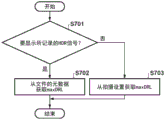
接着,将说明用于提供高光警告表示的操作。本实施例中的高光警告表示是使得用户能够在当前拍摄条件下识别图像中的“作为溢出高光的区域”或“几乎作为溢出高光的区域”的功能。注意,作为溢出高光的区域是亮度饱和的区域,因此很难通过图像处理来恢复该区域中的色调。因此,通过向用户通知作为溢出高光的区域和几乎作为溢出高光的区域,用户可以改变曝光条件,使得在溢出高光不是预期的情况下减少将变为溢出高光的区域。此外,在溢出高光是预期的情况下,可以确认预期区域是否将变为溢出高光,并且可以改变曝光条件以使得预期区域变为溢出高光。Next, the operation for providing the highlight warning indication will be explained. The highlight warning representation in the present embodiment is a function that enables the user to recognize an "area that is a blown highlight" or "an area that is almost a blown highlight" in the image under the current shooting conditions. Note that the area that is a spilled highlight is an area where the brightness is saturated, so it is difficult to restore the hue in this area by image processing. Therefore, by notifying the user of the areas that are and almost the areas that are blown highlights, the user can change the exposure conditions so that the areas that will become blown highlights are reduced if the blown highlights are not expected. In addition, in the case where the spill highlight is expected, it can be confirmed whether the expected area will become the spill highlight, and the exposure conditions can be changed so that the expected area becomes the spill highlight.
特别地,符合亮度被处理为绝对值的HDR标准的HDR图像存在与高光警告表示有关的特定问题。在SDR图像或者符合亮度以相对值表示的HDR标准的HDR图像的情况下,显示峰值亮度是与输出装置的能力相对应的值。因此,将接近于图像数据中的最大值(在位深度是8位的情况下为255)的值(例如,248)设置为阈值、并为值大于或等于阈值的像素提供高光警告就足够了。通过采用这种配置,总是可以为覆盖整个图像的动态范围的预定比例的高亮度范围(例如,动态范围的高亮度范围侧的2%)提供高光警告表示。In particular, HDR images conforming to the HDR standard in which luminance is processed as an absolute value have specific problems related to highlight warning representation. In the case of an SDR image or an HDR image conforming to the HDR standard in which luminance is expressed as a relative value, the display peak luminance is a value corresponding to the capability of the output device. Therefore, it is sufficient to set a value (eg, 248) close to the maximum value in the image data (255 in the case of an 8-bit bit depth) as the threshold, and provide a highlight warning for pixels with a value greater than or equal to the threshold . By adopting this configuration, a highlight warning indication can always be provided for a predetermined proportion of the high-brightness range (eg, 2% of the high-brightness range side of the dynamic range) covering the entire image's dynamic range.
然而,在符合诸如PQ方式等的、亮度被处理为绝对值的HDR标准的HDR图像的情况下,图像数据的值与固定显示亮度相对应。因此,存在不能通过基于固定阈值提供高光警告来获得期望结果的情况。例如,考虑在图5所示的示例中基于与第二拍摄模式下的峰值亮度44相对应的固定阈值来提供高光警告的情况。在这种情况下,与SDR图像相同,可以针对在第二拍摄模式下拍摄的HDR图像数据提供使用固定阈值的高光警告。然而,由于固定阈值大于峰值亮度43,因此对于在第一拍摄模式下拍摄的HDR图像数据,根本不会提供高光警告。为了处理这样的问题,在本实施例中使用基于maxDRL的阈值来提供高光警告。However, in the case of an HDR image conforming to the HDR standard in which the luminance is processed as an absolute value, such as the PQ method, the value of the image data corresponds to the fixed display luminance. Therefore, there are situations where the desired result cannot be obtained by providing a highlight warning based on a fixed threshold. For example, consider the case where the highlight warning is provided based on a fixed threshold corresponding to the
以下将使用图6和图7来说明根据本实施例的用于提供高光警告表示的操作。图6是将与基于HDR信号413提供高光警告表示相关的信号处理电路25的操作图示为功能块的图。如果在基于通过使用图3说明的处理而生成的HDR信号413进行显示时开启高光警告表示的提供,则信号处理电路25执行以下操作。注意,图6所示的功能块601~604中的一个或多个可以通过控制单元21执行ROM中所存储的程序来实现。The operation for providing the highlight warning indication according to the present embodiment will be described below using FIGS. 6 and 7 . FIG. 6 is a diagram illustrating, as functional blocks, the operation of the
在步骤S701中,亮度获取单元409判断是要显示存储单元26中存储的所记录的HDR信号、还是要显示诸如实时取景图像等的未记录(正在拍摄)的HDR信号。亮度获取单元409在判断为要显示所记录的HDR信号的情况下使处理进入步骤S702,并且在判断为要显示未记录的HDR信号的情况下使处理进入步骤S703。In step S701, the
在步骤S702中,阈值计算单元602获取maxDRL,该maxDRL的描述被包括在记录要显示的HDR信号的数据文件的元数据中。另外,在步骤S703中,阈值计算单元602从例如存储器28获取maxDRL,该maxDRL是亮度获取单元409从伽马选择单元408根据当前拍摄条件(拍摄模式和感光度)所选择的对比度调整曲线407获取的。然后,阈值计算单元602计算与maxDRL相对应的高光警告阈值。In step S702, the threshold
将说明高光警告阈值的计算方法的一个示例。在本实施例中,与针对SDR信号提供高光警告表示相同,使用作为一个感知均匀颜色空间并且由ITU-R BT.2100标准化的ICtCp颜色空间。假定maxSDR是SDR信号的可能最大值,并且thrS是要用于针对SDR信号提供高光警告的阈值(SDR信号阈值)。例如,假定:SDR信号的位深度是8位,并且maxSDR和thrS被分别预先设置为255和248,并被存储到例如控制单元21的ROM。这里,通过将给定像素X的RGB值(Xr、Xg、Xb)转换为ICtCp颜色空间中的值而获得的I值(亮度值)被表示为I(X)。这里,如果ΔI被定义为与maxSDR相对应的I值和与thrS相对应的I值之间的差,则ΔI可以根据下式1计算。An example of a calculation method of the highlight warning threshold will be explained. In this embodiment, the ICtCp color space, which is a perceptually homogeneous color space and standardized by ITU-R BT.2100, is used, as is the case for providing a highlight warning representation for the SDR signal. It is assumed that maxSDR is the maximum possible value of the SDR signal and thrS is the threshold to be used to provide a highlight warning for the SDR signal (SDR signal threshold). For example, it is assumed that the bit depth of the SDR signal is 8 bits, and maxSDR and thrS are preset to 255 and 248, respectively, and are stored in, for example, the ROM of the
ΔI=I(maxSDR)-I(thrS) 式1ΔI=I(maxSDR)-I(thrS)
阈值计算单元602根据下式2来计算与要用于HDR信号的高光警告阈值thrH1相对应的I值I(thrH1)。The threshold
I(thrH1)=I(maxDRL)-ΔI 式2I(thrH1)=I(maxDRL)-
此外,通过将I(thrH1)逆转换为RGB颜色空间中的值,可以计算出RGB值的阈值thrH1。Also, by inversely converting I(thrH1) to a value in the RGB color space, the threshold thrH1 for RGB values can be calculated.
以这种方式,使HDR图像的阈值和HDR图像中的最大值之间的差ΔI与SDR图像的阈值和SDR图像中的最大值之间的差ΔI相等。通过采用这种配置,提供高光警告的表示,使得开始高光警告的提供处的明度和图像的可能最大明度之间的差对于SDR图像和HDR图像是相同的。因此,无论图像是SDR图像还是HDR图像,在具有用户将明度感知为溢出高光的程度相同的明度水平的区域提供高光警告的表示。In this way, the difference ΔI between the threshold value of the HDR image and the maximum value in the HDR image is made equal to the difference ΔI between the threshold value of the SDR image and the maximum value in the SDR image. By employing this configuration, a representation of the highlight warning is provided such that the difference between the luminance at which the provision of the highlight warning is started and the maximum possible luminance of the image is the same for the SDR image and the HDR image. Thus, regardless of whether the image is an SDR image or an HDR image, a representation of the highlight warning is provided in areas with the same level of lightness that the user perceives lightness as blown out highlights.
接着,警告区域检测单元603(检测部件)通过对要显示的HDR信号应用阈值thrH1并进行阈值处理来检测高光警告对象区域(像素)。例如,警告区域检测单元603将具有大于或等于阈值thrH1的值的像素指定为警告对象像素。这里,警告区域检测单元603根据各像素是否是高光警告对象,来计算通过对HDR图像进行二值化而获得的警告图mapH。例如,图8B示出针对图8A所示的HDR图像获得的警告图mapH的示例。图8B示出作为警告对象的像素是1(白色)、以及并非作为警告对象的像素是0(黑色)的警告图mapH的示例。Next, the warning area detection unit 603 (detection means) detects a highlight warning object area (pixel) by applying a threshold value thrH1 to the HDR signal to be displayed and performing threshold value processing. For example, the warning
注意,在计算警告图mapH时,可以将阈值thrH1转换为RGB空间中的值,并且可以单独对HDR图像数据的R、G、B值进行阈值处理。在这种情况下,对于所有分量R、G、B,将具有大于或等于阈值的值的像素指定为警告对象像素。可选地,可以对HDR图像数据应用从RGB颜色空间到YCbCr颜色空间的转换,然后可以对亮度信号Y应用阈值thrH1。也可以根据其它方法进行阈值处理。Note that when calculating the warning map mapH, the threshold thrH1 can be converted to a value in RGB space, and the R, G, B values of the HDR image data can be individually thresholded. In this case, for all components R, G, B, a pixel having a value greater than or equal to the threshold value is designated as a warning object pixel. Optionally, a conversion from RGB color space to YCbCr color space may be applied to the HDR image data, and then a threshold thrH1 may be applied to the luminance signal Y. Thresholding can also be performed according to other methods.
警告表示单元604(显示控制部件)基于警告区域检测单元603所生成的警告图mapH来向HDR图像添加警告表示。用于提供警告表示的方法没有特别限制,并且可以使用允许视觉区分区域的任何方法。例如,可以在对象区域上以叠加状态(始终或周期性地)显示诸如斑马图案等的特定图案,可以将对象区域内的像素值(始终或周期性地)改变为特定值,或者可以以闪烁状态显示对象区域内的像素。这些仅仅是示例,并且可以使用允许视觉区分对象区域和非对象区域的任何方法。警告表示单元604可以通过在用作VRAM的存储器28的区域中写入图案数据、通过改变像素值等来实现高光警告表示。图8C示出已经提供基于图8B中的警告图mapH的高光警告表示的状态的示例。The warning representation unit 604 (display control means) adds a warning representation to the HDR image based on the warning map mapH generated by the warning
如以上说明的,根据本实施例,采用如下配置:在针对符合亮度值被处理为绝对值的HDR标准的HDR图像数据来提供高光警告表示的情况下,使用与图像数据中的最大值相对应的阈值。因此,即使在峰值亮度根据拍摄模式有所不同的情况下,也可以提供适当的高光警告表示。As explained above, according to the present embodiment, a configuration is adopted in which, in the case where the highlight warning indication is provided for the HDR image data conforming to the HDR standard in which the luminance value is processed as an absolute value, the use corresponding to the maximum value in the image data is used. the threshold value. Therefore, even when the peak brightness differs depending on the shooting mode, an appropriate highlight warning indication can be provided.
第二实施例Second Embodiment
接着,将说明本发明的第二实施例。本实施例在阈值计算单元602的操作方面与第一实施例不同。因此,以下将说明如何计算本实施例中的高光警告阈值thrH2。Next, a second embodiment of the present invention will be described. The present embodiment differs from the first embodiment in the operation of the threshold
在本实施例中,阈值计算单元602以比率与SDR信号的最大输出值maxSDR和高光警告阈值thrS之间的比率相同的方式来计算针对HDR信号的高光警告阈值。In the present embodiment, the
阈值计算单元602从控制单元21的ROM获取maxSDR和thrS,并根据下式3来计算比率r。The threshold
r=thrS/maxSDR 式3r=thrS/
此外,阈值计算单元602根据下式4来计算针对HDR信号的高光警告阈值thrH2。Further, the threshold
thrH2=r×maxDRL 式4thrH2=r×maxDRL
通过使用高光警告阈值thrH2,可以在SDR信号和HDR信号各自中,向相对于相应最大输出值具有相同或更高比率的值的像素提供高光警告表示。By using the highlight warning threshold thrH2, a highlight warning indication can be provided to pixels having the same or higher ratio of values relative to the corresponding maximum output value in each of the SDR signal and the HDR signal.
第三实施例Third Embodiment
接着,将说明本发明的第三实施例。本实施例在阈值计算单元602的操作方面与第一实施例和第二实施例不同。因此,以下将说明如何计算本实施例中的高光警告阈值thrH3。Next, a third embodiment of the present invention will be explained. The present embodiment differs from the first and second embodiments in the operation of the threshold
在本实施例中,阈值计算单元602在伽马转换处理之前使用信号值,即来自图像传感器10的信号值。In the present embodiment, the threshold
图9示出由伽马转换单元405应用于SDR图像和HDR图像的对比度调整曲线407(伽马曲线)的输入/输出特性的示例。在图9中,Val2表示图像传感器10的饱和信号值。Val1表示与针对SDR信号的高光警告阈值thrS相对应的图像传感器10的信号值。FIG. 9 shows an example of the input/output characteristics of the contrast adjustment curve 407 (gamma curve) applied by the
阈值计算单元602计算在输入值Val1由应用于HDR图像的对比度调整曲线407进行转换时所获得的输出值作为针对HDR信号的高光警告阈值thrH3。The threshold
通过使用这种高光警告阈值thrH3,可以在SDR信号和HDR信号这两者中向伽马转换之前的信号值在相同范围内的像素提供高光警告表示。因此,可以针对SDR信号和HDR信号的相同区域提供高光警告。By using such a highlight warning threshold thrH3, a highlight warning indication can be provided in both the SDR signal and the HDR signal to pixels whose signal values before gamma conversion are in the same range. Thus, highlight warnings can be provided for the same area of the SDR signal and the HDR signal.
第四实施例Fourth Embodiment
接着,将说明本发明的第四实施例。本实施例在阈值计算单元602的操作方面与第一实施例至第三实施例不同。因此,以下将说明如何计算本实施例中的高光警告阈值thrH4。Next, a fourth embodiment of the present invention will be described. The present embodiment differs from the first to third embodiments in the operation of the threshold
在第一实施例至第三实施例中,使用通过不同计算方法获得的高光警告阈值。然而,这些高光警告阈值可以组合使用。在本实施例中,阈值计算单元602使用在第一实施例至第三实施例中计算出的阈值中的两个或更多个来计算高光警告阈值。In the first to third embodiments, the highlight warning thresholds obtained by different calculation methods are used. However, these highlight warning thresholds can be used in combination. In the present embodiment, the threshold
这里,将说明通过对第一实施例至第三实施例中所计算出的阈值进行加权相加并进一步添加常数来计算高光警告阈值的情况。当常数表示为α1、α2、α3和β1时,阈值计算单元602根据下式5来计算高光警告阈值thrH4。Here, a case where the highlight warning threshold is calculated by weighted addition of the thresholds calculated in the first to third embodiments and further adding a constant will be described. When the constants are expressed as α1 , α2 , α3 , and β1 , the threshold
thrH4=α1×thrH1+α2×thrH2+α3×thrH3+β1 式5thrH4=α1×thrH1+α2×thrH2+α3×thrH3+
通过调整作为被提供至阈值的权重的常数α1、α2和α3以及其余的常数β1,可以实现以良好平衡考虑了伽马转换后的输出动态范围和伽马转换前的图像传感器10的动态范围的高光警告表示。这些常数可以例如通过试错来设置。By adjusting the constants α1 , α2 , and α3 as weights provided to the thresholds and the remaining constant β1 , it is possible to achieve a dynamic range in which the output dynamic range after gamma conversion and the dynamic range of the
第五实施例Fifth Embodiment
接着,将描述本发明的第五实施例。在第一实施例至第四实施例中,说明了用于针对HDR信号提供高光警告表示的方法。存在要显示所生成的HDR信号的显示器仅可与SDR信号兼容的情况。在本实施例中,实现了根据HDR信号的显示环境的高光警告表示。Next, a fifth embodiment of the present invention will be described. In the first to fourth embodiments, a method for providing a highlight warning representation for an HDR signal has been described. There are cases where a display to display the generated HDR signal is only compatible with the SDR signal. In this embodiment, a highlight warning indication according to the display environment of the HDR signal is realized.
使用阈值计算单元602、根据第一实施例至第四实施例其中之一来计算针对要显示的HDR信号的高光警告阈值,并且进一步地,使用警告区域检测单元603预先计算相应的警告图mapH。如果HDR信号的显示目的地仅可与SDR信号兼容,则警告表示单元604进行HDR信号到SDR信号的色调映射。注意,虽然使用显像时所进行的伽马转换的逆将HDR信号转换为线性信号、并进一步进行用于显像SDR信号的伽马转换等的方法可以被视为色调映射方法的一个示例,但可以使用不同的方法。The threshold
此外,警告表示单元604针对所创建的SDR信号中的、由警告图mapH表示的高光区域提供高光警告表示。注意,如果显示器27例如是外部装置,则可以通过在显示器27连接时与控制单元21进行通信来获取显示目的地的能力。此外,可以采用如下配置:在通过用户配置选择了SDR显示的情况下,进行色调映射。Furthermore, the
根据本实施例,即使在用于显示HDR信号的设备不可与HDR信号兼容并且只能将HDR信号显示为SDR信号的情况下,也可以在与HDR信号显示在可与HDR信号兼容的显示设备上的情况相同的区域实现高光警告表示。According to the present embodiment, even in the case where a device for displaying HDR signals is not compatible with HDR signals and can only display HDR signals as SDR signals, it is possible to display HDR signals on a display device compatible with HDR signals The same area of the situation implements the highlight warning representation.
第六实施例Sixth Embodiment
在第一实施例至第四实施例中,基于一个高光警告阈值提供一种类型的高光警告表示。在本实施例中,使用多个阈值来提供多个分级的高光警告表示。In the first to fourth embodiments, one type of highlight warning representation is provided based on a highlight warning threshold. In this embodiment, multiple thresholds are used to provide multiple graded highlight warning representations.
只要满足分级关系,用于计算多个阈值的方法就不受特别限制。例如,可以组合在第一实施例至第四实施例中获得的阈值。这里,将说明用于使用一种方法(例如,第一实施例中所说明的方法)以分级方式计算阈值的方法。The method for calculating the plurality of thresholds is not particularly limited as long as the hierarchical relationship is satisfied. For example, the threshold values obtained in the first to fourth embodiments may be combined. Here, a method for calculating the threshold value in a hierarchical manner using a method (eg, the method described in the first embodiment) will be described.
例如,阈值计算单元602可以通过增加在第一实施例中减去ΔI的次数来计算具有不同分级的高光警告阈值thrH6_1和thrH6_2,如式6和式7中所示。这里,I(thrH6_1)等于第一实施例中所使用的I(thrH1)。For example, the
I(thrH6_1)=I(maxDRL)-ΔI 式6I(thrH6_1)=I(maxDRL)-
I(thrH6_2)=I(thrH6_1)-ΔI 式7I(thrH6_2)=I(thrH6_1)-ΔI Formula 7
通过将I(thrH6_1)和I(thrH6_2)逆转换到RGB颜色空间,可以计算出RGB值的阈值thrH6_1和thrH6_2。The thresholds thrH6_1 and thrH6_2 for RGB values can be calculated by inversely converting I(thrH6_1) and I(thrH6_2) to the RGB color space.
警告区域检测单元603针对各阈值创建警告图。注意,可以以从最大阈值开始的顺序生成警告图,并且相对于已被判断为警告对象的像素作为非警告对象的像素的情况下可以生成针对下一阈值的警告图。The warning
基于各警告图,警告表示单元604提供根据分级在视觉上有所不同的高光警告表示。Based on each warning map, the
在本实施例中,作为一个示例已经说明了使用根据第一实施例的方法确定两个阈值并使用这两个阈值的配置。然而,阈值的数量可以是三个或更多个,并且用于确定多个分级的阈值的方法不限于根据第一实施例的方法。例如,可以适当地组合和使用第一实施例至第四实施例中所说明的方法。此外,可以采用如下配置:在如第五实施例那样进行HDR信号到SDR信号的色调映射之后,通过应用多个阈值来提供多个分级的高光警告表示。In the present embodiment, the configuration in which two threshold values are determined using the method according to the first embodiment and the two threshold values are used has been described as an example. However, the number of thresholds may be three or more, and the method for determining a plurality of hierarchical thresholds is not limited to the method according to the first embodiment. For example, the methods described in the first to fourth embodiments can be appropriately combined and used. Furthermore, a configuration may be adopted in which a plurality of graded highlight warning representations are provided by applying a plurality of thresholds after tone mapping of the HDR signal to the SDR signal as in the fifth embodiment.
根据本实施例,可以针对高光部分提供多个分级的警告表示,并且用户可以更详细地识别图像中的高光的分布。According to the present embodiment, a plurality of graded warning representations can be provided for highlight parts, and the user can identify the distribution of highlights in the image in more detail.
其它实施例Other embodiments
本发明的实施例还可以通过如下的方法来实现,即,通过网络或者各种存储介质将执行上述实施例的功能的软件(程序)提供给系统或装置,该系统或装置的计算机或是中央处理单元(CPU)、微处理单元(MPU)读出并执行程序的方法。The embodiments of the present invention can also be implemented by the following method, that is, providing software (programs) for performing the functions of the above-mentioned embodiments to a system or device through a network or various storage media, and the computer of the system or device or the central A method in which a processing unit (CPU) and a micro processing unit (MPU) read and execute programs.
虽然已经参考典型实施例说明了本发明,但是应当理解,本发明不限于所公开的典型实施例。以下权利要求书的范围应被给予最广泛的理解,以便包含所有这样的修改以及等同结构和功能。While the present invention has been described with reference to exemplary embodiments, it is to be understood that the invention is not limited to the disclosed exemplary embodiments. The scope of the following claims is to be accorded the broadest interpretation so as to encompass all such modifications and equivalent structures and functions.
Claims (14)
Applications Claiming Priority (2)
| Application Number | Priority Date | Filing Date | Title |
|---|---|---|---|
| JP2019-085797 | 2019-04-26 | ||
| JP2019085797A JP7373299B2 (en) | 2019-04-26 | 2019-04-26 | Image processing device and its control method |
Publications (2)
| Publication Number | Publication Date |
|---|---|
| CN111866399A true CN111866399A (en) | 2020-10-30 |
| CN111866399B CN111866399B (en) | 2022-06-28 |
Family
ID=72921753
Family Applications (1)
| Application Number | Title | Priority Date | Filing Date |
|---|---|---|---|
| CN202010320609.2A Active CN111866399B (en) | 2019-04-26 | 2020-04-22 | Image processing apparatus, control method thereof, and computer readable medium |
Country Status (3)
| Country | Link |
|---|---|
| US (1) | US11196938B2 (en) |
| JP (1) | JP7373299B2 (en) |
| CN (1) | CN111866399B (en) |
Families Citing this family (3)
| Publication number | Priority date | Publication date | Assignee | Title |
|---|---|---|---|---|
| CN117678232A (en) * | 2021-07-16 | 2024-03-08 | 索尼集团公司 | Imaging equipment and imaging methods |
| JP7652749B2 (en) | 2022-11-11 | 2025-03-27 | キヤノン株式会社 | IMAGE PROCESSING APPARATUS, IMAGE PROCESSING METHOD, AND IMAGING APPARATUS |
| CN116129806B (en) * | 2022-12-28 | 2025-04-15 | 厦门天马显示科技有限公司 | Display panel control method and control device, storage medium and electronic device |
Citations (11)
| Publication number | Priority date | Publication date | Assignee | Title |
|---|---|---|---|---|
| JP2010278890A (en) * | 2009-05-29 | 2010-12-09 | Canon Inc | Image forming apparatus and image forming method |
| CN101981694A (en) * | 2008-02-25 | 2011-02-23 | Rjs科技公司 | Systems and methods for high dynamic range image sensor sensing arrays |
| US20110310116A1 (en) * | 2009-03-06 | 2011-12-22 | Koninklijke Philips Electronics N.V. | Method for converting input image data into output image data, image conversion unit for converting input image data into output image data, image processing apparatus, display device |
| CN102984462A (en) * | 2011-09-06 | 2013-03-20 | 奥林巴斯映像株式会社 | Image pickup apparatus |
| US20150078661A1 (en) * | 2013-08-26 | 2015-03-19 | Disney Enterprises, Inc. | High dynamic range and tone mapping imaging techniques |
| CN104869370A (en) * | 2014-02-21 | 2015-08-26 | 佳能株式会社 | Image processing apparatus and image processing method |
| CN106056629A (en) * | 2016-05-31 | 2016-10-26 | 南京大学 | High dynamic range imaging method for removing ghosts through moving object detection and extension |
| JP2018036502A (en) * | 2016-08-31 | 2018-03-08 | エルジー ディスプレイ カンパニー リミテッド | Image processing circuit, image conversion device, image display device, and image processing method |
| US20180089811A1 (en) * | 2016-09-27 | 2018-03-29 | Canon Kabushiki Kaisha | Image processing apparatus, and image processing method |
| CN108063898A (en) * | 2016-11-07 | 2018-05-22 | 株式会社电装 | Image forming apparatus |
| CN109155844A (en) * | 2016-05-16 | 2019-01-04 | Lg 电子株式会社 | Image processing equipment and the image processing method for using the image processing equipment |
Family Cites Families (10)
| Publication number | Priority date | Publication date | Assignee | Title |
|---|---|---|---|---|
| JP6420540B2 (en) | 2013-02-04 | 2018-11-07 | キヤノン株式会社 | Image processing apparatus, control method therefor, program, and storage medium |
| JP6331882B2 (en) * | 2014-08-28 | 2018-05-30 | ソニー株式会社 | Transmitting apparatus, transmitting method, receiving apparatus, and receiving method |
| JP2017139613A (en) | 2016-02-03 | 2017-08-10 | キヤノン株式会社 | Image processing apparatus, image processing method, and program |
| US9998720B2 (en) * | 2016-05-11 | 2018-06-12 | Mediatek Inc. | Image processing method for locally adjusting image data of real-time image |
| EP3319013A1 (en) * | 2016-11-03 | 2018-05-09 | Thomson Licensing | Method and device for estimating cast shadow regions and/or highlight regions in images |
| JP6659178B2 (en) | 2017-03-01 | 2020-03-04 | キヤノン株式会社 | Image processing apparatus and image processing method |
| KR102361885B1 (en) * | 2017-03-28 | 2022-02-11 | 삼성전자주식회사 | Electronic apparatus and controlling method thereof |
| JP7071137B2 (en) * | 2018-01-26 | 2022-05-18 | キヤノン株式会社 | Electronic devices and their control methods |
| CN110839129A (en) * | 2018-08-17 | 2020-02-25 | Oppo广东移动通信有限公司 | Image processing method, device and mobile terminal |
| US11054973B1 (en) * | 2020-06-01 | 2021-07-06 | Apple Inc. | User interfaces for managing media |
-
2019
- 2019-04-26 JP JP2019085797A patent/JP7373299B2/en active Active
-
2020
- 2020-04-22 CN CN202010320609.2A patent/CN111866399B/en active Active
- 2020-04-24 US US16/858,248 patent/US11196938B2/en active Active
Patent Citations (11)
| Publication number | Priority date | Publication date | Assignee | Title |
|---|---|---|---|---|
| CN101981694A (en) * | 2008-02-25 | 2011-02-23 | Rjs科技公司 | Systems and methods for high dynamic range image sensor sensing arrays |
| US20110310116A1 (en) * | 2009-03-06 | 2011-12-22 | Koninklijke Philips Electronics N.V. | Method for converting input image data into output image data, image conversion unit for converting input image data into output image data, image processing apparatus, display device |
| JP2010278890A (en) * | 2009-05-29 | 2010-12-09 | Canon Inc | Image forming apparatus and image forming method |
| CN102984462A (en) * | 2011-09-06 | 2013-03-20 | 奥林巴斯映像株式会社 | Image pickup apparatus |
| US20150078661A1 (en) * | 2013-08-26 | 2015-03-19 | Disney Enterprises, Inc. | High dynamic range and tone mapping imaging techniques |
| CN104869370A (en) * | 2014-02-21 | 2015-08-26 | 佳能株式会社 | Image processing apparatus and image processing method |
| CN109155844A (en) * | 2016-05-16 | 2019-01-04 | Lg 电子株式会社 | Image processing equipment and the image processing method for using the image processing equipment |
| CN106056629A (en) * | 2016-05-31 | 2016-10-26 | 南京大学 | High dynamic range imaging method for removing ghosts through moving object detection and extension |
| JP2018036502A (en) * | 2016-08-31 | 2018-03-08 | エルジー ディスプレイ カンパニー リミテッド | Image processing circuit, image conversion device, image display device, and image processing method |
| US20180089811A1 (en) * | 2016-09-27 | 2018-03-29 | Canon Kabushiki Kaisha | Image processing apparatus, and image processing method |
| CN108063898A (en) * | 2016-11-07 | 2018-05-22 | 株式会社电装 | Image forming apparatus |
Non-Patent Citations (2)
| Title |
|---|
| 吴雨祥等: "基于高动态范围图像技术的高光误差补偿方法", 《红外技术》 * |
| 王柳等: "基于自适应条纹投影的高反光物体三维面形测量", 《应用光学》 * |
Also Published As
| Publication number | Publication date |
|---|---|
| JP7373299B2 (en) | 2023-11-02 |
| JP2020182179A (en) | 2020-11-05 |
| CN111866399B (en) | 2022-06-28 |
| US11196938B2 (en) | 2021-12-07 |
| US20200344400A1 (en) | 2020-10-29 |
Similar Documents
| Publication | Publication Date | Title |
|---|---|---|
| US7706674B2 (en) | Device and method for controlling flash | |
| JP7157714B2 (en) | Image processing device and its control method | |
| US7598990B2 (en) | Image signal processing system and electronic imaging device | |
| JP5169318B2 (en) | Imaging apparatus and imaging method | |
| WO2015025740A1 (en) | Control device, control method, and electronic device | |
| JP7227719B2 (en) | IMAGE PROCESSING DEVICE, IMAGING DEVICE, IMAGE PROCESSING METHOD, AND PROGRAM | |
| US11798143B2 (en) | Image processing apparatus and control method thereof | |
| JP2014022998A (en) | Image processor and control method thereof | |
| JP2024122091A (en) | Information processing device and control method thereof | |
| US11245852B2 (en) | Capturing apparatus for generating two types of images for display from an obtained captured image based on scene luminance and exposure | |
| US9036046B2 (en) | Image processing apparatus and method with white balance correction | |
| JP2020178292A (en) | Imaging device and its control method, program | |
| JP2019071568A (en) | Image processing apparatus, image processing method, program, and storage medium | |
| CN111866399B (en) | Image processing apparatus, control method thereof, and computer readable medium | |
| JP6741881B2 (en) | Image processing device, imaging device, image processing method, and program | |
| CN102238394B (en) | Image processing apparatus, control method thereof, and image-capturing apparatus | |
| JP7397640B2 (en) | Image processing device and image processing method | |
| JP5316923B2 (en) | Imaging apparatus and program thereof | |
| CN107979718A (en) | Image processing equipment, image processing method and storage medium | |
| JP4735051B2 (en) | Imaging device | |
| US11641525B2 (en) | Image capturing apparatus capable of displaying live view image high in visibility, method of controlling image capturing apparatus, and storage medium | |
| JP2006332936A (en) | Imaging device | |
| JP7370762B2 (en) | Imaging device and its control method | |
| WO2025249363A1 (en) | Image processing device and image processing method | |
| JP2006345301A (en) | Imaging apparatus |
Legal Events
| Date | Code | Title | Description |
|---|---|---|---|
| PB01 | Publication | ||
| PB01 | Publication | ||
| SE01 | Entry into force of request for substantive examination | ||
| SE01 | Entry into force of request for substantive examination | ||
| GR01 | Patent grant | ||
| GR01 | Patent grant |