CN111845737A - Curve target identification method of intelligent vehicle and danger level judgment mechanism thereof - Google Patents
Curve target identification method of intelligent vehicle and danger level judgment mechanism thereof Download PDFInfo
- Publication number
- CN111845737A CN111845737A CN202010552525.1A CN202010552525A CN111845737A CN 111845737 A CN111845737 A CN 111845737A CN 202010552525 A CN202010552525 A CN 202010552525A CN 111845737 A CN111845737 A CN 111845737A
- Authority
- CN
- China
- Prior art keywords
- vehicle
- target
- lane
- distance
- curve
- Prior art date
- Legal status (The legal status is an assumption and is not a legal conclusion. Google has not performed a legal analysis and makes no representation as to the accuracy of the status listed.)
- Pending
Links
- 238000000034 method Methods 0.000 title claims abstract description 26
- 230000007246 mechanism Effects 0.000 title claims abstract description 13
- 238000012545 processing Methods 0.000 claims abstract description 10
- 239000011159 matrix material Substances 0.000 claims description 18
- 238000005259 measurement Methods 0.000 claims description 18
- 238000001914 filtration Methods 0.000 claims description 13
- 230000001133 acceleration Effects 0.000 claims description 6
- 230000008569 process Effects 0.000 claims description 6
- 230000007704 transition Effects 0.000 claims description 6
- 239000003086 colorant Substances 0.000 claims description 4
- 230000005284 excitation Effects 0.000 claims description 3
- 230000006870 function Effects 0.000 claims description 3
- 238000005070 sampling Methods 0.000 claims description 3
- 230000035484 reaction time Effects 0.000 abstract description 3
- 230000001052 transient effect Effects 0.000 abstract description 3
- 238000010586 diagram Methods 0.000 description 2
- 230000000694 effects Effects 0.000 description 2
- 230000004075 alteration Effects 0.000 description 1
- 230000006399 behavior Effects 0.000 description 1
- 230000009286 beneficial effect Effects 0.000 description 1
- 230000007613 environmental effect Effects 0.000 description 1
- 230000003993 interaction Effects 0.000 description 1
- 238000012986 modification Methods 0.000 description 1
- 230000004048 modification Effects 0.000 description 1
- 230000008447 perception Effects 0.000 description 1
- 238000011160 research Methods 0.000 description 1
- 238000006467 substitution reaction Methods 0.000 description 1
Images


Classifications
-
- B—PERFORMING OPERATIONS; TRANSPORTING
- B60—VEHICLES IN GENERAL
- B60W—CONJOINT CONTROL OF VEHICLE SUB-UNITS OF DIFFERENT TYPE OR DIFFERENT FUNCTION; CONTROL SYSTEMS SPECIALLY ADAPTED FOR HYBRID VEHICLES; ROAD VEHICLE DRIVE CONTROL SYSTEMS FOR PURPOSES NOT RELATED TO THE CONTROL OF A PARTICULAR SUB-UNIT
- B60W30/00—Purposes of road vehicle drive control systems not related to the control of a particular sub-unit, e.g. of systems using conjoint control of vehicle sub-units
- B60W30/08—Active safety systems predicting or avoiding probable or impending collision or attempting to minimise its consequences
- B60W30/095—Predicting travel path or likelihood of collision
-
- B—PERFORMING OPERATIONS; TRANSPORTING
- B60—VEHICLES IN GENERAL
- B60W—CONJOINT CONTROL OF VEHICLE SUB-UNITS OF DIFFERENT TYPE OR DIFFERENT FUNCTION; CONTROL SYSTEMS SPECIALLY ADAPTED FOR HYBRID VEHICLES; ROAD VEHICLE DRIVE CONTROL SYSTEMS FOR PURPOSES NOT RELATED TO THE CONTROL OF A PARTICULAR SUB-UNIT
- B60W40/00—Estimation or calculation of non-directly measurable driving parameters for road vehicle drive control systems not related to the control of a particular sub unit, e.g. by using mathematical models
- B60W40/02—Estimation or calculation of non-directly measurable driving parameters for road vehicle drive control systems not related to the control of a particular sub unit, e.g. by using mathematical models related to ambient conditions
- B60W40/06—Road conditions
- B60W40/072—Curvature of the road
-
- B—PERFORMING OPERATIONS; TRANSPORTING
- B60—VEHICLES IN GENERAL
- B60W—CONJOINT CONTROL OF VEHICLE SUB-UNITS OF DIFFERENT TYPE OR DIFFERENT FUNCTION; CONTROL SYSTEMS SPECIALLY ADAPTED FOR HYBRID VEHICLES; ROAD VEHICLE DRIVE CONTROL SYSTEMS FOR PURPOSES NOT RELATED TO THE CONTROL OF A PARTICULAR SUB-UNIT
- B60W50/00—Details of control systems for road vehicle drive control not related to the control of a particular sub-unit, e.g. process diagnostic or vehicle driver interfaces
- B60W50/0097—Predicting future conditions
-
- B—PERFORMING OPERATIONS; TRANSPORTING
- B60—VEHICLES IN GENERAL
- B60W—CONJOINT CONTROL OF VEHICLE SUB-UNITS OF DIFFERENT TYPE OR DIFFERENT FUNCTION; CONTROL SYSTEMS SPECIALLY ADAPTED FOR HYBRID VEHICLES; ROAD VEHICLE DRIVE CONTROL SYSTEMS FOR PURPOSES NOT RELATED TO THE CONTROL OF A PARTICULAR SUB-UNIT
- B60W50/00—Details of control systems for road vehicle drive control not related to the control of a particular sub-unit, e.g. process diagnostic or vehicle driver interfaces
- B60W50/08—Interaction between the driver and the control system
- B60W50/14—Means for informing the driver, warning the driver or prompting a driver intervention
-
- B—PERFORMING OPERATIONS; TRANSPORTING
- B60—VEHICLES IN GENERAL
- B60W—CONJOINT CONTROL OF VEHICLE SUB-UNITS OF DIFFERENT TYPE OR DIFFERENT FUNCTION; CONTROL SYSTEMS SPECIALLY ADAPTED FOR HYBRID VEHICLES; ROAD VEHICLE DRIVE CONTROL SYSTEMS FOR PURPOSES NOT RELATED TO THE CONTROL OF A PARTICULAR SUB-UNIT
- B60W60/00—Drive control systems specially adapted for autonomous road vehicles
- B60W60/001—Planning or execution of driving tasks
- B60W60/0027—Planning or execution of driving tasks using trajectory prediction for other traffic participants
-
- B—PERFORMING OPERATIONS; TRANSPORTING
- B60—VEHICLES IN GENERAL
- B60W—CONJOINT CONTROL OF VEHICLE SUB-UNITS OF DIFFERENT TYPE OR DIFFERENT FUNCTION; CONTROL SYSTEMS SPECIALLY ADAPTED FOR HYBRID VEHICLES; ROAD VEHICLE DRIVE CONTROL SYSTEMS FOR PURPOSES NOT RELATED TO THE CONTROL OF A PARTICULAR SUB-UNIT
- B60W50/00—Details of control systems for road vehicle drive control not related to the control of a particular sub-unit, e.g. process diagnostic or vehicle driver interfaces
- B60W2050/0001—Details of the control system
- B60W2050/0019—Control system elements or transfer functions
- B60W2050/0028—Mathematical models, e.g. for simulation
- B60W2050/0031—Mathematical model of the vehicle
-
- B—PERFORMING OPERATIONS; TRANSPORTING
- B60—VEHICLES IN GENERAL
- B60W—CONJOINT CONTROL OF VEHICLE SUB-UNITS OF DIFFERENT TYPE OR DIFFERENT FUNCTION; CONTROL SYSTEMS SPECIALLY ADAPTED FOR HYBRID VEHICLES; ROAD VEHICLE DRIVE CONTROL SYSTEMS FOR PURPOSES NOT RELATED TO THE CONTROL OF A PARTICULAR SUB-UNIT
- B60W2520/00—Input parameters relating to overall vehicle dynamics
- B60W2520/10—Longitudinal speed
-
- B—PERFORMING OPERATIONS; TRANSPORTING
- B60—VEHICLES IN GENERAL
- B60W—CONJOINT CONTROL OF VEHICLE SUB-UNITS OF DIFFERENT TYPE OR DIFFERENT FUNCTION; CONTROL SYSTEMS SPECIALLY ADAPTED FOR HYBRID VEHICLES; ROAD VEHICLE DRIVE CONTROL SYSTEMS FOR PURPOSES NOT RELATED TO THE CONTROL OF A PARTICULAR SUB-UNIT
- B60W2554/00—Input parameters relating to objects
- B60W2554/40—Dynamic objects, e.g. animals, windblown objects
-
- B—PERFORMING OPERATIONS; TRANSPORTING
- B60—VEHICLES IN GENERAL
- B60W—CONJOINT CONTROL OF VEHICLE SUB-UNITS OF DIFFERENT TYPE OR DIFFERENT FUNCTION; CONTROL SYSTEMS SPECIALLY ADAPTED FOR HYBRID VEHICLES; ROAD VEHICLE DRIVE CONTROL SYSTEMS FOR PURPOSES NOT RELATED TO THE CONTROL OF A PARTICULAR SUB-UNIT
- B60W2554/00—Input parameters relating to objects
- B60W2554/80—Spatial relation or speed relative to objects
- B60W2554/801—Lateral distance
-
- B—PERFORMING OPERATIONS; TRANSPORTING
- B60—VEHICLES IN GENERAL
- B60W—CONJOINT CONTROL OF VEHICLE SUB-UNITS OF DIFFERENT TYPE OR DIFFERENT FUNCTION; CONTROL SYSTEMS SPECIALLY ADAPTED FOR HYBRID VEHICLES; ROAD VEHICLE DRIVE CONTROL SYSTEMS FOR PURPOSES NOT RELATED TO THE CONTROL OF A PARTICULAR SUB-UNIT
- B60W2554/00—Input parameters relating to objects
- B60W2554/80—Spatial relation or speed relative to objects
- B60W2554/802—Longitudinal distance
Landscapes
- Engineering & Computer Science (AREA)
- Automation & Control Theory (AREA)
- Transportation (AREA)
- Mechanical Engineering (AREA)
- Human Computer Interaction (AREA)
- Physics & Mathematics (AREA)
- Mathematical Physics (AREA)
- Traffic Control Systems (AREA)
Abstract
The invention discloses a curve target identification method of an intelligent vehicle, which comprises a starting vehicle, a key target identification unit M2, a curve key target identification unit M3; the invention also provides a system for judging the danger level of the curve target of the intelligent vehicle, which comprises data acquisition, data processing and danger marking; the invention overcomes the problem of transient disorder of the system caused by the phenomenon that the front target is disordered or lost when the vehicle enters a curve; meanwhile, a judgment mechanism and a display scheme of the front target danger level are provided, so that the surrounding traffic condition of the driver can be effectively reminded, and sufficient reaction time is provided for the driver.
Description
Technical Field
The invention relates to the technical field of intelligent automobiles, in particular to a method for identifying a curve target of an intelligent vehicle, and also relates to a danger level judgment mechanism of the method for identifying the curve target of the intelligent vehicle.
Background
An intelligent automobile is a cross frontier science technology which integrates environmental perception, decision planning and control execution, and is also an important component of an Intelligent Transportation System (ITS). Aiming at the existing intelligent vehicle, the intelligent vehicle is generally formed by combining advanced sensor radar, a camera, a controller and other equipment, and is integrated with advanced network technology to realize the interaction of people, vehicles, roads and traffic environment information. The accurate recognition of the front key target vehicle is one of the most basic driving behaviors, and has important influence on road traffic efficiency, driving safety and the like.
In a stable lane, a Kalman filter of a yaw angular velocity is established based on a vehicle dynamics linear model and an online estimation of a road curvature is realized according to a document 1 (TaoXinlong, Mixueyu, Wang Chang. On the basis, whether the rear center of the front target vehicle is in the lane of the vehicle is taken as a judgment basis, and an identification model of the system target is established. However, since the vehicle is a complex nonlinear system, certain errors necessarily exist in the estimation of the target realized by using the linear kalman filter, and a specific method for judging the danger level of the front key target vehicle and a realization mechanism thereof are not provided.
For the problem of identifying the key target in front of the road, usually on the road section of a curve, the phenomenon that the target vehicle is disordered or lost is easy to happen, and the vehicle is also accelerated or decelerated suddenly in order to meet the tracking performance, so that the lateral stability of the vehicle is reduced suddenly, and the driving safety of the vehicle is seriously threatened.
Disclosure of Invention
The invention aims to provide a curve target identification method of an intelligent vehicle and a danger level judgment mechanism thereof, and the invention applies an extended Kalman filtering theory to carry out the identification research of key targets of a front curve. The method comprises the steps of establishing a transverse, longitudinal and transverse non-linear three-degree-of-freedom vehicle model, designing an extended Kalman filter of the transverse and longitudinal transverse angular velocity, and realizing the on-line real-time estimation of the road curvature. Meanwhile, a curve key target recognition model is established and a key target judgment basis is given on the basis of the estimation value. Finally, a danger level judgment mechanism of a key target vehicle is designed, and dangerous vehicles are judged in advance to deal with complex road conditions so as to solve the problems in the background technology.
In order to achieve the purpose, the invention provides the following technical scheme: a method for identifying a curve target of an intelligent vehicle specifically comprises the following steps:
s1: starting the vehicle, starting the vehicle-mounted sensor M1 to work, detecting the information of the area in front of the vehicle, and transmitting the information to the key target identification unit through the vehicle bus;
s2: the key target identification unit M2 receives the M1 transmitted multiple target vehicles i (i ═ 1, 2...... n) existing in the area ahead of the vehicle, and the transverse distance d between each target and the vehiclexi(i 1, 2.... n), the longitudinal distance d of each target from the vehicleyi(i 1, 2.... cndot., n), a direction angle θ of each target to the own vehiclei(i 1, 2.... n), the relative speed v of each target to the own vehiclerel,i(i ═ 1,2,..., n) and vehicle body state information;
2.1: based on a nonlinear three-degree-of-freedom vehicle model, a yaw angular velocity extended Kalman filter is established, and the process is as follows:
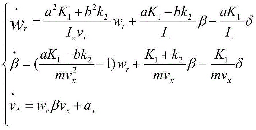
on the basis of a traditional linear two-degree-of-freedom vehicle model, the longitudinal vehicle speed of the vehicle is introduced, and a nonlinear three-degree-of-freedom model is established by combining the yaw angular speed and the centroid slip angle, so that a state space equation and a measurement equation of the model are as follows:


wherein, wrThe yaw angular velocity; beta is the centroid slip angle; is a front wheel corner; v. of xIs the longitudinal vehicle speed; a is the distance of the centroid from the front axis; b is the distance of the centroid from the rear axis; k1 is front axle equivalent yaw stiffness; k2 is the rear axle equivalent cornering stiffness; i iszIs the moment of inertia about the z-axis; m is the vehicle mass; a isxIs the longitudinal acceleration; a isyIs the lateral acceleration;
2.2: therefore, the yaw angular velocity, the longitudinal vehicle speed and the mass center slip angle of the automobile are estimated by a Kalman filtering (EKF) algorithm based on a three-degree-of-freedom vehicle model:
establishing a state equation and a measurement equation of the system:
in the formula f (x)t,ut,wt)、h(xt,vt) Respectively, a state space equation and a measurement equation, and x (t) is a state variable of the system; y (t) is the measurement output; u (t) is a control variable; w (t) is system excitation noise; v (t) is measurement noise;
2.3: model linearization:

Φ(t)=eF(t)Δt≈I+F(t)·Δt
wherein F (t), H (t) are nonlinear functions f (x) respectivelyt,ut,wt) And h (x)t,vt) Solving a Jacobian matrix of the partial derivatives of the state variables; phi (t) is a state transition matrix; i is an identity matrix; Δ t is the sampling time;
2.4: the prediction and update process of the extended kalman filter is as follows:
the state prediction equation: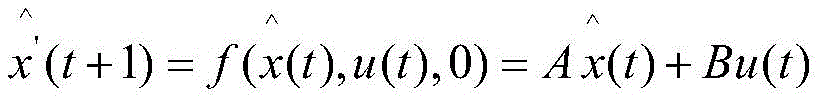
error covariance prediction equation: p' (t +1) ═ Φ (t) p (t) Φ (t)T+Q
Calculating a Kalman gain: k (t) ═ P' (t) HT(t)(H(t)P'(t)HT(t)+R)-1
In the formula: is a predictor variable at time t + 1; A. b is a state variable coefficient matrix of discretization of the prediction equation; k (t) is a transition variable at time t; h (t) is a Jacobian matrix for partial derivatives of the state variables h (x (t), v (t)); r is a covariance matrix of observation noise;
Updating the estimate by measurement:
error covariance update procedure: p (t) ([ I-k (t) h (t)) ] P' (t)
Above, the state variable x ═ wr,β,]T(ii) a The output variable is y ═ ay]The controlled variable is u [, a [ ]x]TR, P, Q, I assigning initial values according to the original definition, respectively;
s3: identification of curve key targets:
establishing a filtering model of the yaw angular velocity by using an extended Kalman filter to realize real-time online estimation of the curvature radius of the vehicle running track;
when driving on a curve, the radius of curvature may be via w of the filterrTo obtain:
taking the target i in front of the lane as an example, knowing that the vehicle is running on a curve, the target i is laterally offset from the center line of the lane by a distance doff,i: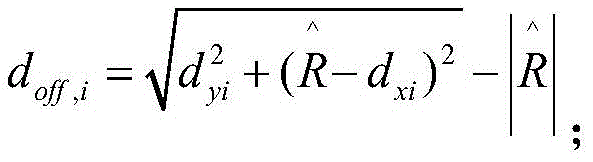
In the formula dxi、dyi(i 1, 2......, n) as above, obtained by M1; the inverse of the curvature of the road at a target vehicle i (i ═ 1, 2.... n.), which is obtained by real-time online estimation of a yaw rate filtering model established by an extended Kalman filter;
according to the lateral distance d of the target i relative to the central line of the laneoff,iAnd determining whether the target i is located in the lane, wherein the judgment is as follows:
if it is And d isoff,i> 0 and | doff,i|>dthreshold: the target vehicle is positioned on the right side of the lane;
if it is And d isoff,i< 0 and | doff,i|>dthreshold: the target vehicle is positioned on the left side of the lane;
if it is And d isoff,i> 0 and | doff,i|>dthreshold: the target vehicle is positioned on the left side of the lane;
If it is And d isoff,i< 0 and | doff,i|>dthreshold: the target vehicle is positioned on the right side of the lane;
if | doff,i|≤dthresholdAnd then: the target vehicle is positioned in the lane;
in the above judgment bases, dthreshold(m) is a set threshold value, usually takes a half lane width or less, and can be set according to actual conditions;
s4: a display unit M3 for receiving the target vehicle i (i ═ 1,2,...... multidot.n) in the three directions of the front, the front left and the front right, which are transmitted by the M2, through the automobile bus; then, each target vehicle is associated with itself according to the target vehicleTransverse distance d of vehiclexi(i 1, 2.... n), the longitudinal distance d of each target from the vehicleyi(i 1, 2.... cndot., n), a direction angle θ of each target to the own vehiclei(i 1,2, a.. n, n), and vehicle body state information, and deciding one target of each lane (left lane, self lane, right lane) which is closest to the self vehicle, wherein the target is respectively arranged in the left front area, the right front area and the right front area of the display;
4.1: a display area division for displaying the left front on the vehicle-mounted display when the target is divided into the left lane of the M2 range, and displaying the right front on the vehicle-mounted display when the target is divided into the right lane of the M2 range, otherwise, displaying the right front area;
4.2: judging the danger level by calculating the longitudinal distance of the target and the time distance tau between longitudinal vehicles ttc: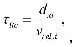 Based on the above, dividing the danger level; the smaller the relative distance and the time interval of the longitudinal workshop, the higher the danger level;
area directly in front:
dxie (180, + ∞) m, class 0; dxi∈(150,180]m, grade 1; dxi∈(90,150]m, 2 grade; v. ofrel,i< -30(m/s) or τttc2.5s, grade 3; tau isttc< 1.5s, level 4;
left and right front regions:
dxie (100, + ∞) m, class 0; dxiE (90, + ∞) m, level 1; v. ofrel,i< -30(m/s) or τttc2 < 2.5s, grade 2; and τttc< 1.5s, grade 3;
4.3: the vehicle-mounted display receives the target danger level information, and the target vehicle danger level information is displayed in a layered mode or different colors or sounds and the like.
The invention also provides a danger level judgment mechanism of the curve target of the intelligent vehicle, which comprises the following steps:
A. data acquisition: acquiring related information in front of a vehicle body through a vehicle-mounted sensor radar;
B. data processing: receiving all target data output by a radar from an automobile bus, and finally obtaining a target closest to the automobile in the same lane and targets closest to the automobile in adjacent lanes (namely left and right lanes of the automobile lane) through a series of filtering, verifying and combing;
C. and (4) danger marking: after the data processing of step B, the vehicle-mounted display identifies the target information obtained from the target processing system of S2 by color level or sound level.
Compared with the prior art, the invention has the beneficial effects that:
1. the invention provides a method for improving the stability of an intelligent vehicle, which solves the problem of transient disorder of a system caused by the fact that a front target is disordered or lost when a vehicle enters a curve; meanwhile, a judgment mechanism and a display scheme of the front target danger level are provided, so that the surrounding traffic condition of the driver can be effectively reminded, and sufficient reaction time is provided for the driver.
Drawings
FIG. 1 is a block diagram of a risk level determination mechanism of the present invention;
FIG. 2 is a flow chart of an identification method of the present invention;
FIG. 3 is a schematic diagram of a method for displaying a risk level according to the present invention.
Detailed Description
The technical solutions in the embodiments of the present invention will be clearly and completely described below with reference to fig. 1 to 3 in the embodiments of the present invention, and it is obvious that the described embodiments are only a part of the embodiments of the present invention, and not all embodiments. All other embodiments, which can be derived by a person skilled in the art from the embodiments given herein without making any creative effort, shall fall within the protection scope of the present invention.
Referring to fig. 2, the present invention provides a technical solution: a method for identifying a curve target of an intelligent vehicle specifically comprises the following steps:
S1: starting the vehicle, starting the vehicle-mounted sensor M1 to work, detecting the information of the area in front of the vehicle, and transmitting the information to the key target identification unit through the vehicle bus;
s2: the key target identification unit M2 receives the M1 transmitted multiple target vehicles i (i ═ 1, 2...... n) existing in the area ahead of the vehicle, and the transverse distance d between each target and the vehiclexi(i 1, 2.... n), the longitudinal distance d of each target from the vehicleyi(i 1, 2.... cndot., n), a direction angle θ of each target to the own vehiclei(i 1, 2.... n), the relative speed v of each target to the own vehiclerel,i(i ═ 1,2,..., n) and vehicle body state information;
2.1: based on a nonlinear three-degree-of-freedom vehicle model, a yaw angular velocity extended Kalman filter is established, and the process is as follows:
on the basis of a traditional linear two-degree-of-freedom vehicle model, the longitudinal vehicle speed of the vehicle is introduced, and a nonlinear three-degree-of-freedom model is established by combining the yaw angular speed and the centroid slip angle, so that a state space equation and a measurement equation of the model are as follows:

wherein, wrThe yaw angular velocity; beta is the centroid slip angle; is a front wheel corner; v. ofxIs the longitudinal vehicle speed; a is the distance of the centroid from the front axis; b is the distance of the centroid from the rear axis; k1 is front axle equivalent yaw stiffness; k2 is the rear axle equivalent cornering stiffness; i is zIs the moment of inertia about the z-axis; m is the vehicle mass; a isxIs the longitudinal acceleration; a isyIs the lateral acceleration;
2.2: therefore, the yaw angular velocity, the longitudinal vehicle speed and the mass center slip angle of the automobile are estimated by a Kalman filtering (EKF) algorithm based on a three-degree-of-freedom vehicle model:
establishing a state equation and a measurement equation of the system:
in the formula f (x)t,ut,wt)、h(xt,vt) Respectively, a state space equation and a measurement equation, and x (t) is a state variable of the system; y (t) is the measurement output; u (t) is a control variable; w (t) is system excitation noise; v (t) is measurement noise;
2.3: model linearization:

Φ(t)=eF(t)Δt≈I+F(t)·Δt
wherein F (t), H (t) are nonlinear functions f (x) respectivelyt,ut,wt) And h (x)t,vt) Solving a Jacobian matrix of the partial derivatives of the state variables; phi (t) is a state transition matrix; i is an identity matrix; Δ t is the sampling time;
2.4: the prediction and update process of the extended kalman filter is as follows:
the state prediction equation:
error covariance prediction equation: p' (t +1) ═ Φ (t) p (t) Φ (t)T+Q
Calculating a Kalman gain: k (t) ═ P' (t) HT(t)(H(t)P'(t)HT(t)+R)-1
In the formula: is a predictor variable at time t + 1; A. b is a state variable coefficient matrix of discretization of the prediction equation; k (t) is a transition variable at time t; h (t) is a Jacobian matrix for partial derivatives of the state variables h (x (t), v (t)); r is a covariance matrix of observation noise;
Updating the estimate by measurement:
error covariance update procedure: p (t) ([ I-k (t) h (t)) ] P' (t)
Above, the state variable x ═ wr,β,]T(ii) a The output variable is y ═ ay]The controlled variable is u [, a [ ]x]TR, P, Q, I assigning initial values according to the original definition, respectively;
s3: identification of curve key targets:
establishing a filtering model of the yaw angular velocity by using an extended Kalman filter to realize real-time online estimation of the curvature radius of the vehicle running track;
when driving on a curve, the radius of curvature may be via w of the filterrTo obtain: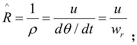
taking the target i in front of the lane as an example, knowing that the vehicle is running on a curve, the target i is laterally offset from the center line of the lane by a distance doff,i:
In the formula dxi、dyi(i 1, 2......, n) as above, obtained by M1; the inverse of the curvature of the road at a target vehicle i (i ═ 1, 2.... n.), which is obtained by real-time online estimation of a yaw rate filtering model established by an extended Kalman filter;
according to the lateral distance d of the target i relative to the central line of the laneoff,iAnd determining whether the target i is located in the lane, wherein the judgment is as follows:
if it is And d isoff,i> 0 and | doff,i|>dthreshold: the target vehicle is positioned on the right side of the lane;
if it is And d isoff,i< 0 and | doff,i|>dthreshold: the target vehicle is positioned on the left side of the lane;
if it is And d isoff,i> 0 and | doff,i|>dthreshold: the target vehicle is positioned on the left side of the lane;
If it is And d isoff,i< 0 and | doff,i|>dthreshold: the target vehicle is positioned on the right side of the lane;
if | doff,i|≤dthresholdAnd then: the target vehicle is positioned in the lane;
in the above judgment bases, dthreshold(m) is a set threshold value, usually takes a half lane width or less, and can be set according to actual conditions;
s4: a display unit M3 for receiving the target vehicle i (i ═ 1,2,...... multidot.n) in the three directions of the front, the front left and the front right, which are transmitted by the M2, through the automobile bus; then, according to the lateral distance d between each target and the self vehicle of the target vehiclexi(i 1, 2.... n), the longitudinal distance d of each target from the vehicleyi(i 1, 2.... cndot., n), a direction angle θ of each target to the own vehiclei(i 1, 2.... cndot., n), and vehicle body state information, deciding one target of each lane (left lane, own lane, right lane) closest to the own vehicle, and respectively placing the targets in the left front area, the right front area and the right front area of the display, as shown in fig. 3;
4.1: a display area division for displaying the left front on the vehicle-mounted display when the target is divided into the left lane of the M2 range, and displaying the right front on the vehicle-mounted display when the target is divided into the right lane of the M2 range, otherwise, displaying the right front area;
4.2: judging the danger level by calculating the longitudinal distance of the target and the time distance tau between longitudinal vehicles ttc: Based on which the danger level is divided(ii) a The smaller the relative distance and the time interval of the longitudinal workshop, the higher the danger level;
area directly in front:
dxie (180, + ∞) m, class 0; dxi∈(150,180]m, grade 1; dxi∈(90,150]m, 2 grade; v. ofrel,i< -30(m/s) or τttc2.5s, grade 3; tau isttc< 1.5s, level 4;
left and right front regions:
dxie (100, + ∞) m, class 0; dxiE (90, + ∞) m, level 1; v. ofrel,i< -30(m/s) or τttc2 < 2.5s, grade 2; and τttc< 1.5s, grade 3;
4.3: the vehicle-mounted display receives the target danger level information, and the target vehicle danger level information is displayed in a layered mode or different colors or sounds and the like.
As shown in fig. 1, the present invention further provides a danger level determination mechanism for a curve target of an intelligent vehicle, comprising the following steps:
A. data acquisition: acquiring related information in front of a vehicle body through a vehicle-mounted sensor radar;
B. data processing: receiving all target data output by a radar from an automobile bus, and finally obtaining a target closest to the automobile in the same lane and targets closest to the automobile in adjacent lanes (namely left and right lanes of the automobile lane) through a series of filtering, verifying and combing;
C. and (4) danger marking: after the data processing of step B, the vehicle-mounted display identifies the target information obtained from the target processing system of S2 by color level or sound level.
In summary, the following steps: according to the scheme, the vehicle-mounted sensor is used for acquiring the workshop state information in real time; judging the target of the lane and the adjacent lane according to the target information and the state of the vehicle; and making a relevant prompt on a corresponding vehicle-mounted display according to the position of the target relative to the vehicle.
By acquiring workshop information, a yaw angular velocity extended Kalman filter is established, and the curvature radius of the curve is estimated on line, so that the effect of stably tracking a front target is achieved.
The vehicle-mounted display makes related prompts, and the display can remind the danger degree of the target through the same color or multiple colors or the buzzer through sound according to the processed information.
And according to the tracking effect, providing a judgment basis for the position of the target, namely the position of the lane where the target is located.
And obtaining information according to the display, and giving a method for judging the danger level of the target vehicle according to the time distance and the relative distance between the vehicles.
The invention provides a method for improving the stability of an intelligent vehicle, which solves the problem of transient disorder of a system caused by the fact that a front target is disordered or lost when a vehicle enters a curve; meanwhile, a judgment mechanism and a display scheme of the front target danger level are provided, so that the surrounding traffic condition of the driver can be effectively reminded, and sufficient reaction time is provided for the driver.
Although embodiments of the present invention have been shown and described, it will be appreciated by those skilled in the art that changes, modifications, substitutions and alterations can be made in these embodiments without departing from the principles and spirit of the invention, the scope of which is defined in the appended claims and their equivalents.
Claims (2)
1. A method for identifying a curve target of an intelligent vehicle is characterized by comprising the following steps:
s1: starting the vehicle, starting the vehicle-mounted sensor M1 to work, detecting the information of the area in front of the vehicle, and transmitting the information to the key target identification unit through the vehicle bus;
s2: the key target identification unit M2 receives the M1 transmitted multiple target vehicles i (i ═ 1, 2...... n) existing in the area ahead of the vehicle, and the transverse distance d between each target and the vehiclexi(i 1, 2.... n), the longitudinal distance d of each target from the vehicleyi(i 1, 2.... cndot., n), a direction angle θ of each target to the own vehiclei(i 1, 2.... n), the relative speed v of each target to the own vehiclerel,i(i ═ 1,2,..., n) and vehicle body state information;
2.1: based on a nonlinear three-degree-of-freedom vehicle model, a yaw angular velocity extended Kalman filter is established, and the process is as follows:
On the basis of a traditional linear two-degree-of-freedom vehicle model, the longitudinal vehicle speed of the vehicle is introduced, and a nonlinear three-degree-of-freedom model is established by combining the yaw angular speed and the centroid slip angle, so that a state space equation and a measurement equation of the model are as follows:


wherein, wrThe yaw angular velocity; beta is the centroid slip angle; is a front wheel corner; v. ofxIs the longitudinal vehicle speed; a is the distance of the centroid from the front axis; b is the distance of the centroid from the rear axis; k1 is front axle equivalent yaw stiffness; k2 is the rear axle equivalent cornering stiffness; i iszIs the moment of inertia about the z-axis; m is the vehicle mass; a isxIs the longitudinal acceleration; a isyIs the lateral acceleration;
2.2: therefore, the yaw angular velocity, the longitudinal vehicle speed and the mass center slip angle of the automobile are estimated by a Kalman filtering (EKF) algorithm based on a three-degree-of-freedom vehicle model:
establishing a state equation and a measurement equation of the system:
in the formula f (x)t,ut,wt)、h(xt,vt) Respectively, a state space equation and a measurement equation, and x (t) is a state variable of the system; y (t) is the measurement output; u (t) is a control variable; w (t) is system excitation noise; v (t) is measurement noise;
2.3: model linearization:

Φ(t)=eF(t)Δt≈I+F(t)·Δt
wherein F (t), H (t) are nonlinear functions f (x) respectivelyt,ut,wt) And h (x)t,vt) Solving a Jacobian matrix of the partial derivatives of the state variables; phi (t) is a state transition matrix; i is an identity matrix; Δ t is the sampling time;
2.4: the prediction and update process of the extended kalman filter is as follows:
the state prediction equation:
error covariance prediction equation: p' (t +1) ═ Φ (t) p (t) Φ (t)T+Q
Calculating a Kalman gain: k (t) ═ P' (t) HT(t)(H(t)P'(t)HT(t)+R)-1
In the formula: is a predictor variable at time t + 1; A. b is a state variable coefficient matrix of discretization of the prediction equation; k (t) is a transition variable at time t; h (t) is a Jacobian matrix for partial derivatives of the state variables h (x (t), v (t)); r is a covariance matrix of observation noise;
updating the estimate by measurement: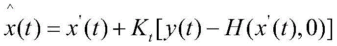
error covariance update procedure: p (t) ([ I-k (t) h (t)) ] P' (t)
Above, the state variable x ═ wr,β,]T(ii) a The output variable is y ═ ay]The controlled variable is u [, a [ ]x]TR, P, Q, I assigning initial values according to the original definition, respectively;
s3: identification of curve key targets:
establishing a filtering model of the yaw angular velocity by using an extended Kalman filter to realize real-time online estimation of the curvature radius of the vehicle running track;
when driving on a curve, the radius of curvature may be via w of the filterrTo obtain: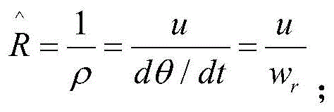
taking the target i in front of the lane as an example, knowing that the vehicle is running on a curve, the target i is laterally offset from the center line of the lane by a distance doff,i:
In the formula dxi、dyi(i 1, 2......, n) as above, obtained by M1; the inverse of the curvature of the road at a target vehicle i (i ═ 1, 2.... n.), which is obtained by real-time online estimation of a yaw rate filtering model established by an extended Kalman filter;
According to the lateral distance d of the target i relative to the central line of the laneoff,iAnd determining whether the target i is located in the lane, wherein the judgment is as follows:
if it is And d isoff,i> 0 and | doff,i|>dthreshold: the target vehicle is positioned on the right side of the lane;
if it is And d isoff,i< 0 and | doff,i|>dthreshold: the target vehicle is positioned on the left side of the lane;
if it is And d isoff,i> 0 and | doff,i|>dthreshold: the target vehicle is positioned on the left side of the lane;
if it is And d isoff,i< 0 and | doff,i|>dthreshold: the target vehicle is positioned on the right side of the lane;
if | doff,i|≤dthresholdAnd then: the target vehicle is positioned in the lane;
in the above judgment bases, dthreshold(m) is a set threshold value, usually takes a half lane width or less, and can be set according to actual conditions;
s4: a display unit M3 for receiving the target vehicle i (i ═ 1,2,...... multidot.n) in the three directions of the front, the front left and the front right, which are transmitted by the M2, through the automobile bus; then, according to the lateral distance d between each target and the self vehicle of the target vehiclexi(i 1, 2.... n), the longitudinal distance d of each target from the vehicleyi(i 1, 2.... cndot., n), a direction angle θ of each target to the own vehiclei(i 1,2, a.. n, n), and vehicle body state information, and deciding one target of each lane (left lane, self lane, right lane) which is closest to the self vehicle, wherein the target is respectively arranged in the left front area, the right front area and the right front area of the display;
4.1: a display area division for displaying the left front on the vehicle-mounted display when the target is divided into the left lane of the M2 range, and displaying the right front on the vehicle-mounted display when the target is divided into the right lane of the M2 range, otherwise, displaying the right front area;
4.2: judging the danger level by calculating the longitudinal distance of the target and the time distance tau between longitudinal vehiclesttc: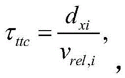 Based on the above, dividing the danger level; the smaller the relative distance and the time interval of the longitudinal workshop, the higher the danger level;
area directly in front:
dxie (180, + ∞) m, class 0; dxi∈(150,180]m, grade 1; dxi∈(90,150]m, 2 grade; v. ofrel,i< -30(m/s) or τttc2.5s, grade 3; tau isttc< 1.5s, level 4;
left and right front regions:
dxie (100, + ∞) m, class 0; dxiE (90, + ∞) m, level 1; v. ofrel,i< -30(m/s) or τttc2 < 2.5s, grade 2; and τttc< 1.5s, grade 3;
4.3: the vehicle-mounted display receives the target danger level information, and the target vehicle danger level information is displayed in a layered mode or different colors or sounds and the like.
2. A danger level judging mechanism of a curve target of a smart vehicle according to claim 1, characterized in that: the method specifically comprises the following steps:
A. data acquisition: acquiring related information in front of a vehicle body through a vehicle-mounted sensor radar;
B. data processing: receiving all target data output by a radar from an automobile bus, and finally obtaining a target closest to the automobile in the same lane and targets closest to the automobile in adjacent lanes (namely left and right lanes of the automobile lane) through a series of filtering, verifying and combing;
C. And (4) danger marking: after the data processing of step B, the vehicle-mounted display identifies the target information obtained from the target processing system of S2 by color level or sound level.
Priority Applications (1)
| Application Number | Priority Date | Filing Date | Title |
|---|---|---|---|
| CN202010552525.1A CN111845737A (en) | 2020-06-17 | 2020-06-17 | Curve target identification method of intelligent vehicle and danger level judgment mechanism thereof |
Applications Claiming Priority (1)
| Application Number | Priority Date | Filing Date | Title |
|---|---|---|---|
| CN202010552525.1A CN111845737A (en) | 2020-06-17 | 2020-06-17 | Curve target identification method of intelligent vehicle and danger level judgment mechanism thereof |
Publications (1)
| Publication Number | Publication Date |
|---|---|
| CN111845737A true CN111845737A (en) | 2020-10-30 |
Family
ID=72987276
Family Applications (1)
| Application Number | Title | Priority Date | Filing Date |
|---|---|---|---|
| CN202010552525.1A Pending CN111845737A (en) | 2020-06-17 | 2020-06-17 | Curve target identification method of intelligent vehicle and danger level judgment mechanism thereof |
Country Status (1)
| Country | Link |
|---|---|
| CN (1) | CN111845737A (en) |
Cited By (5)
| Publication number | Priority date | Publication date | Assignee | Title |
|---|---|---|---|---|
| CN112550287A (en) * | 2020-12-16 | 2021-03-26 | 重庆大学 | Driving risk assessment method for structured road |
| CN113428141A (en) * | 2021-07-15 | 2021-09-24 | 东风汽车集团股份有限公司 | Intelligent detection method and system for timely response of emergency cut-in of front vehicle |
| CN114463964A (en) * | 2020-11-09 | 2022-05-10 | 刘腾腾 | Vehicle AEB curve barrier screening method |
| CN114895661A (en) * | 2021-12-14 | 2022-08-12 | 合肥哈工轩辕智能科技有限公司 | Real-time path planning method and device under intelligent driving scene |
| CN115593404A (en) * | 2021-07-09 | 2023-01-13 | 博泰车联网科技(上海)股份有限公司(Cn) | Vehicle control method, device, vehicle and computer readable storage medium |
Citations (8)
| Publication number | Priority date | Publication date | Assignee | Title |
|---|---|---|---|---|
| CN104182991A (en) * | 2014-08-15 | 2014-12-03 | 辽宁工业大学 | Vehicle running state estimation method and vehicle running state estimation device |
| CN106114511A (en) * | 2016-07-21 | 2016-11-16 | 辽宁工业大学 | A kind of automobile cruise system core target identification method |
| CN106250591A (en) * | 2016-07-21 | 2016-12-21 | 辽宁工业大学 | A kind of motoring condition method of estimation considering to roll impact |
| CN108357498A (en) * | 2018-02-07 | 2018-08-03 | 北京新能源汽车股份有限公司 | Vehicle state parameter determination method and device and automobile |
| CN109895699A (en) * | 2019-03-11 | 2019-06-18 | 汉腾汽车有限公司 | A kind of system and method indicating Vehicle target and degree of danger |
| CN110386152A (en) * | 2019-06-17 | 2019-10-29 | 江铃汽车股份有限公司 | The human-computer interaction display control method and system driven based on L2 grades of intelligence navigators |
| CN110803160A (en) * | 2019-11-14 | 2020-02-18 | 吉林大学 | Automobile backward anti-collision control system and control method |
| CN110940981A (en) * | 2019-11-29 | 2020-03-31 | 径卫视觉科技(上海)有限公司 | Method for judging whether position of target in front of vehicle is in lane |
-
2020
- 2020-06-17 CN CN202010552525.1A patent/CN111845737A/en active Pending
Patent Citations (8)
| Publication number | Priority date | Publication date | Assignee | Title |
|---|---|---|---|---|
| CN104182991A (en) * | 2014-08-15 | 2014-12-03 | 辽宁工业大学 | Vehicle running state estimation method and vehicle running state estimation device |
| CN106114511A (en) * | 2016-07-21 | 2016-11-16 | 辽宁工业大学 | A kind of automobile cruise system core target identification method |
| CN106250591A (en) * | 2016-07-21 | 2016-12-21 | 辽宁工业大学 | A kind of motoring condition method of estimation considering to roll impact |
| CN108357498A (en) * | 2018-02-07 | 2018-08-03 | 北京新能源汽车股份有限公司 | Vehicle state parameter determination method and device and automobile |
| CN109895699A (en) * | 2019-03-11 | 2019-06-18 | 汉腾汽车有限公司 | A kind of system and method indicating Vehicle target and degree of danger |
| CN110386152A (en) * | 2019-06-17 | 2019-10-29 | 江铃汽车股份有限公司 | The human-computer interaction display control method and system driven based on L2 grades of intelligence navigators |
| CN110803160A (en) * | 2019-11-14 | 2020-02-18 | 吉林大学 | Automobile backward anti-collision control system and control method |
| CN110940981A (en) * | 2019-11-29 | 2020-03-31 | 径卫视觉科技(上海)有限公司 | Method for judging whether position of target in front of vehicle is in lane |
Cited By (5)
| Publication number | Priority date | Publication date | Assignee | Title |
|---|---|---|---|---|
| CN114463964A (en) * | 2020-11-09 | 2022-05-10 | 刘腾腾 | Vehicle AEB curve barrier screening method |
| CN112550287A (en) * | 2020-12-16 | 2021-03-26 | 重庆大学 | Driving risk assessment method for structured road |
| CN115593404A (en) * | 2021-07-09 | 2023-01-13 | 博泰车联网科技(上海)股份有限公司(Cn) | Vehicle control method, device, vehicle and computer readable storage medium |
| CN113428141A (en) * | 2021-07-15 | 2021-09-24 | 东风汽车集团股份有限公司 | Intelligent detection method and system for timely response of emergency cut-in of front vehicle |
| CN114895661A (en) * | 2021-12-14 | 2022-08-12 | 合肥哈工轩辕智能科技有限公司 | Real-time path planning method and device under intelligent driving scene |
Similar Documents
| Publication | Publication Date | Title |
|---|---|---|
| CN111845737A (en) | Curve target identification method of intelligent vehicle and danger level judgment mechanism thereof | |
| CN112733270B (en) | System and method for predicting vehicle running track and evaluating risk degree of track deviation | |
| US11643080B2 (en) | Trailing vehicle positioning system based on detected pressure zones | |
| CN112298179B (en) | Control method and system for automatic following of four-wheel drive vehicle | |
| CN106114511B (en) | A kind of automobile cruise system core target identification method | |
| Winstead et al. | Estimation of road grade and vehicle mass via model predictive control | |
| KR101320223B1 (en) | Method and system for assisting a driver when parking or manoeuvring a motor vehicle | |
| US11731661B2 (en) | Systems and methods for imminent collision avoidance | |
| CN108447308A (en) | A kind of intersection vehicles risk of collision prediction technique and system based on bus or train route collaboration | |
| EP3666612A1 (en) | Vehicle control device | |
| CN106250591A (en) | A kind of motoring condition method of estimation considering to roll impact | |
| CN109436085A (en) | A kind of wire-controlled steering system gearratio control method based on driving style | |
| US20180286222A1 (en) | Vehicle identifying device | |
| CN114852099B (en) | Method for predicting lane changing behavior of motor vehicle | |
| JP2022552938A (en) | In-vehicle cluster tracking system | |
| CN111599166B (en) | Method and system for interpreting traffic signals and negotiating signalized intersections | |
| US20050278112A1 (en) | Process for predicting the course of a lane of a vehicle | |
| CN120589030B (en) | Automatic driving path optimization control system integrating environment perception and prediction | |
| LeBlanc et al. | A warning and intervention system to prevent road-departure accidents | |
| CN119117007A (en) | Vehicle lateral control method and system, vehicle-mounted communication device and vehicle | |
| US11731700B2 (en) | Friction compensation for vehicle system control | |
| CN114291071A (en) | Method and system for judging vehicle stability control active intervention opportunity, readable storage medium and vehicle | |
| Wang et al. | Racing driver modeling based on driving behavior | |
| CN114274968A (en) | Vehicle control method and device, computing equipment and storage medium | |
| Bonfitto et al. | A DATA-DRIVEN METHOD FOR VEHICLE SPEED ESTIMATION. |
Legal Events
| Date | Code | Title | Description |
|---|---|---|---|
| PB01 | Publication | ||
| PB01 | Publication | ||
| SE01 | Entry into force of request for substantive examination | ||
| SE01 | Entry into force of request for substantive examination | ||
| RJ01 | Rejection of invention patent application after publication |
Application publication date: 20201030 |
|
| RJ01 | Rejection of invention patent application after publication |