CN111833437A - A method of creating 3D documents - Google Patents
A method of creating 3D documents Download PDFInfo
- Publication number
- CN111833437A CN111833437A CN202010654693.1A CN202010654693A CN111833437A CN 111833437 A CN111833437 A CN 111833437A CN 202010654693 A CN202010654693 A CN 202010654693A CN 111833437 A CN111833437 A CN 111833437A
- Authority
- CN
- China
- Prior art keywords
- dimensional
- utility item
- model
- creating
- determined
- Prior art date
- Legal status (The legal status is an assumption and is not a legal conclusion. Google has not performed a legal analysis and makes no representation as to the accuracy of the status listed.)
- Pending
Links
Images


Classifications
-
- G—PHYSICS
- G06—COMPUTING OR CALCULATING; COUNTING
- G06T—IMAGE DATA PROCESSING OR GENERATION, IN GENERAL
- G06T17/00—Three dimensional [3D] modelling, e.g. data description of 3D objects
Landscapes
- Physics & Mathematics (AREA)
- Engineering & Computer Science (AREA)
- Computer Graphics (AREA)
- Geometry (AREA)
- Software Systems (AREA)
- General Physics & Mathematics (AREA)
- Theoretical Computer Science (AREA)
- Processing Or Creating Images (AREA)
Abstract
本发明公开了一种创建三维文档的方法,确定现有二维文档中的实用物品的至少一个图示的图像参数,将实用物品的3D模型与具有所确定的图像参数的二维图像对示,并且,基于二维图示和3D模型与来自二维图示的确定图像参数的比较,获得附加信息,其与3D模型一起形成三维文档。该过程允许分析现有二维文档中的图示,以便从中获得附加信息,然后可以将其叠加在3D模型的任意视图上,为了能够容易地确定图像参数,在二维图示和3D模型中选择多个对应点,并且改变图像参数直到二维图示和3D模型对齐,为此目的,可以建立用于确定充分对准的合适标准。
The invention discloses a method for creating a three-dimensional document. The image parameters of at least one illustration of a practical item in the existing two-dimensional document are determined, and the 3D model of the practical item is displayed with the two-dimensional image having the determined image parameters. and, based on the comparison of the two-dimensional representation and the 3D model with the determined image parameters from the two-dimensional representation, additional information is obtained, which together with the 3D model forms a three-dimensional document. This process allows to analyze the diagrams in existing 2D documents in order to obtain additional information from them, which can then be superimposed on any view of the 3D model. A number of corresponding points are selected, and image parameters are varied until the two-dimensional representation and the 3D model are aligned, for which purpose suitable criteria for determining adequate alignment can be established.
Description
技术领域technical field
本发明涉及厨具领域,具体是一种创建三维文档的方法。The invention relates to the field of kitchenware, in particular to a method for creating a three-dimensional document.
背景技术Background technique
在大多数情况下,诸如手册,操作手册,组装说明,维修说明,培训文件等文档,对应于从家用电器,玩具,机器和机器组件到高度复杂的技术设备的各种实用物品。这样的文档通常包含实用程序文章的各种二维图示,实用程序文章的用户将基于该二维图示来理解实用程序文章的功能或接收使用该实用程序文章的指令。图示可以是简单视图,等轴测图,或甚至是实用物品视图的照片。印刷文件中的这种图示必然是实用物品的各种视图的二维表示。因此,当使用文档时,实用程序文章的用户必须将二维视图转移到实际的三维实用程序文章,这是一个非常复杂的心理挑战,并且对于许多人来说,根本没有三维转化能力。In most cases, documents such as manuals, operating manuals, assembly instructions, repair instructions, training documents, etc., correspond to practical items ranging from household appliances, toys, machines and machine components to highly complex technical equipment. Such documents typically contain various two-dimensional illustrations of the utility article based on which a user of the utility article will understand the functionality of the utility article or receive instructions to use the utility article. Illustrations can be simple views, isometrics, or even photographs of useful object views. Such illustrations in printed documents are necessarily two-dimensional representations of various views of the utility item. Therefore, when working with documents, users of utility articles have to transfer the 2D view to the actual 3D utility article, a very complex psychological challenge and, for many, no 3D translation capability at all.
这种情况可以通过使用三维形式的文档来改进,其中实用物品以三维方式表示,例如在显示单元上,实用物品的视图可任意改变,可以使用增强现实来实现进一步的改进,增强现实通常被理解为一个人对现实的实际感知,特别是被看到,听到或感觉到的,以便扩展或补充额外信息。该附加信息同样可以在视觉上,声学上或触觉上传达给人。例如,使用记录单元记录实用物品,例如智能电话或平板电脑的数码相机,3D扫描仪等,并且实用物品的记录视图实时补充有附加信息,通过将其叠加在记录和显示的图像上或通过回放声学信息。此外,目前存在用于以三维方式提供实用物品的文档的方法,也使用增强现实。然而,创建实用物品的三维文档是一项非常复杂、耗时的任务,特别是当需要三维动画时,也可能实时地(例如在增强现实中)也需要三维动画。这需要经验丰富的3D设计师和专业的动画软件产品。因此,到目前为止尚未建立三维文档或增强现实文档。This situation can be improved by using documentation in three-dimensional form, where utility items are represented in three dimensions, e.g. on a display unit, the view of utility items can be changed arbitrarily, and further improvements can be achieved using augmented reality, which is generally understood For a person's actual perception of reality, especially what is seen, heard or felt, in order to expand or supplement additional information. This additional information can likewise be conveyed to the person visually, acoustically or tactilely. For example, a utility item is recorded using a recording unit, such as a digital camera for a smartphone or tablet, a 3D scanner, etc., and the recorded view of the utility item is supplemented with additional information in real-time, either by superimposing it on the recorded and displayed image or by playback acoustic information. Furthermore, there are currently methods for providing documentation of utility items in three dimensions, also using augmented reality. However, creating 3D documentation of useful objects is a very complex and time-consuming task, especially when 3D animation is required, possibly also in real-time (eg in augmented reality). This requires experienced 3D designers and professional animation software products. Therefore, no three-dimensional or augmented reality documentation has been created so far.
发明内容SUMMARY OF THE INVENTION
本发明的目的在于提供一种创建三维文档的方法,以解决背景技术中提出的问题。为实现上述目的,本发明提供如下技术方案;The purpose of the present invention is to provide a method for creating a three-dimensional document, so as to solve the problems raised in the background art. To achieve the above object, the present invention provides the following technical solutions;
一种创建三维文档的方法,包括:A method of creating a three-dimensional document, comprising:
提供实用物品的二维文档,并通过所述二维文档获取所述实用物品的至少一个二维图示的图像参数;providing a two-dimensional document of the utility item, and obtaining image parameters of at least one two-dimensional illustration of the utility item through the two-dimensional document;
将所述实用物品的3D模型与所述二维图示的图像参数对齐;aligning the 3D model of the utility item with the image parameters of the 2D representation;
基于所述实用物品的3D模型与所述二维图示的图像参数进行比较,以确定所述实用物品的三维文档。A three-dimensional documentation of the utility item is determined based on a comparison of the 3D model of the utility item with the image parameters of the two-dimensional representation.
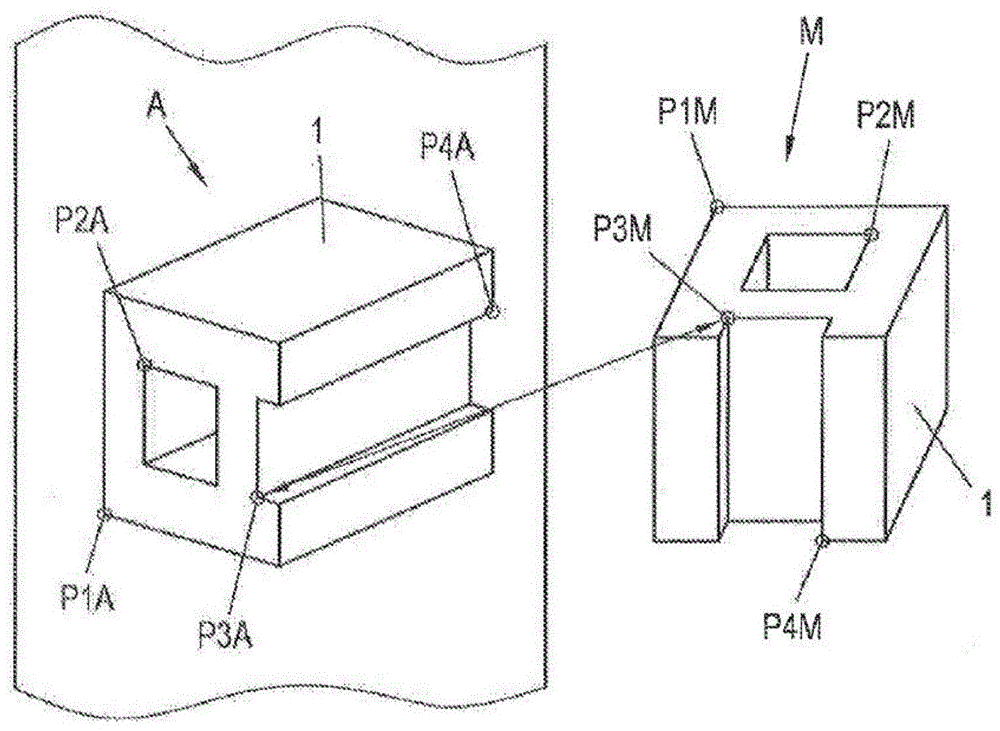
优选的,将所述实用物品的3D模型与所述二维图示的图像参数对齐的方法为:在所述二维图示和所述3D模型中分别选择多个对应点,使P1A对应P1M,P2A对应P2M,P3A对应P3M,P4A对应P4M,并且改变所述图像参数直到所述3D模型与所述二维图示对齐。Preferably, the method for aligning the 3D model of the utility item with the image parameters of the 2D illustration is as follows: selecting a plurality of corresponding points in the 2D illustration and the 3D model respectively, so that P1A corresponds to P1M , P2A corresponds to P2M, P3A corresponds to P3M, P4A corresponds to P4M, and the image parameters are changed until the 3D model is aligned with the 2D representation.
优选的,在所述二维图示中确定连续分量K1,K2,并确定连续分量K1,K2的偏心率,并且将所确定的偏心率与一预定阈值进行比较,沿纵向绘制到连续分量K1,K2的两条参考线,并且,基于从所述3D模型获得的实用物品的掩模,确定出两条参考线的哪个端点位于实用物品中。Preferably, the continuous components K1, K2 are determined in the two-dimensional diagram, and the eccentricity of the continuous components K1, K2 is determined, and the determined eccentricity is compared with a predetermined threshold, and the continuous component K1 is plotted in the longitudinal direction. , the two reference lines of K2, and, based on the mask of the utility item obtained from the 3D model, determine which endpoint of the two reference lines is located in the utility item.
优选的,使用光学字符识别软件检查注释文本的搜索区域SR被定义在两条参考线中其中一条的另一个端点周围。Preferably, the search area SR for checking the annotation text using optical character recognition software is defined around the other end point of one of the two reference lines.
优选的,位于所述实用物品内的所述参考线的端点与所述实用物品的一部分相关联。Preferably, the end points of the reference line located within the utility item are associated with a portion of the utility item.
优选的,所述二维图示包括所述实用物品的照片或CAD图,且所述二维图示的分辨率越高越好。Preferably, the two-dimensional illustration includes a photograph or a CAD drawing of the practical item, and the higher the resolution of the two-dimensional illustration, the better.
优选的,所述二维文档包括操作手册、组装说明、修理说明或培训文档中的一种或多种。Preferably, the two-dimensional document includes one or more of an operation manual, assembly instructions, repair instructions or training documents.
与现有技术相比,本发明的有益效果是:本发明提供了一种简单的用于以三维方式提供实用物品的文档的方法,可以快速、简单、使用的创建实用物品的三维文档,并且耗时较少,如果需要也可以转化为三维动画时,不需要经验丰富的3D设计师和专业的动画软件产品,因此,非常适合家用。Compared with the prior art, the beneficial effects of the present invention are: the present invention provides a simple method for providing a document of a utility item in a three-dimensional manner, which can create a three-dimensional document of a utility item in a fast, simple and usable manner, and It is less time-consuming and can be converted into 3D animation if necessary, without the need for experienced 3D designers and professional animation software products, so it is very suitable for home use.
附图说明Description of drawings
图1-图2为本发明提供的在二维文档中确定二维图示的图像参数的过程;Fig. 1-Fig. 2 is the process of determining the image parameter of two-dimensional illustration in two-dimensional document provided by the present invention;
图3-图5为本发明提供的在二维文档中用插图确定带注释的参考线的过程。Figures 3-5 illustrate the process of determining annotated reference lines with illustrations in a two-dimensional document provided by the present invention.
具体实施方式Detailed ways
下面将结合本发明实施例中的附图,对本发明实施例中的技术方面进行清楚、完整地描述,显然,所描述的实施例仅仅是本发明一部分实施例,而不是全部的实施例。基于本发明中的实施例,本领域普通技术人员在没有做出创造性劳动前提下所获得的所有其他实施例,都属于本发明保护的范围。The technical aspects of the embodiments of the present invention will be clearly and completely described below with reference to the accompanying drawings in the embodiments of the present invention. Obviously, the described embodiments are only a part of the embodiments of the present invention, but not all of the embodiments. Based on the embodiments of the present invention, all other embodiments obtained by those of ordinary skill in the art without creative efforts shall fall within the protection scope of the present invention.
请参阅图1-图5,本发明提供的一种实施例:Please refer to FIG. 1-FIG. 5, an embodiment provided by the present invention:
一种创建三维文档的方法,包括:A method of creating a three-dimensional document, comprising:
S1:提供实用物品的二维文档,并通过所述二维文档获取所述实用物品的至少一个二维图示的图像参数;S1: Provide a two-dimensional document of a practical item, and obtain image parameters of at least one two-dimensional illustration of the practical item through the two-dimensional document;
S2:将所述实用物品的3D模型与所述二维图示的图像参数对齐;S2: Align the 3D model of the utility item with the image parameters of the two-dimensional illustration;
S3:基于所述实用物品的3D模型与所述二维图示的图像参数进行比较,以确定所述实用物品的三维文档。S3: Based on the comparison of the 3D model of the utility item with the image parameters of the two-dimensional illustration, a three-dimensional document of the utility item is determined.
具体的,二维文档可以以具有二维图像的现有印刷文档的形式存在,通常以手册,操作手册,组装说明,修理说明,培训文档等的形式存在。但是,在本发明的实施例中,还可以首先重新创建用于创建三维文档的二维文档。例如,在使用根据本发明的方法之前,可以以各种视图和配置拍摄实用物品,并且照片可以用作二维图示,两种方法都被理解为本发明含义内的二维文档。本发明基于以自动方式从印刷形式(或数字化)的现有的实用物品1的二维文档创建实用物品1的三维文档。然后,也可以使用三维文档,例如,用于增强现实应用,用于基于web的训练,或用于动画文档。为此目的,分析二维文档2中的实用物品1的至少一个现有二维图示A,并且从中获得用于三维文档的信息。为此,二维图示A自然以数字形式存在于二维文档2中,例如,二维文档2中的二维图示A以足够的分辨率在两个维度上扫描,或者二维文档2已经以数字格式存在吗,选择与图中细节程度相对应的分辨率是有意义的。Specifically, the two-dimensional documentation may exist in the form of existing printed documents with two-dimensional images, usually in the form of manuals, operation manuals, assembly instructions, repair instructions, training documents, and the like. However, in an embodiment of the present invention, it is also possible to first recreate the two-dimensional document used to create the three-dimensional document. For example, utility items can be photographed in various views and configurations, and photographs can be used as two-dimensional illustrations prior to using the method according to the invention, both methods being understood as two-dimensional documents within the meaning of the present invention. The present invention is based on creating a three-dimensional document of a
本发明的先决条件是存在实用物品1的数字3D模型M,例如,数字3D模型M可以以3DCAD绘图的形式存在。由于二维文档2通常由实用物品1的制造商创建,并且现在基于或使用3D绘图的实用物品1的开发和设计是常见的,因此在大多数情况下这样的3DCAD绘图将是可用的。3DCAD绘图的优点是所有部件都包含在内并且可以识别。或者,可以对实用物品1进行3D扫描。同样,可以在三维中单独扫描实用物品1的单独部分,然后将其组合成实用物品1的3D模型。3D扫描仪和相关软件可用于此目的,允许进行这样的3D扫描。这里提到的一个例子是Kinect.RTM。来自Microsoft.RTM的传感器。结合开源软件包KinFu。A prerequisite of the present invention is the existence of a digital 3D model M of the
本发明的方法的第一步骤中,必须确定用于创建印刷文档2中的实用物品1的视图的二维图示A的特定图像参数,而不管是否二维图示A是照片或图画。两个基本图像参数是与实用物品1相关的空间观察位置,以及观察实用物品1的焦距。使用照片的示例,显然当相机相对于实用物品1的观看位置改变时,或者当照相机设置(尤其是焦距)改变时,图像改变。In the first step of the method of the invention, specific image parameters for creating a two-dimensional representation A of a view of the
在该方法的一种可能的实施方式中,用户在图像A中和在图像A中标记多个,优选地四个或更多个对应点P1A-P1M,P2A-P2M,P3A-P3M,P4A-P4M。3D模型M,如图3中所示。对应点P1A-P1M,P2A-P2M,P3A-P3M,P4A-P4M是图像A和3D模型M中的实用物品1的相同点。点P1A,P2A,P3A,P4A在实用物品1的图像A中表示。这涉及在图像A中的实用物品1的特定点P1A,P2A,P3A,P4A处标记,3D模型M中的等价点P1M,P2M,P3M,P4M,如图2所示,由点P3A,P3M之间的双箭头表示。3D模型M可以通过对应点P1A-P1M与二维图示A对齐,P2A-P2M,P3A-P3M,P4A-P4M以这样的方式使得相应的点P1A-P1M,P2A-P2M,P3A-P3M,P4A-P4M在彼此重叠时叠加。接下来,如果不知道则估计作为图像参数的焦距,这通常是这种情况。通过使用二维图示A,对应点P1A-P1M,P2A-P2M,P3A-P3M,P4A-P4M和估计的焦距,观察位置BP已经产生了实用物品的视图的二维图示A,可以通过数字图像处理中可用的,众所周知的算法,例如已知的POSIT算法来确定图1中所示的算法。通过将二维图示A和3D模型M的视图与确定的观看位置BP1叠加,例如通过在屏幕上同时显示,结果可以如图4所示进行验证。如果偏差太大(图2的左侧),则可以改变焦距和/或可以选择其他或附加的对应点。这可以迭代地重复,直到二维图示A与3D模型M的视图的足够精确的对准导致确定的观察位置BPn(图2的右侧)。观看位置BP可以由用户容易地确定,由此用户他/她自己决定何时已经实现了足够的对准。同样地,观察位置BP可以使用数字图像处理中的标准方法来确定,例如用于点识别的方法和用于确定图像对准的方法,或者以自动方式。In one possible embodiment of the method, the user marks in image A and in image A a plurality, preferably four or more corresponding points P1A-P1M, P2A-P2M, P3A-P3M, P4A- P4M. 3D model M, as shown in FIG. 3 . Corresponding points P1A-P1M, P2A-P2M, P3A-P3M, P4A-P4M are the same points of
在如所描述的那样对准印刷文档2和3D模型M中的二维二维图示A之后,可以关于上述类型的表示来分析二维图示A,基本程序是,基于二维图示与具有所确定的图像参数的3D模型的视图的比较,从二维图示获得附加信息,然后可以将其叠加在二维图像的视图上。实用文章的3D模型,以3D模型的视图的形式。为此目的,附加信息优选地与实用物品1的各个部分相关联,使得附加信息可以总是在特定视图中正确显示。After aligning the two-dimensional representation A in the printed
基于来自所确定的观看位置BP的视图中的3D模型M,创建二维掩模S(图3的右侧),其包含3D模型M的所确定视图的所有像素。使用掩模S,现在可以确定位于实用物品1的视图外部的数字化二维图示A中的所有像素(其与3D模型M的视图对齐)。通过使用数字图像处理方法,现在搜索数字化二维图示A中的连续分量。用于此目的的一种可能算法是最大稳定极值区域(MSER)算法,其表示将图像分割成连续组件的有效方法因此,以这种方式确定的每个连续分量K包括数字化二维图示A中的多个像素(由图4中的点指示)。在所有确定的连续分量K中,能够代表参考线31的那些像素,为此目的可以确定邻接部件K的偏心率。因此,偏心率被确定为连续分量K的最大纵向延伸与最大横向延伸(垂直于纵向延伸)的比率。对于参考线31,32,它可以是假设标准化为1的偏心率必须大约为1。这里可以定义适当的阈值,任何连续的组件K1。Based on the 3D model M in the view from the determined viewing position BP, a two-dimensional mask S (right side of Fig. 3) is created which contains all the pixels of the determined view of the 3D model M. Using the mask S, it is now possible to determine all the pixels in the digitized two-dimensional representation A that are outside the view of the utility item 1 (which are aligned with the view of the 3D model M). By using digital image processing methods, the continuous components in the digitized two-dimensional representation A are now searched. One possible algorithm for this purpose is the Maximum Stable Extremal Region (MSER) algorithm, which represents an efficient method of segmenting an image into continuous components. Therefore, each continuous component K determined in this way includes a digitized two-dimensional representation. A number of pixels in A (indicated by dots in Figure 4). Of all the determined continuous components K, those pixels of the reference line 31 can be represented, for which purpose the eccentricity of the adjoining part K can be determined. Therefore, the eccentricity is determined as the ratio of the maximum longitudinal extension to the maximum transverse extension (perpendicular to the longitudinal extension) of the continuous component K. For reference lines 3 1 , 3 2 , it can be assumed that the eccentricity normalized to 1 must be approximately 1. Here an appropriate threshold can be defined for any continuous component K1.
接下来,将确定参考线31,32的端点E11,E12。为此目的,可以使用任何期望的方法在纵向延伸的方向上将最佳可能的直线绘制到邻接分量K1,K2的像素中。例如,在纵向延伸方向上具有主轴H的椭圆可以围绕邻接部件K1,K2的像素安装,如图2所示。4为组件K1。然后,主轴H上的椭圆的顶点被解释为所寻找的参考线31的端点E11,E12。基于掩模S,现在可以容易地确定哪个端点E11,E12位于内部区域中,并且位于实用物品1外部的区域中。Next, the endpoints E11, E12 of the reference lines 3 1 , 3 2 will be determined. For this purpose, any desired method can be used to draw the best possible straight line in the direction of longitudinal extension into the pixels adjoining the components K1, K2. For example, an ellipse having a major axis H in the longitudinal extension direction can be fitted around the pixels of the adjoining parts K1, K2, as shown in FIG. 2 . 4 is the component K1. Then, the vertices of the ellipse on the main axis H are interpreted as the endpoints E11, E12 of the sought reference line 31 . Based on the mask S, it is now possible to easily determine which endpoints E11 , E12 are located in the inner area and in the area outside the
对于实用物品1内的终点E12,还可以基于3D模型M确定实用物品1的哪个部分确定的参考线31点。该关联还可以存储在专用部件存储器中,该专用部件存储器包含实用物品1的所有可单独识别的部件。在实用物品1内部确定的终点E12,作为参考线31的锚点AP1(图5),用于实用物品1的三维文档的指定部分的关联一起存储在部件存储器中。然而,锚点AP1也可以移动到关联部分T的相应身体中心点,这对于实用物品1的后续三维表示可能是有利的。For the end point E12 within the
搜索区域SR(现在可以在位于实用物品1外部的终点E11周围建立搜索文本或数字,例如通过传统的光学字符识别(OCR)软件。或者,注释文本也可以是以这种方式确定的注释文本同样存储在参考线31中,例如再次存储在部件存储器中。The search area SR (now can build search text or numbers around the end point E11 located outside the
如果现在在增强现实应用中改变实用物品1的视图,例如通过改变用于记录实用物品1的相机位置,则确定的参考线31和相关注释的叠加可以通过建立的锚点AP1相应地遵循文本。锚点AP1保留在实用物品1的识别部分上,并且具有注释文本的参考线31的另一个端点E11可以位于任何给定位置处的增强现实表示中,优选地位于在实用物品1的外面,如图1所示。当然,具有注释文本的参考线31可以在实用物品1的任何给定的三维视图中表示。If the view of the
尽管参照前述实施例对本发明进行了详细的说明,对于本领域的技术人员来说,其依然可以对前述各实施例所记载的技术方案进行修改,或者对其中部分技术特征进行等同替换,凡在本发明的精神和原则之内,所作的任何修改、等同替换、改进等,均应包含在本发明的保护范围之内。Although the present invention has been described in detail with reference to the foregoing embodiments, for those skilled in the art, it is still possible to modify the technical solutions described in the foregoing embodiments, or to perform equivalent replacements for some of the technical features. Any modification, equivalent replacement, improvement, etc. made within the spirit and principle of the present invention shall be included within the protection scope of the present invention.
Claims (7)
Priority Applications (1)
| Application Number | Priority Date | Filing Date | Title |
|---|---|---|---|
| CN202010654693.1A CN111833437A (en) | 2020-07-09 | 2020-07-09 | A method of creating 3D documents |
Applications Claiming Priority (1)
| Application Number | Priority Date | Filing Date | Title |
|---|---|---|---|
| CN202010654693.1A CN111833437A (en) | 2020-07-09 | 2020-07-09 | A method of creating 3D documents |
Publications (1)
| Publication Number | Publication Date |
|---|---|
| CN111833437A true CN111833437A (en) | 2020-10-27 |
Family
ID=72900862
Family Applications (1)
| Application Number | Title | Priority Date | Filing Date |
|---|---|---|---|
| CN202010654693.1A Pending CN111833437A (en) | 2020-07-09 | 2020-07-09 | A method of creating 3D documents |
Country Status (1)
| Country | Link |
|---|---|
| CN (1) | CN111833437A (en) |
Citations (2)
| Publication number | Priority date | Publication date | Assignee | Title |
|---|---|---|---|---|
| CN101918983A (en) * | 2008-01-15 | 2010-12-15 | 谷歌公司 | Three-dimensional annotations for street view data |
| US20170301134A1 (en) * | 2014-09-22 | 2017-10-19 | Avl List Gmbh | Method for creating three-dimensional documentation |
-
2020
- 2020-07-09 CN CN202010654693.1A patent/CN111833437A/en active Pending
Patent Citations (2)
| Publication number | Priority date | Publication date | Assignee | Title |
|---|---|---|---|---|
| CN101918983A (en) * | 2008-01-15 | 2010-12-15 | 谷歌公司 | Three-dimensional annotations for street view data |
| US20170301134A1 (en) * | 2014-09-22 | 2017-10-19 | Avl List Gmbh | Method for creating three-dimensional documentation |
Similar Documents
| Publication | Publication Date | Title |
|---|---|---|
| US11164001B2 (en) | Method, apparatus, and system for automatically annotating a target object in images | |
| CN107251101B (en) | Scene modification for augmented reality using markers with parameters | |
| AU2016384433B9 (en) | Generation of 3D-printed custom wearables | |
| EP2236980B1 (en) | A method for determining the relative position of a first and a second imaging device and devices therefore | |
| JP4938093B2 (en) | System and method for region classification of 2D images for 2D-TO-3D conversion | |
| CN104346834B (en) | Message processing device and position designation method | |
| US20130057642A1 (en) | Video conferencing system, method, and computer program storage device | |
| KR20210074962A (en) | Method for making video message easly and device using thereof | |
| US20240355097A1 (en) | Recognition model generation method and recognition model generation apparatus | |
| JP4834424B2 (en) | Information processing apparatus, information processing method, and program | |
| CN111833437A (en) | A method of creating 3D documents | |
| CN115222956A (en) | Multi-layer imported measurement system and its measurement method | |
| JP2021039563A (en) | Programs, devices and methods for labeling depth images as teacher data | |
| JP5618719B2 (en) | Image processing apparatus, method and program thereof | |
| KR101285111B1 (en) | Conversion device for two dimensional image to three dimensional image, and method thereof | |
| CN116152474A (en) | Scanning data processing method, device, equipment and medium | |
| JP6182930B2 (en) | Depth production support device, depth production method, and program | |
| US20170301134A1 (en) | Method for creating three-dimensional documentation | |
| JP2013217847A (en) | Imaging apparatus, length measurement method, and program | |
| CN101180657A (en) | information terminal | |
| KR20220145598A (en) | An intraoral image processing apparatus, an intraoral image processing method | |
| US20260017933A1 (en) | Building inside structure recognition system and building inside structure recognition method | |
| JP2006215986A (en) | Electronic manual creation device, electronic manual creation method and electronic manual creation program | |
| JP2007026088A (en) | Model creation apparatus | |
| JP2012014391A (en) | Comic-picture creation support apparatus, comic-picture creation support method and program |
Legal Events
| Date | Code | Title | Description |
|---|---|---|---|
| PB01 | Publication | ||
| PB01 | Publication | ||
| SE01 | Entry into force of request for substantive examination | ||
| SE01 | Entry into force of request for substantive examination | ||
| CB02 | Change of applicant information | ||
| CB02 | Change of applicant information |
Country or region after: China Address after: 570100 8g, 8th floor, Beijing Building, 56 Guomao Road, Longhua District, Haikou City, Hainan Province Applicant after: Hainan Smart Environment Investment Holding Co.,Ltd. Address before: 570100 8g, 8th floor, Beijing Building, 56 Guomao Road, Longhua District, Haikou City, Hainan Province Applicant before: Hainan development control Intelligent Environment Construction Group Co.,Ltd. Country or region before: China |
|
| RJ01 | Rejection of invention patent application after publication | ||
| RJ01 | Rejection of invention patent application after publication |
Application publication date: 20201027 |