CN111811432A - Three-dimensional imaging system and method - Google Patents
Three-dimensional imaging system and method Download PDFInfo
- Publication number
- CN111811432A CN111811432A CN202010548295.1A CN202010548295A CN111811432A CN 111811432 A CN111811432 A CN 111811432A CN 202010548295 A CN202010548295 A CN 202010548295A CN 111811432 A CN111811432 A CN 111811432A
- Authority
- CN
- China
- Prior art keywords
- projector
- camera
- dimensional
- phase
- measured
- Prior art date
- Legal status (The legal status is an assumption and is not a legal conclusion. Google has not performed a legal analysis and makes no representation as to the accuracy of the status listed.)
- Pending
Links
- 238000003384 imaging method Methods 0.000 title claims abstract description 43
- 238000000034 method Methods 0.000 title claims abstract description 31
- 230000005540 biological transmission Effects 0.000 claims abstract description 6
- 230000008569 process Effects 0.000 claims description 8
- 230000010363 phase shift Effects 0.000 claims description 6
- 238000001914 filtration Methods 0.000 claims 1
- 239000000463 material Substances 0.000 abstract description 6
- 230000004927 fusion Effects 0.000 abstract description 4
- 230000003595 spectral effect Effects 0.000 abstract description 4
- 238000000701 chemical imaging Methods 0.000 abstract description 3
- 230000003287 optical effect Effects 0.000 description 14
- 230000000694 effects Effects 0.000 description 8
- 238000005516 engineering process Methods 0.000 description 8
- 238000005259 measurement Methods 0.000 description 8
- 230000006870 function Effects 0.000 description 7
- 238000004364 calculation method Methods 0.000 description 5
- 238000010586 diagram Methods 0.000 description 5
- 238000013519 translation Methods 0.000 description 3
- 238000001514 detection method Methods 0.000 description 2
- 238000005286 illumination Methods 0.000 description 2
- 230000004048 modification Effects 0.000 description 2
- 238000012986 modification Methods 0.000 description 2
- 238000012360 testing method Methods 0.000 description 2
- 238000010521 absorption reaction Methods 0.000 description 1
- 230000003044 adaptive effect Effects 0.000 description 1
- 230000008859 change Effects 0.000 description 1
- 239000000284 extract Substances 0.000 description 1
- 230000006872 improvement Effects 0.000 description 1
- 239000003550 marker Substances 0.000 description 1
- 238000012544 monitoring process Methods 0.000 description 1
- 238000005457 optimization Methods 0.000 description 1
- 230000008447 perception Effects 0.000 description 1
- 230000005855 radiation Effects 0.000 description 1
- 230000002123 temporal effect Effects 0.000 description 1
- 230000001960 triggered effect Effects 0.000 description 1
- 239000013598 vector Substances 0.000 description 1
- 230000000007 visual effect Effects 0.000 description 1
Images


Classifications
-
- G—PHYSICS
- G01—MEASURING; TESTING
- G01B—MEASURING LENGTH, THICKNESS OR SIMILAR LINEAR DIMENSIONS; MEASURING ANGLES; MEASURING AREAS; MEASURING IRREGULARITIES OF SURFACES OR CONTOURS
- G01B11/00—Measuring arrangements characterised by the use of optical techniques
- G01B11/24—Measuring arrangements characterised by the use of optical techniques for measuring contours or curvatures
- G01B11/25—Measuring arrangements characterised by the use of optical techniques for measuring contours or curvatures by projecting a pattern, e.g. one or more lines, moiré fringes on the object
- G01B11/2504—Calibration devices
-
- G—PHYSICS
- G01—MEASURING; TESTING
- G01B—MEASURING LENGTH, THICKNESS OR SIMILAR LINEAR DIMENSIONS; MEASURING ANGLES; MEASURING AREAS; MEASURING IRREGULARITIES OF SURFACES OR CONTOURS
- G01B11/00—Measuring arrangements characterised by the use of optical techniques
- G01B11/24—Measuring arrangements characterised by the use of optical techniques for measuring contours or curvatures
- G01B11/25—Measuring arrangements characterised by the use of optical techniques for measuring contours or curvatures by projecting a pattern, e.g. one or more lines, moiré fringes on the object
- G01B11/2518—Projection by scanning of the object
- G01B11/2527—Projection by scanning of the object with phase change by in-plane movement of the patern
Landscapes
- Engineering & Computer Science (AREA)
- Computer Vision & Pattern Recognition (AREA)
- Physics & Mathematics (AREA)
- General Physics & Mathematics (AREA)
- Length Measuring Devices By Optical Means (AREA)
Abstract
本发明公开了一种三维成像系统及方法,涉及光谱成像技术领域,其中涉及到了PC机、相机、投影仪Ⅰ和投影仪Ⅱ,PC机与相机、投影仪Ⅰ和投影仪Ⅱ之间设置有触发控制通道和数据传输通道。投影仪Ⅰ与投影仪Ⅱ的投影光源波段不同;投影仪Ⅰ能投影单波段的结构光。投影仪Ⅱ能投影多种不同波段的结构光。相机位于所述投影仪Ⅰ和投影仪Ⅱ之间。相机、投影仪Ⅰ和投影仪Ⅱ均能升降调节,且它们的镜头水平朝向和上下朝向均可调节。相机、投影仪Ⅰ和投影仪Ⅱ的投影焦点汇于一点。本发明能投影多个光源波段结构光,能适用于不同材质物体的三维成像,可避免物体成像基础信息的缺失和不完整,单个系统便可实现多个光谱波段的信息采集,后期融合简单且误差较小。

The invention discloses a three-dimensional imaging system and method, and relates to the technical field of spectral imaging, in which a PC, a camera, a projector I and a projector II are involved. Trigger control channel and data transmission channel. Projector I and Projector II have different projection light source bands; Projector I can project single-band structured light. Projector II can project structured light in a variety of different wavelength bands. The camera is located between said projector I and projector II. The camera, projector I and projector II can all be adjusted up and down, and their lenses can be adjusted horizontally and vertically. The projection focal points of the camera, projector I and projector II converge at one point. The present invention can project structured light of multiple light source bands, can be applied to three-dimensional imaging of objects of different materials, can avoid the lack and incompleteness of the basic information of object imaging, a single system can realize the information collection of multiple spectral bands, and the fusion in the later stage is simple and efficient. Error is small.
Description
技术领域technical field
本发明涉及光谱成像技术领域,具体而言,涉及一种多光谱结构光三维成像系统及方法。The present invention relates to the technical field of spectral imaging, in particular to a multi-spectral structured light three-dimensional imaging system and method.
背景技术Background technique
多光谱成像技术是上世纪60年代初期出现的一种遥感技术,其波段范围及波段数的选择与应用目标直接相关,通过获得地物几个或更多波段的光谱信息,实现目标空间信息、辐射信息、光谱信息的同步获取,能够提高对目标特性的综合探测感知与识别,极大地扩展了遥感探测技术的目标分辨、监测能力。Multispectral imaging technology is a remote sensing technology that appeared in the early 1960s. The selection of the band range and the number of bands is directly related to the application target. The simultaneous acquisition of radiation information and spectral information can improve the comprehensive detection perception and identification of target characteristics, and greatly expand the target discrimination and monitoring capabilities of remote sensing detection technology.
三维成像是通过光学手段提取物体三维信息,并在重建过程中可以完整地恢复物体的三维特征的技术。如何既快又好的获取一个场景的三维信息,是三维成像技术的关键。光学三维成像技术分为被动式和主动式两大类,两者的区别在于是否通过光源进行照明.被动三维成像采用非结构照明方式,从一个或多个摄像系统获取的不同视觉方向的二维图像中,通过计算机匹配、运算来重建物体的三维面形,该种方式对没有明显特征的图像计算量很大,匹配的准确度不能保证,要想完整精确的还原物体结构,需要多个二维图像进行逆运算。基于主动三维成像,需要主动去投射结构光到被测物体上,通过结构光的变形(或者飞行时间等)来确定被测物的三维信息,由于其高效和高精度,是目前主要的三维成像技术。Three-dimensional imaging is a technology that extracts three-dimensional information of an object by optical means, and can completely restore the three-dimensional characteristics of the object during the reconstruction process. How to obtain the 3D information of a scene quickly and well is the key of 3D imaging technology. Optical 3D imaging technology is divided into two categories: passive and active. The difference between the two is whether the light source is used for illumination. Passive 3D imaging uses unstructured illumination to obtain 2D images in different visual directions from one or more camera systems. The three-dimensional surface shape of the object is reconstructed through computer matching and operation. This method requires a lot of calculation for images without obvious features, and the matching accuracy cannot be guaranteed. To completely and accurately restore the object structure, multiple two-dimensional images are required. The image is reversed. Based on active 3D imaging, it is necessary to actively project structured light onto the measured object, and determine the 3D information of the measured object through the deformation of the structured light (or time of flight, etc.). Due to its high efficiency and high precision, it is currently the main 3D imaging method. technology.
现有的主动结构光三维成像系统通常仅能投射单一光源波段结构光,存在以下问题:The existing active structured light 3D imaging system can usually only project a single light source band structured light, which has the following problems:
1)由于物体材质的差异,对不同光源波段吸收不同,单一光源会极大限制被测物体的材质。1) Due to the difference in the material of the object, the absorption of different light source bands is different, and a single light source will greatly limit the material of the object to be measured.
2)单一光源造成物体成像信息的缺失和不完整。2) A single light source causes the missing and incomplete imaging information of the object.
3)需要多个系统联合才能完成多个光谱波段的信息采集,后期融合复杂且误差较大。3) It requires the combination of multiple systems to complete the information collection of multiple spectral bands, and the later fusion is complex and the error is large.
发明内容SUMMARY OF THE INVENTION
本发明在于提供一种三维成像系统及方法,其能够缓解上述问题。The present invention is to provide a three-dimensional imaging system and method, which can alleviate the above problems.
为了缓解上述的问题,本发明采取的技术方案如下:In order to alleviate the above-mentioned problems, the technical scheme adopted by the present invention is as follows:
第一方面,本发明提供一种三维成像系统,包括PC机、相机、投影仪Ⅰ和投影仪Ⅱ,所述PC机与所述相机、投影仪Ⅰ和投影仪Ⅱ之间设置有触发控制通道和数据传输通道;In a first aspect, the present invention provides a three-dimensional imaging system, including a PC, a camera, a projector I and a projector II, and a trigger control channel is set between the PC and the camera, the projector I, and the projector II and data transmission channels;
所述投影仪Ⅰ与投影仪Ⅱ的投影光源波段不同;The projection light source bands of the projector I and the projector II are different;
所述投影仪Ⅰ能投影单波段的结构光;The projector I can project single-band structured light;
所述投影仪Ⅱ能投影多种不同波段的结构光;The projector II can project structured light in various wavelength bands;
所述相机位于所述投影仪Ⅰ和投影仪Ⅱ之间;the camera is located between the projector I and the projector II;
所述相机、投影仪Ⅰ和投影仪Ⅱ均能升降调节,且它们的镜头水平朝向和上下朝向均可调节;The camera, projector I and projector II can all be adjusted up and down, and their lenses can be adjusted horizontally and vertically;
所述相机、投影仪Ⅰ和投影仪Ⅱ的投影焦点汇于一点。The projection focal points of the camera, projector I and projector II converge at one point.
本技术方案的技术效果是:能投影多个光源波段结构光,能适用于多种不同材质的被测物体的三维成像,可避免物体成像基础信息的缺失和不完整,单个系统便可实现多个光谱波段的信息采集,后期融合简单且误差较小。The technical effects of this technical solution are: it can project multiple light source band structured lights, can be applied to the three-dimensional imaging of a variety of objects under test with different materials, can avoid the lack and incompleteness of the basic information of object imaging, and a single system can achieve multiple The information collection of each spectral band, the later fusion is simple and the error is small.
进一步地,所述相机、投影仪Ⅰ和投影仪Ⅱ分别装配于三个云台之上,它们通过云台实现升降调节,以及镜头的水平朝向和上下朝向调节,所述云台与所述PC机电连接。Further, the camera, the projector I and the projector II are respectively assembled on three gimbals, and they can be adjusted up and down through the gimbals, and the horizontal and up and down orientations of the lenses can be adjusted. Electromechanical connection.
本技术方案的技术效果是:云台作为现有成熟设备,易于获取,其能够满足相机、投影仪Ⅰ和投影仪Ⅱ的姿态及位置调节要求。The technical effect of the technical solution is that the gimbal, as an existing mature device, is easy to obtain, and can meet the posture and position adjustment requirements of the camera, projector I and projector II.
进一步地,所述相机使用6-Pin的圆形连接器作为IO接口,其中包括触发控制端口以及数据输端口。Further, the camera uses a 6-Pin circular connector as an IO interface, which includes a trigger control port and a data input port.
本技术方案的技术效果是:结构灵活,可根据设备特点或被测物体需要,动态调整成像视场范围和区域,无需重新设计结构。The technical effect of the technical solution is that the structure is flexible, and the range and area of the imaging field of view can be dynamically adjusted according to the characteristics of the equipment or the needs of the measured object, without the need to redesign the structure.
第二方面,本发明提供一种三维成像方法,采用上述的三维成像系统,该方法包括:In a second aspect, the present invention provides a three-dimensional imaging method using the above-mentioned three-dimensional imaging system, the method comprising:
S1、采用PC机生成结构光条纹,并上传至所述投影仪Ⅰ和投影仪Ⅱ;S1. Use a PC to generate structured light stripes and upload them to the projector I and projector II;
S2、在相机、投影仪Ⅰ和投影仪Ⅱ的放置有被测物体的公共视野内进行系统标定,通过PC机获取相机、投影仪Ⅰ和投影仪Ⅱ之间的相对标定参数;S2. Carry out system calibration in the public field of view of the camera, projector I and projector II where the measured object is placed, and obtain the relative calibration parameters between the camera, projector I and projector II through the PC;
S3、根据环境光线以及投影仪在被测物体上的投影光强度,调节相机的曝光亮度;S3. Adjust the exposure brightness of the camera according to the ambient light and the projected light intensity of the projector on the measured object;
S4、投影仪Ⅱ待机,投影仪Ⅰ向被测物体投影扫描单波段的结构光条纹,相机抓拍被测物体,获得一组物体变形条纹图,并上传至PC机;S4. Projector II is in standby, projector I projects and scans the single-band structured light fringes to the measured object, the camera captures the measured object, obtains a set of object deformation fringe images, and uploads them to the PC;
S5、投影仪Ⅰ待机,投影仪Ⅱ向被测物体依次投影扫描N种不同波段的结构光条纹,在此过程中,相机抓拍被测物体,获得分别与N不同种波段的结构光条纹相对应的N组物体变形条纹图,并上传至PC机;S5. The projector I is in standby, and the projector II projects and scans N structured light stripes of different wavelength bands to the measured object in turn. During this process, the camera captures the measured object and obtains structured light stripes corresponding to N different wavelength bands respectively. N groups of object deformation fringe images, and upload to PC;
S6、三维扫描,PC机根据标定参数,分别对抓拍得到的N+1组物体变形条纹图进行计算,得到N+1组物体三维扫描数据;S6, 3D scanning, the PC calculates the N+1 groups of object deformation fringe images obtained by snapping according to the calibration parameters, and obtains N+1 groups of object 3D scanning data;
S7、数据重建,根据标定参数对N+1组物体三维扫描数据进行融合得到统一坐标的三维数据,对该三维数据进行滤波,得到被测物体最终的三维点云数据,完成被测物体的三维成像。S7. Data reconstruction. According to the calibration parameters, the three-dimensional scanning data of N+1 groups of objects are fused to obtain three-dimensional data of unified coordinates, and the three-dimensional data is filtered to obtain the final three-dimensional point cloud data of the measured object, and the three-dimensional data of the measured object is completed. imaging.
本技术方案的技术效果是:通过向被测物体投影多个光源波段结构光,然后抓拍获取物体图像,能适用于多种不同材质的被测物体的三维成像,可避免物体成像基础信息的缺失和不完整,整个操作方法简单,使用非常方便;一次可完成相机、投影仪以及投影仪与相机之间的全部标定,利用标定参数可直接融合N+1组测量数据,无需特征或标记点融合,计算简单精度高。The technical effect of this technical solution is: by projecting multiple light source band structured lights onto the measured object, and then capturing the image of the object, it can be applied to the three-dimensional imaging of the measured object of various materials, and can avoid the lack of basic information of the object imaging. and incomplete, the whole operation method is simple and very convenient to use; all calibrations between the camera, the projector and the projector and the camera can be completed at one time, and the N+1 sets of measurement data can be directly fused by using the calibration parameters, without the need for feature or marker fusion. , the calculation is simple and accurate.
进一步地,所述投影仪Ⅱ能投影四种不同波段的结构光。Further, the projector II can project structured light with four different wavelength bands.
本技术方案的技术效果是:能覆盖常见的可见光投影波段。The technical effect of the technical solution is that it can cover the common visible light projection band.
更进一步地,所述投影仪Ⅰ为红外投影仪,所述投影仪Ⅱ为RGB投影仪。Further, the projector I is an infrared projector, and the projector II is an RGB projector.
本技术方案的技术效果是:可覆盖常见的被测物体材质反射波段范围。The technical effect of the technical solution is that it can cover the reflection band range of common materials of the object to be measured.
进一步地,所述步骤S1中,根据三维成像任务条件,基于时间相位和相移相位结构光算法生成所述结构光条纹。Further, in the step S1, according to the three-dimensional imaging task conditions, the structured light fringes are generated based on a time phase and a phase shift phase structured light algorithm.
进一步地,所述步骤S2中,采用九点标定法获取所述标定参数。Further, in the step S2, a nine-point calibration method is used to obtain the calibration parameters.
本技术方案的技术效果是:九点标定法利用二维平移台,可实现水平平移和360度旋转;标定板固定在二维平移台上,水平移动三个位置,在每个位置分别转动三个角度,使标定板平面与相机视场中心线分别成90°,90°-α和90°+α,其中α小于30°,从而保证标定板成像质量和标定的准确性;采集九个位置标定板图像后,利用已知标定板数据,可计算得到相机、投影仪的标定参数;标定板可采用标定点或棋盘格。The technical effects of this technical solution are: the nine-point calibration method utilizes a two-dimensional translation stage, which can realize horizontal translation and 360-degree rotation; the calibration plate is fixed on the two-dimensional translation stage, moves horizontally in three positions, and rotates three positions at each position. Make the plane of the calibration plate and the center line of the camera's field of view at 90°, 90°-α and 90°+α, where α is less than 30°, so as to ensure the imaging quality of the calibration plate and the accuracy of calibration; collect nine positions After calibrating the plate image, the calibration parameters of the camera and projector can be calculated by using the known calibration plate data; the calibration plate can use calibration points or checkerboards.
进一步地,所述步骤S3中,在调节相机的曝光亮度时,以相机能清楚的获取到被测物体的图像为准。Further, in the step S3, when adjusting the exposure brightness of the camera, the camera can clearly obtain the image of the object to be measured.
进一步地,所述步骤S6中,对于每组物体变形条纹图,首先基于时间和相移相位,获取其截断相位,再根据截断相位获取展开连续相位,最后利用标定参数和展开连续相位计算得到物体三维扫描数据。Further, in the step S6, for each group of object deformation fringe patterns, first obtain its truncated phase based on time and phase shift phase, then obtain the unwrapped continuous phase according to the truncated phase, and finally use the calibration parameters and the unwrapped continuous phase to calculate and obtain the object. 3D scan data.
本技术方案的技术效果是:适用常用的主动结构光算法,可快速有效获取高精度的完整被测物体型面。The technical effect of the technical solution is that the commonly used active structured light algorithm can be applied, and the complete surface of the measured object with high precision can be quickly and effectively obtained.
为使本发明的上述目的、特征和优点能更明显易懂,下文特举本发明实施例,并配合所附附图,作详细说明如下。In order to make the above-mentioned objects, features and advantages of the present invention more clearly understood, the following specific embodiments of the present invention are given and described in detail in conjunction with the accompanying drawings.
附图说明Description of drawings
为了更清楚地说明本发明实施例的技术方案,下面将对实施例中所需要使用的附图作简单地介绍,应当理解,以下附图仅示出了本发明的某些实施例,因此不应被看作是对范围的限定,对于本领域普通技术人员来讲,在不付出创造性劳动的前提下,还可以根据这些附图获得其他相关的附图。In order to illustrate the technical solutions of the embodiments of the present invention more clearly, the following briefly introduces the accompanying drawings used in the embodiments. It should be understood that the following drawings only show some embodiments of the present invention, and therefore do not It should be regarded as a limitation of the scope, and for those of ordinary skill in the art, other related drawings can also be obtained according to these drawings without any creative effort.
图1是本发明实施例三维成像系统的结构示意框图;1 is a schematic block diagram of the structure of a three-dimensional imaging system according to an embodiment of the present invention;
图2是本发明实施例采用九点标定法进行系统标定时的标定板位置点示意图;2 is a schematic diagram of the position point of the calibration plate when the nine-point calibration method is used for system calibration according to an embodiment of the present invention;
图3是本发明实施例相机及投影仪的布局示意图;3 is a schematic diagram of the layout of a camera and a projector according to an embodiment of the present invention;
图4是本发明实施例的触发控制示意图;4 is a schematic diagram of trigger control according to an embodiment of the present invention;
图5是本发明实施例三维成像方法的流程图;5 is a flowchart of a three-dimensional imaging method according to an embodiment of the present invention;
图6是本发明实施例差频法相位计算及展开流程图。FIG. 6 is a flow chart of phase calculation and unwrapping by the difference frequency method according to an embodiment of the present invention.
具体实施方式Detailed ways
为使本发明实施例的目的、技术方案和优点更加清楚,下面将结合本发明实施例中的附图,对本发明实施例中的技术方案进行清楚、完整地描述,显然,所描述的实施例是本发明一部分实施例,而不是全部的实施例。通常在此处附图中描述和示出的本发明实施例的组件可以以各种不同的配置来布置和设计。In order to make the purposes, technical solutions and advantages of the embodiments of the present invention clearer, the technical solutions in the embodiments of the present invention will be clearly and completely described below with reference to the accompanying drawings in the embodiments of the present invention. Obviously, the described embodiments These are some embodiments of the present invention, but not all embodiments. The components of the embodiments of the invention generally described and illustrated in the drawings herein may be arranged and designed in a variety of different configurations.
因此,以下对在附图中提供的本发明的实施例的详细描述并非旨在限制要求保护的本发明的范围,而是仅仅表示本发明的选定实施例。基于本发明中的实施例,本领域普通技术人员在没有作出创造性劳动前提下所获得的所有其他实施例,都属于本发明保护的范围。Thus, the following detailed description of the embodiments of the invention provided in the accompanying drawings is not intended to limit the scope of the invention as claimed, but is merely representative of selected embodiments of the invention. Based on the embodiments of the present invention, all other embodiments obtained by those of ordinary skill in the art without creative efforts shall fall within the protection scope of the present invention.
请参照图1,本发明实施例提供一种三维成像系统,包括PC机、相机、投影仪Ⅰ和投影仪Ⅱ,PC机与相机、投影仪Ⅰ和投影仪Ⅱ之间设置有触发控制通道和数据传输通道。Referring to FIG. 1, an embodiment of the present invention provides a three-dimensional imaging system, including a PC, a camera, a projector I and a projector II, and a trigger control channel and a data transmission channel.
其中,触发控制器用于连接于PC机与相机、投影仪Ⅰ和投影仪Ⅱ之间,用于形成触发控制通道。Among them, the trigger controller is used to connect between the PC and the camera, projector I and projector II, and is used to form a trigger control channel.
其中,投影仪Ⅰ与投影仪Ⅱ的投影光源波段不同;投影仪Ⅰ能投影单波段的结构光;投影仪Ⅱ能投影多种不同波段的结构光;相机位于投影仪Ⅰ和投影仪Ⅱ之间;相机、投影仪Ⅰ和投影仪Ⅱ均能升降调节,且它们的镜头水平朝向和上下朝向均可调节;相机、投影仪Ⅰ和投影仪Ⅱ的投影焦点汇于一点。Among them, projector I and projector II have different projection light source bands; projector I can project single-band structured light; projector II can project structured light of multiple different bands; the camera is located between projector I and projector II ; The camera, projector I and projector II can all be adjusted up and down, and their lenses can be adjusted horizontally and vertically; the projection focus of the camera, projector I and projector II converges at one point.
在本实施例中,相机、投影仪Ⅰ和投影仪Ⅱ分别装配于三个云台之上,它们通过云台实现升降调节,以及镜头的水平朝向和上下朝向调节,云台与PC机电连接,通过PC机可向云台发送姿态及位置调节信号,以调节相机、投影仪Ⅰ和投影仪Ⅱ的姿态及上下位置。In this embodiment, the camera, projector I and projector II are respectively assembled on three gimbals, and they are adjusted up and down through the gimbals, as well as the horizontal and up and down orientations of the lenses. The gimbals are electrically connected to the PC. The attitude and position adjustment signals can be sent to the PTZ through the PC to adjust the attitude and up and down positions of the camera, projector I and projector II.
在本实施例中,为了使投影仪与显示的图案同步,投影仪Ⅱ和投影仪Ⅰ都支持一组触发输入和输出,这些输入和输出通过“触发模式”部分和“触发控制”子选项卡进行配置。相机使用6-Pin圆形连接器做IO接口,包括用于形成触发控制通道的触发控制端口以及用于形成数据传输通道的数据输端口。In this embodiment, in order to synchronize the projector with the displayed pattern, both Projector II and Projector I support a set of trigger inputs and outputs, which are accessed through the "Trigger Mode" section and the "Trigger Control" sub-tab to configure. The camera uses a 6-Pin circular connector as an IO interface, including a trigger control port for forming a trigger control channel and a data input port for forming a data transmission channel.
系统在连接时,使相机的触发输入引脚与投影仪Ⅱ的触发器输出接口相连,通过在对应跳线的合适引脚的两端插入跳线来把投影仪Ⅱ的触发器输出设定至所需的逻辑电压电平,并与投影仪Ⅰ的触发器输出端口的触发输出接口相连接。When the system is connected, connect the trigger input pin of the camera to the trigger output interface of the projector II, and set the trigger output of the projector II to The required logic voltage level is connected to the trigger output interface of the trigger output port of the projector I.
在本实施例中,投影仪Ⅱ选择使用能投影四种不同波段的结构光的设备;投影仪Ⅰ为红外投影仪,投影仪Ⅱ为RGB投影仪。投影仪Ⅰ所选的型号为PDC03,用于向被测物体投影红外图像;投影仪Ⅱ所选的型号为
图3为相机及投影仪的布局示意图,其中,相机位于两投影仪中间,投影仪Ⅱ位于相机左侧,投影仪Ⅰ位于相机右侧。投影仪Ⅱ的镜头、相机镜头、投影仪Ⅰ镜头在z方向位于同一高度,相机镜头中心和投影仪Ⅱ镜头中心之间的距离为d1,相机镜头中心和投影仪Ⅰ镜头中心之间的距离也是d2,通常d1=d2。相机镜头光轴和投影仪Ⅱ镜头光轴之间的夹角为α,相机镜头光轴和投影仪Ⅰ镜头光轴之间的夹角为β,通常为了系统对称,α=β。3 is a schematic diagram of the layout of the camera and the projector, wherein the camera is located in the middle of the two projectors, the projector II is located on the left side of the camera, and the projector I is located on the right side of the camera. The lens of projector II, the camera lens, and the lens of projector I are at the same height in the z direction. The distance between the center of the camera lens and the center of the lens of projector II is d1, and the distance between the center of the camera lens and the center of the lens of projector I is also d2, usually d1=d2. The angle between the optical axis of the camera lens and the optical axis of the projector II lens is α, and the angle between the optical axis of the camera lens and the optical axis of the projector I lens is β. Usually, for system symmetry, α=β.
由于投影仪投影方向有差异,有正投影(投影方向和其镜头光轴一致)、下投影(投影方向与其镜头光轴呈夹角,即投影仪是向上一定角度投影的)和下投影(投影方向与其镜头光轴呈夹角,即投影仪是向下一定角度投影的)。因此为了保证系统的方便性,设计了云台,通过云台调节它们的姿态及位置。通过云台投影仪可以根据需要调节至任意调节角度,同时为了保证相机的成像画面范围,相机的云台可以升降,可根据需要调整相机水平高度,从而保证成像的范围合适。Due to the difference in the projection direction of the projector, there are front projection (the projection direction is consistent with the optical axis of its lens), down projection (the projection direction is at an angle with the optical axis of its lens, that is, the projector projects upward at a certain angle) and down projection (projection The direction is at an angle to the optical axis of the lens, that is, the projector projects downward at a certain angle). Therefore, in order to ensure the convenience of the system, a gimbal is designed, and their posture and position are adjusted through the gimbal. The pan-tilt projector can be adjusted to any angle as needed. At the same time, in order to ensure the imaging range of the camera, the pan-tilt of the camera can be raised and lowered, and the level of the camera can be adjusted as needed to ensure the proper imaging range.
在本实施例中,对于投影仪Ⅰ和相机,两者的光轴与投影或成像方向一致。当投影仪Ⅰ和相机水平放置时,其光轴亦在水平方向。而投影仪Ⅱ投影方向与其镜头光轴呈夹角,即投影仪Ⅱ是向上θ投影的。为了保证投影仪Ⅱ投影画面中心与相机画面中心在同一平面内且在测量距离D处相交,必须将投影仪Ⅱ机器向下θ投影,即与xoz平面的夹角为θ。In this embodiment, for the projector I and the camera, the optical axes of both are consistent with the projection or imaging direction. When the projector I and the camera are placed horizontally, their optical axis is also in the horizontal direction. The projection direction of the projector II is at an angle with the optical axis of the lens, that is, the projector II projects upward θ. In order to ensure that the center of the projected image of the projector II and the center of the camera image are in the same plane and intersect at the measurement distance D, the projector II must be projected downward by θ, that is, the angle with the xoz plane is θ.
请参照图1~图4,本发明实施例还提供了一种三维成像方法,采用上述的三维成像系统,该方法包括:Referring to FIGS. 1 to 4 , an embodiment of the present invention further provides a three-dimensional imaging method, using the above-mentioned three-dimensional imaging system, and the method includes:
1)、采用PC机生成结构光条纹,并上传至投影仪Ⅰ和投影仪Ⅱ。1) Use a PC to generate structured light stripes and upload them to Projector I and Projector II.
在本实施例中,PC机根据三维成像任务条件,基于时间相位和相移相位结构光算法实现结构光的计算,生成结构光条纹。In this embodiment, the PC implements the calculation of the structured light based on the temporal phase and the phase-shift phase structured light algorithm according to the three-dimensional imaging task conditions, and generates structured light fringes.
投影仪Ⅰ和投影仪Ⅱ通电并通过USB数据线与PC机连接,以形成数据传输通道,PC机通过该通道将生成的结构光条纹上传到投影仪中并存储。The projector I and the projector II are powered on and connected to the PC through a USB data cable to form a data transmission channel, and the PC uploads the generated structured light stripes to the projector through this channel and stores them.
2)、系统标定2), system calibration
在相机、投影仪Ⅰ和投影仪Ⅱ的放置有被测物体的公共视野内进行系统标定,通过PC机获取相机、投影仪Ⅰ和投影仪Ⅱ之间的相对标定参数。The system is calibrated in the public field of view of the camera, projector I and projector II where the measured object is placed, and the relative calibration parameters between the camera, projector I and projector II are obtained through the PC.
如图2所示,本发明实施例采用九点标定法进行系统标定,以获取标定参数。As shown in FIG. 2 , in the embodiment of the present invention, a nine-point calibration method is used for system calibration to obtain calibration parameters.
在摆放标定板时,需确保整个标定板在相机和投影仪的公共视野内,将标定板放置在该视野范围内9个不同位置并对其进行扫描。PC机通过触发控制通道向相机和投影仪发出触发控制指令,完成对标定板的扫描。When placing the calibration board, it is necessary to ensure that the entire calibration board is within the common field of view of the camera and the projector, and the calibration board is placed in 9 different positions within the field of view and scanned. The PC sends a trigger control command to the camera and the projector through the trigger control channel to complete the scanning of the calibration board.
扫描完成9个位置后,计算标定参数,标定完成,如果标定失败,重新执行标定过程。图2中c1为标定的成像最小距离,c2为标定的成像最大距离,在三维成像时,被测物体要在c1和c2之间,才能得到清晰的图像。After scanning the 9 positions, calculate the calibration parameters and complete the calibration. If the calibration fails, re-execute the calibration process. In Figure 2, c1 is the calibrated minimum imaging distance, and c2 is the calibrated maximum imaging distance. In three-dimensional imaging, the measured object must be between c1 and c2 to obtain a clear image.
3)、投影抓拍3), projection capture
首先需根据环境光线以及投影仪在被测物体上的投影光强度,调节相机的曝光亮度。Firstly, the exposure brightness of the camera needs to be adjusted according to the ambient light and the light intensity projected by the projector on the measured object.
在调节相机的曝光亮度时,以相机能清楚的获取到被测物体的图像为准,在投影仪处于视频模式下相机画面可以清楚看到被测物体,且没有太多过曝时即完成调节,否则可以调整曝光时间改变画面亮度。When adjusting the exposure brightness of the camera, the camera can clearly obtain the image of the object to be measured. When the projector is in video mode, the camera screen can clearly see the object to be measured, and the adjustment is completed when there is not too much overexposure. , otherwise you can adjust the exposure time to change the screen brightness.
在本实施例中,采用自适应曝光亮度调节,相机抓拍测试图像,计算机亮度,根据亮度分布区间,自动调节曝光亮度,使其在合适的亮度范围。In this embodiment, adaptive exposure brightness adjustment is adopted, the camera captures the test image, and the computer brightness automatically adjusts the exposure brightness according to the brightness distribution interval to make it within a suitable brightness range.
在完成相机曝光亮度调节后进行投影扫描。Projection scanning is performed after the camera exposure brightness adjustment has been completed.
首先,投影仪Ⅱ待机,投影仪Ⅰ向被测物体投影扫描红外结构光条纹,相机抓拍被测物体,获得一组物体变形条纹图,并上传至PC机;First, projector II is on standby, projector I projects and scans infrared structured light fringes on the object to be measured, and the camera captures the object to be measured, obtains a set of object deformation fringe images, and uploads them to the PC;
然后,投影仪Ⅰ待机,投影仪Ⅱ向被测物体依次投影扫描N=4种不同波段的结构光条纹,分别为红色结构光、蓝色结构光、绿色结构光和白色结构光,在此过程中,相机抓拍被测物体,获得分别与4不同种波段的结构光条纹相对应的4组物体变形条纹图,并上传至PC机。Then, the projector I is in standby, and the projector II projects and scans N=4 structured light stripes with different wavelength bands to the object to be measured in turn, namely red structured light, blue structured light, green structured light and white structured light. During this process In , the camera captures the measured object, obtains 4 groups of object deformation fringe images corresponding to the structured light fringes of 4 different wavelength bands, and uploads them to the PC.
PC机共获取到N+1=5组物体变形条纹图。A total of N+1=5 groups of object deformation fringe images were obtained by the PC.
在本实施例中,投影抓拍的触发原理如图4所示,系统工作时投影仪Ⅰ和相机构成测量系统T1,投影仪Ⅱ和相机构成测量系统T2。测量系统T1中相机处于接收触发信号的状态,投影仪Ⅰ产生的触发信号传递给相机,相机接收到触发信号后被触发拍图。测量系统T2工作过程与T1相同。在系统工作时,首先测量系统T1对被物体实施的扫描,此时投影仪Ⅱ处于等待状态,不投影任何图像。测量系统T1完成扫描后,将投影仪Ⅰ置于等待状态,关闭图像投影,再激活测量系统T2分别产生红色、蓝色、绿色和白色结构光,实施对被物体的扫描。In this embodiment, the triggering principle of projection capture is shown in FIG. 4 . When the system is working, the projector I and the camera constitute the measurement system T1, and the projector II and the camera constitute the measurement system T2. The camera in the measurement system T1 is in the state of receiving the trigger signal, the trigger signal generated by the projector I is transmitted to the camera, and the camera is triggered to take pictures after receiving the trigger signal. The working process of the measurement system T2 is the same as that of T1. When the system is working, first measure the scanning performed by the system T1 on the object, at this time the projector II is in a waiting state and does not project any image. After the measurement system T1 completes the scanning, the projector I is placed in a waiting state, the image projection is turned off, and the measurement system T2 is activated to generate red, blue, green and white structured light respectively to scan the object.
4)、三维扫描4), 3D scanning
对于每一组物体变形条纹图,PC机首先基于时间和相移相位,获取其截断相位,再根据截断相位获取展开连续相位,最后利用标定参数和展开连续相位计算得到物体三维扫描数据。For each group of object deformation fringe patterns, the PC first obtains its truncated phase based on time and phase shift phase, then obtains the unwrapped continuous phase according to the truncated phase, and finally uses the calibration parameters and the unwrapped continuous phase to calculate the three-dimensional scanning data of the object.
最终一共计算得到5组物体三维扫描数据。Finally, a total of 5 sets of 3D scanning data of objects are calculated.
在本实施例中,采用多频外差的三维扫描算法进行计算:In this embodiment, the three-dimensional scanning algorithm of multi-frequency heterodyne is used to calculate:
外差原理是运用光调制技术以及电子相位计测量经过调制的光信号的相位,将波长为λ1,λ2(λ2<λ1)的相位函数φ1和φ2经过叠加后得到新的相位函数φ,其波长为λ。则有:The principle of heterodyne is to use optical modulation technology and electronic phase meter to measure the phase of the modulated optical signal, and to superpose the phase functions φ 1 and φ 2 with wavelengths of λ 1 and λ 2 (λ 2 <λ 1 ) to obtain a new The phase function φ, whose wavelength is λ. Then there are:
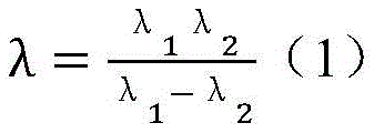
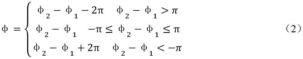
公式(1)表明可以利用高频相位函数外差后得到低频相位函数,然后利用低频相位展示和高频函数的关系实现时间相位展开。已知φ1和φ2,则外差低频相位函数可通过公式(2)计算得到。Formula (1) shows that the low-frequency phase function can be obtained by heterodyne of the high-frequency phase function, and then the time phase unwrapping can be realized by using the relationship between the low-frequency phase display and the high-frequency function. Knowing φ 1 and φ 2 , the heterodyne low-frequency phase function can be calculated by formula (2).
以三频时间相位展开为例,设投影条纹的频率分比为
最后利用标定得到的几何模型参数,从连续相位反算得到高度信息。Finally, using the geometric model parameters obtained by calibration, the height information is obtained from the continuous phase inverse calculation.
S7、数据重建S7, data reconstruction
根据标定参数对5组物体三维扫描数据进行融合得到统一坐标的三维数据,对该三维数据进行滤波,得到被测物体最终的三维点云数据,完成被测物体的三维成像。According to the calibration parameters, 5 groups of 3D scanning data of objects are fused to obtain 3D data with unified coordinates, and the 3D data is filtered to obtain the final 3D point cloud data of the measured object, and the 3D imaging of the measured object is completed.
在本实施例中,采用基于泊松方程的数据重建方法,可做到局部保形且全局最优。过程为:计算每组扫描数据的边界和法线向量,解泊松等式,使得模型指示函数梯度等于曲面法线场积分。In this embodiment, the data reconstruction method based on the Poisson equation can be used to achieve local conformality and global optimization. The process is: calculate the boundary and normal vectors of each set of scan data, and solve the Poisson equation, so that the model indicates that the gradient of the function is equal to the surface normal field integral.
以上所述仅为本发明的优选实施例而已,并不用于限制本发明,对于本领域的技术人员来说,本发明可以有各种更改和变化。凡在本发明的精神和原则之内,所作的任何修改、等同替换、改进等,均应包含在本发明的保护范围之内。The above descriptions are only preferred embodiments of the present invention, and are not intended to limit the present invention. For those skilled in the art, the present invention may have various modifications and changes. Any modification, equivalent replacement, improvement, etc. made within the spirit and principle of the present invention shall be included within the protection scope of the present invention.
Claims (10)
Priority Applications (1)
| Application Number | Priority Date | Filing Date | Title |
|---|---|---|---|
| CN202010548295.1A CN111811432A (en) | 2020-06-16 | 2020-06-16 | Three-dimensional imaging system and method |
Applications Claiming Priority (1)
| Application Number | Priority Date | Filing Date | Title |
|---|---|---|---|
| CN202010548295.1A CN111811432A (en) | 2020-06-16 | 2020-06-16 | Three-dimensional imaging system and method |
Publications (1)
| Publication Number | Publication Date |
|---|---|
| CN111811432A true CN111811432A (en) | 2020-10-23 |
Family
ID=72846258
Family Applications (1)
| Application Number | Title | Priority Date | Filing Date |
|---|---|---|---|
| CN202010548295.1A Pending CN111811432A (en) | 2020-06-16 | 2020-06-16 | Three-dimensional imaging system and method |
Country Status (1)
| Country | Link |
|---|---|
| CN (1) | CN111811432A (en) |
Cited By (3)
| Publication number | Priority date | Publication date | Assignee | Title |
|---|---|---|---|---|
| CN112361991A (en) * | 2020-11-04 | 2021-02-12 | 深圳广成创新技术有限公司 | Three-dimensional scanning method and device, computer equipment and storage medium |
| CN113532328A (en) * | 2021-07-16 | 2021-10-22 | 燕山大学 | Surface profile real-time measurement system and method in medium plate straightening process |
| CN114295076A (en) * | 2022-01-05 | 2022-04-08 | 南昌航空大学 | A measurement method to solve the shadow measurement problem of tiny objects based on structured light |
Citations (6)
| Publication number | Priority date | Publication date | Assignee | Title |
|---|---|---|---|---|
| CN102645406A (en) * | 2012-05-17 | 2012-08-22 | 天津理工大学 | Online vision detection light source based on multispectral characteristics |
| CN108475145A (en) * | 2016-01-13 | 2018-08-31 | 精工爱普生株式会社 | Pattern recognition device, image-recognizing method and image identification unit |
| CN108490000A (en) * | 2018-03-13 | 2018-09-04 | 北京科技大学 | A kind of Bar Wire Product surface defect on-line measuring device and method |
| CN110032915A (en) * | 2018-01-12 | 2019-07-19 | 杭州海康威视数字技术股份有限公司 | A kind of human face in-vivo detection method, device and electronic equipment |
| CN110312079A (en) * | 2018-03-20 | 2019-10-08 | 北京中科奥森科技有限公司 | Image collecting device and its application system |
| CN210570529U (en) * | 2019-03-05 | 2020-05-19 | 盎锐(上海)信息科技有限公司 | Calibration system for camera and projector |
-
2020
- 2020-06-16 CN CN202010548295.1A patent/CN111811432A/en active Pending
Patent Citations (6)
| Publication number | Priority date | Publication date | Assignee | Title |
|---|---|---|---|---|
| CN102645406A (en) * | 2012-05-17 | 2012-08-22 | 天津理工大学 | Online vision detection light source based on multispectral characteristics |
| CN108475145A (en) * | 2016-01-13 | 2018-08-31 | 精工爱普生株式会社 | Pattern recognition device, image-recognizing method and image identification unit |
| CN110032915A (en) * | 2018-01-12 | 2019-07-19 | 杭州海康威视数字技术股份有限公司 | A kind of human face in-vivo detection method, device and electronic equipment |
| CN108490000A (en) * | 2018-03-13 | 2018-09-04 | 北京科技大学 | A kind of Bar Wire Product surface defect on-line measuring device and method |
| CN110312079A (en) * | 2018-03-20 | 2019-10-08 | 北京中科奥森科技有限公司 | Image collecting device and its application system |
| CN210570529U (en) * | 2019-03-05 | 2020-05-19 | 盎锐(上海)信息科技有限公司 | Calibration system for camera and projector |
Cited By (4)
| Publication number | Priority date | Publication date | Assignee | Title |
|---|---|---|---|---|
| CN112361991A (en) * | 2020-11-04 | 2021-02-12 | 深圳广成创新技术有限公司 | Three-dimensional scanning method and device, computer equipment and storage medium |
| CN113532328A (en) * | 2021-07-16 | 2021-10-22 | 燕山大学 | Surface profile real-time measurement system and method in medium plate straightening process |
| CN114295076A (en) * | 2022-01-05 | 2022-04-08 | 南昌航空大学 | A measurement method to solve the shadow measurement problem of tiny objects based on structured light |
| CN114295076B (en) * | 2022-01-05 | 2023-10-20 | 南昌航空大学 | Measuring method for solving shadow measuring problem of tiny object based on structured light |
Similar Documents
| Publication | Publication Date | Title |
|---|---|---|
| US10571668B2 (en) | Catadioptric projector systems, devices, and methods | |
| CN106127745B (en) | The combined calibrating method and device of structure light 3 D vision system and line-scan digital camera | |
| CN105049829B (en) | Optical filter, imaging sensor, imaging device and 3-D imaging system | |
| US6341016B1 (en) | Method and apparatus for measuring three-dimensional shape of object | |
| CN103292699B (en) | A kind of 3 D scanning system and method | |
| CN111811432A (en) | Three-dimensional imaging system and method | |
| CN111750806A (en) | Multi-view three-dimensional measurement system and method | |
| US20140307100A1 (en) | Orthographic image capture system | |
| CN107302667A (en) | A camera interchangeable dynamic spectroscopic imaging system and its application method for high dynamic imaging | |
| CN105160680A (en) | Design method of camera with no interference depth based on structured light | |
| CN107860337B (en) | Structured light three-dimensional reconstruction method and device based on array camera | |
| CA2707176A1 (en) | Method and apparatus for rapid three-dimensional restoration | |
| KR20110084703A (en) | Board Inspection Device | |
| CN109688342A (en) | A kind of multispectral stereo imaging system | |
| CN107783353A (en) | For catching the apparatus and system of stereopsis | |
| CN206311076U (en) | Very fast 3D anthropometric scanning instrument based on speckle | |
| TW201337211A (en) | Shape reflector and surface contour mapping | |
| CN113011206A (en) | Handheld scanner and scanning method thereof | |
| US11326874B2 (en) | Structured light projection optical system for obtaining 3D data of object surface | |
| US20240087167A1 (en) | Compensation of three-dimensional measuring instrument having an autofocus camera | |
| CN111721239A (en) | Depth data measurement equipment and structured light projection device | |
| US11481917B2 (en) | Compensation of three-dimensional measuring instrument having an autofocus camera | |
| Hach et al. | A novel RGB-Z camera for high-quality motion picture applications | |
| JP2008128771A (en) | Apparatus and method for simultaneously acquiring spectroscopic information and shape information | |
| CN208536839U (en) | Image capture device |
Legal Events
| Date | Code | Title | Description |
|---|---|---|---|
| PB01 | Publication | ||
| PB01 | Publication | ||
| SE01 | Entry into force of request for substantive examination | ||
| SE01 | Entry into force of request for substantive examination |