CN111803211A - Jaw positioning system and method for maxillofacial surgery - Google Patents
Jaw positioning system and method for maxillofacial surgery Download PDFInfo
- Publication number
- CN111803211A CN111803211A CN202010667334.XA CN202010667334A CN111803211A CN 111803211 A CN111803211 A CN 111803211A CN 202010667334 A CN202010667334 A CN 202010667334A CN 111803211 A CN111803211 A CN 111803211A
- Authority
- CN
- China
- Prior art keywords
- jaw
- bone
- frame
- fork
- skull
- Prior art date
- Legal status (The legal status is an assumption and is not a legal conclusion. Google has not performed a legal analysis and makes no representation as to the accuracy of the status listed.)
- Granted
Links
Images


Classifications
-
- A—HUMAN NECESSITIES
- A61—MEDICAL OR VETERINARY SCIENCE; HYGIENE
- A61B—DIAGNOSIS; SURGERY; IDENTIFICATION
- A61B34/00—Computer-aided surgery; Manipulators or robots specially adapted for use in surgery
- A61B34/10—Computer-aided planning, simulation or modelling of surgical operations
-
- A—HUMAN NECESSITIES
- A61—MEDICAL OR VETERINARY SCIENCE; HYGIENE
- A61B—DIAGNOSIS; SURGERY; IDENTIFICATION
- A61B34/00—Computer-aided surgery; Manipulators or robots specially adapted for use in surgery
- A61B34/20—Surgical navigation systems; Devices for tracking or guiding surgical instruments, e.g. for frameless stereotaxis
-
- A—HUMAN NECESSITIES
- A61—MEDICAL OR VETERINARY SCIENCE; HYGIENE
- A61B—DIAGNOSIS; SURGERY; IDENTIFICATION
- A61B34/00—Computer-aided surgery; Manipulators or robots specially adapted for use in surgery
- A61B34/30—Surgical robots
-
- A—HUMAN NECESSITIES
- A61—MEDICAL OR VETERINARY SCIENCE; HYGIENE
- A61B—DIAGNOSIS; SURGERY; IDENTIFICATION
- A61B34/00—Computer-aided surgery; Manipulators or robots specially adapted for use in surgery
- A61B34/70—Manipulators specially adapted for use in surgery
-
- A—HUMAN NECESSITIES
- A61—MEDICAL OR VETERINARY SCIENCE; HYGIENE
- A61B—DIAGNOSIS; SURGERY; IDENTIFICATION
- A61B34/00—Computer-aided surgery; Manipulators or robots specially adapted for use in surgery
- A61B34/10—Computer-aided planning, simulation or modelling of surgical operations
- A61B2034/107—Visualisation of planned trajectories or target regions
-
- A—HUMAN NECESSITIES
- A61—MEDICAL OR VETERINARY SCIENCE; HYGIENE
- A61B—DIAGNOSIS; SURGERY; IDENTIFICATION
- A61B34/00—Computer-aided surgery; Manipulators or robots specially adapted for use in surgery
- A61B34/10—Computer-aided planning, simulation or modelling of surgical operations
- A61B2034/108—Computer aided selection or customisation of medical implants or cutting guides
-
- A—HUMAN NECESSITIES
- A61—MEDICAL OR VETERINARY SCIENCE; HYGIENE
- A61B—DIAGNOSIS; SURGERY; IDENTIFICATION
- A61B34/00—Computer-aided surgery; Manipulators or robots specially adapted for use in surgery
- A61B34/20—Surgical navigation systems; Devices for tracking or guiding surgical instruments, e.g. for frameless stereotaxis
- A61B2034/2046—Tracking techniques
- A61B2034/2051—Electromagnetic tracking systems
-
- A—HUMAN NECESSITIES
- A61—MEDICAL OR VETERINARY SCIENCE; HYGIENE
- A61B—DIAGNOSIS; SURGERY; IDENTIFICATION
- A61B34/00—Computer-aided surgery; Manipulators or robots specially adapted for use in surgery
- A61B34/20—Surgical navigation systems; Devices for tracking or guiding surgical instruments, e.g. for frameless stereotaxis
- A61B2034/2046—Tracking techniques
- A61B2034/2055—Optical tracking systems
-
- A—HUMAN NECESSITIES
- A61—MEDICAL OR VETERINARY SCIENCE; HYGIENE
- A61B—DIAGNOSIS; SURGERY; IDENTIFICATION
- A61B34/00—Computer-aided surgery; Manipulators or robots specially adapted for use in surgery
- A61B34/20—Surgical navigation systems; Devices for tracking or guiding surgical instruments, e.g. for frameless stereotaxis
- A61B2034/2046—Tracking techniques
- A61B2034/2065—Tracking using image or pattern recognition
Landscapes
- Health & Medical Sciences (AREA)
- Surgery (AREA)
- Engineering & Computer Science (AREA)
- Life Sciences & Earth Sciences (AREA)
- Biomedical Technology (AREA)
- Robotics (AREA)
- Nuclear Medicine, Radiotherapy & Molecular Imaging (AREA)
- Heart & Thoracic Surgery (AREA)
- Medical Informatics (AREA)
- Molecular Biology (AREA)
- Animal Behavior & Ethology (AREA)
- General Health & Medical Sciences (AREA)
- Public Health (AREA)
- Veterinary Medicine (AREA)
- Surgical Instruments (AREA)
Abstract
本发明公开了一种用于颌面外科手术中的颌骨定位系统及方法,该系统包括个性化颌叉、配准架、参考架、机械臂及控制模块,控制模块能够接收来自配准架、参考架等的位姿信息以及目标物体的三维数据,并控制机械臂将需要被定位的颌骨骨块定位在其目标位置。该系统的应用有利于精确实施手术,提高手术安全性和可控性,避免操作中人手及主观判断失误引入的偏差,提高手术效率。本发明公开的颌骨定位方法效果与颌骨定位系统对应。
The invention discloses a jaw bone positioning system and method used in maxillofacial surgery. The system includes a personalized jaw fork, a registration frame, a reference frame, a mechanical arm and a control module. The control module can receive data from the registration frame. , the pose information of the reference frame, etc., and the three-dimensional data of the target object, and control the robotic arm to locate the jaw bone block that needs to be positioned at its target position. The application of the system is conducive to the precise implementation of the operation, improving the safety and controllability of the operation, avoiding the deviation introduced by human hands and subjective judgment errors in the operation, and improving the operation efficiency. The effect of the jawbone positioning method disclosed in the present invention corresponds to that of the jawbone positioning system.
Description
技术领域technical field
本发明涉及口腔医疗设备领域,特别是涉及口腔医疗设备中机器人辅助手术领域,具体涉及一种口腔颌面外科正颌手术中的颌骨定位系统及方法。The invention relates to the field of oral medical equipment, in particular to the field of robot-assisted surgery in oral medical equipment, and in particular to a jaw positioning system and method in orthognathic surgery for oral and maxillofacial surgery.
背景技术Background technique
正颌手术通过将结构关系紊乱的颌骨截骨、移动并重新固定来达到治疗牙颌面畸形的目的。在移动骨块时,原有的解剖参考标志消失或难以定位,传统治疗模式是借助模型外科和医生的经验来定位,其中模型外科手段引入误差较大,治疗效果不可控程度较高。口腔颌面部骨骼形态复杂,对外观的影响重大,目前已可以通过计算机辅助设计的方法虚拟颌面外科手术过程,并通过三维打印手术导板或者影像学导航的手段来指导手术,进一步提高了手术设计的可操控性。但是使用手术导板或手术导航技术,也无法避免人手引入的误差,尤其在固定骨块时,医生手部轻微的移动就可能导致骨块固定后较明显的移位,从而影响手术效果。Orthognathic surgery treats dento-maxillofacial deformities by cutting, moving, and re-fixing the disorganized jaw. When moving the bone block, the original anatomical reference marks disappear or are difficult to locate. The traditional treatment mode relies on the experience of model surgery and doctors to locate, in which the model surgery method introduces a large error and the treatment effect is highly uncontrollable. The oral and maxillofacial bones are complex in shape, which has a significant impact on the appearance. At present, the process of maxillofacial surgery can be virtualized by the method of computer-aided design, and the operation can be guided by the means of 3D printing surgical guide or imaging navigation, which further improves the operation. Design for maneuverability. However, the use of surgical guides or surgical navigation techniques cannot avoid errors introduced by human hands. Especially when fixing bone fragments, slight movement of the doctor's hand may lead to obvious displacement of the bone fragments after fixation, thus affecting the surgical effect.
发明内容SUMMARY OF THE INVENTION
为解决现有技术中骨块定位精度不高的问题,本发明公开了一种机器人辅助的颌骨定位系统及方法,通过计算机辅助设计对手术效果进行模拟,在影像学引导下,使用机械臂将骨块准确定位到设计的位置,辅助手术医生固定骨块,如此,能够精确定位骨块位置,使术前设计得以精确体现。在固定过程中协助保持骨块位置不变可以有效降低手术误差,提高手术效率和精确性。In order to solve the problem of low positioning accuracy of bone fragments in the prior art, the present invention discloses a robot-assisted jaw positioning system and method, which simulates the surgical effect through computer-aided design, and uses a robotic arm under the guidance of imaging. The bone block is accurately positioned to the designed position, and the surgeon is assisted to fix the bone block. In this way, the position of the bone block can be accurately positioned, so that the preoperative design can be accurately reflected. Assisting in keeping the position of the bone fragments unchanged during the fixation process can effectively reduce surgical errors and improve surgical efficiency and accuracy.
为此,本发明采用的一个技术方案是:用于颌面外科手术中的颌骨定位系统,包括以下部件:To this end, a technical solution adopted in the present invention is: a jawbone positioning system used in maxillofacial surgery, comprising the following components:
可以通过其上的咬合记录限制上下颌骨位于一个唯一且可重复的位置的个性化颌叉;Individual jaw prongs that can limit the upper and lower jaws to a unique and reproducible position by the occlusal record thereon;
与个性化颌叉存在唯一且可重复拆装的固连位置的配准架;A registration frame with a unique and reusable fixed position with the personalized jaw fork;
能够刚性连接至目标物体的参考架;A reference frame capable of being rigidly attached to the target object;
以及能够接收并执行控制模块指令的机械臂,所述机械臂包含与配准架存在一固定位置关系的机械臂执行末端;and a robotic arm capable of receiving and executing instructions from the control module, wherein the robotic arm includes a robotic arm execution end that has a fixed positional relationship with the registration frame;
该颌骨定位系统包括前述控制模块;The jawbone positioning system includes the aforementioned control module;
所述控制模块能够接收来自配准架、参考架的位姿信息以及目标物体的三维数据,获得同一坐标系下配准架和参考架之间的位置关系,结合配准架与机械臂执行末端之间的位置关系,实现机械臂坐标和参考架坐标的关联,进而通过参考架的实时位置来指导机械臂动作,以将固定至机械臂的需要被定位的颌骨骨块定位在其目标位置。The control module can receive the pose information from the registration frame, the reference frame and the three-dimensional data of the target object, obtain the positional relationship between the registration frame and the reference frame in the same coordinate system, and execute the end of the registration frame and the mechanical arm. The positional relationship between the robot arm coordinates and the reference frame coordinates is realized, and the action of the robot arm is guided by the real-time position of the reference frame, so as to locate the jaw bone block that needs to be positioned fixed to the robot arm at its target position. .
此外,本发明还公开了一种用于颌面外科手术中的颌骨定位方法:其包括如下步骤:In addition, the present invention also discloses a jawbone positioning method for maxillofacial surgery, which includes the following steps:
1)采集上、下颌牙列和/或颌骨上标记物的三维数据及咬合模型;1) Collect the three-dimensional data and occlusal model of the upper and lower jaw dentition and/or markers on the jaw;
2)基于咬合位置制作颌叉,使上下颌可以通过颌叉上的咬合记录固定在唯一且可重复的位置上;2) Making jaw forks based on the occlusal position, so that the upper and lower jaws can be fixed in a unique and repeatable position through the bite recording on the jaw forks;
3)连接颌叉和配准架;3) Connect the jaw fork and the registration frame;
4)患者戴入颌叉,使上下颌牙列和/或颌骨上标记物相对于颌叉具有确定的位置,采集头颅影像;4) The patient wears the jaw fork, so that the upper and lower jaw dentition and/or the markers on the jaw have a certain position relative to the jaw fork, and the skull image is collected;
5)分割影像数据,三维重建骨骼形态;此时存在配准架相对于头颅坐标系位姿的变换矩阵M(S→F):5) Segment the image data and reconstruct the bone shape in three dimensions; at this time, there is a transformation matrix M (S→F) of the registration frame relative to the pose of the head coordinate system:
P(Facebow)=P(Skull)×M(S→F)-------①P(Facebow)=P(Skull)×M(S→F)-------①
6)分割影像中的上下颌骨数据,三维重建颌骨及牙列和/或颌骨上标记物形态,将三维扫描获取的牙列和/或颌骨上标记物数据与影像数据配准,并替换;6) Segmenting the upper and lower jaw data in the image, reconstructing the jaw and dentition and/or the shape of the markers on the jaw in 3D, and registering the dentition and/or the marker data on the jaw obtained by the 3D scanning with the image data, and replace;
7)根据手术需要进行虚拟手术设计;以确定骨块在头颅坐标系中位移的矩阵 M(MMC→MMC′),该矩阵等同于配准架相对于头颅坐标系位移的矩阵M(F→F′) 即7) Carry out virtual surgery design according to the needs of surgery; determine the matrix M (MMC→MMC′) of the displacement of the bone block in the skull coordinate system, which is equivalent to the matrix M (F→F) of the displacement of the registration frame relative to the skull coordinate system ') which is
M(MMC→MMC′)=M(F→F′)-----------②M(MMC→MMC′)=M(F→F′)------------②
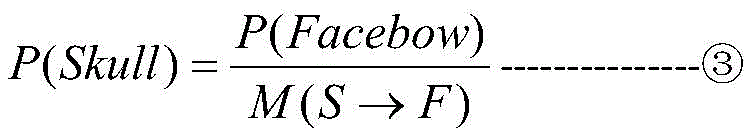
8)手术开始前,患者佩戴颌叉,平卧于手术台,所述颌叉与配准架固连,此时配准架的位姿P(Facebow)可以被捕捉,根据公式①可以计算患者头颅位姿P(Skull):8) Before the operation starts, the patient wears a jaw fork and lies on the operating table. The jaw fork is fixedly connected with the registration frame. At this time, the pose P(Facebow) of the registration frame can be captured, and the patient can be calculated according to

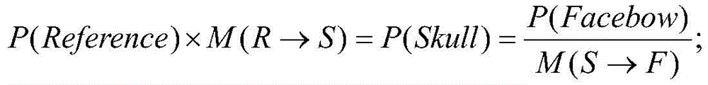
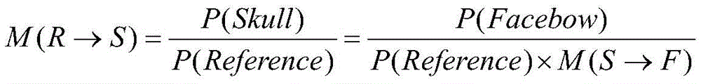
9)注册:在患者头颅上固定一个参考架,捕捉参考架的位姿P(Reference),设参考架相对于头颅坐标系的变换矩阵为M(R→S),则此时:9) Registration: Fix a reference frame on the patient's head, capture the pose P(Reference) of the reference frame, and set the transformation matrix of the reference frame relative to the head coordinate system to be M(R→S), then:
因为:because:

所以:so:
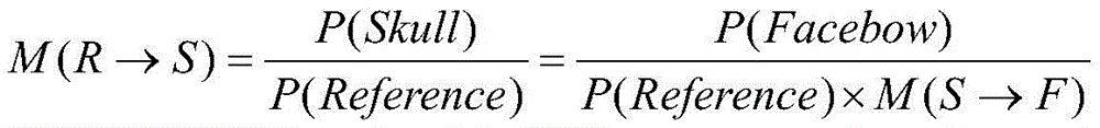
系统中即存储M(R→S)为已知值;The system stores M(R→S) as a known value;
10)解除配准架与颌叉的固连,控制模块通过参考架的位置就可以确定头颅的位姿P(Skull):10) Release the fixed connection between the registration frame and the jaw fork, and the control module can determine the pose P(Skull) of the head through the position of the reference frame:
P(Skull)=P(Reference)×M(R→S)----------------④P(Skull)=P(Reference)×M(R→S)----------------④
11)机械臂执行末端的示踪板与配准架之间存在已知的转换矩阵M(A→F),因此根据公式①11) There is a known transformation matrix M(A→F) between the tracer plate at the end of the robotic arm and the registration frame, so according to the
P(Facebow)=P(Arm)×M(A→F)=P(Skull)×M(S→F)P(Facebow)=P(Arm)×M(A→F)=P(Skull)×M(S→F)
计算机械臂位置P(Arm):Calculate the arm position P(Arm):
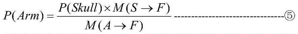
12)解除颌叉与颌骨的固连,医生实施手术,进行截骨;12) Release the fixed connection between the jaw fork and the jaw, and the doctor will perform surgery and osteotomy;
13)去除骨干扰后,基于咬合位置再次将颌叉戴入,将机械臂执行末端与颌叉固连,通过颌叉将与颌叉固连的骨块移动。13) After removing the bone interference, insert the jaw fork again based on the occlusal position, fix the execution end of the robotic arm to the jaw fork, and move the bone block fixed to the jaw fork through the jaw fork.
14)定位:根据公式②、④和⑤,基于手术计划,机械臂执行末端在术中实时头颅坐标系中将移动至位置P(Arm′):14) Positioning: According to

15)固定:术者将骨块固定于术前设计的位置上。15) Fixation: The surgeon fixes the bone block in the preoperatively designed position.
本发明的有益效果是:本发明公开的颌骨定位系统,在计算机辅助设计的基础上,通过影像获取、分析、计算及引导定位,并利用机械臂将颌骨移动并把持在准确的设计位置上,进而便于医生完成固定操作,准确实施手术设计。该系统的引入有利于精确实施手术,提高手术安全性和可控性,减少或避免操作中人手及主观判断引入的偏差,提高手术效率。本发明公开的颌骨定位方法与前述颌骨定位系统的有益效果对应,不再赘述。The beneficial effects of the present invention are as follows: the jawbone positioning system disclosed in the present invention, on the basis of computer-aided design, acquires, analyzes, calculates and guides the positioning through images, and uses the mechanical arm to move the jawbone and hold it in an accurate design position It is convenient for doctors to complete the fixation operation and accurately implement the surgical design. The introduction of the system is conducive to the precise implementation of the operation, improves the safety and controllability of the operation, reduces or avoids the deviation introduced by manpower and subjective judgment in the operation, and improves the operation efficiency. The jawbone positioning method disclosed in the present invention corresponds to the beneficial effects of the aforementioned jawbone positioning system, which will not be repeated.
附图说明Description of drawings
为了更清楚地说明本发明实施例或现有技术中的技术方案,下面将对实施例或现有技术描述中所需要使用的附图作简单地介绍,显而易见地,下面描述中的附图仅仅是本发明的某个或一些实施例,对于本领域普通技术人员来讲,在不付出创造性劳动的前提下,还可以根据这些附图获得其他的附图。In order to explain the embodiments of the present invention or the technical solutions in the prior art more clearly, the following briefly introduces the accompanying drawings that need to be used in the description of the embodiments or the prior art. Obviously, the accompanying drawings in the following description are only It is one or some embodiments of the present invention, and for those of ordinary skill in the art, other drawings can also be obtained from these drawings without creative effort.
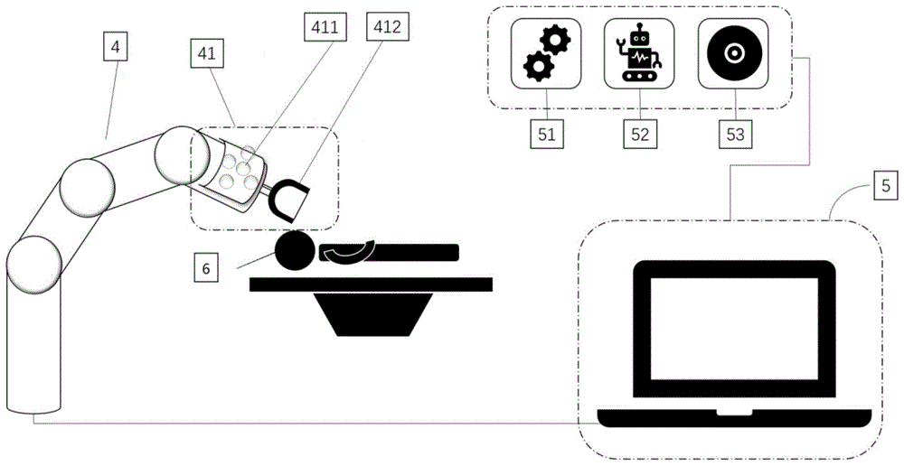
图1是本发明提供的颌面外科手术中颌骨定位系统的一个实施例的框架示意图;FIG. 1 is a schematic frame diagram of an embodiment of a jawbone positioning system in maxillofacial surgery provided by the present invention;
图2是本发明提供的颌面外科手术中颌骨定位系统的一个实施例中的颌叉的一种形式的结构示意图;2 is a schematic structural diagram of a form of a jaw fork in an embodiment of the jawbone positioning system in maxillofacial surgery provided by the present invention;
图3是本发明提供的颌面外科手术中颌骨定位系统的一个实施例中的配准架的一种形式的结构示意图;3 is a schematic structural diagram of a form of a registration frame in an embodiment of the jawbone positioning system in maxillofacial surgery provided by the present invention;
图4是本发明提供的颌面外科手术中颌骨定位系统的一个实施例中的参考架的一种形式的结构示意图。4 is a schematic structural diagram of a form of a reference frame in an embodiment of the jawbone positioning system in maxillofacial surgery provided by the present invention.
其中,附图标记:个性化颌叉1,咬合部11,末端12,配准架2,参考架3,机械臂4,机械臂执行末端41,示踪板411,把持末端412,控制模块5,手术设计模块51,影像学导航模块52,机器人控制模块53,目标物体6。Wherein, reference numerals: personalized
具体实施方式Detailed ways
下面将结合本发明实施例中的附图,对本发明实施例中的技术方案进行清楚、完整地描述,显然,所描述的实施例仅是本发明的一部分实施例,而不是全部的实施例。基于本发明中的实施例,本领域普通技术人员在没有做出创造性劳动前提下所获得的所有其他实施例,都属于本发明保护的范围。The technical solutions in the embodiments of the present invention will be clearly and completely described below with reference to the drawings in the embodiments of the present invention. Obviously, the described embodiments are only a part of the embodiments of the present invention, but not all of the embodiments. Based on the embodiments of the present invention, all other embodiments obtained by those of ordinary skill in the art without creative efforts shall fall within the protection scope of the present invention.
本发明实施例中的术语“第一”、“第二”、“第三”仅用于描述目的,而不能理解为指示或暗示相对重要性或者隐含指明所指示的技术特征的数量。由此,限定有“第一”、“第二”、“第三”的特征可以明示或者隐含地包括至少一个该特征。本发明的描述中,“多个”的含义是至少两个,例如两个,三个等,除非另有明确具体的限定。此外,术语“包括”和“具有”以及它们任何变形,意图在于覆盖不排他的包含。例如包含了一系列步骤或单元的过程、方法、系统、产品或设备没有限定于已列出的步骤或单元,而是可选地还包括没有列出的步骤或单元,或可选地还包括对于这些过程、方法、产品或设备固有的其它步骤或单元。The terms "first", "second" and "third" in the embodiments of the present invention are only used for description purposes, and cannot be understood as indicating or implying relative importance or implying the number of indicated technical features. Thus, a feature defined as "first", "second", "third" may expressly or implicitly include at least one of that feature. In the description of the present invention, "a plurality of" means at least two, such as two, three, etc., unless otherwise expressly and specifically defined. Furthermore, the terms "comprising" and "having" and any variations thereof are intended to cover non-exclusive inclusion. For example, a process, method, system, product or device comprising a series of steps or units is not limited to the listed steps or units, but optionally also includes unlisted steps or units, or optionally also includes For other steps or units inherent to these processes, methods, products or devices.
在本文中提及“实施例”意味着,结合实施例描述的特定特征、结构或特性可以包含在本发明的至少一个实施例中。在说明书中的各个位置出现该短语并不一定均是指相同的实施例,也不是与其它实施例互斥的独立的或备选的实施例。本领域技术人员显式地和隐式地理解的是,本文所描述的实施例可以与其它实施例相结合。Reference herein to an "embodiment" means that a particular feature, structure, or characteristic described in connection with the embodiment can be included in at least one embodiment of the present invention. The appearances of the phrase in various places in the specification are not necessarily all referring to the same embodiment, nor a separate or alternative embodiment that is mutually exclusive of other embodiments. It is explicitly and implicitly understood by those skilled in the art that the embodiments described herein may be combined with other embodiments.
本文中出现“位姿”一词表示位置和姿态。The term "pose" appears in this document to mean both position and pose.
参阅图1,图1是本发明提供的用于颌面外科手术中的颌骨定位系统的一个实施例的结构示意图(图1中未示出颌叉、配准架和参考架,这三者的形状构造、与其他部件的配合及其在本发明中所起的作用均有文字描述,此外,在图2、3、4中也分别给出了这三者的一种结构形式以示意)。Referring to FIG. 1, FIG. 1 is a schematic structural diagram of an embodiment of the jaw positioning system for maxillofacial surgery provided by the present invention (the jaw fork, the registration frame and the reference frame are not shown in FIG. 1, these three The shape and structure, cooperation with other components and their functions in the present invention are all described in text. In addition, in Figures 2, 3, and 4, a structural form of the three is also given for illustration) .
在一个实施例中,此定位系统包含以下部件:In one embodiment, the positioning system includes the following components:
可以通过其上的咬合记录限制上下颌骨位于一个唯一且可重复的位置的个性化颌叉1;
与个性化颌叉1存在唯一且可重复拆装的固连位置的配准架2;A
能够刚性连接至目标物体6(该目标物体需包含未被切除的人体头部骨骼,如,人体头颅)的参考架3;A
以及能够接收并执行控制模块5指令的机械臂4,所述机械臂4包含与配准架2 存在一固定位置关系的机械臂执行末端41;and a
此外,该定位系统还包括控制模块5:In addition, the positioning system also includes a control module 5:
控制模块5接收来自配准架2、参考架3的位姿信息以及目标物体6的三维数据 (例如,头颅及头颅中牙列、骨骼等数据),获得同一坐标系下配准架2和参考架3 之间的位置关系,结合配准架2和机械臂执行末端41之间的位置关系,实现机械臂坐标(一个实施例中为机械臂执行末端的示踪板)和与目标物体6固定连接的参考架3 的坐标的关联,进而通过参考架3的实时位置来指导机械臂4动作,以将固定至机械臂4的需要被定位的颌骨骨块定位在其目标位置。The
由于参考架3的坐标可以实时被检测并读取(参考架上的光学或电磁元件能够被影像学导航模块52捕捉以确定其实时位姿),手术前的机械臂执行末端41的能够与目标物体保持相对位置不变的坐标也就能够被计算,另外,在虚拟手术过程中,可以确定骨块在坐标系中的位移矩阵,由此,虚拟手术所设计的移动后的机械臂执行末端的实时坐标就能够被计算出来,进而,机械臂就能够将骨块定位在目标位置,避免术者定位引入的人为误差。Since the coordinates of the
个性化颌叉1,如图2中所示(显然,附图中给出的颌叉、配准架、参考架、示踪板等结构仅为实现本发明的一种实施方式,其并不构成对前述这些结构的形状限制,只要能够实现这些结构在本发明中需要实现的目的的结构形式,均属于本发明的保护范围),为根据咬合形态可进行个性化制作的装置,该个性化颌叉包含咬合部11 及末端12,咬合部11能够被放入上下颌之间(对于颌骨上有牙列的,咬合部11能够被放入上、下颌牙列之间,而无牙颌情况或有部分牙列但仍需在颌骨上增设人工标记物的情况下,咬合部11能够被放入上下颌骨上的人工标记物之间),在上、下颌牙列和/或颌骨上人工标记物咬入或嵌入咬合部时,末端12伸出口腔之外,该末端12能够根据需要与配准架2或机械臂执行末端41进行连接,且连接端口为同一端口。
优选的,个性化颌叉1的咬合部11包括一基准面及附于所述基准面两侧的可形成咬合记录的附着层。进一步的,所述附着层可部分被切除。Preferably, the
与个性化颌叉存在唯一的且可重复拆装的固连位置的配准架2是个刚体,如图3中所示,其上配设有光学或电磁元件,该光学或电磁元件(或者说其位置信息)具备绝对不对称结构特征,并且能够被捕捉,进而反应出配准架的位置和姿态。在一个实施例中,配准架2上的光学或电磁元件由影像学导航模块52进行捕捉。优选的,配准架2与颌叉末端12通过特定接口及螺丝进行固连。The
如图4所示,参考架3也是刚体,其上也设置有光学或电磁元件,该光学或电磁元件构成的位姿信息具备绝对不对称结构特征,能够被捕捉,进而参考架3的位置和姿态也就能够被分析出来,而参考架3通过刚性连接的方式与目标物体(如,头颅) 连接,那么该参考架3的实时位姿就能够反应目标物体的实时位姿。优选的,前述刚性连接方式为通过钛合金螺钉(螺丝)连接。As shown in FIG. 4 , the
在一个实施例中,参考架3上的光学或电磁元件被影像学导航模块52捕捉以确定其实时位姿。In one embodiment, the optical or electromagnetic elements on the
在一个实施例中,机械臂4为具备6自由度协作机械臂,其能够接收来自控制模块5的指令并执行,如图1中所示,机械臂末端为机械臂执行末端41(或者,机械臂末端固定连接机械臂执行末端41),机械臂执行末端41为一包含示踪板411及把持末端412两部分结构的刚体,示踪板411上的光和/或电磁元件(如反光球)具备绝对不对称结构特征,可通过捕捉该结构来确定机械臂执行末端41的实时位姿;把持末端412与配准架2共用颌叉1上的同一接口。In one embodiment, the
在一个实施例中,机械臂4及机械臂执行末端41的实时位姿能够被影像学导航模块52捕捉。In one embodiment, the real-time poses of the
控制模块5包含或搭载以下模块:手术设计模块51、影像学导航模块52以及机器人控制模块53。The
其中手术设计模块51能够基于影像数据对颌面部组织进行阈值分割、三维重建、二维及三维测量、截骨、平移、旋转、镜像及布尔运算等功能,实现虚拟手术过程,建立手术各步骤的模型及手术导板。The
影像学导航模块52:通过光学和/或电磁等手段捕捉固定至所需跟踪的物体(如机械臂执行末端41、骨块、颅骨、手术器械(这里的手术器械是指颌面外科手术中用到的普通的手术器械,如移除骨块时使用的截骨的手术器械,在该器械上也安装光学或电磁元件跟踪该器械的位姿将有利于提高切除操作的精确性,是本发明的一种优选实施方式))上的光学或电磁元件(如反光球)的信号,基于影像学数据,利用变换矩阵换算所需跟踪的各物体(如:机械臂执行末端、拟定位的骨块及患者头部等)位姿,通过三维可视化手段将信号对应的解剖结构、器械等实时展示在影像学数据地图上。Imaging navigation module 52: Capture and fix objects (such as robotic
具体的,影像学导航模块52通过光学和/或电磁等手段捕捉固定至患者头部的参考架3上的光或电磁元件的信号,结合患者头颅影像学数据,获得参考架3在头颅坐标系中的位置;影像学导航模块52通过光学和/或电磁等手段捕捉通过颌叉1与患者头部保持相对固定的配准架2上的光或电磁元件的信号,同样,结合患者头颅影像学数据,获得配准架2在前述坐标系中的位置;而机械臂4相对于配准架2有已知的相对位置关系,利用三者之间的位置关系(位置变换矩阵),将与患者头部刚性连接能够实时表征患者位置的且可以被捕捉位置信号的参考架3的位置和机械臂4的位置进行关联,进而,患者头部在被截骨后可以随意移动,患者的实时位置被影像学导航模块52实时捕捉,并可换算得到机械臂4的对应位置,机械臂4上固连有颌叉1,颌叉 1上固连有需要被定位的骨块,在控制模块5的控制下,机械臂4可以带动需要被定位的骨块运动至其术前设计的目标位置,而如果在虚拟手术过程中发现,需要被定位的骨块的位置相对于术前设计的位置有位移的话,该位移可以通过单独控制机械臂4 的位移来实现,此时,需要被定位的骨块就能够在机械臂4的带动下被定位在目标位置。Specifically, the
影像学导航模块52通过光学和/或电磁等手段捕捉固定至机械臂4上的光或电磁元件的信号,借此可以得到机械臂4与配准架2之间的相对位置关系(位移矩阵),此外,还可以实现对机械臂运动的闭环控制,保证机械臂将需要被定位的骨块移动至目标位置。The
进一步的,头颅坐标系可为默认坐标系,也可由患者自然头位(NHP)生成。Further, the head coordinate system may be the default coordinate system, or may be generated by the patient's natural head position (NHP).
机器人控制模块53:包含①控制软件和②外置机器人控制器(包括但不限于机器人急停按钮、脚踏和手柄):①控制软件包括但不限于:接收影像学导航模块的位姿信号、回传机械臂的实时状态、配置机械臂运动方式,微调机械臂执行末端的位姿和急停/奇点判断算法;②外置机器人控制器用于发送机械臂启动、停止、位姿变更信号和急停信号。Robot control module 53: includes ① control software and ② external robot controller (including but not limited to robot emergency stop button, foot pedal and handle): ① control software includes but is not limited to: receiving the pose signal of the imaging navigation module, Returns the real-time state of the manipulator, configures the motion mode of the manipulator, fine-tunes the pose of the manipulator execution end and the emergency stop/singularity judgment algorithm; ② The external robot controller is used to send the manipulator start, stop, pose change signals and Emergency stop signal.
控制模块5为一具备计算和通信传输性能的终端(如电脑)。实现统筹接收影像学导航模块52的定位与跟踪信息、计算各部件(包括但不限于头颅、颌骨、机械臂及手术器械等)的实时位姿并将其可视化、计算骨块移动的矩阵及目标坐标、控制机械臂运动、接受外置机器人控制器指令和安全保护指令等功能。The
如下将给出基于前述系统的用于颌面外科手术中颌骨定位的一种方法,该定位方法包括如下的步骤(在步骤前方撰写序号仅为阅读方便,部分步骤并没有必定的前后顺序关系,在实际操作中,有些步骤可以并行,或序号颠倒,因此,要根据列出的每个步骤的内容来合理判断本发明方法所包含的范围):A method for jaw positioning in maxillofacial surgery based on the aforementioned system will be given as follows, the positioning method includes the following steps (the serial numbers are written in front of the steps for ease of reading, and some steps do not have a certain sequence relationship. , in actual operation, some steps can be parallel, or the sequence number is reversed, therefore, the scope of the method of the present invention should be reasonably judged according to the content of each step listed):
1)采集上、下颌牙列和/或颌骨上标记物的三维数据及咬合模型;1) Collect the three-dimensional data and occlusal model of the upper and lower jaw dentition and/or markers on the jaw;
2)基于咬合位置制作颌叉1,使上下颌可以通过颌叉1上的咬合记录固定在唯一且可重复的位置上;2) Making
3)连接颌叉1和配准架2;3) Connect the
4)患者戴入颌叉1,使上下颌牙列和/或颌骨上标记物相对于颌叉1具有确定的位置,采集头颅影像;4) The patient wears the
进一步的,采集头颅影像所采用的影像学手段包括但不限于:螺旋CT、锥形束 CT(CBCT)、核磁(MRI);Further, the imaging methods used to collect the cranial images include but are not limited to: spiral CT, cone beam CT (CBCT), and nuclear magnetic resonance (MRI);
5)分割影像数据,三维重建骨骼形态;此时存在配准架2相对于头颅坐标系位姿的变换矩阵M(S→F):5) Segment the image data, and reconstruct the bone shape in three dimensions; at this time, there is a transformation matrix M (S→F) of the pose of the
P(Facebow)=P(Skull)×M(S→F)-------①P(Facebow)=P(Skull)×M(S→F)-------①
6)分割影像中的上下颌骨数据,三维重建颌骨及牙列和/或颌骨上标记物形态,将三维扫描获取的牙列和/或颌骨上标记物数据与影像数据配准,并替换;6) Segmenting the upper and lower jaw data in the image, reconstructing the jaw and dentition and/or the shape of the markers on the jaw in 3D, and registering the dentition and/or the marker data on the jaw obtained by the 3D scanning with the image data, and replace;
7)根据手术需要进行虚拟手术设计;以确定骨块在头颅坐标系中位移的矩阵 M(MMC→MMC′),该矩阵等同于配准架2相对于头颅坐标系位移的矩阵 M(F→F′)即7) Carry out virtual operation design according to the needs of the operation; determine the matrix M (MMC→MMC') of the displacement of the bone block in the skull coordinate system, which is equivalent to the matrix M (F→MMC') of the displacement of the
M(MMC→MMC′)=M(F→F′)-----------②M(MMC→MMC′)=M(F→F′)------------②
8)手术开始前,患者佩戴颌叉1,颌叉1与配准架2固连,患者平卧于手术台,此时影像学定位系统中可以捕捉到配准架2的位姿P(Facebow),根据公式①可以计算患者头颅位姿P(Skull):8) Before the operation begins, the patient wears the

9)注册:在患者头颅上固定一个参考架3,在影像学定位系统中捕捉到参考架3 的位姿P(Reference),设参考架3相对于头颅坐标系的变换矩阵为M(R→S),则此时:9) Registration: Fix a
因为:because:

所以:so:

系统中即存储M(R→S)为已知值;The system stores M(R→S) as a known value;
10)解除配准架2与颌叉1的固连,此时影像学定位系统中通过参考架3的位置就可以确定头颅的位姿P(Skull):10) Release the fixed connection between the
P(Skull)=P(Reference)×M(R→S)----------------④P(Skull)=P(Reference)×M(R→S)----------------④
11)机械臂执行末端41设有示踪板411和把持末端412,(示踪板411及把持末端412可以为机械臂执行末端41的一部分也可以是固定至机械臂执行末端41的部件),该把持末端412与配准架2共用颌叉1上的同一接口,示踪板411与配准架2 之间存在已知的转换矩阵M(A→F),因此根据公式①11) The robotic
P(Facebow)=P(Arm)×M(A→F)=P(Skull)×M(S→F)P(Facebow)=P(Arm)×M(A→F)=P(Skull)×M(S→F)
计算机械臂位置P(Arm):Calculate the arm position P(Arm):

12)解除颌叉1与颌骨的固连,医生实施手术,进行截骨;12) Release the fixed connection between the
13)去除骨干扰后,基于咬合位置再次将颌叉戴入,将机械臂执行末端41与颌叉 1固连,通过颌叉1将与颌叉固连的骨块移动。13) After removing the bone interference, insert the jaw fork again based on the occlusal position, fix the
14)定位:根据公式②、④和⑤,基于手术计划,机械臂执行末端41在术中实时头颅坐标系中将移动至位置P(Arm′):14) Positioning: According to

定位是根据参考架3位置实时完成,机械臂4所持骨块与头部的相对位置不随头部位姿变化而改变;The positioning is completed in real time according to the position of the
15)固定:术者将骨块固定于术前设计的位置上。15) Fixation: The surgeon fixes the bone block in the preoperatively designed position.
进一步的,在步骤1)、5)和6)中用到的三维数据是通过三维扫描或者CT数据三维重建得到的、STL、wrl、obj等CAD软件能读取和编辑的通用格式的三维数据;读取三维数据时,需要保持其坐标系不变。Further, the three-dimensional data used in steps 1), 5) and 6) is obtained by three-dimensional scanning or three-dimensional reconstruction of CT data, and can be read and edited by CAD software such as STL, wrl, obj and other three-dimensional data in a format. ; When reading 3D data, keep its coordinate system unchanged.
以上所述仅为本发明的实施例,并非因此限制本发明的专利范围,凡是利用本发明说明书及附图内容所作的等效结构或等效流程变换,或直接或间接运用在其他相关的技术领域,均同理包括在本发明的专利保护范围内。The above descriptions are only the embodiments of the present invention, and are not intended to limit the scope of the present invention. Any equivalent structure or equivalent process transformation made by using the contents of the description and drawings of the present invention, or directly or indirectly applied to other related technologies Fields are similarly included in the scope of patent protection of the present invention.
Claims (7)


Priority Applications (1)
| Application Number | Priority Date | Filing Date | Title |
|---|---|---|---|
| CN202010667334.XA CN111803211B (en) | 2020-07-13 | 2020-07-13 | Jaw positioning system and method for maxillofacial surgery |
Applications Claiming Priority (1)
| Application Number | Priority Date | Filing Date | Title |
|---|---|---|---|
| CN202010667334.XA CN111803211B (en) | 2020-07-13 | 2020-07-13 | Jaw positioning system and method for maxillofacial surgery |
Publications (2)
| Publication Number | Publication Date |
|---|---|
| CN111803211A true CN111803211A (en) | 2020-10-23 |
| CN111803211B CN111803211B (en) | 2021-11-16 |
Family
ID=72842262
Family Applications (1)
| Application Number | Title | Priority Date | Filing Date |
|---|---|---|---|
| CN202010667334.XA Active CN111803211B (en) | 2020-07-13 | 2020-07-13 | Jaw positioning system and method for maxillofacial surgery |
Country Status (1)
| Country | Link |
|---|---|
| CN (1) | CN111803211B (en) |
Cited By (7)
| Publication number | Priority date | Publication date | Assignee | Title |
|---|---|---|---|---|
| CN112546459A (en) * | 2020-12-09 | 2021-03-26 | 成都理工大学 | Tooth socket device and head tumor target area positioning method using same |
| CN113040910A (en) * | 2021-03-11 | 2021-06-29 | 南京逸动智能科技有限责任公司 | Calibration method of tracer on tail end of surgical navigation robot |
| CN113081267A (en) * | 2021-03-26 | 2021-07-09 | 北京长木谷医疗科技有限公司 | Error elimination method, error elimination device, electronic equipment and storage medium |
| CN113349927A (en) * | 2021-05-19 | 2021-09-07 | 上海交通大学 | Navigation system for face autologous fat transplantation operation and virtual scale prompting method |
| CN113952032A (en) * | 2021-12-20 | 2022-01-21 | 北京诺亦腾科技有限公司 | Space tracking equipment for orthopedic surgery |
| CN115778445A (en) * | 2022-12-07 | 2023-03-14 | 佗道医疗科技有限公司 | A verification method for laser guidance at the end of a robotic arm |
| CN116138879A (en) * | 2022-12-28 | 2023-05-23 | 上海复旦数字医疗科技股份有限公司 | Surgical robot positioning simulation method |
Citations (8)
| Publication number | Priority date | Publication date | Assignee | Title |
|---|---|---|---|---|
| CN202146362U (en) * | 2010-12-30 | 2012-02-22 | 上海交通大学医学院附属第九人民医院 | Auxiliary mechanical arm based on optical navigation and provided with seven degrees of freedom for craniomaxillofacial surgery |
| CN102551892A (en) * | 2012-01-17 | 2012-07-11 | 王旭东 | Positioning method for craniomaxillofacial surgery |
| US20180185107A1 (en) * | 2012-11-09 | 2018-07-05 | Smith & Nephew, Inc. | Systems and methods for navigation and control of an implant positioning device |
| EP3372185A1 (en) * | 2017-03-08 | 2018-09-12 | Covidien LP | System, apparatus, and method for navigating to a medical target |
| CN109481019A (en) * | 2018-09-30 | 2019-03-19 | 上海交通大学医学院附属第九人民医院 | Craniomaxillofacial surgery robot system based on optical guidance and force-feedback control |
| CN109567942A (en) * | 2018-10-31 | 2019-04-05 | 上海盼研机器人科技有限公司 | Using the craniomaxillofacial surgery robot assisted system of artificial intelligence technology |
| CN110192924A (en) * | 2019-06-20 | 2019-09-03 | 雅客智慧(北京)科技有限公司 | Positioning device and operation pathway planing method for tooth-planting operation |
| CN110831539A (en) * | 2017-04-28 | 2020-02-21 | 尼奥西斯股份有限公司 | Method and associated system for conducting guided oral and maxillofacial surgery |
-
2020
- 2020-07-13 CN CN202010667334.XA patent/CN111803211B/en active Active
Patent Citations (9)
| Publication number | Priority date | Publication date | Assignee | Title |
|---|---|---|---|---|
| CN202146362U (en) * | 2010-12-30 | 2012-02-22 | 上海交通大学医学院附属第九人民医院 | Auxiliary mechanical arm based on optical navigation and provided with seven degrees of freedom for craniomaxillofacial surgery |
| CN102551892A (en) * | 2012-01-17 | 2012-07-11 | 王旭东 | Positioning method for craniomaxillofacial surgery |
| US20180185107A1 (en) * | 2012-11-09 | 2018-07-05 | Smith & Nephew, Inc. | Systems and methods for navigation and control of an implant positioning device |
| US20180303564A1 (en) * | 2012-11-09 | 2018-10-25 | Smith & Nephew, Inc. | Systems and methods for navigation and control of an implant positioning device |
| EP3372185A1 (en) * | 2017-03-08 | 2018-09-12 | Covidien LP | System, apparatus, and method for navigating to a medical target |
| CN110831539A (en) * | 2017-04-28 | 2020-02-21 | 尼奥西斯股份有限公司 | Method and associated system for conducting guided oral and maxillofacial surgery |
| CN109481019A (en) * | 2018-09-30 | 2019-03-19 | 上海交通大学医学院附属第九人民医院 | Craniomaxillofacial surgery robot system based on optical guidance and force-feedback control |
| CN109567942A (en) * | 2018-10-31 | 2019-04-05 | 上海盼研机器人科技有限公司 | Using the craniomaxillofacial surgery robot assisted system of artificial intelligence technology |
| CN110192924A (en) * | 2019-06-20 | 2019-09-03 | 雅客智慧(北京)科技有限公司 | Positioning device and operation pathway planing method for tooth-planting operation |
Cited By (10)
| Publication number | Priority date | Publication date | Assignee | Title |
|---|---|---|---|---|
| CN112546459A (en) * | 2020-12-09 | 2021-03-26 | 成都理工大学 | Tooth socket device and head tumor target area positioning method using same |
| CN113040910A (en) * | 2021-03-11 | 2021-06-29 | 南京逸动智能科技有限责任公司 | Calibration method of tracer on tail end of surgical navigation robot |
| CN113040910B (en) * | 2021-03-11 | 2022-05-10 | 南京逸动智能科技有限责任公司 | Calibration method of tracer on tail end of surgical navigation robot |
| CN113081267A (en) * | 2021-03-26 | 2021-07-09 | 北京长木谷医疗科技有限公司 | Error elimination method, error elimination device, electronic equipment and storage medium |
| CN113081267B (en) * | 2021-03-26 | 2021-12-28 | 北京长木谷医疗科技有限公司 | Error elimination method, error elimination device, electronic equipment and storage medium |
| CN113349927A (en) * | 2021-05-19 | 2021-09-07 | 上海交通大学 | Navigation system for face autologous fat transplantation operation and virtual scale prompting method |
| CN113349927B (en) * | 2021-05-19 | 2022-11-22 | 上海交通大学 | Navigating system and virtual scale prompting method for facial autologous fat transplantation |
| CN113952032A (en) * | 2021-12-20 | 2022-01-21 | 北京诺亦腾科技有限公司 | Space tracking equipment for orthopedic surgery |
| CN115778445A (en) * | 2022-12-07 | 2023-03-14 | 佗道医疗科技有限公司 | A verification method for laser guidance at the end of a robotic arm |
| CN116138879A (en) * | 2022-12-28 | 2023-05-23 | 上海复旦数字医疗科技股份有限公司 | Surgical robot positioning simulation method |
Also Published As
| Publication number | Publication date |
|---|---|
| CN111803211B (en) | 2021-11-16 |
Similar Documents
| Publication | Publication Date | Title |
|---|---|---|
| CN111803211A (en) | Jaw positioning system and method for maxillofacial surgery | |
| CN112370163B (en) | Fibula Grafting Surgical Robot for Mandibular Reconstruction | |
| JP7282858B2 (en) | Registration of heads with individual grippers | |
| CN113633408A (en) | A dental implant robot system with optical navigation and its calibration method | |
| Chapuis et al. | A new system for computer-aided preoperative planning and intraoperative navigation during corrective jaw surgery | |
| CN101249001B (en) | Orthodontic implant anchorage three-dimensional image navigation and positioning special device | |
| Woo et al. | Autonomous bone reposition around anatomical landmark for robot-assisted orthognathic surgery | |
| CN112790885B (en) | Dental preparation system | |
| CN109925057A (en) | A kind of minimally invasive spine surgical navigation methods and systems based on augmented reality | |
| CN108210098A (en) | Man-machine cooperation robot tooth planting method based on augmented reality and man-machine cooperation robot tooth planting system | |
| CN107613896A (en) | For manipulating the method for the respective virtual object in virtual environment and associated devices and computer program product using physical object | |
| JP2020517381A (en) | Guided implementation of oral and maxillofacial treatments and related systems | |
| CN112885436B (en) | Dental surgery real-time auxiliary system based on augmented reality three-dimensional imaging | |
| CN112220557A (en) | Operation navigation and robot arm device for craniocerebral puncture and positioning method | |
| CN112972027A (en) | Orthodontic micro-implant implantation positioning method using mixed reality technology | |
| CN102335033B (en) | Individual craniofacial bone piece auxiliary positioning guide plate system and preparation method thereof | |
| CN113520603A (en) | Minimally invasive surgery robot system based on endoscope | |
| CN108553186A (en) | For the fixing device in oral cavity, tooth jaw tracker and plantation navigation system | |
| CN116737031A (en) | A tooth root information visualization system and method based on mixed reality | |
| CN108652740A (en) | A kind of scaling method of floating bone block position real-time tracking | |
| CN118177967A (en) | Craniomaxillofacial repair method, device, equipment and storage medium | |
| CN105708549A (en) | Intraoperative real-time navigation method assisting removal of foreign body in mandibular area | |
| Ghanai et al. | Computer-assisted three-dimensional surgical planning: 3D virtual articulator | |
| CN109662789B (en) | Craniomaxillofacial deformity correction robot based on 3D printed fixation plate positioning | |
| CN115429377A (en) | A surgical device for scaling and curettage of cystic lesions of the jaw |
Legal Events
| Date | Code | Title | Description |
|---|---|---|---|
| PB01 | Publication | ||
| PB01 | Publication | ||
| SE01 | Entry into force of request for substantive examination | ||
| SE01 | Entry into force of request for substantive examination | ||
| GR01 | Patent grant | ||
| GR01 | Patent grant |