CN111801495A - Fluid mixing by fluid supply lines with line-specific fluid pumps for liquid chromatography - Google Patents
Fluid mixing by fluid supply lines with line-specific fluid pumps for liquid chromatography Download PDFInfo
- Publication number
- CN111801495A CN111801495A CN201980016428.6A CN201980016428A CN111801495A CN 111801495 A CN111801495 A CN 111801495A CN 201980016428 A CN201980016428 A CN 201980016428A CN 111801495 A CN111801495 A CN 111801495A
- Authority
- CN
- China
- Prior art keywords
- fluid
- pump
- pumps
- sample
- supply lines
- Prior art date
- Legal status (The legal status is an assumption and is not a legal conclusion. Google has not performed a legal analysis and makes no representation as to the accuracy of the status listed.)
- Pending
Links
Images


Classifications
-
- F—MECHANICAL ENGINEERING; LIGHTING; HEATING; WEAPONS; BLASTING
- F04—POSITIVE - DISPLACEMENT MACHINES FOR LIQUIDS; PUMPS FOR LIQUIDS OR ELASTIC FLUIDS
- F04B—POSITIVE-DISPLACEMENT MACHINES FOR LIQUIDS; PUMPS
- F04B23/00—Pumping installations or systems
- F04B23/04—Combinations of two or more pumps
-
- G—PHYSICS
- G01—MEASURING; TESTING
- G01N—INVESTIGATING OR ANALYSING MATERIALS BY DETERMINING THEIR CHEMICAL OR PHYSICAL PROPERTIES
- G01N30/00—Investigating or analysing materials by separation into components using adsorption, absorption or similar phenomena or using ion-exchange, e.g. chromatography or field flow fractionation
- G01N30/02—Column chromatography
- G01N30/26—Conditioning of the fluid carrier; Flow patterns
- G01N30/28—Control of physical parameters of the fluid carrier
- G01N30/34—Control of physical parameters of the fluid carrier of fluid composition, e.g. gradient
-
- F—MECHANICAL ENGINEERING; LIGHTING; HEATING; WEAPONS; BLASTING
- F04—POSITIVE - DISPLACEMENT MACHINES FOR LIQUIDS; PUMPS FOR LIQUIDS OR ELASTIC FLUIDS
- F04B—POSITIVE-DISPLACEMENT MACHINES FOR LIQUIDS; PUMPS
- F04B13/00—Pumps specially modified to deliver fixed or variable measured quantities
- F04B13/02—Pumps specially modified to deliver fixed or variable measured quantities of two or more fluids at the same time
-
- B—PERFORMING OPERATIONS; TRANSPORTING
- B01—PHYSICAL OR CHEMICAL PROCESSES OR APPARATUS IN GENERAL
- B01D—SEPARATION
- B01D15/00—Separating processes involving the treatment of liquids with solid sorbents; Apparatus therefor
- B01D15/08—Selective adsorption, e.g. chromatography
- B01D15/10—Selective adsorption, e.g. chromatography characterised by constructional or operational features
- B01D15/16—Selective adsorption, e.g. chromatography characterised by constructional or operational features relating to the conditioning of the fluid carrier
-
- G—PHYSICS
- G01—MEASURING; TESTING
- G01N—INVESTIGATING OR ANALYSING MATERIALS BY DETERMINING THEIR CHEMICAL OR PHYSICAL PROPERTIES
- G01N30/00—Investigating or analysing materials by separation into components using adsorption, absorption or similar phenomena or using ion-exchange, e.g. chromatography or field flow fractionation
- G01N30/02—Column chromatography
- G01N2030/022—Column chromatography characterised by the kind of separation mechanism
- G01N2030/027—Liquid chromatography
-
- G—PHYSICS
- G01—MEASURING; TESTING
- G01N—INVESTIGATING OR ANALYSING MATERIALS BY DETERMINING THEIR CHEMICAL OR PHYSICAL PROPERTIES
- G01N30/00—Investigating or analysing materials by separation into components using adsorption, absorption or similar phenomena or using ion-exchange, e.g. chromatography or field flow fractionation
- G01N30/02—Column chromatography
- G01N30/26—Conditioning of the fluid carrier; Flow patterns
- G01N30/28—Control of physical parameters of the fluid carrier
- G01N30/34—Control of physical parameters of the fluid carrier of fluid composition, e.g. gradient
- G01N2030/347—Control of physical parameters of the fluid carrier of fluid composition, e.g. gradient mixers
-
- G—PHYSICS
- G01—MEASURING; TESTING
- G01N—INVESTIGATING OR ANALYSING MATERIALS BY DETERMINING THEIR CHEMICAL OR PHYSICAL PROPERTIES
- G01N35/00—Automatic analysis not limited to methods or materials provided for in any single one of groups G01N1/00 - G01N33/00; Handling materials therefor
- G01N35/10—Devices for transferring samples or any liquids to, in, or from, the analysis apparatus, e.g. suction devices, injection devices
- G01N35/1095—Devices for transferring samples or any liquids to, in, or from, the analysis apparatus, e.g. suction devices, injection devices for supplying the samples to flow-through analysers
- G01N35/1097—Devices for transferring samples or any liquids to, in, or from, the analysis apparatus, e.g. suction devices, injection devices for supplying the samples to flow-through analysers characterised by the valves
Landscapes
- Engineering & Computer Science (AREA)
- General Engineering & Computer Science (AREA)
- Mechanical Engineering (AREA)
- General Health & Medical Sciences (AREA)
- Analytical Chemistry (AREA)
- Biochemistry (AREA)
- Physics & Mathematics (AREA)
- General Physics & Mathematics (AREA)
- Immunology (AREA)
- Pathology (AREA)
- Chemical & Material Sciences (AREA)
- Life Sciences & Earth Sciences (AREA)
- Health & Medical Sciences (AREA)
- Treatment Of Liquids With Adsorbents In General (AREA)
- Sampling And Sample Adjustment (AREA)
Abstract
本发明涉及一种液相色谱流体供应设备(150),其用于为液相色谱样品分离设备(10)提供作为流动相的多种不同流体的混合物,其中,流体供应设备(150)包括:多个供应管线(104至107),供应管线中的每一个流体耦合到多个流体组分源(100至103)中的相应一个,以用于提供流体中的相应一种;多个流体泵(51至54),多个流体泵中的每一个与供应管线(104至107)中的相应一个相关联;和合并点(87),来自供应管线(104至107)的流体在合并点处合并,其中,多个流体泵(51至54)中的每一个根据流体供应设备(150)的相应切换状态将相应的流体从流体组分源(100至103)中的相应一个输送或不输送到合并点(87)。
The present invention relates to a liquid chromatography fluid supply device (150) for providing a mixture of multiple different fluids as a mobile phase to a liquid chromatography sample separation device (10), wherein the fluid supply device (150) comprises: a plurality of supply lines (104 to 107), each of the supply lines being fluidly coupled to a corresponding one of a plurality of fluid component sources (100 to 103) for supplying a corresponding one of the fluids; a plurality of fluid pumps (51 to 54), each of the plurality of fluid pumps being associated with a corresponding one of the supply lines (104 to 107); and a merging point (87) at which the fluids from the supply lines (104 to 107) are merged, wherein each of the plurality of fluid pumps (51 to 54) delivers or does not deliver a corresponding fluid from a corresponding one of the fluid component sources (100 to 103) to the merging point (87) according to a corresponding switching state of the fluid supply device (150).
Description
技术领域technical field
本发明涉及液相色谱流体供应设备、液相色谱样品分离设备和用于为液相色谱样品分离设备提供作为流动相的几种不同流体的混合物的方法。The present invention relates to a liquid chromatography fluid supply device, a liquid chromatography sample separation device and a method for supplying a liquid chromatography sample separation device with a mixture of several different fluids as mobile phase.
背景技术Background technique
在HPLC中,液体(流动相)通常在非常精确受控的流速(例如在每分钟微升至毫升的范围内)和在高压(通常为20至1000bar及以上,目前高达2000bar)下移动通过所谓的固定相(例如,在色谱柱中),以便将引入到流动相中的样品液体的各个馏分彼此分离,在该高压下,可以易于察觉液体的可压缩性。在通过固定相之后,在检测器中检测流体样品的分离馏分。这种HPLC系统例如从同一申请人Agilent Technologies,Inc的EP 0,309,596 B1中已知。In HPLC, a liquid (mobile phase) is usually moved through a so-called A stationary phase (eg, in a chromatographic column) in order to separate the various fractions of the sample liquid introduced into the mobile phase from each other, at this high pressure, the compressibility of the liquid can be easily detected. After passing through the stationary phase, the separated fractions of the fluid sample are detected in a detector. Such an HPLC system is known, for example, from EP 0,309,596 B1 of the same applicant, Agilent Technologies, Inc.
对于液相色谱和样品分离的其他应用,有必要进行不同流体(例如不同溶剂)的混合,其中,混合的流体组合物应当以明确的方式由这些流体形成。For other applications of liquid chromatography and sample separation, it is necessary to carry out the mixing of different fluids (eg different solvents), wherein the mixed fluid composition should be formed from these fluids in a well-defined manner.
在流体驱动装置和/或流体输送装置(特别是高压色谱泵)的上游存在多个溶剂容器,从这些容器提供溶剂(比如水和乙醇)以用于色谱分离运行(例如梯度运行)。当这些流体和/或溶剂移动通过流体管线、通过配比装置到达混合或合并点直至高压泵的点时,它们在重力的影响下加速。因此,重力作用以及尤其是流体的惯性特别地影响溶剂容器与混合点和/或高压泵的入口之间的路径。只有当所进行的流动被整合时,才能估计溶剂容器的填充水平。由于所描述的作用,流体组合物的精度取决于溶剂容器的储存高度和其填充水平。这也意味着,如果瓶相对于混合点的高度或管几何形状改变,则液相色谱设备的操作精度可能变劣。因此,溶剂容器的高度和填充水平与使用液相色谱样品分离设备的分离实验的精度相关。因此,为了使结果能够再现,使用者必须总是将溶剂布置在相同的升高位置处。这削弱了样品分离仪器操作的灵活性以及分离结果的可再现性。因此,所描述的重力作用以及流体的黏性波动和流体的惯性导致溶剂组合物的不精确性,并且因此导致样品分离的不准确性。Upstream of the fluid drive and/or fluid delivery (especially the high pressure chromatography pump) there are solvent vessels from which solvents (such as water and ethanol) are provided for chromatographic separation runs (eg gradient runs). As these fluids and/or solvents move through the fluid lines, through the proportioning device to the point of mixing or merging up to the point of the high pressure pump, they are accelerated under the influence of gravity. Thus, the effect of gravity and especially the inertia of the fluid affects in particular the path between the solvent container and the mixing point and/or the inlet of the high-pressure pump. The fill level of the solvent vessel can only be estimated when the flow being performed is integrated. Due to the described effects, the accuracy of the fluid composition depends on the storage height of the solvent container and its fill level. This also means that if the height of the bottle relative to the mixing point or the tube geometry changes, the operational accuracy of the liquid chromatography apparatus may be degraded. Therefore, the height and fill level of the solvent vessel correlates with the accuracy of separation experiments using liquid chromatography sample separation equipment. Therefore, in order to make the results reproducible, the user must always place the solvent in the same raised position. This impairs the flexibility of sample separation instrument operation and the reproducibility of separation results. Thus, the described effects of gravity, as well as the viscous fluctuations of the fluid and the inertia of the fluid, lead to inaccuracies in solvent composition and, therefore, in sample separation.
此外,已经发现,在所描述的配置中,在切换配比装置时待混合流体可能会出现体积误差。因此,在混合点或合并点处从流体管线供应的液体的精确量有时是不清楚或不准确的。还已经发现,在所描述的配置中,流体可以以不期望的方式在流体管线之间转换。所描述的寄生作用导致待混合的流体体积的丢失(或不正确)。特别地,溶剂容器与泵头之间的压力比可能是不确定的。Furthermore, it has been found that in the described configuration, volumetric errors of the fluids to be mixed may occur when switching the proportioning device. Consequently, the precise amount of liquid supplied from the fluid line at the mixing or merging point is sometimes unclear or inaccurate. It has also been found that in the described configuration, fluid can be switched between fluid lines in an undesired manner. The parasitic effects described result in a lost (or incorrect) volume of fluid to be mixed. In particular, the pressure ratio between the solvent container and the pump head may be indeterminate.
发明内容SUMMARY OF THE INVENTION
本发明的目的是在可再现的和限定的状况下生成用于液相色谱的待混合的多种流体的组合物。该目的通过独立权利要求来解决。在从属权利要求中示出了进一步的实施例。The object of the present invention is to generate, under reproducible and defined conditions, compositions of multiple fluids to be mixed for liquid chromatography. This object is solved by the independent claims. Further embodiments are shown in the dependent claims.
根据本发明的示例性执行实施例,建立了一种液相色谱流体供应设备,其用于为液相色谱样品分离设备提供作为流动相的多种不同流体的混合物,其中,该流体供应设备具有:多个供应管线,供应管线中的每一个流体耦合到多个流体组分源中的相应一个,以用于提供流体中的相应一种;多个流体泵,流体泵中的每一个与所述供应管线中的相应一个相关联;和合并点(或汇合点或结合点),来自所述供应管线的流体在合并点处合并(或汇合),其中,所述多个流体泵中的每一个根据所述流体供应设备的相应切换状态将相应的流体从所述流体组分源中的相应一个输送或不输送到所述合并点。According to an exemplary implementing embodiment of the present invention, a liquid chromatography fluid supply apparatus is established for supplying a liquid chromatography sample separation apparatus with a mixture of a plurality of different fluids as a mobile phase, wherein the fluid supply apparatus has : a plurality of supply lines, each of which is fluidly coupled to a corresponding one of a plurality of fluid component sources for supplying a corresponding one of the fluids; a plurality of fluid pumps, each of the fluid pumps being associated with all associated with a respective one of the supply lines; and a merging point (or merging or merging point) at which fluids from the supply lines merge (or merge), wherein each of the plurality of fluid pumps One delivers or does not deliver a respective fluid from a respective one of the fluid component sources to the merging point depending on the respective switching state of the fluid supply device.
根据另一示例性实施例,建立了一种用于通过液相色谱法来分离流体样品的样品分离设备,其中,所述样品分离设备包括:具有上述特征的流体供应设备,其用于提供将要在合并点处合并的流体形式的流动相,流体样品将被注射到流动相中;和样品分离装置,其配置为将注射到流动相中的流体样品分离成馏分。According to another exemplary embodiment, a sample separation device for separating fluid samples by liquid chromatography is established, wherein the sample separation device comprises: a fluid supply device having the above-mentioned characteristics for supplying the A mobile phase in fluid form combined at the combining point, into which the fluid sample will be injected; and a sample separation device configured to separate the fluid sample injected into the mobile phase into fractions.
根据又一示例性实施例,建立了一种为液相色谱样品分离设备提供作为流动相的多种不同流体的混合物(特别是通过流体供应设备,进一步特别具有上述特征)的方法,其中,该方法包括:将多个供应管线中的相应一个与多个流体组分源中的相应一个流体耦合,以用于提供流体中的相应一种;提供多个流体泵,这些流体泵中的每一个与供应管线中的相应一个相关联,以用于递送流体中的该相应一种;将来自供应管线的流体在合并点处合并;和将流体从供应管线顺序地供应到合并点,使得多个流体泵中的每一个根据相应的切换状态将相应的流体从流体组分源中的相应一个输送或不输送到合并点。According to a further exemplary embodiment, a method is established for providing a liquid chromatography sample separation device with a mixture of a plurality of different fluids as mobile phase, in particular by a fluid supply device, further in particular having the above-mentioned characteristics, wherein the The method includes: fluidly coupling a respective one of a plurality of supply lines with a respective one of a plurality of fluid component sources for providing a respective one of the fluids; providing a plurality of fluid pumps, each of the fluid pumps associated with a respective one of the supply lines for delivering the respective one of the fluids; combining the fluids from the supply lines at the merging point; and sequentially supplying the fluids from the supply lines to the merging point such that multiple Each of the fluid pumps delivers or does not deliver a corresponding fluid from a corresponding one of the fluid component sources to the merging point according to the corresponding switching state.
在本申请的语境中,术语“流体”特别地理解为是指超临界状态下的液体和/或气体和/或物质,其可选地具有固体颗粒。这种流体可以在样品分离设备的操作期间用作操作流体,其在分离过程期间由流体输送装置(例如高压泵)通过样品分离设备的流体管线来输送。这样的操作流体可以认为是流动相(即,溶剂或溶剂组合物),其可以表示样品分离过程中的载体介质和/或其可以对样品的分离过程作出功能性贡献。这意味着流动相可以携带待分离的流体样品以作为载体介质,但也可以(例如在色谱分离过程的情况下)对先前在样品分离设备处收集或由此受到阻滞的流体样品的馏分分离做出功能性贡献。In the context of the present application, the term "fluid" is understood in particular to mean a liquid and/or a gas and/or a substance in a supercritical state, which optionally has solid particles. This fluid can be used as an operating fluid during operation of the sample separation apparatus, which is delivered by a fluid delivery device (eg a high pressure pump) through the fluid lines of the sample separation apparatus during the separation process. Such operating fluids can be considered mobile phases (ie, solvents or solvent compositions), which can represent the carrier medium in the separation process of the sample and/or which can make a functional contribution to the separation process of the sample. This means that the mobile phase can carry the fluid sample to be separated as a carrier medium, but can also (for example in the case of a chromatographic separation process) separate fractions of the fluid sample previously collected at the sample separation device or blocked thereby Make functional contributions.
在本发明的语境中,术语“流体包”特别是指彼此前后地或在流体管线中顺序地流动的流体部分的时间和空间序列,这些部分在相应的流体包的物质和/或材料方面彼此不同。例如,配比装置(例如配比阀)可以可选地将携带溶剂组合物的管线耦合到不同的供应管线,其中,相应的流体包从相应的供应管线耦合到该管线中并且被输送。这导致最初稍微混合和分离的流体包的序列,然后该流体包可以彻底混合。In the context of the present invention, the term "fluidic packet" refers in particular to the temporal and spatial sequence of fluid parts flowing one behind the other or sequentially in a fluid line, these parts being in terms of substance and/or material of the respective fluidic packet different from each other. For example, a proportioning device (eg, a proportioning valve) may optionally couple the line carrying the solvent composition to a different supply line into which the respective fluid packet is coupled and delivered from the respective supply line. This results in a sequence of initially slightly mixed and separated fluidic packets, which can then be thoroughly mixed.
根据本发明的示例性实施例,建立了一种用于液相色谱的流体供应设备,其中,待混合的多种流体通过相应的供应管线并且在合并点处混合。有利的是,在将要在某一时间点供应的流体由流体泵主动地输送,该流体泵具体地与相应的供应管线相关联,使得流体由该流体泵运送到合并点,并且从该合并点例如运送到流体输送装置(比如流体高压泵)。将不在某一时间点提供的流体不能在相应的切换状态下通过与相应的其他供应管线相关联的流体泵来输送。这样,失效的流体泵在根据流体供应设备的相关联的切换或操作状态的某一时间点表示高的流体限制,其不允许或不显著地允许相应的流体通过相关联的流体泵并且可能通过布置在合并点下游的流体输送装置来输送。与此相反,输送相应流体的流体泵在相关联的启动的流体管线中形成低的流体限制,并且通过这种方式选择性地输送相关联的流体,可能地由布置在合并点下游的流体输送装置来辅助。通过这种架构,可以提供具有精确限定的流体体积的流体包,其可以在合并点混合在一起。有利的是,这样的流体供应设备尽可能地独立于充当流体组分源的溶剂贮存器的填充水平或竖直高度位置。因此,独立于对重力或质量惯性具有相应作用的流体组分源的填充水平或定位,多种流体的混合物的可再现的、快速并且精确的供应是可能的。因此,相关联的液相色谱样品分离设备可以非常精确地工作。通过这种方式,当添加用于形成溶剂组合物的溶剂时,可以避免波动的和不确定的状况,并且可以在可再现并且限定的状况下进行流体的混合。此外,通过根据本发明的示例性执行实施例的架构,可以有效地抑制和补偿溶剂组合物中不期望的压力振荡以及干扰气泡的形成。通过流体泵,流体可以达到规范化的初始压力,然后转移到下游的流体输送装置,该流体输送装置位于合并点下游,并且还可以用作定量(或计量)装置。可证明地,用作增压泵(或前级泵)的流体泵可以在流体组分源与位于合并点下游的流体输送装置之间的泵入口创建限定的压力水平。According to an exemplary embodiment of the present invention, a fluid supply apparatus for liquid chromatography is established in which a plurality of fluids to be mixed pass through respective supply lines and are mixed at a merging point. Advantageously, the fluid to be supplied at a certain point in time is actively delivered by a fluid pump, in particular associated with the respective supply line, so that the fluid is conveyed by the fluid pump to the merging point, and from the merging point For example, to a fluid delivery device (such as a fluid high pressure pump). Fluids that are not to be supplied at a certain point in time cannot be delivered by the fluid pumps associated with the respective other supply lines in the respective switching state. As such, a failed fluid pump represents a high fluid restriction at some point in time depending on the associated switching or operating state of the fluid supply device, which does not allow or insignificantly allow the corresponding fluid to pass through the associated fluid pump and possibly through the It is delivered by a fluid delivery device arranged downstream of the merging point. In contrast, the fluid pump delivering the respective fluid creates a low fluid restriction in the associated activated fluid line, and in this way selectively delivers the associated fluid, possibly by the fluid arranged downstream of the merging point device to assist. With this architecture, fluid packets with precisely defined fluid volumes can be provided that can be mixed together at the point of merging. Advantageously, such a fluid supply device is as independent as possible from the fill level or vertical height position of the solvent reservoir serving as the source of the fluid components. Thus, a reproducible, fast and precise supply of mixtures of multiple fluids is possible independently of the fill level or positioning of the source of fluid components with corresponding effects on gravity or mass inertia. Therefore, the associated liquid chromatography sample separation device can work very precisely. In this way, fluctuating and indeterminate conditions can be avoided when adding the solvent used to form the solvent composition, and mixing of fluids can be performed under reproducible and defined conditions. Furthermore, by the architecture according to the exemplary implementing embodiments of the present invention, undesired pressure oscillations in the solvent composition and the formation of interfering bubbles can be effectively suppressed and compensated. With a fluid pump, the fluid can be brought to a normalized initial pressure and then transferred to a downstream fluid delivery device, which is located downstream of the merging point and can also be used as a dosing (or metering) device. Arguably, a fluid pump used as a booster pump (or backing pump) can create a defined pressure level at the pump inlet between the source of the fluid components and the fluid delivery device located downstream of the merging point.
下面描述流体供应设备、方法和样品分离设备的附加实施方式。Additional embodiments of fluid supply devices, methods, and sample separation devices are described below.
根据实施例,流体泵中的每一个可以仅恰好单独地与供应管线中的相应一个相关联。此外,供应管线中的每一个可以仅恰好单独地与流体泵中的一个相关联。与此相反,以下更详细地描述的流体输送装置可以共同地分配给所有供应管线。According to an embodiment, each of the fluid pumps may only be associated with a respective one of the supply lines individually. Furthermore, each of the supply lines may be individually associated with only exactly one of the fluid pumps. In contrast, the fluid delivery devices described in more detail below can be assigned to all supply lines in common.
根据实施例,多个流体泵中的每一个可以呈现为能够进行切换(特别是能够开启或关断)(例如,由控制装置控制),使得根据其相应的切换状态(其然后可以对应于流体供应设备的上述切换状态),相应的流体泵将相应的流体从相应的流体组分源输送(即当相应的流体泵开启时)或不输送(即当相应的流体泵关断时)到合并点。如果流体泵中的相应一个开启,则相关联的流体被递送通过相关联的流体管线。另一方面,如果流体泵中的一个被关断,则这会导致如此高的流体阻力(甚至相对于当前生效的流体泵),使得即使流体递送装置也不能通过相关联的流体管线输送显著量的相关联的流体。优选地,除了一个流体泵之外的所有流体泵可以在某一时间点关断,从而限定了正好在该时间点递送的流体。在某一时间点唯一生效或开启的流体泵或增压泵由于其运行而具有到目前为止所有流体供应通道中的最低流体阻力。由于关断的流体泵的高流体阻力,并且还由于上述生效和失效的流体馈送泵的大阻力差,潜在的泄漏是可以忽略的。According to an embodiment, each of the plurality of fluid pumps may be rendered switchable (in particular able to be switched on or off) (eg controlled by a control device) such that according to its respective switching state (which may then correspond to the fluid the aforementioned switching states of the supply device), the respective fluid pump delivers the respective fluid from the respective source of the fluid components (ie when the respective fluid pump is on) or not (ie when the respective fluid pump is off) to the merge point. If the respective one of the fluid pumps is turned on, the associated fluid is delivered through the associated fluid line. On the other hand, if one of the fluid pumps is switched off, this can result in such a high fluid resistance (even relative to the currently active fluid pump) that even the fluid delivery device cannot deliver a significant amount through the associated fluid line the associated fluid. Preferably, all but one of the fluid pumps can be switched off at a certain point in time, thereby defining the fluid delivered at exactly that point in time. The only active or switched on fluid pump or booster pump at a certain point in time has by far the lowest fluid resistance of all fluid supply channels due to its operation. Potential leakage is negligible due to the high fluid resistance of the shut-off fluid pump, and also due to the large resistance difference of the active and inactive fluid feed pumps described above.
替代地或附加地,流体供应设备可以具有至少一个切换阀(优选地呈现为流体阀)(特别是每个流体管线一个相应的切换阀),其中,多个流体泵中的每一个在操作期间连续运行,使得根据至少一个切换阀的相应切换状态(其于是对应于流体供应设备的上述切换状态),相应的流体泵将相应的流体从流体组分源中相应一个输送(即当相应的流体泵开启并且相关联的切换阀打开时)或者不输送(即当相应的流体泵开启或者关断并且相关联的切换阀关闭时)到合并点。根据该实施例,流体管线中的所有流体泵也可以连续地维持开启,其中,(优选地精确地)相应打开状态下的一个切换阀限定当前是哪种流体从哪个流体管线输送到合并点。Alternatively or additionally, the fluid supply device may have at least one switching valve (preferably represented as a fluid valve) (in particular one corresponding switching valve per fluid line), wherein each of the plurality of fluid pumps during operation Continuous operation, so that depending on the respective switching state of the at least one switching valve (which then corresponds to the aforementioned switching state of the fluid supply device), the respective fluid pump delivers the respective fluid from the respective one of the fluid component sources (ie when the respective fluid When the pump is on and the associated switching valve is open) or not delivering (ie when the corresponding fluid pump is on or off and the associated switching valve is closed) to the merging point. According to this embodiment, all fluid pumps in the fluid lines can also be kept open continuously, wherein (preferably precisely) a switching valve in the respective open state defines which fluid is currently being fed from which fluid line to the merging point.
根据实施例,在多个流体泵与至少一个切换阀之间可以布置有至少一个流体容积,以作为流体贮存器或压力贮存器。在该实施例中,从流体泵到可选的配比阀的连接因此也可以有意地设置有一个或多个流体容积,其增加了定量单元的最大可实现流速并且使流动平稳。因此,也增加了流体组合物的最大生产速度。According to an embodiment, at least one fluid volume may be arranged between the plurality of fluid pumps and the at least one switching valve as a fluid reservoir or a pressure reservoir. In this embodiment, the connection from the fluid pump to the optional proportioning valve can thus also be intentionally provided with one or more fluid volumes which increase the maximum achievable flow rate of the dosing unit and smooth the flow. Thus, the maximum production rate of the fluid composition is also increased.
根据实施例,成分待混合的流体可以是流动相,待分离的流体样品将在(特别是色谱)样品分离期间引入该流动相。这种流动相特别地可以是溶剂或者恒定或可变的溶剂组合物,其沿着样品分离设备的流体管线携带待分离的流体样品。在色谱分离实验中,例如,在将流体样品的馏分吸附到样品分离设备的固定相上之后的梯度操作中,通过相继改变流动相的溶剂组合物,流动相可以以分馏的方式将馏分从样品分离设备(比如色谱分离柱)中分离。替代地,例如,溶剂组合物可以随时间维持恒定的等度模式也是可能的。流动相的精确组合物对流速和/或输送的流体体积量具有影响。这种影响转而影响分离结果的精度,特别是色谱图中峰的位置和幅值(特别是高度)。通过增加组合物的精度和流动相的生产率,可以获得更多可比较的分离数据,并且分离结果(例如色谱分离方法中的色谱图)可以变得更精确。According to an embodiment, the fluid in which the components are to be mixed may be a mobile phase into which the fluid sample to be separated is to be introduced during (in particular chromatographic) sample separation. This mobile phase may in particular be a solvent or a constant or variable solvent composition which carries the fluid sample to be separated along the fluid line of the sample separation device. In chromatographic separation experiments, for example, in gradient operations following adsorption of fractions of a fluid sample onto the stationary phase of a sample separation device, by sequentially changing the solvent composition of the mobile phase, the mobile phase can fractionally separate the fractions from the sample from the sample. separation equipment (such as a chromatographic separation column). Alternatively, for example, it is also possible that the solvent composition may maintain a constant isocratic pattern over time. The precise composition of the mobile phase has an effect on the flow rate and/or the amount of fluid volume delivered. This effect in turn affects the accuracy of the separation results, especially the position and amplitude (especially height) of the peaks in the chromatogram. By increasing the precision of the composition and the productivity of the mobile phase, more comparable separation data can be obtained, and separation results (eg, chromatograms in chromatographic separation methods) can become more precise.
根据本发明的实施例,流体供应设备可以(除了流体泵之外)具有流体输送装置,流体输送装置位于合并点下游并且配置为在液相色谱样品分离设备中输送作为流动相的流体。特别地,在所有通道上延伸和/或为所有供应管线共同设置的流体输送装置可以呈现为定量由其输送的流体。这种流体递送装置例如可以是高压泵。其可以呈现为活塞泵或多个串联和/或并联活塞泵的布置。在这样的活塞泵中,相关联的活塞在活塞室中往复运动,从而在合并点下游的位置处输送流体。特别地,串联并且以彼此固定的相位关系操作的两个活塞泵可以实现非常均匀的流体组合物。这样的流体输送装置可以通过流体供应设备输送各个流体。有利的是,流体输送装置可以呈现为在至少500bar、特别是至少1200bar的压力下输送流体(构成流动相的流体)。因此,流体输送装置可以提供最高压力,这对于现代HPLC或甚至UHPLC应用是有利的。这使得流体供应设备能够以特殊的方式在如下样品分离设备中实施,该样品分离设备对于流体在高压下在此通过具有最高要求,这对于例如HPLC应用或UHPLC应用是有利的。例如,流体输送装置可以选自由二元泵、四元泵和多通道泵组成的组。According to embodiments of the invention, the fluid supply apparatus may (in addition to the fluid pump) have a fluid delivery device located downstream of the merging point and configured to deliver fluid as mobile phase in the liquid chromatography sample separation apparatus. In particular, a fluid delivery device extending over all channels and/or provided in common with all supply lines can be present to dose the fluid delivered therefrom. Such a fluid delivery device may be, for example, a high pressure pump. It can take the form of a piston pump or an arrangement of multiple piston pumps in series and/or in parallel. In such piston pumps, the associated pistons reciprocate in the piston chambers to deliver fluid at a location downstream of the merging point. In particular, two piston pumps in series and operating in a fixed phase relationship to each other can achieve a very homogeneous fluid composition. Such a fluid delivery device can deliver individual fluids via a fluid supply device. Advantageously, the fluid delivery device may be presented to deliver fluid (fluid constituting the mobile phase) at a pressure of at least 500 bar, in particular at least 1200 bar. Therefore, the fluid delivery device can provide the highest pressure, which is advantageous for modern HPLC or even UHPLC applications. This enables the fluid supply device to be implemented in a special way in sample separation devices which have the highest requirements for the passage of fluids here at high pressure, which is advantageous for eg HPLC applications or UHPLC applications. For example, the fluid delivery device may be selected from the group consisting of binary pumps, quaternary pumps, and multi-channel pumps.
根据实施例,流体输送装置可以配置为通过本文所述的设定从合并点开始摄取流体,特别是有针对性地定量到泵室中。可证明地,流体因此可以被推动(或插入)到泵室中。在从各个流体组分源提供的流体组合物的合并点或混合点的下游设置流体输送装置可以有利地顾及到,流体输送装置在该合并点处通过高抽吸力和/或通过对流体施加过压来抽取通过各个供应管线输送的流体,更精确地吸收流体并且在进一步的压力施加下将流体释放。根据这样的实施方式,增压泵可以有利地推动,并且HPLC泵的初级活塞未必一定要拉动,而仅需要为流体清除通路。于是泵可以具有定量性能。仅在泵头处关闭入口阀之后,初级活塞才主动地输送到次级活塞中。由于各个流体泵的不同切换状态而导致各个供应管线的流体限制差异很大,流体输送装置以显著的方式仅抽取所分配的流体泵和/或切换阀当前处于生效状态的一种或多种流体。与在良好近似下的各个流体泵的作用相比,由于升高布置的流体组分源等引起的重力的影响是可以忽略的,而不会干扰流体组合物的精度和/或样品分离运行的可再现性。上述可选的流体容积可以拦截泵增加的体积需求,并且减少抽吸路径中的寄生限制的影响。According to an embodiment, the fluid delivery device may be configured to take up fluid, in particular targeted dosing into the pump chamber, from the point of incorporation by the settings described herein. Demonstrably, fluid can thus be pushed (or inserted) into the pump chamber. The provision of the fluid delivery device downstream of the point of merging or mixing of the fluid compositions provided from the various sources of fluid components may advantageously allow for the fluid delivery device at the merging point by a high suction force and/or by applying a high suction force to the fluid. Overpressure to draw fluid delivered through the various supply lines, absorb fluid more precisely and release fluid upon further application of pressure. According to such an embodiment, the booster pump can advantageously push, and the primary piston of the HPLC pump does not necessarily have to pull, but only needs to clear the passageway for the fluid. The pump can then have quantitative performance. Only after closing the inlet valve at the pump head does the primary piston actively deliver into the secondary piston. The fluid confinement of the individual supply lines varies considerably due to the different switching states of the individual fluid pumps, the fluid delivery device in a significant manner only draws the fluid or fluids that are currently active for the assigned fluid pump and/or the switching valve . The effect of gravity due to a raised arrangement of fluid component sources etc. is negligible compared to the action of the individual fluid pumps at a good approximation without interfering with the accuracy of the fluid composition and/or the sample separation run reproducibility. The optional fluid volume described above can intercept the increased volume requirements of the pump and reduce the effects of parasitic restrictions in the suction path.
根据实施例,流体供应设备可以不具有配比装置(特别是在流体组分源与合并点之间)。由于分配给各个供应管线的流体泵的切换已经具有配比作用,并且基于各个流体泵的生效时间间隔和生效状态序列,调节待由不同流体混合的各个流体包的尺寸,在流体供应设备的特别简单的实施例的情况下,设置分离的配比装置是非必要的。通过这种方式,可以建立特别紧凑并且容易操作的流体供应设备。According to an embodiment, the fluid supply device may not have a proportioning device (in particular between the source of the fluid components and the merging point). Since the switching of the fluid pumps assigned to the respective supply lines already has a proportioning effect, and based on the activation time interval and activation state sequence of the respective fluid pumps, the sizes of the individual fluid packets to be mixed by the different fluids are adjusted, especially in the fluid supply equipment. In the case of a simple embodiment, it is not necessary to provide a separate proportioning device. In this way, a particularly compact and easy-to-handle fluid supply device can be created.
根据替代的实施例,除了管线专用的流体泵之外,流体供应设备还可以具有配比装置(特别是具有至少一个配比阀),以用于对由供应管线供应的相应流体包进行配比。配比装置可以由至少一个上述切换阀(优选多个这种切换阀,优选每个供应管线一个切换阀)形成。在流体供应设备具有特别精确的流体组合物的精度的情况下,因此可以另外实施用于对待在流体路径中混合的流体的量进行配比的配比装置。优选地,这样的配比装置可以布置在流体泵下游和合并点上游,并且可以单独地将各个供应管线与合并点流体耦合或分离,并且因此将布置在合并点下游的流体输送装置流体耦合或分离。于是,生效切换状态下的流体泵可以通过这种配比器件同时限定选定的流体管线,相关联的流体通过该流体管线供应到合并点。通过这种方式,配比装置可以精确地确定待混合流体的各个流体量,而分别选择的和/或生效的供应管线中的流体泵使得流体组合物基本独立于重力作用、质量惯性作用和振动现象,这与各个流体组分源的水平和高度位置相关联。According to an alternative embodiment, in addition to the line-specific fluid pump, the fluid supply device may also have a proportioning device (in particular with at least one proportioning valve) for proportioning the respective fluid packets supplied by the supply line . The proportioning device may be formed by at least one switching valve as described above (preferably a plurality of such switching valves, preferably one switching valve per supply line). In the case of a fluid supply device with a particularly precise precision of the fluid composition, a proportioning device for proportioning the amount of fluid to be mixed in the fluid path can thus be additionally implemented. Preferably, such a proportioning device may be arranged downstream of the fluid pump and upstream of the merging point, and may individually fluidly couple or decouple each supply line from the merging point, and thus fluidly couple or fluidly couple the fluid conveying device(s) arranged downstream of the merging point. separation. Thus, the fluid pump in the active switching state can simultaneously define, by means of this proportioning device, the selected fluid line through which the associated fluid is supplied to the merging point. In this way, the proportioning device can precisely determine the individual fluid quantities of the fluids to be mixed, while the individually selected and/or activated fluid pumps in the supply lines make the fluid composition substantially independent of the effects of gravity, mass inertia and vibrations phenomenon, which is associated with the horizontal and height positions of the individual fluid component sources.
根据实施例,多个(特别是能够单独切换的)流体泵中的每一个可以布置在供应管线中的相应一个中。通过在相关联的流体管线中实施流体泵中的每一个,其可选的高或低的流体限制(与流体泵的失效或生效状态相关联)可以特别精确地用于限定均匀的并且准确的流体组合物。According to an embodiment, each of a plurality of (in particular individually switchable) fluid pumps may be arranged in a respective one of the supply lines. By implementing each of the fluid pumps in an associated fluid line, its selectable high or low fluid limit (associated with either a failed or enabled state of the fluid pump) can be used particularly precisely to define a uniform and accurate fluid composition.
根据实施例,生效切换状态下的流体泵中的每一个可以主动地将相应的流体从流体组分源中的相应一个输送(特别是推动)到合并点。可证明地,主动切换的流体泵可以从相关联的流体组分源抽吸流体,并且在通过流体泵之后将其朝向合并点推动。在流体泵之后,有利地提供的流体递送装置的抽吸和/或拉动动作也是有效的。According to an embodiment, each of the fluid pumps in the active switching state may actively deliver (in particular push) the respective fluid from the respective one of the fluid component sources to the merging point. Demonstrably, an actively switched fluid pump can draw fluid from an associated source of fluid components and push it towards the merging point after passing through the fluid pump. The suction and/or pulling action of the fluid delivery device advantageously provided is also effective after the fluid pump.
根据实施例,失效切换状态下的流体泵中的每一个不能从流体组分源中的任何一个泵送任何流体。如果相关联的供应管线中的流体泵关断,则其形成如此高的流体限制,使得在流体泵的失效切换状态下,实际上没有流体从相关联的流体组分源通过该供应管线输送。According to an embodiment, each of the fluid pumps in the failover state cannot pump any fluid from any of the fluid component sources. If a fluid pump in an associated supply line is switched off, it creates such a high fluid restriction that virtually no fluid is delivered through the supply line from the associated source of fluid components in the failover condition of the fluid pump.
根据实施例,流体泵中的每一个可以呈现为活塞泵(或往复泵)、齿轮泵(或齿形轮泵)、蠕动泵或膜式泵(或隔膜泵)。这样的流体泵可以不费力地呈现,并且可以唯一地与相关联的通道和/或相关联的供应管线相关联,并且可以仅通过该相关联的供应管线从流体组分源输送流体。Depending on the embodiment, each of the fluid pumps may be presented as a piston pump (or reciprocating pump), a gear pump (or gear wheel pump), a peristaltic pump or a membrane pump (or diaphragm pump). Such a fluid pump may be present without difficulty, and may be uniquely associated with an associated channel and/or an associated supply line, and may deliver fluid from a source of fluid components only through the associated supply line.
根据实施例,在多个流体组分源与流体泵之间可以布置有脱气器。如果有必要,脱气器可以从相关联的液体中除去气体,气体存在于溶剂中,溶剂通过相关联的流体泵并且如果有必要通过共同的流体输送装置从相应的流体组分源(特别是溶剂容器)输送。液体溶剂中的这种气泡可能影响流体组合物的精度。例如,这种脱气器可以将待输送通过可渗透膜的溶剂与交换介质流体耦合,使得液体溶剂中的气泡扩散到交换介质中。在流体泵的上游设置脱气器导致特别准确的流体组合物。According to an embodiment, a degasser may be arranged between the plurality of fluid component sources and the fluid pump. A degasser can, if necessary, remove gas from the associated liquid, which is present in the solvent, from the respective source of fluid components (especially the solvent container) delivery. Such air bubbles in the liquid solvent can affect the accuracy of the fluid composition. For example, such a degasser may fluidly couple the solvent to be transported through the permeable membrane with the exchange medium, such that air bubbles in the liquid solvent diffuse into the exchange medium. The provision of a deaerator upstream of the fluid pump results in a particularly accurate fluid composition.
根据实施例,流体供应设备可以具有一个或多个压力传感器,以用于检测指示供应管线中的相应一个中的压力的值。替代地或附加地,流体供应设备可以在合并点下游具有至少一个压力传感器。设置压力传感器(或替代地,用于检测流速、即单位时间的相关联流体的体积流量或质量流量的流量传感器)允许对流体供应设备的无故障操作的监测。对相应供应管线中的压力或流速的检测允许根据流体泵和/或切换阀的当前切换状态来监测是否确实仅将一种或多种流体(其流体泵主动地切换)输送到了合并点。通过这种方式,可以使得流体供应设备的操作更加可靠。According to an embodiment, the fluid supply device may have one or more pressure sensors for detecting a value indicative of the pressure in a respective one of the supply lines. Alternatively or additionally, the fluid supply device may have at least one pressure sensor downstream of the merging point. The provision of a pressure sensor (or alternatively, a flow sensor for detecting the flow rate, ie the volume flow or mass flow of the associated fluid per unit time) allows monitoring of the trouble-free operation of the fluid supply device. Detection of the pressure or flow rate in the respective supply line allows monitoring whether only one or more fluids (whose fluid pumps are actively switching) are indeed delivered to the merging point depending on the current switching state of the fluid pump and/or switching valve. In this way, the operation of the fluid supply device can be made more reliable.
根据实施例,流体供应设备可以在供应管线中的相应一个中具有相应的切换阀。通过该切换阀,可以形成可以用作配比装置的多通道梯度阀。在供应管线中的相应一个中设置附加的切换阀可以精确地限定当前哪个供应管线单独地供应流体。这样的切换阀可以例如在打开状态与关闭状态之间转移,由此切换阀的打开状态可以对应于相关联的流体泵的流体递送。根据优选的实施例,设置了控制装置,以用于对流体泵以及可选的切换阀进行共同控制。通过这种控制逻辑,可以同步和/或协调所述的部件的功能。According to an embodiment, the fluid supply device may have a corresponding switching valve in a corresponding one of the supply lines. With this switching valve, a multi-channel gradient valve that can be used as a proportioning device can be formed. Providing an additional switching valve in the respective one of the supply lines can define precisely which supply line is currently supplying the fluid alone. Such a switching valve may, for example, be transferable between an open state and a closed state, whereby the open state of the switching valve may correspond to the fluid delivery of the associated fluid pump. According to a preferred embodiment, control means are provided for joint control of the fluid pump and optional switching valve. By means of this control logic, the functions of the described components can be synchronized and/or coordinated.
根据实施例,流体供应设备可以在合并点下游具有止回阀(或止逆阀)。这种止回阀可以防止泵送流体从合并点返回到各个供应管线中的不希望的回流。换句话说,止回阀可以呈现为防止泵送流体在朝向合并点的方向上回流。通过这种方式,使得没有溶剂以不希望的方式流动回到各个供应管线中成为可能。这进一步增加了流体组合物的可靠性、精度和可再现性。According to an embodiment, the fluid supply device may have a check valve (or check valve) downstream of the merging point. Such a check valve can prevent unwanted backflow of pumped fluid from the merging point back into the various supply lines. In other words, the check valve may be present to prevent backflow of the pumped fluid in the direction towards the merging point. In this way, it is possible that no solvent flows back into the respective supply lines in an undesired manner. This further increases the reliability, precision and reproducibility of the fluid composition.
根据实施例,组合物可以包括至少第一溶剂(特别是水)和第二溶剂(特别是有机溶剂)。According to an embodiment, the composition may comprise at least a first solvent (especially water) and a second solvent (especially an organic solvent).
根据实施例,流体供应设备可以具有至少一个声音传感器(特别是多个声音传感器)。该至少一个声音传感器可以呈现为用于检测切换噪声(其例如可以在切换流体泵时和/或在对切换阀进行切换时出现),以监测流体供应设备的切换状态。特别地,该至少一个声音传感器可以呈现为监测多个流体泵中的至少一个的切换状态和/或监测该至少一个切换阀的切换状态。如果设置有多个、特别是恰好三个或至少三个声音传感器,则可以通过三角测量来实现将检测到的切换噪声关联到特定的流体泵或特定的流体阀。如果通过麦克风或其他声音传感器来监测流体供应设备的切换噪声并且通过定向性敏感的检测和/或通过三角测量等计算确定所检测的切换信号的空间位置,则可以确定精确的切换时间。通过这种方式,可以监测对流体供应设备的控制的正确性和精度,并在需要时进行校正。According to an embodiment, the fluid supply device may have at least one sound sensor (in particular a plurality of sound sensors). The at least one sound sensor may be present for detecting switching noises (which may occur, for example, when switching a fluid pump and/or when switching a switching valve) in order to monitor the switching state of the fluid supply device. In particular, the at least one sound sensor may be present to monitor the switching state of at least one of the plurality of fluid pumps and/or monitor the switching state of the at least one switching valve. If several, in particular exactly three or at least three sound sensors are provided, a correlation of the detected switching noise to a specific fluid pump or to a specific fluid valve can be achieved by triangulation. The precise switching time can be determined if the switching noise of the fluid supply device is monitored by a microphone or other sound sensor and the spatial location of the detected switching signal is determined by direction sensitive detection and/or by calculations such as triangulation. In this way, the correctness and precision of the control of the fluid supply equipment can be monitored and corrected if necessary.
样品分离设备可以是微流体测量装置、生命科学装置、液相色谱装置、HPLC(高效液相色谱)、UHPLC系统或SFC(超临界液相色谱)装置。然而,许多其他应用也是可能的。The sample separation device may be a microfluidic measurement device, a life science device, a liquid chromatography device, an HPLC (High Performance Liquid Chromatography), a UHPLC system or an SFC (Supercritical Liquid Chromatography) device. However, many other applications are also possible.
根据实施例,样品分离设备可以呈现为色谱分离设备、特别是色谱分离柱。在色谱分离的情况下,色谱分离柱可以设置有吸附介质。流体样品可以保留在该介质上,并且随后仅在特定溶剂组合物存在的情况下再次按馏分地溶解,从而实现将样品分离成其馏分。According to an embodiment, the sample separation device may be embodied as a chromatographic separation device, in particular as a chromatographic separation column. In the case of chromatographic separation, the chromatographic separation column may be provided with an adsorption medium. The fluid sample can remain on this medium and then dissolve again in fractions only in the presence of a specific solvent composition, thereby achieving separation of the sample into its fractions.
例如,泵系统可以配置为在高压下(例如在几个100bar至1000bar和更高压力下)输送流体或流动相通过系统。For example, the pump system can be configured to deliver a fluid or mobile phase through the system at high pressures (eg, several 100 bar to 1000 bar and higher pressures).
样品分离设备可以有样品注射器,以用于将样品引入流体分离路径。这样的样品注射器可以在相应的流体路径中具有注射针,该注射针可以耦合到座,其中,针可以从该座中抽出以接收样品,其中,在将针重新插入座中之后,样品处于可以切换到系统的分离路径中的流体路径中,例如通过切换阀,这导致将样品引入流体分离路径。The sample separation device may have a sample injector for introducing the sample into the fluid separation path. Such a sample injector may have an injection needle in the corresponding fluid path, the injection needle may be coupled to a seat, wherein the needle may be withdrawn from the seat to receive a sample, wherein after reinsertion of the needle into the seat, the sample is in a position where it can be Switching into the fluid path in the separation path of the system, eg by switching a valve, results in the introduction of the sample into the fluid separation path.
样品分离设备可以有馏分收集器,以用于收集分离的组分。这样的馏分收集器可以例如将所分离的样品的不同组分引入不同的液体容器中。还可以将所分析的样品馈送到引流容器。The sample separation device may have a fraction collector for collecting the separated components. Such a fraction collector may, for example, introduce different components of the separated sample into different liquid containers. The analyzed sample can also be fed to a drainage vessel.
优选地,样品分离设备可以有检测器,以用于检测所分离的组分。这种检测器可以产生信号,该信号可以被观测和/或记录,并且指示流动通过系统的流体中的样品组分的存在和量。Preferably, the sample separation device may have a detector for detecting the separated components. Such detectors can generate signals, which can be observed and/or recorded, and are indicative of the presence and amount of sample components in the fluid flowing through the system.
附图说明Description of drawings
参考以下结合附图对实施例的更详细描述,本发明的实施例的其他目的和许多伴随的优点将变得易于察觉并且得到更好的理解。实质上或功能上相同或类似的特征将设置有相同的附图标记。Other objects and many attendant advantages of embodiments of the present invention will become apparent and better understood with reference to the following more detailed description of the embodiments in conjunction with the accompanying drawings. Features that are substantially or functionally identical or similar will be provided with the same reference numerals.
图1示出根据本发明的实施例的具有流体供应设备的HPLC系统。Figure 1 shows an HPLC system with a fluid supply device according to an embodiment of the present invention.
图2示出根据本发明的实施例的流体供应系统。Figure 2 shows a fluid supply system according to an embodiment of the present invention.
图3示出根据本发明的实施例的具有不带配比阀的流体供应系统的样品分离设备。Figure 3 shows a sample separation device with a fluid supply system without a proportioning valve according to an embodiment of the present invention.
图4示出根据本发明的另一实施例的具有带有配比阀的流体供应系统的样品分离设备。Figure 4 shows a sample separation apparatus with a fluid supply system with a proportioning valve according to another embodiment of the present invention.
图5表示用于诊断样品分离设备的各个部件的操作状况的诊断系统。Figure 5 shows a diagnostic system for diagnosing the operating conditions of various components of a sample separation apparatus.
附图中的图示是示意性的。The illustrations in the drawings are schematic.
具体实施方式Detailed ways
在参考附图描述执行的示例性实施例之前,将要总结一些基本的考虑,以基于此推导出本发明的示例性实施例。Before describing exemplary embodiments of implementation with reference to the accompanying drawings, some basic considerations will be summarized on the basis of which exemplary embodiments of the present invention are derived.
根据本发明的示例性实施例,在流体供应设备中,各个流体泵布置在各个流体组分源下游的相应的供应管线中。通过主动地或非主动地切换各个流体泵本身和/或与其可操作地耦合的管线专用切换阀,可在供应管线的合并点处实现精确的流体组合物,而与涉及流体组分源的填充水平或位置高度的重力效应无关。设置这种分离的并且管线或通道专用的流体泵避免了气相,这是由于液体在流体输送装置(特别是色谱高压泵)上游的抽吸区域中在压力下供应。此外,该措施提高了流体的抽吸速度,该抽吸速度由流体泵的入口压力和流体输送装置的抽吸作用引起和/或确定。根据示例性实施例,可以减少或甚至消除由于变化和难以调节流体柱以及相关联的重力作用而引起的干扰,该干扰削弱了相应的流体供应设备对样品分离的再现性。同时,通过流体泵的控制作用可以减少或甚至完全消除由流体管线的运动引起的干扰。流体的抽吸可以在严格控制和精确限定的状况下进行,这使得能够特别准确地定量。可证明地,根据示例性实施例,可以从与各个供应管线相关联的流体泵建立多通道梯度泵送仪器。通过这种方式,可以精确而没有干扰地调节流动相的流体组合物,这使得能够通过样品分离设备进行精确的样品分离。According to an exemplary embodiment of the present invention, in the fluid supply device, each fluid pump is arranged in a corresponding supply line downstream of each fluid component source. By actively or non-actively switching the individual fluid pumps themselves and/or line-specific switching valves operably coupled to them, precise fluid composition can be achieved at the merging point of the supply lines, in contrast to fillings involving sources of fluid components Gravitational effects of level or position height are irrelevant. The provision of such a separate and line- or channel-specific fluid pump avoids the gas phase, since the liquid is supplied under pressure in the suction region upstream of the fluid delivery device, especially the chromatographic high-pressure pump. Furthermore, this measure increases the suction speed of the fluid, which is caused and/or determined by the inlet pressure of the fluid pump and the suction effect of the fluid delivery device. According to exemplary embodiments, disturbances due to varying and difficult adjustment of the fluid column and associated gravitational effects that impair the reproducibility of sample separations by the corresponding fluid supply device may be reduced or even eliminated. At the same time, the disturbance caused by the movement of the fluid line can be reduced or even completely eliminated by the control action of the fluid pump. The aspiration of the fluid can be carried out under tightly controlled and precisely defined conditions, which enables particularly accurate dosing. Demonstrably, according to an exemplary embodiment, a multi-channel gradient pumping instrument can be established from fluid pumps associated with various supply lines. In this way, the fluid composition of the mobile phase can be adjusted precisely and without disturbance, which enables precise sample separation by the sample separation device.
可证明地,根据示例性实施例,相关联的流体泵可以在相应的供应管线中实施,该[流体泵]在其(泵)关断时形成非常高的液压阻力和/或较高的液压限制。与此相比,在某一时间点开启的流体泵在供应管线中表示非常低的流体限制,并且将主动关联的流体或溶剂输送到合并点或混合点。因此,如果同时关断其他流体泵,则在某一时间点开启的流体泵将支配溶剂供应。作为用于选择期望溶剂的切换阀的替代或附加,可以为此实施流体泵和/或通道泵。因此可以特别可靠地避免重力伪迹(Gravitationsartefakte)。Demonstrably, according to an exemplary embodiment, an associated fluid pump may be implemented in the respective supply line, which [fluid pump] creates a very high hydraulic resistance and/or a relatively high hydraulic pressure when it (the pump) is switched off limit. In contrast to this, a fluid pump turned on at a certain point in time represents a very low fluid restriction in the supply line and delivers the actively associated fluid or solvent to the merging or mixing point. Therefore, if other fluid pumps are turned off at the same time, the fluid pump that is turned on at a certain point in time will dominate the solvent supply. As an alternative or in addition to a switching valve for selecting the desired solvent, a fluid pump and/or a channel pump can be implemented for this purpose. Gravitational artifacts can thus be avoided particularly reliably.
根据示例性实施例,每个通道和/或供应管线可以设置一个低预算流体泵。由于与通道相关的流体泵不必进行定量功能-这可以通过下游的流体输送装置(特别是高压双活塞泵的初级活塞)来进行-流体泵可以不费力地实施,这是由于其仅需要提供与通道有关的泵送力,而例如不能执行精细的定量。这种与相应的供应管线相关的流体泵可以清楚地提供固定的或规范化的压力,即优选地独立于溶剂容器的填充水平以及独立于其他重力作用等。优选地,这样的流体泵将相关联的流体推动到混合点或合并点。对流体的推动可以以比拉动更高的精度和更少的伪迹来进行。特别地,推动流体泵而不是拉动流体泵能够更好地处理溶剂中含有的残留气体(其甚至在通过可选的脱气器之后仍可能存在于液体中)。同时,朝向混合或合并点推动流体允许实现比拉动操作更高的流速。通过对与通道相关的流体泵和/或与通道有关的切换阀的适当控制,可以实现规范化的(或者标准化的)和/或限定的入口和混合状况。根据实施例,可以在供应管线中的每一个中实施分离的流体泵,该[流体泵]可以开启以从相关联的流体组分源供应流体来递送所述流体。如果供应管线的相应流体泵关断,则当前没有流体从该供应管线递送到合并点。根据另一实施例,每个供应管线中的流体泵可以例如连续地运行(即,保持开启),同时每个供应管线中的相应流体阀可以打开以供应相关联的流体。如果供应管线的相应流体阀关闭,则当前没有流体从该供应管线递送到合并点。According to an exemplary embodiment, one low budget fluid pump may be provided per channel and/or supply line. Since the fluid pump associated with the channel does not have to perform the dosing function - which can be done by the downstream fluid delivery means (in particular the primary piston of the high-pressure dual-piston pump) - the fluid pump can be implemented effortlessly, since it only needs to provide and channel-dependent pumping force, while fine dosing, for example, cannot be performed. Such fluid pumps associated with the respective supply lines can clearly provide a fixed or normalized pressure, ie preferably independently of the filling level of the solvent container and independently of other gravitational effects and the like. Preferably, such a fluid pump pushes the associated fluid to the point of mixing or merging. Pushing on the fluid can be done with greater precision and fewer artifacts than pulling. In particular, pushing the fluid pump rather than pulling it allows for better handling of residual gases contained in the solvent (which may still be present in the liquid even after passing through the optional degasser). At the same time, pushing the fluid towards the mixing or merging point allows for higher flow rates than a pulling operation. Normalized (or standardized) and/or defined inlet and mixing conditions may be achieved by appropriate control of the channel-related fluid pumps and/or the channel-related switching valves. According to an embodiment, a separate fluid pump may be implemented in each of the supply lines, which [fluid pump] may be turned on to supply fluid from an associated source of fluid components to deliver said fluid. If the respective fluid pump of the supply line is switched off, no fluid is currently being delivered from the supply line to the merging point. According to another embodiment, the fluid pump in each supply line may, for example, run continuously (ie, remain open), while the corresponding fluid valve in each supply line may be opened to supply the associated fluid. If the corresponding fluid valve of the supply line is closed, no fluid is currently being delivered from the supply line to the merging point.
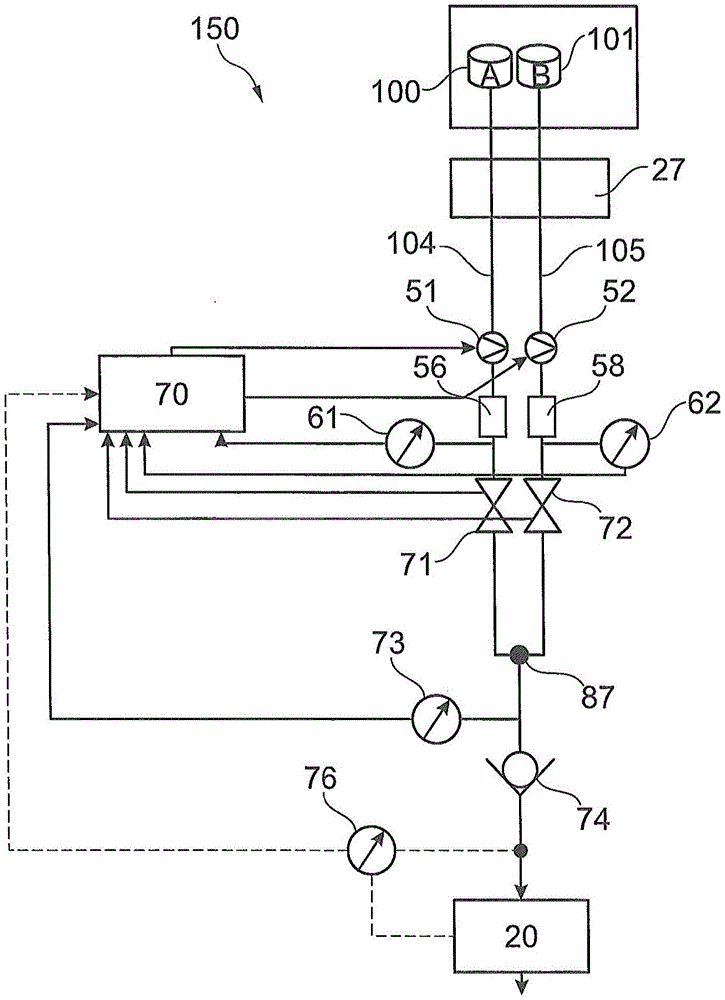
图1示出了作为根据本发明的示例性实施例的液相色谱样品分离设备10的示例的HPLC系统的原理结构,其可以用于例如液相色谱中。供应有来自供应装置25的溶剂的流体输送装置20驱动流动相通过包含固定相的样品分离装置30(比如色谱柱)。供应装置25具有用于提供第一流体(例如水)的第一流体组分源100和用于提供另一第二流体(例如有机溶剂)的第二流体组分源101。可选的脱气器27可以在将由第一流体组分源100和第二流体组分源101提供的溶剂馈送到流体输送装置20之前将其脱气。在流体输送装置20与样品分离装置30之间布置有样品引入单元40(其也称为注射器),以便将样品液体引入流体分离路径。为此,可以相应地切换注射器阀90。提供样品分离装置30的固定相以分离样品的组分。可以包括流动池的检测器50检测所分离的样品组分,并且可以设置分馏装置60来将所分离的样品组分排放到专用容器中。不再需要的液体可以排放到排液容器或废液箱(未示出)。FIG. 1 shows the principle structure of an HPLC system as an example of a liquid chromatography
当流体输送装置20与样品分离装置30之间的流体路径通常处于高压下时,在正常压力下的样品液体首先馈送到与流体路径分离的区域,即样品引入单元40和/或注射器的所谓的样品回路,样品回路转而将样品流体馈送到高压下的流体路径中。在将样品回路中的、最初处于正常压力下的样品液体馈送到处于高压下的液体路径期间,使样品回路的内容物达到HPLC样品分离设备10的系统压力。控制单元70控制样品分离设备10的各个部件20、25、30、40、50、60。When the fluid path between the
图1还示出了液相色谱流体供应设备150,其用于提供多种不同流体的混合物,以作为液相色谱样品分离设备10的溶剂组合物和/或流动相。在所示的实施例中,流体供应设备150具有两个供应管线104、105,其中的每一个都流体耦合到两个溶剂容器中的相应一个,这两个溶剂容器配置为流体组分源100、101,以用于提供流体和/或溶剂组分A和B中的相应一种。例如,溶剂组分A是水,而溶剂组分B是有机溶剂(例如乙醇、甲醇或乙腈)。在供应管线104、105中的每一个中实施了相应的流体泵51、52(并且因此与供应管线104、105的相应一个相关联),该流体泵能够由控制装置70控制和切换。更具体地,控制装置70可以在特定时间点开启流体泵51、52中的每一个,以分别输送相关联的溶剂组分A和/或B,或者可以关断以分别停用相关联的溶剂组分A和/或B的当前输送。特别地,控制装置70可以在任何给定的时间点将两个流体泵51、52中的一个开启到最大,而将两个流体泵51和52中的剩余的至少另一个关断。因此,流体泵51、52中的相应一个根据其相应的切换状态(说明性地为“开”或“关”)从流体组分源100、101中的相应一个输送或不输送相应的流体或相应的溶剂组分A和/或B。相应的流体或相应的溶剂组分A和/或B通过相应的供应管线104和/或105、通过脱气器27并且通过相应的流体泵51和/或52输送到混合或合并点87,在该混合或合并点87处,来自供应管线104、105的流体或者溶剂组分A和/或B彼此合并。在也可称为合并点的合并点87处,来自供应管线104、105的流体包因此一起流动,从而形成均匀的溶剂组合物。然后,后者供应到流体输送装置20。FIG. 1 also shows a liquid chromatography
控制装置70控制各个流体泵51、52的切换状态。如果控制装置70将流体泵51、52中的相应一个切换到生效状态或开启状态,则流体可以从相关联的流体组分源100和/或101通过相关联的供应管线104和/或105并且通过主动切换的流体泵51和/或52流动到合并点87。另一方面,如果流体泵51和/或52中的一个在控制装置70的控制下切换到失效和/或关断状态,则其不主动将流体从相关联的流体组分源100和/或101输送到合并点87,这是由于关断的流体泵51和/或52继而表示较高的流体限制,这也防止流体输送装置20将相当量的相关联的流体输送到合并点87。由于相应的通道或流体泵51和/或52在其开启状态下的泵送作用,可以强烈地抑制重力作用,其例如与流体组分源100和/或101的填充水平依赖性相结合或与流体组分源的高度位置相结合。相应的主动切换的流体泵51、52的作用大大超过这种继而可忽略的重力作用。The
图2示出了根据本发明的示例性实施例的流体供应设备150。Figure 2 shows a
如图2所示,流体组分源100和/或101中的流体或溶剂组分A和/或B分别通过供应管线104和/或105输送。在相应的流体到达供应管线104和/或105中的相应一个中的流体泵51、52(如果开启)之前,相应的流体通过脱气器27,以便尽可能地从相应的流体中去除不希望的气泡。然后,相应的流体流动通过(如果打开)相应的可选流体切换阀71和/或72。切换阀71和/或72中的每一个例如可以呈现为流体转子阀,其具有带有流体连接的定子部件和带有相应的流体管线的转子部件。相应的流体继而到达混合或合并点87(例如呈现为流体T型件),并且最终到达在合并点87下游的呈现为高压双活塞泵20的流体输送装置20。流体输送装置20与流体泵51、52一起配置为输送流体并且同时单独地用作用于定量相应流体量的定量装置。可证明地,流体输送装置20在例如1000bar的压力下从合并点87向下游拉动(或抽取)流体。然后,可以将形成的溶剂组合物供应到布置在流体输送装置20下游的样品引入装置40,并且最终供应到样品分离装置30(比照图1)。As shown in Figure 2, fluid or solvent components A and/or B in
流体泵51、52和切换阀71、72由控制单元70来切换。在相应的流体泵51、52和相应的切换阀71、72的生效切换状态下,相应的流体泵51、52主动朝向合并点87挤压来自流体组分源100、101中的相应一个的相应流体。然而,在相应的流体泵51、52或相应的切换阀71、72的失效切换状态下,相应的流体不从流体组分源100、101中的相应一个输送到流体输送装置20。切换阀71、72中的每一个布置在供应管线104、105中的相应一个中,并且分别在打开状态下开启和/或在关闭状态下禁用通过相关联的供应管线104、105的流体的流动。The fluid pumps 51 and 52 and the switching
如果在供应管线104、105中实施可选的切换阀71、72,则流体泵51、52可以连续运行,并且控制装置70对切换阀71或72的切换限定了流体当前从哪个供应管线104或105供应到合并点87。然而,如果可选的切换阀71、72缺失,则控制装置70可以直接将流体泵51、52开启或关断,从而以便选择性地允许或防止流体从相关联的供应管线104和/或105供应到合并点87。If the
设置连接到供应管线104、105并且布置在流体泵51、52的下游的压力传感器61、62,以用于检测指示供应管线104、105中的相应一个中的压力的值。由压力传感器61、62进行的压力测量明确地提供了对各个供应管线104、105的诊断。此外,如图2所示的流体供应设备150具有位于合并点87下游的压力传感器73。压力传感器73也设置在止回阀74的上游,可以呈现为检测在流动路径的该点处的压力值,并且可以将该压力值供应到控制装置70,使得可以基于压力传感器73所检测的压力值来对任何切换误差进行补偿。可证明地,压力传感器73提供信号,该信号指示控制装置70对流体泵51、52和/或切换阀71、72进行切换的定时是否正确。附图标记76表示另一可选的压力传感器,该压力传感器布置在止回阀74下游并且作为压力传感器73的替代或附加地设置用于诊断。
最终,形成为流体输送装置20的入口阀的止回阀74布置在合并点87下游,该止回阀防止流体不希望地从流体传输装置20在朝向合并点87的方向上回流。流体输送装置20可以例如形成为双活塞泵。Finally, a
由于在1bar数量级的低压下可压缩性对流体或溶剂组分A和/或B的重要性是次要的,因此吸入的流体量由流体输送装置20的初级活塞(比照图3)的运动直接确定。因此,根据示例性实施例,将两种泵送作用结合。通道或流体泵51和/或52将相关联的溶剂组分A和/或B主动地推动到流体输送装置20的活塞中,而该活塞有助于支持抽吸作用。Since compressibility is of secondary importance to fluid or solvent components A and/or B at low pressures of the order of 1 bar, the amount of fluid drawn in is directly determined by the movement of the primary piston (compare FIG. 3 ) of the
可选地,但非常有利的是,在根据图2的流体供应设备150中,流体容积56、58可以布置为流体泵51、52与切换阀71、72之间的供应管线104、105中的流体贮存器或压力贮存器。因此,这样的压力贮存器可以位于一方面的流体泵51、52与另一方面的切换阀71、72之间。可以在压力传感器61、62的上游或下游实现呈容积56、58的形式的一个或多个贮存器的布置。通过设置至少一个这样的流体容积56、58,可增加能够达到的输送量,同时可以使流动平稳。此外,该措施促进流体供应设备150快速创建流体组合物。如果附加地实施一个或多个切换阀71、72,则可以设置一个或者多个容积56、58作为压力贮存器,其使得能够通过相应的切换阀71、72并且通过供应管线104、105来甚至更快地抽吸。示例为对于水而言最大速率为100ml/min。压力贮存器也可以至少部分地补偿可选地添加的过滤器。Optionally, but very advantageously, in the
图3示出了根据本发明的示例性实施例的具有流体供应设备150而没有配比阀(参见图4中的附图标记108)的样品分离设备10。因此,在根据图3的实施例中,流体供应设备150没有配比装置108。Figure 3 shows a
图3示出了用于在流体消耗器(在所示示例中,为根据图1的样品分离设备10的样品分离装置30或检测器50)处提供精确并且随时间变化的流体组合物(在所示示例中为流动相)的流体供应设备150。图3中以附图标记199示意性地示出了所提供的流体组合物对样品分离装置30的时间依赖性。例如,使用如图3所示的随时间变化的流体组合物来运行通过具有图3所示特征的梯度曲线199。在梯度曲线199中,流体组分B针对具有流体组分A的混合物的示例的百分比%B根据时间t变化。对于其他应用,例如可能期望来自所有可能的组分A、B、C和D的其他流体组合物。还可以提供随时间恒定的流体组合物,例如在等度分离模式下。FIG. 3 shows a method for providing a precise and time-varying fluid composition at a fluid consumer (in the illustrated example, the
馈送装置25具有根据图3所示的四个供应管线104至107,其中的每一个流体耦合到四个流体组分源100至103中的相应一个,以用于提供相应的流体组分A至D。各个流体包到达合并点87。The
控制装置70以通道专用的方式控制四个供应管线104至107中的流体泵51至54中的每一个,使得组分A、B、C和D中的一个或一些(例如,根据梯度曲线199的组分A和B)的流体包的序列相继流动通过入口阀113并且通过初级活塞泵111的入口189。The
初级活塞泵111(同样参见附图标记“I”)具有初级活塞115,馈送装置25可以将待泵送的、具有随时间变化的溶剂组合物的流体成包地供应到该初级活塞泵,该初级活塞可以以往复运动的方式布置在用于泵送流体的初级活塞室117中。初级活塞115以及布置在初级活塞泵111与次级活塞泵112之间的流体阀114(在流体连接管线187中)(同样参见附图标记“II”)也能够由控制装置70控制,以用于实现或防止两个活塞泵111、112之间流体连通。然而,流体阀114也可以被动地呈现。次级活塞泵112可以通过使流体打开流体阀114而被供应有由初级活塞泵111泵送的流体。次级活塞泵112具有次级活塞118,该次级活塞以往复运动的方式布置在次级活塞室120中以泵送流体,并且该次级活塞也能够由控制装置70来控制,并且在其出口180处提供流体,该流体通过流体管线121流动到注射器40并且最终进入样品分离装置30,然后进入检测器50。The primary piston pump 111 (see also reference numeral "I") has a
因此,流体供应设备150用于供应对具有流动相的流体样品进行分离的样品分离设备10(其包括样品分离装置30和检测器50)。流体样品通过注射器和/或样品引入单元40通过注射器阀90的相应回路引入/插入到流动相中。Thus, the
根据图3,控制装置70用于控制整个样品分离设备10、特别是活塞泵111、112、阀113、114和注射器阀90以及流体泵51至54。根据图3,流体输送装置20配置为高压泵,以用于以例如1200bar的压力递送流动相。According to FIG. 3 , the
因此,图3示出了实施例示例,其中,在不设置配比装置108的情况下实现了精确的流体组合物(比照图4)。替代地,根据图3,流体组合物简单地通过启动四个流体泵51至54中的一个来实现,并且同时支持流体输送装置20的抽吸动作。由于未在某一时间点启动的所有流体泵51至54形成如此高的流体阻力,使得通过相关联的供应管线104至107输送的流体A、B、C或D可以忽略,因此可以通过启动或开启流体泵51至54中的一个来对要在某一时间点泵送的流体A、B、C或D进行选择。Thus, Figure 3 shows an example of an embodiment in which a precise fluid composition is achieved without the provision of a proportioning device 108 (compare Figure 4). Alternatively, according to FIG. 3 , the fluid composition is simply achieved by activating one of the four
图4示出了根据本发明的另一示例性实施例的具有流体供应设备150的样品分离设备10,该流体供应设备具有配比阀108。在图4的实施例中,流体供应设备150还具有带有配比阀的配比装置108,并且用于配比由供应管线104至107所供应的流体中的相应一种的包。FIG. 4 shows a
配比装置108布置在供应管线104至107与初级活塞泵111的入口189之间。配比装置108能够由控制装置70来控制,以用于通过将供应管线104至107中选定的供应管线顺序地耦合至初级活塞泵111而调节来自初级活塞泵111上游的流体组分A至D的包的流体的组合物。The proportioning device 108 is arranged between the
这意味着控制装置70以如此方式控制配比装置108(特别是根据多路复用方案),使得组分A、B、C和D中的一种或一些(例如根据梯度曲线199的组分A和B)的流体包的序列相继流动通过入口阀113并且通过初级活塞泵111的入口189。在此之前,各个流体包到达配比装置108的出口处的合并点87。This means that the
根据图4,建立了更精确地提供溶剂组合物的流体供应设备150。根据图4的实施例与根据图3的实施例的不同之处在于,现在设置了配比装置108。根据配比装置108的切换阀(参见图2中的附图标记71、72)的切换状态,配比装置108在任何给定的时间将合并点87流体耦合到供应管线104至107中的仅仅一个。通过这种方式,根据图4,流体泵51至54形式的多通道梯度泵的原理可以可证明地与配比装置108形式的多通道梯度阀的原理协同地结合。配比装置108于是可以主动地打开和/或关闭流体的流动路径,并且因此可以为每个单独的通道提供阀作用。According to Fig. 4, a
图5示出了根据本发明的示例性实施例的诊断系统,该诊断系统用于诊断样品分离设备10的各个部件的操作状况。可以在根据图1至图4的实施例中的任意一个中实施诊断系统。FIG. 5 illustrates a diagnostic system for diagnosing the operating conditions of various components of the
根据图5的原理可以称为用于对HPLC中的主动和被动切换阀进行诊断和/或状态检测的方法。在HPLC中,高压四元泵的摄入流量取决于对泄压点的精确确定。这对应于泵的入口阀打开的时间点。在抽吸阶段期间,泵的初级活塞的体积泄压,直到压力对应于环境压力。从这个时间点起,活塞的任何运动都不再压缩流体。替代地,流体被吸入。如果没有确定这个确切的时间点,则计算出的新抽吸流体量将出现误差。The principles according to FIG. 5 can be referred to as a method for diagnosis and/or status detection of active and passive switching valves in HPLC. In HPLC, the intake flow of the high pressure quaternary pump depends on the precise determination of the pressure relief point. This corresponds to the point in time when the inlet valve of the pump is opened. During the suction phase, the volume of the primary piston of the pump is depressurized until the pressure corresponds to the ambient pressure. From this point in time, any movement of the piston no longer compresses the fluid. Instead, fluid is sucked in. If this exact point in time is not determined, there will be an error in the calculation of the newly drawn fluid volume.
跟踪入口阀和/或切换阀、梯度阀、转子阀或被动/主动阀打开或关闭的时刻完成了确定。因此,可以实施主动地减少摄入(或抽吸)误差的控制算法。因此,可以减小所确定的阀打开时刻与实际打开时刻之间的延迟。如果实际打开时间用于定量,则组合物变得更准确。Tracking the moment when the inlet valve and/or switching valve, gradient valve, rotor valve or passive/active valve is opened or closed completes the determination. Thus, a control algorithm that actively reduces intake (or aspiration) errors can be implemented. Therefore, the delay between the determined valve opening time and the actual opening time can be reduced. The composition becomes more accurate if the actual open time is used for dosing.
为了减少误差,只计算泄压点。然而,干扰会恶化或破坏这种确定。To reduce errors, only the pressure relief point is calculated. However, interference can worsen or destroy this determination.
根据本文所述的示例性实施例,假设入口阀的运动在液体内部或外部生成可检测的噪声、脉冲、加速度、振动和压力变化。这些值可以在图2中的合并点87之前和之后由压力传感器测量,参见那里的压力传感器61、62、73、76。可以检测由作用阀引起的压力波动。还可以在入口阀之前和/或之后检测流体柱内的水听器作用。水听器是可以检测流体中的噪声的装置。当完成此操作时,观测到来自系统的其他信号,例如泵的状况、轴承的状况、阀的切换位置、气穴作用等。还可以提供跟踪阀的运动脉冲的加速度计。阀门的打开和关闭引起可检测的脉冲,这是由于阀门必须移动内部零件。According to the exemplary embodiments described herein, it is assumed that movement of the inlet valve generates detectable noise, pulses, accelerations, vibrations and pressure changes inside or outside the liquid. These values can be measured by pressure sensors before and after the
所述监测的另一优点如下:连接或联接泵和/或泵头和/或多通道梯度阀和/或入口阀的刚性或液体主体允许通过减少数量的传感器来进一步改进诊断和控制。例如,可以将水听器或麦克风或加速度计布置在刚性或液体主体中或附近,并且监测来自泵单元的所有连接零件的噪声。Another advantage of the monitoring is as follows: The rigid or liquid body connecting or coupling the pump and/or the pump head and/or the multi-channel gradient valve and/or the inlet valve allows further improved diagnostics and control with a reduced number of sensors. For example, a hydrophone or a microphone or an accelerometer can be arranged in or near the rigid or liquid body and monitor the noise from all connected parts of the pump unit.
图5示出了具有适当诊断能力的布置的示例。附图标记200、202、204、206指代四个阀(例如,与切换阀71、72一样地实施)。附图标记210、212和214指代相关联的传感器、特别是声音传感器。附图标记220表示泵和/或泵头、压力室、入口阀和/或出口阀。Figure 5 shows an example of an arrangement with suitable diagnostic capabilities.
通过所描述的诊断功能,可以确定电机和泵的反向点。替换地或附加地,可以确定相互接合的零件在其移动时的间隙。可以检测气穴作用。可以检测被动阀和主动阀的关闭和/或打开。而且,可以通过三角测量法来确定机械或流体事件的位置。With the described diagnostic functions, the reversal point of the motor and pump can be determined. Alternatively or additionally, the clearance of the mutually engaging parts as they move can be determined. Cavitation can be detected. Closing and/or opening of passive and active valves can be detected. Also, the location of mechanical or fluid events can be determined by triangulation.
需要注意,术语“具有”并不排除其他元件,而“一”或“一个”也不排除多个。同样,可以对结合不同实施例示例描述的元件进行组合。还应当注意,权利要求中的附图标记不应当解释为限制权利要求的保护范围。It should be noted that the term "having" does not exclude other elements, nor does "a" or "an" exclude a plurality. Likewise, elements described in connection with different embodiment examples may be combined. It should also be noted that reference signs in the claims shall not be construed as limiting the scope of protection of the claims.
Claims (20)
Applications Claiming Priority (3)
| Application Number | Priority Date | Filing Date | Title |
|---|---|---|---|
| DE102018104842.4A DE102018104842A1 (en) | 2018-03-02 | 2018-03-02 | Fluid mixing by means of fluid supply lines with line-specific associated fluid pumps for liquid chromatography |
| DE102018104842.4 | 2018-03-02 | ||
| PCT/IB2019/051661 WO2019167011A1 (en) | 2018-03-02 | 2019-03-01 | Fluid mixing by means of fluid supply lines with line-specifically associated fluid pumps for liquid chromatography |
Publications (1)
| Publication Number | Publication Date |
|---|---|
| CN111801495A true CN111801495A (en) | 2020-10-20 |
Family
ID=61764962
Family Applications (1)
| Application Number | Title | Priority Date | Filing Date |
|---|---|---|---|
| CN201980016428.6A Pending CN111801495A (en) | 2018-03-02 | 2019-03-01 | Fluid mixing by fluid supply lines with line-specific fluid pumps for liquid chromatography |
Country Status (4)
| Country | Link |
|---|---|
| US (1) | US20200400623A1 (en) |
| CN (1) | CN111801495A (en) |
| DE (1) | DE102018104842A1 (en) |
| WO (1) | WO2019167011A1 (en) |
Families Citing this family (12)
| Publication number | Priority date | Publication date | Assignee | Title |
|---|---|---|---|---|
| US11185830B2 (en) | 2017-09-06 | 2021-11-30 | Waters Technologies Corporation | Fluid mixer |
| CN111433600B (en) * | 2018-03-16 | 2022-07-22 | 株式会社岛津制作所 | Binary pump and liquid chromatograph provided with same |
| ES2915839T3 (en) * | 2019-06-04 | 2022-06-27 | Hoffmann La Roche | Rapid Liquid Exchange in Liquid Chromatography |
| WO2021030245A1 (en) | 2019-08-12 | 2021-02-18 | Waters Technologies Corporation | Mixer for chromatography system |
| DE102020102297A1 (en) | 2020-01-30 | 2021-08-05 | Agilent Technologies, Inc. - A Delaware Corporation - | Rocker valve with sealing element |
| EP4179311B1 (en) | 2020-07-07 | 2025-07-30 | Waters Technologies Corporation | Combination mixer arrangement for noise reduction in fluid chromatography |
| US11898999B2 (en) | 2020-07-07 | 2024-02-13 | Waters Technologies Corporation | Mixer for liquid chromatography |
| EP4217729B1 (en) | 2020-09-22 | 2025-08-13 | Waters Technologies Corporation | Continuous flow mixer |
| EP4070667A1 (en) * | 2021-04-07 | 2022-10-12 | LANXESS Deutschland GmbH | Method and device for preserving drinks |
| WO2022245566A1 (en) | 2021-05-20 | 2022-11-24 | Waters Technologies Corporation | Equal dispersion split-flow mixer |
| JP2023158426A (en) * | 2022-04-18 | 2023-10-30 | 株式会社島津製作所 | Mobile phase delivery system and mobile phase delivery method |
| CN117072431B (en) * | 2023-10-17 | 2024-01-12 | 北京豪思生物科技股份有限公司 | Infusion pump detection device and detection method for liquid chromatograph |
Citations (7)
| Publication number | Priority date | Publication date | Assignee | Title |
|---|---|---|---|---|
| CN101281177A (en) * | 2007-04-03 | 2008-10-08 | 株式会社岛津制作所 | Liquid chromatography |
| WO2009092345A1 (en) * | 2008-01-25 | 2009-07-30 | Dionex Softron Gmbh | Sample dispenser for liquid chromatography, particularly for high-performance liquid chromatography |
| CN202693596U (en) * | 2011-02-09 | 2013-01-23 | 安捷伦科技有限公司 | Liquid supply system with optimized switching between different solvents |
| CN103336066A (en) * | 2013-01-15 | 2013-10-02 | 刘冠琳 | Urinary calculus etiological diagnosis system with multi-channel sample feeding function and applications thereof |
| WO2014066769A1 (en) * | 2012-10-25 | 2014-05-01 | Alltech Associates, Inc. | Pump priming systems |
| US20150219603A1 (en) * | 2014-02-06 | 2015-08-06 | Waters Technologies Corporation | Method for high pressure gradient chromatography using pump stroke control |
| US20150345484A1 (en) * | 2012-09-11 | 2015-12-03 | Warner DÖBELIN | Syringe pump system for pulse-free metering and precise mixing in hplc uhplc, micro-hplc and nano-hplc |
Family Cites Families (35)
| Publication number | Priority date | Publication date | Assignee | Title |
|---|---|---|---|---|
| US3917531A (en) * | 1974-02-11 | 1975-11-04 | Spectra Physics | Flow rate feedback control chromatograph |
| US4128476A (en) * | 1977-06-14 | 1978-12-05 | Spectra-Physics, Inc. | Carrier composition control for liquid chromatographic systems |
| US4116046A (en) * | 1977-08-05 | 1978-09-26 | Hoffmann-La Roche Inc. | Liquid chromatography system |
| US4389163A (en) * | 1979-01-02 | 1983-06-21 | Altex Scientific, Inc. | Pressure booster system for fluids |
| US4311586A (en) * | 1980-04-22 | 1982-01-19 | Tracor, Inc. | Solvent mixing in HPLC using low pressure solvent metering pumps |
| US4427298A (en) * | 1982-09-30 | 1984-01-24 | E. I. Du Pont De Nemours And Company | Method and system for accurately providing fluid blends |
| US4595496A (en) * | 1984-06-29 | 1986-06-17 | Millipore Corporation | Liquid composition control |
| US4981597A (en) * | 1986-03-10 | 1991-01-01 | Isco, Inc. | Gradient system |
| US5180487A (en) * | 1987-09-25 | 1993-01-19 | Nihon Bunko Kogyo Kabushiki Kaisha | Pump apparatus for transferring a liquified gas used in a recycle chromatograph |
| EP0309596B1 (en) | 1987-09-26 | 1993-03-31 | Hewlett-Packard GmbH | Pumping apparatus for delivering liquid at high pressure |
| US4963075A (en) * | 1988-08-04 | 1990-10-16 | The Charles Machine Works, Inc. | Radial diaphragm pump |
| US5360320A (en) * | 1992-02-27 | 1994-11-01 | Isco, Inc. | Multiple solvent delivery system |
| US5664938A (en) * | 1992-03-05 | 1997-09-09 | Yang; Frank Jiann-Fu | Mixing apparatus for microflow gradient pumping |
| US5253981A (en) * | 1992-03-05 | 1993-10-19 | Frank Ji-Ann Fu Yang | Multichannel pump apparatus with microflow rate capability |
| FR2726332B1 (en) * | 1994-10-26 | 1997-01-24 | Francois Couillard | PISTON PUMPING SYSTEM DELIVERING FLUIDS WITH SUBSTANTIALLY CONSTANT FLOW RATE |
| JP3534944B2 (en) * | 1996-06-05 | 2004-06-07 | ジーエルサイエンス株式会社 | Liquid chromatograph mixer |
| US6475388B1 (en) * | 1996-11-13 | 2002-11-05 | Transgenomic, Inc. | Method and system for RNA analysis by matched ion polynucleotide chromatography |
| US6427526B1 (en) * | 2001-02-27 | 2002-08-06 | Isco, Inc. | Liquid chromatographic method and system |
| US6648609B2 (en) * | 2002-04-05 | 2003-11-18 | Berger Instruments, Inc. | Pump as a pressure source for supercritical fluid chromatography involving pressure regulators and a precision orifice |
| US6780315B2 (en) * | 2002-12-09 | 2004-08-24 | Waters Investments Limited | Backflow prevention for high pressure gradient systems |
| JP4887295B2 (en) * | 2004-08-24 | 2012-02-29 | ウオーターズ・テクノロジーズ・コーポレイシヨン | Apparatus, system, and method for pump and injector synchronization to compensate flow |
| FR2882530B1 (en) * | 2005-02-25 | 2007-05-25 | Pic Solution Soc Par Actions S | METHOD AND DEVICE FOR DELIVERING A MIXTURE OF FLUIDS AT HIGH PRESSURE AND USING THE METHOD |
| ITVE20070072A1 (en) * | 2007-10-16 | 2009-04-17 | Dani Instr Spa | DEVICE FOR THE GENERATION OF MOBILE PHASE GRADIENTS WITH MICRO- AND NANOFLUSSI FOR HIGH-PERFORMANCE LIQUID CHROMATOGRAPHY. |
| CN102112741B (en) * | 2008-08-07 | 2016-01-13 | 安捷伦科技有限公司 | Synchronization of supply streams |
| CN102549516A (en) * | 2009-09-25 | 2012-07-04 | 通用电气健康护理生物科学股份公司 | Method and system for the preparation of liquid mixtures |
| US9417219B2 (en) * | 2009-11-16 | 2016-08-16 | Agilent Technologies, Inc. | Sample separation device with valve |
| US9645123B2 (en) * | 2010-01-11 | 2017-05-09 | Waters Technologies Corporation | Manifold for solvent mixing in liquid chromatography systems |
| US20120205314A1 (en) * | 2010-08-13 | 2012-08-16 | Davison Dale A | Gradient start up system |
| US9459239B2 (en) * | 2011-07-08 | 2016-10-04 | Agilent Technologies, Inc. | Intake monitoring for accurate proportioning |
| US10238989B2 (en) * | 2011-12-14 | 2019-03-26 | Waters Technologies Corporation | Hybrid gradient delivery system and operation |
| DE102012010544B4 (en) * | 2012-05-29 | 2017-02-09 | J. Wagner Ag | Method and apparatus for mixing at least two liquid components |
| WO2015121425A1 (en) * | 2014-02-14 | 2015-08-20 | Ge Healthcare Bio-Sciences A B | Automated multi-step purification system |
| US10926191B2 (en) * | 2014-12-12 | 2021-02-23 | Cytiva Sweden Ab | System for preparing solutions for chromatography |
| EP3234588B1 (en) * | 2014-12-17 | 2024-03-06 | Cytiva Sweden AB | System for blending solutions |
| JP6696578B2 (en) * | 2016-09-26 | 2020-05-20 | 株式会社島津製作所 | Changeover valve, binary pump and liquid chromatograph equipped with the binary pump |
-
2018
- 2018-03-02 DE DE102018104842.4A patent/DE102018104842A1/en active Pending
-
2019
- 2019-03-01 CN CN201980016428.6A patent/CN111801495A/en active Pending
- 2019-03-01 US US16/977,798 patent/US20200400623A1/en active Pending
- 2019-03-01 WO PCT/IB2019/051661 patent/WO2019167011A1/en not_active Ceased
Patent Citations (7)
| Publication number | Priority date | Publication date | Assignee | Title |
|---|---|---|---|---|
| CN101281177A (en) * | 2007-04-03 | 2008-10-08 | 株式会社岛津制作所 | Liquid chromatography |
| WO2009092345A1 (en) * | 2008-01-25 | 2009-07-30 | Dionex Softron Gmbh | Sample dispenser for liquid chromatography, particularly for high-performance liquid chromatography |
| CN202693596U (en) * | 2011-02-09 | 2013-01-23 | 安捷伦科技有限公司 | Liquid supply system with optimized switching between different solvents |
| US20150345484A1 (en) * | 2012-09-11 | 2015-12-03 | Warner DÖBELIN | Syringe pump system for pulse-free metering and precise mixing in hplc uhplc, micro-hplc and nano-hplc |
| WO2014066769A1 (en) * | 2012-10-25 | 2014-05-01 | Alltech Associates, Inc. | Pump priming systems |
| CN103336066A (en) * | 2013-01-15 | 2013-10-02 | 刘冠琳 | Urinary calculus etiological diagnosis system with multi-channel sample feeding function and applications thereof |
| US20150219603A1 (en) * | 2014-02-06 | 2015-08-06 | Waters Technologies Corporation | Method for high pressure gradient chromatography using pump stroke control |
Also Published As
| Publication number | Publication date |
|---|---|
| WO2019167011A1 (en) | 2019-09-06 |
| DE102018104842A1 (en) | 2018-04-19 |
| WO2019167011A4 (en) | 2019-10-31 |
| US20200400623A1 (en) | 2020-12-24 |
Similar Documents
| Publication | Publication Date | Title |
|---|---|---|
| CN111801495A (en) | Fluid mixing by fluid supply lines with line-specific fluid pumps for liquid chromatography | |
| US7578173B2 (en) | Chromatography system with flow sensing | |
| CN105308448B (en) | Metering device switchable between different fluid paths cleaned by solvent from the analytical path of the fluid separation system | |
| US10641746B2 (en) | Sample injection with fluidic connection between fluid drive unit and sample accommodation volume | |
| US11567040B2 (en) | Injector with fluid supply and mobile phase discharge | |
| US7980119B2 (en) | Auto-sampler cleaning mechanism | |
| US9459239B2 (en) | Intake monitoring for accurate proportioning | |
| US20120198919A1 (en) | Liquid supply with optimized switching between different solvents | |
| JP6309439B2 (en) | Hemoglobin analyzer | |
| CN112888941B (en) | Injectors for multi-dimensional sample separation devices | |
| JP2015092166A5 (en) | ||
| JP4077674B2 (en) | Gradient liquid feeding device and liquid feeding method for nano / micro liquid chromatograph | |
| US7985198B2 (en) | Device and process for metering solutions | |
| US20240230455A1 (en) | Determining a restriction in a liquid network | |
| CN116529594A (en) | Testing a sampling unit fluidly coupled to a source | |
| CN120831435A (en) | Sample separation device with active damping metering device | |
| CN113167774B (en) | Remove uncertain composition fraction from mobile phase | |
| GB2593061A (en) | Two-dimensional fluid separation with push-pull modulation | |
| US20230194008A1 (en) | Fluidic valve supporting additional movement in addition to opening and closing movement | |
| WO2012149956A1 (en) | Flow stabilization by capacitive load | |
| CN120752528A (en) | Fault location estimation method and liquid chromatography |
Legal Events
| Date | Code | Title | Description |
|---|---|---|---|
| PB01 | Publication | ||
| PB01 | Publication | ||
| SE01 | Entry into force of request for substantive examination | ||
| SE01 | Entry into force of request for substantive examination |