CN111798476A - A method for extracting the axis of the conductive arm of a high-voltage isolation switch - Google Patents
A method for extracting the axis of the conductive arm of a high-voltage isolation switch Download PDFInfo
- Publication number
- CN111798476A CN111798476A CN202010510134.3A CN202010510134A CN111798476A CN 111798476 A CN111798476 A CN 111798476A CN 202010510134 A CN202010510134 A CN 202010510134A CN 111798476 A CN111798476 A CN 111798476A
- Authority
- CN
- China
- Prior art keywords
- conductive arm
- image
- isolating switch
- voltage isolating
- edge
- Prior art date
- Legal status (The legal status is an assumption and is not a legal conclusion. Google has not performed a legal analysis and makes no representation as to the accuracy of the status listed.)
- Granted
Links
Images


Classifications
-
- G—PHYSICS
- G06—COMPUTING OR CALCULATING; COUNTING
- G06T—IMAGE DATA PROCESSING OR GENERATION, IN GENERAL
- G06T7/00—Image analysis
- G06T7/10—Segmentation; Edge detection
- G06T7/13—Edge detection
-
- G—PHYSICS
- G06—COMPUTING OR CALCULATING; COUNTING
- G06T—IMAGE DATA PROCESSING OR GENERATION, IN GENERAL
- G06T7/00—Image analysis
- G06T7/10—Segmentation; Edge detection
- G06T7/181—Segmentation; Edge detection involving edge growing; involving edge linking
-
- G—PHYSICS
- G06—COMPUTING OR CALCULATING; COUNTING
- G06T—IMAGE DATA PROCESSING OR GENERATION, IN GENERAL
- G06T2207/00—Indexing scheme for image analysis or image enhancement
- G06T2207/10—Image acquisition modality
- G06T2207/10004—Still image; Photographic image
Landscapes
- Engineering & Computer Science (AREA)
- Computer Vision & Pattern Recognition (AREA)
- Physics & Mathematics (AREA)
- General Physics & Mathematics (AREA)
- Theoretical Computer Science (AREA)
- Image Analysis (AREA)
Abstract
The invention discloses a method for extracting an axis of a conductive arm of a high-voltage isolating switch, which comprises the following steps: step 1, collecting and processing complete image data of a conductive arm of a high-voltage isolating switch; step 2, calculating an image edge linear equation of the conductive arm of the high-voltage isolating switch; step 3, calculating a normal vector of the light tangent plane; and 4, determining the axial direction of the conductive arm by intersecting the symmetry planes. The invention takes close-range photogrammetry and image recognition technology as means, realizes the automatic extraction of the axis of the conductive arm of the high-voltage isolating switch, and can provide a new technical means for the charged non-contact automatic measurement of the included angle of the conductive arm of the high-voltage isolating switch and the automatic recognition of the switching-on state of the high-voltage isolating switch.
Description
Technical Field
The invention relates to the technical field of transformer substations, in particular to a method for extracting an axis of a conductive arm of a high-voltage isolating switch.
Background
The high-voltage isolating switch drives the moving contact to realize contact and separation with the fixed contact by the operating mechanism. The high-voltage isolating switch is very easily influenced by the environment when the high-voltage isolating switch operates outdoors, and the operation and maintenance of the operating mechanism are not timely, so that the high-voltage isolating switch is not switched on in place due to rusting and jamming of the operating mechanism, a gap is formed, heating or even discharging is caused, the service life of equipment is influenced, and the safe operation of a power grid is threatened.
The field operation experience shows that the defect that the on-site typical concealment and great harm are caused when the high-voltage isolating switch is not closed in place, and theoretical research shows that the on-site state of the high-voltage isolating switch can be effectively judged by measuring the included angle of the conductive arm. According to the definition of the included angle of the conductive arm, how to extract the axis of the conductive arm is a key step of measuring the included angle of the conductive arm and judging whether the high-voltage isolating switch is switched on in place.
In the prior art, the lack of detection and diagnosis technology for the high-voltage isolating switch mainly takes experience judgment as a main part, and a feasible method for extracting the axis of the conducting arm of the high-voltage isolating switch is not available, so that whether the high-voltage isolating switch is in a normal switching-on state completely depends on the subjective experience of personnel, and misjudgment is easily caused.
Disclosure of Invention
Therefore, the invention aims to provide an axis extraction method for a conductive arm of a high-voltage isolating switch, so as to realize automatic extraction of the axis of the conductive arm of the high-voltage isolating switch, and provide a new technical means for automatic charged non-contact measurement of an included angle of the conductive arm of the high-voltage isolating switch and automatic identification of a switching-on state of the high-voltage isolating switch.
A method for extracting an axis of a conductive arm of a high-voltage isolating switch comprises the following steps:
step 1, collecting and processing complete image data of a conductive arm of a high-voltage isolating switch;
step 2, calculating an image edge linear equation of the conductive arm of the high-voltage isolating switch;
step 3, calculating a normal vector of the light tangent plane;
and 4, determining the axial direction of the conductive arm by intersecting the symmetry planes.
In addition, the method for extracting the axis of the conductive arm of the high-voltage isolating switch, provided by the invention, also has the following technical characteristics:
further, step 1 specifically includes:
step 1.1, selecting feature points, selecting 3 or more than 3 suitable feature points on or near a conductive arm of a high-voltage isolating switch as homonymy points, wherein the homonymy points are image points of the same point on different images of an object, selecting points which are easy to identify and accurate to position as the feature points by taking a design drawing of the high-voltage isolating switch as reference, and requiring the relative position of the feature points on the high-voltage isolating switch to be determined;
step 1.2, selecting a shooting position, selecting a proper shooting point near the high-voltage isolating switch equipment to shoot complete image data of the high-voltage isolating switch conductive arm, wherein the conductive arm is required to be not shielded and comprises the selected characteristic point;
step 1.3, multiple operations are carried out, the high-voltage isolating switch conducting arm is shot at other angles and positions, the shooting requirement is the same as that of step 1.2, at least two groups of image data are needed for the same conducting arm, and data of more than two groups can be subjected to adjustment processing, so that errors are reduced;
step 1.4, image edge detection is carried out, the image is converted into a gray image, the gray image is processed by using a canny edge detection algorithm, and edge data of the shot image is obtained through the steps of smooth filtering, gradient calculation, non-maximum value inhibition and edge detection;
and step 1.5, screening the edge image, removing the edge irrelevant to the conductive arm and the characteristic point from the image, and respectively reserving the edge image of the conductive arm and the edge image of the characteristic point.
Further, step 2 specifically includes:
step 2.1, converting a coordinate system, namely converting a pixel coordinate system of the digital image into an image plane coordinate system;
step 2.2, resolving exterior orientation elements, and resolving exterior orientation elements of corresponding images by a pyramid method according to the position information of the characteristic points, wherein the exterior orientation elements comprise exterior orientation line elements and exterior orientation angle elements of the images;
2.3, separating the outlines, namely separating according to the edge images of the conductive arm and respectively calculating linear equations of the contour lines on the two sides of the conductive arm;
and 2.4, calculating a linear equation of the edge of the conductive arm, and respectively fitting the linear equation of the edge image of the conductive arm by using the coordinate values of the pixel points in the image as objects and utilizing a least square method.
Further, step 3 specifically includes:
step 3.1, performing reduction on pixel points of the edge image of the conductive arm, and performing reduction on pixel point coordinates of the edge line according to the fitted linear equation and the pixel coordinate value of the image to obtain new pixel point coordinates of the edge line;
step 3.2, calculating normal vectors of the light ray tangent planes, taking an edge straight line of the conductive arm as an object, randomly taking two pixel point coordinates after calculation on the straight line, and calculating two light ray tangent planes P1、P2The normal vector of (a);
step 3.3, the normal vector directions of the light ray tangent planes are uniform, and the orientations of the light ray tangent planes are compared by P1、P2The orientation of any one plane is taken as a reference, and if the orientation of the other plane is opposite to that of the reference plane, the normal amount of the plane is takenAnd reversing.
Further, step 4 specifically includes:
step 4.1, calculating a normal vector of the symmetry plane, and calculating a normal vector of the symmetry plane P where the axis of the conductive arm and the shooting point are located by taking the two light tangent plane normal vectors obtained in the step 3 as data;
step 4.2, calculating another set of normal vectors of the symmetry plane, re-taking another set of data, repeating the step 1, the step 2 and the step 3, and correspondingly obtaining the normal vectors of the symmetry plane where the axes of the set of conductive arms and the shooting point are located;
and 4.3, calculating the axial direction vector of the conductive arm, and according to the principle that the intersection line of the two planes is perpendicular to the normal vectors of the two planes respectively and the normal vectors of the symmetrical planes obtained in the steps 4.1 and 4.2, calculating the axial direction vector of the conductive arm to finish the axial extraction of the conductive arm.
According to the method for extracting the axis of the conductive arm of the high-voltage isolating switch, provided by the invention, the automatic extraction of the axis of the conductive arm of the high-voltage isolating switch is realized by taking close-range photogrammetry and an image recognition technology as means, and the method can be used as an effective detection tool for a rapid detection technology of the switching-on state of the high-voltage isolating switch, and has the following effective effects:
1) by constructing a physical model for shooting the conductive arm, the mathematical relationship among a light tangent plane normal vector, a symmetric plane normal vector and a conductive arm axial direction vector is analyzed, a mode of calculating the symmetric plane normal vector in a mode of synthesizing the two light tangent plane normal vectors is provided, and a mode of extracting the cylindrical axis of the conductive arm is further extracted by a vector product between two different symmetric plane normal vectors;
2) by taking close-range photogrammetry, image recognition and edge detection as means, pixel point coordinates of an edge image are obtained by calculating a linear equation of the edge of a conductive arm in the image, a normal vector of a light tangent plane is determined, and a virtual light tangent plane normal vector calculation problem is converted into a real image pixel point coordinate problem;
3) the method for extracting the characteristic points on the basis of the self structure of the high-voltage isolating switch is provided, so that the difficulty caused by adding marks on the electrified equipment is avoided;
4) the problem of coordinate step property of the pixel point of the digital image is solved by using a least square method, and the precision is improved.
Drawings
The above and/or additional aspects and advantages of embodiments of the present invention will become apparent and readily appreciated from the following description of the embodiments, taken in conjunction with the accompanying drawings of which:
FIG. 1 is a schematic diagram showing the relationship between object points, shooting points and image points;
FIG. 2 is a schematic diagram of an equivalent model of a photographic conductive arm;
FIG. 3 is a schematic diagram of a pixel coordinate system and an image plane coordinate system;
FIG. 4 is a schematic view of a line in a digital image;
fig. 5 is a schematic flow chart of a method for extracting the axis of the conductive arm of the high-voltage isolating switch.
Detailed Description
In order to make the objects, technical solutions and advantages of the embodiments of the present invention clearer, the technical solutions in the embodiments of the present invention will be clearly and completely described below with reference to the drawings in the embodiments of the present invention, and it is obvious that the described embodiments are some, but not all, embodiments of the present invention. All other embodiments, which can be derived by a person skilled in the art from the embodiments given herein without making any creative effort, shall fall within the protection scope of the present invention.
Before explaining the method for extracting the axis of the conductive arm of the high-voltage disconnecting switch, the technical principle of the method is firstly introduced.
The collinear conditional equation describes a conditional equation in which the image point, the projected center point S, and the object point should be on the same straight line. Most of the solution methods in close range photogrammetry are based on collinear condition equations, as shown in formula 1.
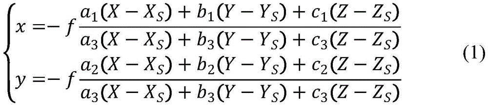
Wherein x, y are coordinates of image points in an image plane coordinate systemThe origin o is a principal point, which is represented as a projection point of the shooting point S to the image plane, and the distance f from the shooting point S to the image plane M' is a principal distance, as shown in fig. 1. X, Y and Z are the coordinates of an object space coordinate system S-XYZ object space point, XS,YS,ZSIs the coordinate of a shooting point S in an object space coordinate system, and is an external orientation line element, a1、a2、a3、b1、b2、b3、c1、c2、c3The coordinate system rotation transformation coefficient is the external orientation angle element.
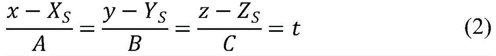
Shooting the cylindrical conductive arm from the shooting point S can be equivalent to a physical model that a point light source emits a beam of light from S to cover and irradiate the cylindrical surface. When the cylindrical axis in the physical model is taken as the Z axis, the circle center of the bottom surface is taken as the origin, and the bottom surface is taken as the XOY plane, a world coordinate system is established. S is the coordinate of the central point of the photograph (X)S,YS,ZS) Cylindrical surface of x2+y2=r2. As shown in fig. 2, any linear parameter equation passing through the point S is:
then:

substituting the cylindrical equation to simplify the formula:
(A2+B2)t2+2(AXS+BYS)t+XS 2+YS 2-r2=0 (4)
when the line is tangent to the cylinder, equation 4 has a unique solution, then:

then:
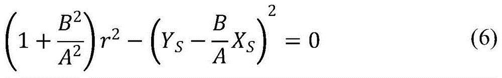
this is a quadratic equation of unity with respect to B/A, so B/A is constant.
The root of the above unary-quadratic equation for t is:

substituting solution x
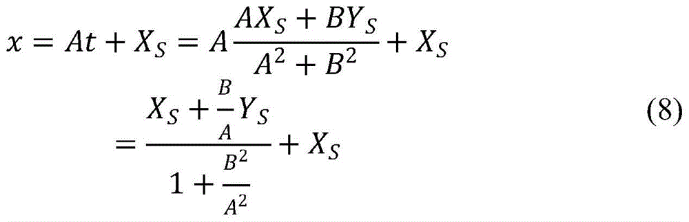
Therefore, in equation 8, x is also constant, and similarly, y is also constant. And z has an unknown parameter value C in its expression, i.e. the value of z is uncertain. Therefore, the boundaries of the cylindrical contour captured by the point S are two straight lines, denoted as l1、l2And the two straight lines are both parallel to the Z axis, i.e. parallel to the cylindrical axis. If the plane formed by the photographing point and the axis of the conductive arm is taken as a plane P, the plane P is a symmetry plane of the cylinder, and the two straight lines l1、l2Symmetrical about the plane of symmetry P, the two tangents are the boundaries of the cylindrical profile as seen from point S. Boundary l1、l2The projections of the passing points S on the image plane are respectively straight lines l'1、l'2As shown in fig. 2.
The digital image is composed of a small square pixel, the side length of one pixel is d, and the calculation mode of any point on the image straight line from the pixel coordinate system to the image plane coordinate system is formula 9.
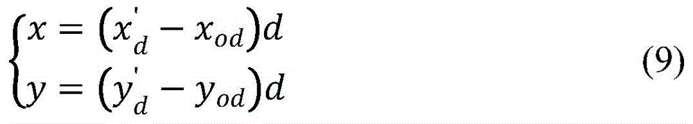
The pixel coordinate system of the digital image is hereby converted into an image plane coordinate system, as shown in fig. 3. Wherein (x'd,y'd) Is the pixel coordinate of any point after being reduced under the pixel coordinate system, (x)od,yod) The coordinate of the origin of the image coordinate system is the pixel coordinate of the pixel coordinate system, and (x, y) are the coordinates of corresponding points of the image coordinate system;
since the pixel points themselves are discrete, there is a step property when forming an image, as shown in fig. 4. When the resolution of the camera is higher, the size of the pixel points is smaller and the pixel points are closer to continuity. Therefore, in order to improve the image calculation accuracy, the invention uses the least square method to the straight line l'1、l'2The coordinates of the pixel points are reduced, so that the pixel points in the digital image are all located on the same straight line, and the step performance is eliminated.
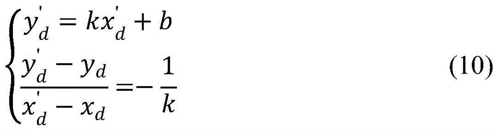
In a straight line l'1For example, the calculation method is as follows: y-kx + b is a linear equation obtained by least squares fitting, (x)d,yd) Is any point pixel coordinate on the straight line under the pixel coordinate system, (x'd,y'd) The coordinate value of the pixel point after the reduction satisfies the formula 10.
Then the coordinates of any point on the image straight line based on the collinearity equation have:

conversion to:
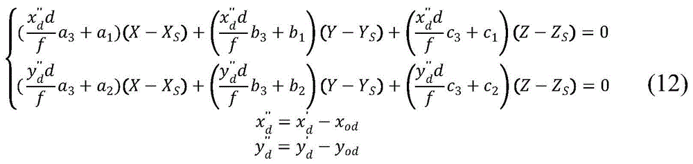
the equation of equation 12 above is a system of equations three-dimensional equations with X, Y, Z, the geometric meaning of which is the intersection of two planes. Reflecting the straight line where the corresponding image point, the shooting point and the object point are located. The geometric meaning of a single equation is a plane equation system with x or y as a parameter, and the equation system is an over-fixed point S. When all image points on the image plane are on a straight line, as l'1As objects, all that are described are in the same plane P1And two intersecting straight lines define a plane, and thus are like straight line l'1The coordinates (x ″) of the two reduced pixel points in the image plane are arbitrarily taken1d,y″1d)、(x″2d,y″2d) To determine the plane P1Normal vector (direction vector of normal vector perpendicular to the two straight lines). The calculation method is shown in formula 13.
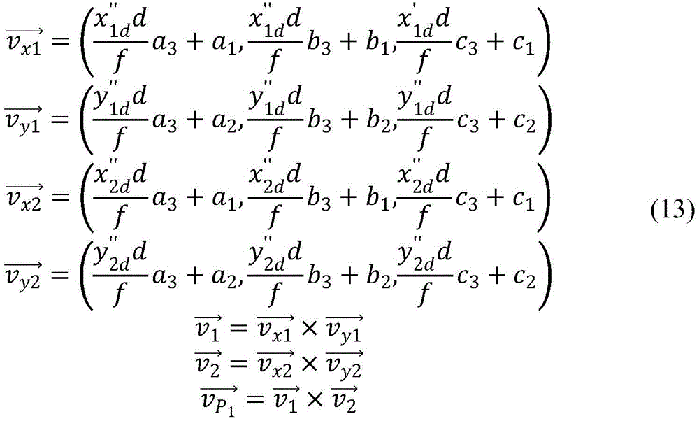
Wherein, and
and respectively, normal vectors of the planes represented by the corresponding equation families,
 are respectively pixel points (x ″)1d,y″1d)、(x″2d,y″2d) And the straight line of the photographing point.
 Is a plane P on which the two straight lines are located1The normal vector of (2). In the same way, the plane P can be obtained2Normal vector of (1)
 In addition, a plane P must be ensured1、P2Are oriented in a consistent manner. If not, the normal measurement of any plane is reversed.
Due to the plane P1、P2Is symmetrical about plane P, and1、l2parallel to each other, the normal vector of plane P is:
the normal vectors of the symmetry plane P, P' are determined from the data of the two image recording points. Because of the uniqueness of the cylindrical axis, the intersection line of the two symmetrical planes P, P' is the cylindrical axis, the direction of the cylindrical axis is solved, and the calculation mode is as follows:

based on the above principle, referring to fig. 5, the method for extracting the axis of the conductive arm of the high-voltage disconnecting switch provided by the embodiment includes the following steps:
step 1, collecting and processing complete image data of a conductive arm of a high-voltage isolating switch;
step 2, calculating an image edge linear equation of the conductive arm of the high-voltage isolating switch;
step 3, calculating a normal vector of the light tangent plane;
and 4, determining the axial direction of the conductive arm by intersecting the symmetry planes.
Wherein, step 1 specifically includes:
step 1.1, selecting feature points, selecting 3 or more than 3 suitable feature points on or near a high-voltage isolating switch conductive arm as homonymy points, wherein the homonymy points are image points of the same point on different images, selecting easily-identified and accurately-positioned points such as corner points and the like as the feature points by taking a high-voltage isolating switch design drawing as reference, and requiring the relative positions of the feature points on the high-voltage isolating switch to be determined;
step 1.2, selecting a shooting position, selecting a proper shooting point near the high-voltage isolating switch equipment to shoot complete image data of the high-voltage isolating switch conductive arm, wherein the conductive arm is required to be not shielded and comprises the selected characteristic point;
step 1.3, multiple operations are carried out, the high-voltage isolating switch conducting arm is shot at other angles and positions, the shooting requirement is the same as that of step 1.2, at least two groups of image data are needed for the same conducting arm, and data of more than two groups can be subjected to adjustment processing, so that errors are reduced;
step 1.4, image edge detection is carried out, the image is converted into a gray image, the gray image is processed by using a canny edge detection algorithm, and edge data of the shot image is obtained through steps of smoothing filtering, gradient calculation, non-maximum value inhibition, edge detection and the like;
and step 1.5, screening the edge image, removing the edge irrelevant to the conductive arm and the characteristic point from the image, and respectively reserving the edge image of the conductive arm and the edge image of the characteristic point.
Wherein, step 2 specifically includes:
step 2.1, converting a coordinate system, namely converting a pixel coordinate system of the digital image into an image plane coordinate system;
step 2.2, resolving exterior orientation elements, and resolving exterior orientation elements of corresponding images by a pyramid method according to the position information of the characteristic points, wherein the exterior orientation elements comprise exterior orientation line elements and exterior orientation angle elements of the images;
2.3, separating the outlines, namely separating according to the edge images of the conductive arm and respectively calculating linear equations of the contour lines on the two sides of the conductive arm;
and 2.4, calculating a linear equation of the edge of the conductive arm, and respectively fitting the linear equation of the edge image of the conductive arm by using the coordinate values of the pixel points in the image as objects and utilizing a least square method.
Wherein, step 3 specifically includes:
step 3.1, performing reduction on pixel points of the edge image of the conductive arm, specifically substituting the fitted linear equation and the pixel coordinate value of the image into formula (10) according to the fitted linear equation and the pixel coordinate value of the image, and performing reduction on the pixel point coordinates of the edge line to obtain new pixel point coordinates of the edge line;
step 3.2, calculating normal vectors of the light ray tangent planes, taking an edge straight line of the conductive arm as an object, randomly taking two pixel point coordinates after calculation on the straight line, and calculating two light ray tangent planes P1、P2The normal vector of (2) is specifically substituted for formula (13) to calculate two ray tangent planes P1、P2The normal vector of (a);
step 3.3, the normal vector directions of the light ray tangent planes are uniform, and the orientations of the light ray tangent planes are compared by P1、P2The orientation of any one of the planes is taken as a reference, and if the orientation of the other plane is opposite to that of the reference plane, the normal amount of the plane is taken in the opposite direction.
Wherein, step 4 specifically includes:
step 4.1, calculating a normal vector of the symmetry plane, taking the two light tangent plane normal vectors obtained in the step 3 as data, calculating a normal vector of the symmetry plane P where the axis of the conductive arm and the shooting point are located, and specifically calculating the normal vector of the symmetry plane P where the axis of the conductive arm and the shooting point are located according to the formula (14);
step 4.2, calculating another set of normal vectors of the symmetry plane, re-taking another set of data, repeating the step 1, the step 2 and the step 3, and correspondingly obtaining the normal vectors of the symmetry plane where the axes of the set of conductive arms and the shooting point are located;
and 4.3, calculating the axial vector of the conductive arm according to the principle that the intersection line of the two planes is perpendicular to the normal vectors of the two planes respectively and according to the symmetrical plane normal vector obtained in the step 4.1 and the step 4.2, and specifically, substituting the symmetrical plane normal vector obtained in the step 4.1 and the step 4.2 into a formula (15) for calculating the axial vector of the conductive arm to finish the axial extraction of the conductive arm.
In summary, according to the method for extracting the axis of the conductive arm of the high-voltage disconnecting switch provided by the invention, by taking close-range photogrammetry and image recognition technology as means, the automatic extraction of the axis of the conductive arm of the high-voltage disconnecting switch is realized, and the method can be used as an effective detection tool for a rapid detection technology of the closing state of the high-voltage disconnecting switch, and has the following effective effects:
1) by constructing a physical model for shooting the conductive arm, the mathematical relationship among a light tangent plane normal vector, a symmetric plane normal vector and a conductive arm axial direction vector is analyzed, a mode of calculating the symmetric plane normal vector in a mode of synthesizing the two light tangent plane normal vectors is provided, and a mode of extracting the cylindrical axis of the conductive arm is further extracted by a vector product between two different symmetric plane normal vectors;
2) by taking close-range photogrammetry, image recognition and edge detection as means, pixel point coordinates of an edge image are obtained by calculating a linear equation of the edge of a conductive arm in the image, a normal vector of a light tangent plane is determined, and a virtual light tangent plane normal vector calculation problem is converted into a real image pixel point coordinate problem;
3) the method for extracting the characteristic points on the basis of the self structure of the high-voltage isolating switch is provided, so that the difficulty caused by adding marks on the electrified equipment is avoided;
4) the problem of coordinate step property of the pixel point of the digital image is solved by using a least square method, and the precision is improved.
In the description herein, references to the description of the term "one embodiment," "some embodiments," "an example," "a specific example," or "some examples," etc., mean that a particular feature, structure, material, or characteristic described in connection with the embodiment or example is included in at least one embodiment or example of the invention. In this specification, the schematic representations of the terms used above do not necessarily refer to the same embodiment or example. Furthermore, the particular features, structures, materials, or characteristics described may be combined in any suitable manner in any one or more embodiments or examples.
While embodiments of the invention have been shown and described, it will be understood by those of ordinary skill in the art that: various changes, modifications, substitutions and alterations can be made to the embodiments without departing from the principles and spirit of the invention, the scope of which is defined by the claims and their equivalents.
Claims (5)
1. A method for extracting an axis of a conductive arm of a high-voltage isolating switch is characterized by comprising the following steps:
step 1, collecting and processing complete image data of a conductive arm of a high-voltage isolating switch;
step 2, calculating an image edge linear equation of the conductive arm of the high-voltage isolating switch;
step 3, calculating a normal vector of the light tangent plane;
and 4, determining the axial direction of the conductive arm by intersecting the symmetry planes.
2. The method for extracting the axis of the conducting arm of the high-voltage isolating switch as claimed in claim 1, wherein the step 1 specifically comprises:
step 1.1, selecting feature points, selecting 3 or more than 3 suitable feature points on or near a conductive arm of a high-voltage isolating switch as homonymy points, wherein the homonymy points are image points of the same point on different images of an object, selecting points which are easy to identify and accurate to position as the feature points by taking a design drawing of the high-voltage isolating switch as reference, and requiring the relative position of the feature points on the high-voltage isolating switch to be determined;
step 1.2, selecting a shooting position, selecting a proper shooting point near the high-voltage isolating switch equipment to shoot complete image data of the high-voltage isolating switch conductive arm, wherein the conductive arm is required to be not shielded and comprises the selected characteristic point;
step 1.3, multiple operations are carried out, the high-voltage isolating switch conducting arm is shot at other angles and positions, the shooting requirement is the same as that of step 1.2, at least two groups of image data are needed for the same conducting arm, and data of more than two groups can be subjected to adjustment processing, so that errors are reduced;
step 1.4, image edge detection is carried out, the image is converted into a gray image, the gray image is processed by using a canny edge detection algorithm, and edge data of the shot image is obtained through the steps of smooth filtering, gradient calculation, non-maximum value inhibition and edge detection;
and step 1.5, screening the edge image, removing the edge irrelevant to the conductive arm and the characteristic point from the image, and respectively reserving the edge image of the conductive arm and the edge image of the characteristic point.
3. The method for extracting the axis of the conducting arm of the high-voltage isolating switch as claimed in claim 2, wherein the step 2 specifically comprises:
step 2.1, converting a coordinate system, namely converting a pixel coordinate system of the digital image into an image plane coordinate system;
step 2.2, resolving exterior orientation elements, and resolving exterior orientation elements of corresponding images by a pyramid method according to the position information of the characteristic points, wherein the exterior orientation elements comprise exterior orientation line elements and exterior orientation angle elements of the images;
2.3, separating the outlines, namely separating according to the edge images of the conductive arm and respectively calculating linear equations of the contour lines on the two sides of the conductive arm;
and 2.4, calculating a linear equation of the edge of the conductive arm, and respectively fitting the linear equation of the edge image of the conductive arm by using the coordinate values of the pixel points in the image as objects and utilizing a least square method.
4. The method for extracting the axis of the conducting arm of the high-voltage isolating switch as claimed in claim 3, wherein the step 3 specifically comprises:
step 3.1, performing reduction on pixel points of the edge image of the conductive arm, and performing reduction on pixel point coordinates of the edge line according to the fitted linear equation and the pixel coordinate value of the image to obtain new pixel point coordinates of the edge line;
step 3.2, calculating normal vectors of the light ray tangent planes, taking an edge straight line of the conductive arm as an object, randomly taking two pixel point coordinates after calculation on the straight line, and calculating two light ray tangent planes P1、P2The normal vector of (a);
step 3.3, the normal vector directions of the light ray tangent planes are uniform, and the orientations of the light ray tangent planes are compared by P1、P2The orientation of any one of the planes is taken as a reference, and if the orientation of the other plane is opposite to that of the reference plane, the normal amount of the plane is taken in the opposite direction.
5. The method for extracting the axis of the conducting arm of the high-voltage isolating switch as claimed in claim 4, wherein the step 4 specifically comprises:
step 4.1, calculating a normal vector of the symmetry plane, and calculating a normal vector of the symmetry plane P where the axis of the conductive arm and the shooting point are located by taking the two light tangent plane normal vectors obtained in the step 3 as data;
step 4.2, calculating another set of normal vectors of the symmetry plane, re-taking another set of data, repeating the step 1, the step 2 and the step 3, and correspondingly obtaining the normal vectors of the symmetry plane where the axes of the set of conductive arms and the shooting point are located;
and 4.3, calculating the axial direction vector of the conductive arm, and according to the principle that the intersection line of the two planes is perpendicular to the normal vectors of the two planes respectively and the normal vectors of the symmetrical planes obtained in the steps 4.1 and 4.2, calculating the axial direction vector of the conductive arm to finish the axial extraction of the conductive arm.
Priority Applications (1)
| Application Number | Priority Date | Filing Date | Title |
|---|---|---|---|
| CN202010510134.3A CN111798476B (en) | 2020-06-08 | 2020-06-08 | A method for extracting the axis of the conductive arm of a high-voltage isolation switch |
Applications Claiming Priority (1)
| Application Number | Priority Date | Filing Date | Title |
|---|---|---|---|
| CN202010510134.3A CN111798476B (en) | 2020-06-08 | 2020-06-08 | A method for extracting the axis of the conductive arm of a high-voltage isolation switch |
Publications (2)
| Publication Number | Publication Date |
|---|---|
| CN111798476A true CN111798476A (en) | 2020-10-20 |
| CN111798476B CN111798476B (en) | 2023-10-20 |
Family
ID=72804230
Family Applications (1)
| Application Number | Title | Priority Date | Filing Date |
|---|---|---|---|
| CN202010510134.3A Active CN111798476B (en) | 2020-06-08 | 2020-06-08 | A method for extracting the axis of the conductive arm of a high-voltage isolation switch |
Country Status (1)
| Country | Link |
|---|---|
| CN (1) | CN111798476B (en) |
Cited By (2)
| Publication number | Priority date | Publication date | Assignee | Title |
|---|---|---|---|---|
| CN114743825A (en) * | 2022-06-09 | 2022-07-12 | 武汉黉门电工科技有限公司 | Isolating switch and method for monitoring on-off state of isolating switch |
| CN119515928A (en) * | 2024-09-29 | 2025-02-25 | 南京师范大学 | A high-precision planar homography calculation method for urban surveillance videos |
Citations (21)
| Publication number | Priority date | Publication date | Assignee | Title |
|---|---|---|---|---|
| US20040233461A1 (en) * | 1999-11-12 | 2004-11-25 | Armstrong Brian S. | Methods and apparatus for measuring orientation and distance |
| WO2008034942A1 (en) * | 2006-09-22 | 2008-03-27 | Teknillinen Korkeakoulu | Method and apparatus for stereopanoramic imaging |
| JP2011070579A (en) * | 2009-09-28 | 2011-04-07 | Dainippon Printing Co Ltd | Captured image display device |
| US8472015B1 (en) * | 2010-12-07 | 2013-06-25 | Trimble Navigation Ltd | Fan beam resection using direct linear transform and singular value decomposition |
| CN103344396A (en) * | 2013-07-16 | 2013-10-09 | 吉林大学 | System and method for measuring bridge deflection based on close-range photographic measurement |
| CN103558619A (en) * | 2013-11-06 | 2014-02-05 | 中测新图(北京)遥感技术有限责任公司 | Method for obtaining exterior orientation elements of aerial photograph |
| CN203491172U (en) * | 2013-10-12 | 2014-03-19 | 无锡恒驰电器制造有限公司 | Conductive arm structure of high voltage disconnector |
| CN104567666A (en) * | 2013-10-28 | 2015-04-29 | 上海金艺检测技术有限公司 | Measuring method for roller bearing block spatial position |
| CN105205808A (en) * | 2015-08-20 | 2015-12-30 | 武汉大学 | Multi-vision image dense coupling fusion method and system based on multiple characteristics and multiple constraints |
| CN106446343A (en) * | 2016-07-25 | 2017-02-22 | 北京航空航天大学 | Method for automatically extracting parameterized profile line of straight-line blade of radial-flow impeller |
| CN107218928A (en) * | 2017-05-12 | 2017-09-29 | 西北工业大学 | A kind of complicated multi- piping branch system detection method |
| CN107316330A (en) * | 2017-06-13 | 2017-11-03 | 西安科技大学 | Underground hydraulic support frame group pose and verticality measuring method based on many image sequences |
| CN107644119A (en) * | 2017-08-15 | 2018-01-30 | 四川大学 | A kind of Half cast factor automatic calculating method based on 3-D scanning point cloud |
| CN108008259A (en) * | 2017-11-14 | 2018-05-08 | 国网江西省电力有限公司电力科学研究院 | Based on infrared, the integrated detection method of Uv and visible light image co-registration and device |
| CN108458665A (en) * | 2018-02-11 | 2018-08-28 | 中铁八局集团第二工程有限公司 | The method for carrying out the quick distortion measurement in tunnel using up short |
| CN109272574A (en) * | 2018-09-10 | 2019-01-25 | 武汉大学 | Method and calibration method for imaging model of linear array rotating scanning camera based on projection transformation |
| CN109470149A (en) * | 2018-12-12 | 2019-03-15 | 北京理工大学 | A method and device for measuring the pose of a pipeline |
| CN110108203A (en) * | 2019-04-11 | 2019-08-09 | 东莞中子科学中心 | Silk thread position measuring method and system based on photogrammetry technology |
| CN110388898A (en) * | 2019-06-27 | 2019-10-29 | 中国科学院遥感与数字地球研究所 | Constructing a multi-source multi-coverage remote sensing image adjustment method constrained by virtual control points |
| CN111563335A (en) * | 2020-07-01 | 2020-08-21 | 国网江西省电力有限公司电力科学研究院 | Laser radar-based high-voltage isolating switch closing state detection method |
| CN114777668A (en) * | 2022-04-12 | 2022-07-22 | 新拓三维技术(深圳)有限公司 | Desktop type elbow measuring method and device |
-
2020
- 2020-06-08 CN CN202010510134.3A patent/CN111798476B/en active Active
Patent Citations (21)
| Publication number | Priority date | Publication date | Assignee | Title |
|---|---|---|---|---|
| US20040233461A1 (en) * | 1999-11-12 | 2004-11-25 | Armstrong Brian S. | Methods and apparatus for measuring orientation and distance |
| WO2008034942A1 (en) * | 2006-09-22 | 2008-03-27 | Teknillinen Korkeakoulu | Method and apparatus for stereopanoramic imaging |
| JP2011070579A (en) * | 2009-09-28 | 2011-04-07 | Dainippon Printing Co Ltd | Captured image display device |
| US8472015B1 (en) * | 2010-12-07 | 2013-06-25 | Trimble Navigation Ltd | Fan beam resection using direct linear transform and singular value decomposition |
| CN103344396A (en) * | 2013-07-16 | 2013-10-09 | 吉林大学 | System and method for measuring bridge deflection based on close-range photographic measurement |
| CN203491172U (en) * | 2013-10-12 | 2014-03-19 | 无锡恒驰电器制造有限公司 | Conductive arm structure of high voltage disconnector |
| CN104567666A (en) * | 2013-10-28 | 2015-04-29 | 上海金艺检测技术有限公司 | Measuring method for roller bearing block spatial position |
| CN103558619A (en) * | 2013-11-06 | 2014-02-05 | 中测新图(北京)遥感技术有限责任公司 | Method for obtaining exterior orientation elements of aerial photograph |
| CN105205808A (en) * | 2015-08-20 | 2015-12-30 | 武汉大学 | Multi-vision image dense coupling fusion method and system based on multiple characteristics and multiple constraints |
| CN106446343A (en) * | 2016-07-25 | 2017-02-22 | 北京航空航天大学 | Method for automatically extracting parameterized profile line of straight-line blade of radial-flow impeller |
| CN107218928A (en) * | 2017-05-12 | 2017-09-29 | 西北工业大学 | A kind of complicated multi- piping branch system detection method |
| CN107316330A (en) * | 2017-06-13 | 2017-11-03 | 西安科技大学 | Underground hydraulic support frame group pose and verticality measuring method based on many image sequences |
| CN107644119A (en) * | 2017-08-15 | 2018-01-30 | 四川大学 | A kind of Half cast factor automatic calculating method based on 3-D scanning point cloud |
| CN108008259A (en) * | 2017-11-14 | 2018-05-08 | 国网江西省电力有限公司电力科学研究院 | Based on infrared, the integrated detection method of Uv and visible light image co-registration and device |
| CN108458665A (en) * | 2018-02-11 | 2018-08-28 | 中铁八局集团第二工程有限公司 | The method for carrying out the quick distortion measurement in tunnel using up short |
| CN109272574A (en) * | 2018-09-10 | 2019-01-25 | 武汉大学 | Method and calibration method for imaging model of linear array rotating scanning camera based on projection transformation |
| CN109470149A (en) * | 2018-12-12 | 2019-03-15 | 北京理工大学 | A method and device for measuring the pose of a pipeline |
| CN110108203A (en) * | 2019-04-11 | 2019-08-09 | 东莞中子科学中心 | Silk thread position measuring method and system based on photogrammetry technology |
| CN110388898A (en) * | 2019-06-27 | 2019-10-29 | 中国科学院遥感与数字地球研究所 | Constructing a multi-source multi-coverage remote sensing image adjustment method constrained by virtual control points |
| CN111563335A (en) * | 2020-07-01 | 2020-08-21 | 国网江西省电力有限公司电力科学研究院 | Laser radar-based high-voltage isolating switch closing state detection method |
| CN114777668A (en) * | 2022-04-12 | 2022-07-22 | 新拓三维技术(深圳)有限公司 | Desktop type elbow measuring method and device |
Non-Patent Citations (5)
| Title |
|---|
| HOSSAM EL-DIN FAWZY: "THE ACCURACY OF MOBILE PHONE CAMERA INSTEAD OF HIGH RESOLUTION CAMERA IN DIGITAL CLOSE RANGE PHOTOGRAMMETRY", 《INTERNATIONAL JOURNAL OF CIVIL ENGINEERING AND TECHNOLOGY(IJCIET)》, pages 76 - 85 * |
| 冯其强: "数字工业摄影测量中的标志点匹配和自检校光束法平差快速解算", 《中国优秀硕士学位论文全文数据库 基础科学辑》, pages 008 - 35 * |
| 杨松勇: "近景摄影测量技术在露天矿边坡变形监测中的研究", 《中国优秀硕士学位论文全文数据库 基础科学辑》, pages 008 - 387 * |
| 续玉倩: "数字近景摄影测量在钢桁架节点试验中的研究与应用", 《中国优秀硕士学位论文全文数据库 工程科技II辑》, pages 038 - 2067 * |
| 马开锋: "高低温环境卫星天线形面变形的近景摄影测量与数据处理", 《中国博士学位论文全文数据库 基础科学辑》, pages 008 - 22 * |
Cited By (2)
| Publication number | Priority date | Publication date | Assignee | Title |
|---|---|---|---|---|
| CN114743825A (en) * | 2022-06-09 | 2022-07-12 | 武汉黉门电工科技有限公司 | Isolating switch and method for monitoring on-off state of isolating switch |
| CN119515928A (en) * | 2024-09-29 | 2025-02-25 | 南京师范大学 | A high-precision planar homography calculation method for urban surveillance videos |
Also Published As
| Publication number | Publication date |
|---|---|
| CN111798476B (en) | 2023-10-20 |
Similar Documents
| Publication | Publication Date | Title |
|---|---|---|
| CN109615611B (en) | A detection method for self-explosion defects of insulators based on inspection images | |
| CN106257535B (en) | Electrical equipment based on SURF operator is infrared and visible light image registration method | |
| Bourdis et al. | Constrained optical flow for aerial image change detection | |
| CN102175222B (en) | Crane obstacle-avoidance system based on stereoscopic vision | |
| CN107169401B (en) | Track Intrusion Detection Method Based on Track Visual Feature Spectrum | |
| Lee et al. | Automatic integration of facade textures into 3D building models with a projective geometry based line clustering | |
| CN104484648A (en) | Variable-viewing angle obstacle detection method for robot based on outline recognition | |
| CN109801291B (en) | A method for acquiring multi-surface three-dimensional topography of moving abrasive particles | |
| CN115294145B (en) | Method and system for measuring sag of power transmission line | |
| CN111798476A (en) | A method for extracting the axis of the conductive arm of a high-voltage isolation switch | |
| CN114937203B (en) | Foreign object detection method for airport runway based on multi-view image parallax | |
| CN116051876A (en) | Camera array target recognition method and system for 3D digital model | |
| CN119888077A (en) | Three-dimensional structure reconstruction method and system for dry type transformer | |
| Wang | Automatic extraction of building outline from high resolution aerial imagery | |
| Ouyang et al. | From pixel to infrastructure: Photogrammetry-based tunnel crack digitalization and documentation method using deep learning | |
| CN117314986A (en) | UAV cross-modal power distribution equipment inspection image registration method based on semantic segmentation | |
| CN113836975A (en) | Obstacle avoidance method for UAV with binocular vision based on YOLOV3 | |
| Kutulakos | Shape from the light field boundary | |
| Xu et al. | Monocular video frame optimization through feature-based parallax analysis for 3D pipe reconstruction | |
| CN119476963A (en) | Power operation safety risk identification method and system based on fine-grained detection | |
| CN119205875A (en) | A parameter measurement method for large-size lightning arresters based on robotic arm collaborative 3D reconstruction | |
| CN110992291A (en) | Ranging method, system and storage medium based on trinocular vision | |
| Benz et al. | Mvcrackvit: Robust multi-view crack detection for point cloud segmentation using view attention | |
| Niblock et al. | Fast model-based feature matching technique applied to airport lighting | |
| CN117132789B (en) | Method and device for identifying opening and closing states of opening and closing members and storage medium |
Legal Events
| Date | Code | Title | Description |
|---|---|---|---|
| PB01 | Publication | ||
| PB01 | Publication | ||
| SE01 | Entry into force of request for substantive examination | ||
| SE01 | Entry into force of request for substantive examination | ||
| GR01 | Patent grant | ||
| GR01 | Patent grant |