CN111789634B - A path planning method for automatic ultrasound scanning of human spine - Google Patents
A path planning method for automatic ultrasound scanning of human spine Download PDFInfo
- Publication number
- CN111789634B CN111789634B CN202010517767.7A CN202010517767A CN111789634B CN 111789634 B CN111789634 B CN 111789634B CN 202010517767 A CN202010517767 A CN 202010517767A CN 111789634 B CN111789634 B CN 111789634B
- Authority
- CN
- China
- Prior art keywords
- curve
- point
- polynomial
- path
- dimensional
- Prior art date
- Legal status (The legal status is an assumption and is not a legal conclusion. Google has not performed a legal analysis and makes no representation as to the accuracy of the status listed.)
- Active
Links
Images


Classifications
-
- G—PHYSICS
- G06—COMPUTING OR CALCULATING; COUNTING
- G06T—IMAGE DATA PROCESSING OR GENERATION, IN GENERAL
- G06T17/00—Three dimensional [3D] modelling, e.g. data description of 3D objects
-
- A—HUMAN NECESSITIES
- A61—MEDICAL OR VETERINARY SCIENCE; HYGIENE
- A61B—DIAGNOSIS; SURGERY; IDENTIFICATION
- A61B34/00—Computer-aided surgery; Manipulators or robots specially adapted for use in surgery
- A61B34/10—Computer-aided planning, simulation or modelling of surgical operations
-
- A—HUMAN NECESSITIES
- A61—MEDICAL OR VETERINARY SCIENCE; HYGIENE
- A61B—DIAGNOSIS; SURGERY; IDENTIFICATION
- A61B8/00—Diagnosis using ultrasonic, sonic or infrasonic waves
- A61B8/54—Control of the diagnostic device
-
- A—HUMAN NECESSITIES
- A61—MEDICAL OR VETERINARY SCIENCE; HYGIENE
- A61B—DIAGNOSIS; SURGERY; IDENTIFICATION
- A61B34/00—Computer-aided surgery; Manipulators or robots specially adapted for use in surgery
- A61B34/10—Computer-aided planning, simulation or modelling of surgical operations
- A61B2034/107—Visualisation of planned trajectories or target regions
Landscapes
- Health & Medical Sciences (AREA)
- Life Sciences & Earth Sciences (AREA)
- Engineering & Computer Science (AREA)
- Physics & Mathematics (AREA)
- Surgery (AREA)
- Public Health (AREA)
- Nuclear Medicine, Radiotherapy & Molecular Imaging (AREA)
- Heart & Thoracic Surgery (AREA)
- Medical Informatics (AREA)
- Molecular Biology (AREA)
- Animal Behavior & Ethology (AREA)
- General Health & Medical Sciences (AREA)
- Biomedical Technology (AREA)
- Veterinary Medicine (AREA)
- Robotics (AREA)
- Computer Graphics (AREA)
- Geometry (AREA)
- Software Systems (AREA)
- General Physics & Mathematics (AREA)
- Theoretical Computer Science (AREA)
- Biophysics (AREA)
- Pathology (AREA)
- Radiology & Medical Imaging (AREA)
- Image Processing (AREA)
Abstract
本发明公开了一种人体脊柱自动化超声扫查的路径规划方法,该方法采用深度相机获取人体背部区域的彩色图与深度图,重建出人体背部三维点云模型,并进行平滑处理。在彩色图上绘制超声扫查轨迹,并将其投影到三维点云模型,从而获得一组三维空间坐标点。将这一组三维坐标点分段,每段采用五次及以上多项式拟合,以每两段交点处的位置、速度、加速度作为边界条件,以近似曲线在实际坐标点处的偏差的平方和作为代价函数,将其转换为二次规划问题,求解各段多项式的参数,从而得到一条光滑的人体脊柱扫查曲线。本发明方法可较为快速的获得较高质量的脊柱扫查曲线,从而指导人体脊柱的自动化超声扫查。

The invention discloses a path planning method for automatic ultrasonic scanning of the human spine. The method adopts a depth camera to obtain a color map and a depth map of the back region of the human body, reconstructs a three-dimensional point cloud model of the back of the human body, and performs smoothing processing. The ultrasound scan trajectory is drawn on the color map and projected to the 3D point cloud model to obtain a set of 3D space coordinate points. This group of three-dimensional coordinate points is divided into segments, each segment is fitted with a polynomial of the fifth degree or more, and the position, velocity, and acceleration at the intersection of each two segments are used as boundary conditions to approximate the sum of the squares of the deviations of the curve at the actual coordinate points. As a cost function, it is transformed into a quadratic programming problem, and the parameters of each segment of the polynomial are solved to obtain a smooth human spine scan curve. The method of the invention can obtain a relatively high-quality spine scanning curve relatively quickly, so as to guide the automatic ultrasonic scanning of the human spine.
Description
技术领域technical field
本发明涉及到医学超声扫查领域,尤其是机器人辅助的人体脊柱超声扫查,具体涉及一种人体脊柱自动化超声扫查的路径规划方法。The invention relates to the field of medical ultrasound scanning, in particular to robot-assisted human spine ultrasound scanning, and in particular to a path planning method for automatic human spine ultrasound scanning.
背景技术Background technique
脊柱已经成为人类的第二大常见病,约60-80%的人在一生中会受到脊柱疾病的困扰,其中约10-20%可能需要手术干预。目前,微创手术已成为脊柱疾病主流手术治疗方式,其较高的技术门槛需要辅助诊疗设备与技术支持,因此导航技术在脊柱脊髓相关疾病的手术过程中发挥出越发重要的作用。医学超声由于其具有无辐射性,在软组织及脏器导航中的作用日益显著,业界也在不断探究其用于脊柱脊髓手术导航的可行性与实用性。The spine has become the second most common disease in humans, about 60-80% of people will suffer from spinal diseases in their lifetime, and about 10-20% of them may require surgical intervention. At present, minimally invasive surgery has become the mainstream surgical treatment for spinal diseases, and its high technical threshold requires auxiliary diagnosis and treatment equipment and technical support. Therefore, navigation technology plays an increasingly important role in the surgical process of spinal cord-related diseases. Because of its non-radiation, medical ultrasound plays an increasingly significant role in soft tissue and organ navigation, and the industry is constantly exploring its feasibility and practicability for spinal cord surgery navigation.
聚焦于机器人辅助医学超声扫查领域,为实现人体脊柱的自动化超声扫查过程,需要规划出贴合人体脊柱曲线的路径。然而,目前现有的方法大多聚焦于脊柱中线的提取,常见的处理方法包括莫尔(Moire)图像测量法、X光片测量法、结构光测量法、激光扫描仪测量法等。其估计的人体脊柱曲线缺乏深度信息,故而存在较大偏差。虽然也有针对三维点云的脊柱中线提取方案,但是其主要针对的是脊柱侧弯场景,利用脊柱两侧点云是否对称判断脊柱侧弯程度。Focusing on the field of robot-assisted medical ultrasound scanning, in order to realize the automatic ultrasound scanning process of the human spine, it is necessary to plan a path that fits the curve of the human spine. However, most of the existing methods focus on the extraction of the midline of the spine. Common processing methods include Moire image measurement, X-ray measurement, structured light measurement, and laser scanner measurement. The estimated human spine curve lacks depth information, so there is a large deviation. Although there are also spine midline extraction solutions for 3D point clouds, they are mainly aimed at scoliosis scenarios, and the degree of scoliosis is judged by whether the point clouds on both sides of the spine are symmetrical.
发明内容SUMMARY OF THE INVENTION
本发明的发明目的是:为了解决现有技术中存在的以上问题,本发明提出了一种人体脊柱自动化超声扫查的路径规划方法。The purpose of the present invention is: in order to solve the above problems existing in the prior art, the present invention proposes a path planning method for automatic ultrasonic scanning of human spine.
本发明的技术方案是:一种人体脊柱自动化超声扫查的路径规划方法,包括以下步骤:The technical scheme of the present invention is: a path planning method for automatic ultrasound scanning of human spine, comprising the following steps:
A、采用深度相机获取人体背部区域的彩色图与深度图,重建出人体背部三维点云模型,并进行平滑处理;A. Use the depth camera to obtain the color map and depth map of the back area of the human body, reconstruct the 3D point cloud model of the back of the human body, and perform smooth processing;
B、在彩色图绘制人体脊柱的超声扫查轨迹,将该轨迹上的二维像素坐标点投影到三维点云模型,从而获得轨迹的三维空间坐标点;B. Draw the ultrasound scanning trajectory of the human spine on the color map, and project the two-dimensional pixel coordinate points on the trajectory to the three-dimensional point cloud model, thereby obtaining the three-dimensional space coordinate points of the trajectory;
C、将步骤B中的得到三维空间坐标点进行分段,每段采用五次及以上多项式拟合,以每两段交点处的位置、速度、加速度对应相等作为边界条件,以近似曲线在实际坐标点处的偏差的平方和作为代价函数,转换为二次规划问题,求解各段多项式的参数,从而得到一条光滑的人体脊柱扫查曲线。C. Segment the three-dimensional space coordinate points obtained in step B, each segment is fitted with a polynomial of the fifth degree or more, and the position, velocity, and acceleration at the intersection of each two segments are correspondingly equal as boundary conditions, and the approximate curve is used in the actual The squared sum of the deviations at the coordinate points is used as a cost function, which is converted into a quadratic programming problem, and the parameters of each segment of the polynomial are solved to obtain a smooth human spine scan curve.
进一步地,步骤A具体包括如下步骤:Further, step A specifically includes the following steps:
A1、采用深度相机获取同一时刻人体背部区域的彩色图与深度图;A1. Use the depth camera to obtain the color map and depth map of the back area of the human body at the same time;
A2、利用步骤A1得到的彩色图与深度图以及深度相机的内参信息重建人体背部三维点云模型;A2. Use the color map and depth map obtained in step A1 and the internal reference information of the depth camera to reconstruct the three-dimensional point cloud model of the back of the human body;
A3、可以采用双边滤波算法对步骤A2得到的三维点云模型进行平滑处理。A3. A bilateral filtering algorithm can be used to smooth the three-dimensional point cloud model obtained in step A2.
进一步地,步骤B具体包括如下步骤:Further, step B specifically includes the following steps:
B1、使用OpenGL的画笔工具手动在彩色图人体背部区域绘制人体脊柱的超声扫查轨迹;B1. Use the brush tool of OpenGL to manually draw the ultrasound scan trajectory of the human spine in the back area of the human body in the color map;
B2、利用深度相机内参信息,将超声扫查轨迹上的二维像素坐标点投影到三维点云模型,从而获得轨迹的三维空间坐标点,可以与重建人体背部三维点云模型过程一致。B2. Using the internal parameter information of the depth camera, project the two-dimensional pixel coordinate points on the ultrasonic scanning trajectory to the three-dimensional point cloud model, so as to obtain the three-dimensional space coordinate points of the trajectory, which can be consistent with the process of reconstructing the three-dimensional point cloud model of the back of the human body.
进一步地,步骤C具体包括如下步骤:Further, step C specifically includes the following steps:
C1、将步骤B中得到的轨迹的三维空间坐标点按照每五点为一组的形式分段;C1, the three-dimensional space coordinate points of the trajectory obtained in step B are segmented according to the form that every five points are a group;
C2、每段采用五次及以上多项式拟合,并以两段交点处的位置、速度、加速度对应相等作为边界条件;C2. Each segment is fitted with a fifth degree or more polynomial, and the position, velocity, and acceleration at the intersection of the two segments are correspondingly equal as the boundary conditions;
C3、以近似曲线在实际坐标点处的偏差的平方和作为代价函数,以步骤C2中的边界条件作为约束项,转换为具有等式约束条件的二次规划问题,使用二次规划求解器求解多项式的参数。C3. Use the squared sum of the deviation of the approximate curve at the actual coordinate point as the cost function, and use the boundary conditions in step C2 as the constraint item, convert it into a quadratic programming problem with equality constraints, and use a quadratic programming solver to solve The parameters of the polynomial.
进一步地,步骤A2利用相机内参信息重建人体背部三维点云模型的公式具体为:Further, the formula for reconstructing the three-dimensional point cloud model of the back of the human body using the camera internal reference information in step A2 is as follows:

其中,μ,v是彩色图像坐标系下的坐标值,μ0,v0是深度相机的标定中心,f为理想的焦距值,d是深度图像上对应于μ,v坐标点的深度值,xw,yw,zw是三维点云空间下的三维坐标值。Among them, μ, v are the coordinate values in the color image coordinate system, μ 0 , v 0 are the calibration center of the depth camera, f is the ideal focal length value, d is the depth value corresponding to the μ, v coordinate point on the depth image, x w , y w , z w are the three-dimensional coordinate values in the three-dimensional point cloud space.
进一步地,步骤A3中采用双边滤波算法对三维点云进行平滑处理的公式具体为:Further, the formula for smoothing the three-dimensional point cloud using the bilateral filtering algorithm in step A3 is as follows:

其中,pi为滤波前的点的坐标,


进一步地,步骤C2中每段采用多项式拟合的公式具体为:Further, in step C2, the formula of each section using polynomial fitting is specifically:

其中,t为多项式的自变量,即每段上的点的横坐标,i为自变量的幂,li为多项式中对应于t第i次幂的系数,即为多项式拟合的参数,p(t)多项式的因变量,即每段上的点的纵坐标,m为多项式的阶次。Among them, t is the independent variable of the polynomial, that is, the abscissa of the point on each segment, i is the power of the independent variable, li is the coefficient corresponding to the i-th power of t in the polynomial, which is the parameter of the polynomial fitting, p (t) The dependent variable of the polynomial, that is, the ordinate of the point on each segment, and m is the order of the polynomial.
进一步地,步骤C2中以两段交点处的位置、速度、加速度对应相等作为边界条件的公式具体为:Further, in step C2, the formula of the position, velocity, and acceleration at the intersection of the two sections that are correspondingly equal as the boundary condition is specifically:


其中,


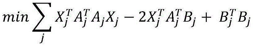
进一步地,步骤C3中以近似曲线在实际坐标点处的偏差的平方和作为代价函数的公式具体为:Further, in step C3, the formula of using the square sum of the deviation of the approximate curve at the actual coordinate point as the cost function is as follows:

采用矩阵形式,可表示为:In matrix form, it can be expressed as:


其中,ti表示拟合曲线所用到的路径点的横坐标,yi表示拟合曲线所用到的路径点的横坐标的纵坐标,Pj(ti)表示拟合的第j段曲线在ti处的值,Xj表示第j段曲线的参数li组成的列向量,Aj表示拟合第j段曲线所用到的每一个路径点的横坐标的第0次到第m次幂的值组成的矩阵,Bj表示拟合第j段曲线所用到的路径点的纵坐标,Lj表示第j段曲线的损失,L表示全段轨迹的损失和,j表示拟合的某一段多项式曲线的标号,

进一步地,步骤C3中以步骤C2中的边界条件作为约束项,将其转换为具有等式约束条件的二次规划问题的公式具体为:Further, in step C3, the boundary condition in step C2 is used as the constraint term, and the formula for converting it into a quadratic programming problem with equality constraints is as follows:

与现有技术相比,本发明的有益效果是:采用深度相机获取人体背部区域的彩色图与深度图,重建出人体背部三维点云模型,并进行平滑处理。在彩色图上绘制人体脊柱的超声扫查轨迹,并将其投影到三维点云模型,从而获得三维空间坐标点。将三维空间坐标点进行多段,每段采用五次及以上多项式拟合,以两段交点处的位置、速度、加速度约束对应相等作为边界条件,以近似曲线在实际坐标点处的偏差的平方和作为代价函数,将其转换为二次规划问题,求解各段多项式的参数,从而获得一条光滑的人体脊柱扫查曲线。该方法充分利用了深度相机所得到的深度信息,可较为快速的获得较高质量的扫描轨迹,从而指导人体脊柱的自动化超声扫查。Compared with the prior art, the present invention has the beneficial effects that the depth camera is used to obtain the color map and the depth map of the back region of the human body, and the three-dimensional point cloud model of the back of the human body is reconstructed and smoothed. The ultrasound scan trajectory of the human spine is drawn on the color map, and it is projected to the three-dimensional point cloud model to obtain three-dimensional space coordinate points. The three-dimensional space coordinate points are multi-segmented, and each segment is fitted with a polynomial of the fifth degree or more. The position, velocity, and acceleration constraints at the intersection of the two segments are correspondingly equal as the boundary conditions, and the square sum of the deviation of the approximate curve at the actual coordinate point is used. As a cost function, it is converted into a quadratic programming problem, and the parameters of each segment of the polynomial are solved to obtain a smooth human spine scan curve. The method makes full use of the depth information obtained by the depth camera, and can obtain a high-quality scanning trajectory relatively quickly, thereby guiding the automatic ultrasound scanning of the human spine.
附图说明Description of drawings
图1是本发明的一种用于人体脊柱自动化超声扫查的路径规划方法的程序流程图。FIG. 1 is a program flow chart of a path planning method for automatic ultrasound scanning of human spine according to the present invention.
图2是本发明实施例中采用深度相机获取的人体背部区域的三维点云的俯视图。FIG. 2 is a top view of a three-dimensional point cloud of a back region of a human body acquired by a depth camera in an embodiment of the present invention.
图3是本发明实施例中优化后得到的用于人体脊柱超声扫查的三维轨迹示意图,坐标单位为m。FIG. 3 is a schematic diagram of a three-dimensional trajectory for ultrasound scanning of the human spine obtained after optimization in an embodiment of the present invention, and the coordinate unit is m.
图4是本发明实施例中优化后得到的点云模型空间下的超声扫查轨迹示意图。FIG. 4 is a schematic diagram of an ultrasonic scanning trajectory in a point cloud model space obtained after optimization in an embodiment of the present invention.
具体实施方式Detailed ways
为了使本发明的目的、技术方案及优点更加清楚明白,以下结合附图及实施例,对本发明进行进一步详细说明。应当理解,此处所描述的具体实施例仅用以解释本发明,并不用于限定本发明。In order to make the objectives, technical solutions and advantages of the present invention clearer, the present invention will be further described in detail below with reference to the accompanying drawings and embodiments. It should be understood that the specific embodiments described herein are only used to explain the present invention, but not to limit the present invention.
如图1所示,为本发明的人体脊柱自动化超声扫查的路径规划方法的流程示意图。一种人体脊柱自动化超声扫查的路径规划方法,包括以下步骤:As shown in FIG. 1 , it is a schematic flow chart of the path planning method for automatic ultrasound scanning of human spine according to the present invention. A path planning method for automatic ultrasound scanning of human spine, comprising the following steps:
A、采用深度相机获取人体背部区域的彩色图与深度图,重建出人体背部三维点云模型,并进行平滑处理;具体如下:A. Use the depth camera to obtain the color map and depth map of the back area of the human body, reconstruct the 3D point cloud model of the back of the human body, and perform smoothing processing; the details are as follows:
A1、采用深度相机获取同一时刻人体背部区域的彩色图与深度图;A1. Use the depth camera to obtain the color map and depth map of the back area of the human body at the same time;
A2、利用步骤A1得到的彩色图与深度图以及深度相机的内参信息重建人体背部三维点云模型;公式具体为:A2. Use the color map and depth map obtained in step A1 and the internal reference information of the depth camera to reconstruct the three-dimensional point cloud model of the back of the human body; the formula is as follows:

其中,μ,v是彩色图像坐标系下的坐标值,μ0,v0是深度相机的标定中心,f为理想的焦距值,d是深度图像上对应于μ,v坐标点的深度值,xw,yw,zw是三维点云空间下的三维坐标值。Among them, μ, v are the coordinate values in the color image coordinate system, μ 0 , v 0 are the calibration center of the depth camera, f is the ideal focal length value, d is the depth value corresponding to the μ, v coordinate point on the depth image, x w , y w , z w are the three-dimensional coordinate values in the three-dimensional point cloud space.
A3、采用双边滤波算法对步骤A2得到的三维点云模型进行平滑处理。公式具体为:A3. Use a bilateral filtering algorithm to smooth the three-dimensional point cloud model obtained in step A2. The formula is specifically:

其中,pi为滤波前的点的坐标,


B、在彩色图绘制人体脊柱的超声扫查轨迹,将该轨迹上的二维像素坐标点投影到三维点云模型,从而获得轨迹的三维空间坐标点;具体如下:B. Draw the ultrasound scanning trajectory of the human spine on the color map, and project the two-dimensional pixel coordinate points on the trajectory to the three-dimensional point cloud model, so as to obtain the three-dimensional space coordinate points of the trajectory; the details are as follows:
B1、使用OpenGL的画笔工具手动在彩色图人体背部区域绘制人体脊柱的超声扫查轨迹;B1. Use the brush tool of OpenGL to manually draw the ultrasound scan trajectory of the human spine in the back area of the human body in the color map;
B2、利用深度相机内参信息,将超声扫查轨迹上的二维像素坐标点投影到三维点云模型,从而获得轨迹的三维空间坐标点,与重建人体背部三维点云模型过程一致。B2. Using the internal parameter information of the depth camera, project the two-dimensional pixel coordinate points on the ultrasonic scanning trajectory to the three-dimensional point cloud model, so as to obtain the three-dimensional space coordinate points of the trajectory, which is consistent with the process of reconstructing the three-dimensional point cloud model of the back of the human body.
C、将步骤B中的得到三维空间坐标点进行分段,每段采用五次及以上多项式拟合,以每两段交点处的位置、速度、加速度对应相等作为边界条件,以近似曲线在实际坐标点处的偏差的平方和作为代价函数,转换为二次规划问题,求解各段多项式的参数,从而得到一条光滑的人体脊柱扫查曲线;具体如下:C. Segment the three-dimensional space coordinate points obtained in step B, each segment is fitted with a polynomial of the fifth degree or more, and the position, velocity, and acceleration at the intersection of each two segments are correspondingly equal as boundary conditions, and the approximate curve is used in the actual The squared sum of the deviations at the coordinate points is used as a cost function, which is converted into a quadratic programming problem, and the parameters of each segment of the polynomial are solved to obtain a smooth human spine scanning curve; the details are as follows:
C1、将步骤B中得到的轨迹的三维空间坐标点按照每五点为一组的形式分段;C1, the three-dimensional space coordinate points of the trajectory obtained in step B are segmented according to the form that every five points are a group;
C2、每段采用五次及以上多项式拟合,优选为七次,并以两段交点处的位置、速度、加速度对应相等作为边界条件;每段采用多项式拟合的公式具体为:C2. Five or more polynomial fittings are used for each segment, preferably seven, and the position, velocity, and acceleration at the intersection of the two segments are correspondingly equal as boundary conditions; the formula for each segment using polynomial fitting is as follows:

其中,t为多项式的自变量,即每段上的点的横坐标,i为自变量的幂,li为多项式中对应于t第i次幂的系数,即为多项式拟合的参数,p(t)多项式的因变量,即每段上的点的纵坐标,m为多项式的阶次。Among them, t is the independent variable of the polynomial, that is, the abscissa of the point on each segment, i is the power of the independent variable, li is the coefficient corresponding to the i-th power of t in the polynomial, which is the parameter of the polynomial fitting, p (t) The dependent variable of the polynomial, that is, the ordinate of the point on each segment, and m is the order of the polynomial.
以两段交点处的位置、速度、加速度对应相等作为边界条件的公式具体为:The formula with the position, velocity, and acceleration at the intersection of the two sections as the corresponding boundary conditions is as follows:


其中,


C3、以近似曲线在实际坐标点处的偏差的平方和作为代价函数,以步骤C2中的边界条件作为约束项,转换为具有等式约束条件的二次规划问题,使用二次规划求解器求解多项式的参数。C3. Use the squared sum of the deviation of the approximate curve at the actual coordinate point as the cost function, and use the boundary conditions in step C2 as the constraint item, convert it into a quadratic programming problem with equality constraints, and use a quadratic programming solver to solve The parameters of the polynomial.

采用矩阵形式,可表示为:In matrix form, it can be expressed as:


其中,ti表示拟合曲线所用到的路径点的横坐标,yi表示拟合曲线所用到的路径点的横坐标的纵坐标,Pj(ti)表示拟合的第j段曲线在ti处的值,Xj表示第j段曲线的参数li组成的列向量,Aj表示拟合第j段曲线所用到的每一个路径点的横坐标的第0次到第m次幂的值组成的矩阵,Bj表示拟合第j段曲线所用到的路径点的纵坐标,Lj表示第j段曲线的损失,L表示全段轨迹的损失和,j表示拟合的某一段多项式曲线的标号,

以步骤C2中的边界条件作为约束项,将其转换为具有等式约束条件的二次规划问题的公式具体为:Taking the boundary conditions in step C2 as constraints, the formula for converting it into a quadratic programming problem with equality constraints is as follows:


如图4所示,为本发明实施例中优化后得到的全段轨迹在三维点云模型上的投影图,本发明实施例使用realsense D435i深度相机获取同一时刻人体背部的深度图与彩色图,并构建人体背部三维点云模型。在彩色图上绘制出一条扫描轨迹,并采样200个点,投影到三维点云模型上,获得了200个三维空间坐标点。以每5个点为一段,对这40段曲线分别进行五次多项式拟合。首先选择x轴坐标为横坐标,y轴坐标为纵坐标,将每一段之间的交点处的位置、速度、加速度对应相等作为约束条件,以近似曲线在实际坐标点处的偏差的平方和作为代价函数,从而构成了带约束条件的二次规划问题,列写出矩阵形式后,使用matlab的quadprog函数求解,最终可以得到50段多项式曲线的参数值,从而得到一条以x轴坐标为横坐标,y轴坐标为纵坐标的光滑曲线。同理,以x轴坐标为横坐标,z轴坐标为纵坐标,采用相同方法构建带约束条件的二次规划问题,最终可以得到50段多项式曲线的参数值,从而得到一条以x轴坐标为横坐标,z轴坐标为纵坐标的光滑曲线。最后,根据x轴坐标值,便可以得到对应的y轴坐标值与z轴坐标值,从而形成一条光滑的三维空间扫查轨迹。从图4可见整段轨迹可以较好的拟合出人体背部的复杂轮廓。As shown in FIG. 4 , it is the projection diagram of the entire trajectory obtained after optimization in the embodiment of the present invention on the three-dimensional point cloud model. In the embodiment of the present invention, the realsense D435i depth camera is used to obtain the depth map and color map of the back of the human body at the same time. And build a 3D point cloud model of the back of the human body. A scanning trajectory was drawn on the color map, and 200 points were sampled and projected onto the 3D point cloud model to obtain 200 3D space coordinate points. Taking every 5 points as a segment, the 40-segment curves are respectively fitted with a fifth-order polynomial. First, select the x-axis coordinate as the abscissa and the y-axis coordinate as the ordinate. The position, velocity, and acceleration at the intersection between each segment are equal to each other as the constraint condition, and the sum of the squares of the deviations of the approximate curve at the actual coordinate points is used as the constraint condition. Cost function, which constitutes a quadratic programming problem with constraints. After writing the matrix form, use the quadprog function of matlab to solve, and finally get the parameter values of the 50-segment polynomial curve, so as to get a x-axis coordinate as the abscissa , a smooth curve with the y-axis coordinate as the ordinate. In the same way, taking the x-axis coordinate as the abscissa and the z-axis coordinate as the ordinate, the same method is used to construct a quadratic programming problem with constraints, and finally the parameter values of the 50-segment polynomial curve can be obtained. The abscissa, the z-axis coordinate is a smooth curve with the ordinate. Finally, according to the x-axis coordinate value, the corresponding y-axis coordinate value and z-axis coordinate value can be obtained, thereby forming a smooth three-dimensional space scanning trajectory. It can be seen from Figure 4 that the entire trajectory can better fit the complex contour of the back of the human body.
上述实施例用来解释说明本发明,而不是对本发明进行限制,在本发明的精神和权利要求的保护范围内,对本发明作出的任何修改和改变,都落入本发明的保护范围。The above-mentioned embodiments are used to explain the present invention, rather than limit the present invention. Within the spirit of the present invention and the protection scope of the claims, any modifications and changes made to the present invention all fall into the protection scope of the present invention.
Claims (10)


Priority Applications (1)
| Application Number | Priority Date | Filing Date | Title |
|---|---|---|---|
| CN202010517767.7A CN111789634B (en) | 2020-06-09 | 2020-06-09 | A path planning method for automatic ultrasound scanning of human spine |
Applications Claiming Priority (1)
| Application Number | Priority Date | Filing Date | Title |
|---|---|---|---|
| CN202010517767.7A CN111789634B (en) | 2020-06-09 | 2020-06-09 | A path planning method for automatic ultrasound scanning of human spine |
Publications (2)
| Publication Number | Publication Date |
|---|---|
| CN111789634A CN111789634A (en) | 2020-10-20 |
| CN111789634B true CN111789634B (en) | 2021-04-20 |
Family
ID=72804017
Family Applications (1)
| Application Number | Title | Priority Date | Filing Date |
|---|---|---|---|
| CN202010517767.7A Active CN111789634B (en) | 2020-06-09 | 2020-06-09 | A path planning method for automatic ultrasound scanning of human spine |
Country Status (1)
| Country | Link |
|---|---|
| CN (1) | CN111789634B (en) |
Families Citing this family (9)
| Publication number | Priority date | Publication date | Assignee | Title |
|---|---|---|---|---|
| CN112767309B (en) * | 2020-12-30 | 2024-08-06 | 无锡祥生医疗科技股份有限公司 | Ultrasonic scanning method, ultrasonic device, system and storage medium |
| CN114120355B (en) * | 2021-10-15 | 2024-08-23 | 江汉大学 | User gesture determining method and device and processing equipment |
| CN114782537B (en) * | 2022-05-16 | 2025-06-27 | 武汉库柏特科技有限公司 | Human carotid artery positioning method and device based on 3D vision |
| CN115690018A (en) * | 2022-10-21 | 2023-02-03 | 中国民航大学 | Method and device for detecting symmetric structure and computer readable storage medium |
| CN115588006B (en) * | 2022-11-11 | 2023-11-21 | 四川大学 | Extraction method of standardized dental arch form |
| CN116712102B (en) * | 2023-02-24 | 2025-09-26 | 华南理工大学 | A fully automatic spine ultrasound scanning method based on multi-source vision |
| CN116869652B (en) * | 2023-08-25 | 2024-02-02 | 山东卓业医疗科技有限公司 | Surgical robot based on ultrasonic image and electronic skin and positioning method thereof |
| CN118078220B (en) * | 2024-04-28 | 2024-07-02 | 电子科技大学(深圳)高等研究院 | Human spine positioning method based on mechanical arm strength sensing |
| CN119326510B (en) * | 2024-12-20 | 2025-06-27 | 湖南科迈森医疗科技有限公司 | Intraoperative 2D3D real-time ultrasound combined with hysteroscopy to guide surgical navigation method and system |
Citations (5)
| Publication number | Priority date | Publication date | Assignee | Title |
|---|---|---|---|---|
| CN102497821A (en) * | 2009-07-27 | 2012-06-13 | 香港理工大学 | Three-dimensional (3D) ultrasound imaging system for assessing scoliosis |
| WO2019020048A1 (en) * | 2017-07-28 | 2019-01-31 | 浙江大学 | Spinal image generation system based on ultrasonic rubbing technique and navigation positioning system for spinal surgery |
| CN109925058A (en) * | 2017-12-18 | 2019-06-25 | 吕海 | A kind of minimally invasive spinal surgery operation guiding system |
| CN110731817A (en) * | 2019-10-11 | 2020-01-31 | 浙江大学 | A radiation-free percutaneous spine localization method based on automatic contour segmentation and matching of optical scanning |
| US10602114B2 (en) * | 2014-12-30 | 2020-03-24 | Onpoint Medical, Inc. | Augmented reality guidance for spinal surgery and spinal procedures using stereoscopic optical see-through head mounted displays and inertial measurement units |
-
2020
- 2020-06-09 CN CN202010517767.7A patent/CN111789634B/en active Active
Patent Citations (5)
| Publication number | Priority date | Publication date | Assignee | Title |
|---|---|---|---|---|
| CN102497821A (en) * | 2009-07-27 | 2012-06-13 | 香港理工大学 | Three-dimensional (3D) ultrasound imaging system for assessing scoliosis |
| US10602114B2 (en) * | 2014-12-30 | 2020-03-24 | Onpoint Medical, Inc. | Augmented reality guidance for spinal surgery and spinal procedures using stereoscopic optical see-through head mounted displays and inertial measurement units |
| WO2019020048A1 (en) * | 2017-07-28 | 2019-01-31 | 浙江大学 | Spinal image generation system based on ultrasonic rubbing technique and navigation positioning system for spinal surgery |
| CN109925058A (en) * | 2017-12-18 | 2019-06-25 | 吕海 | A kind of minimally invasive spinal surgery operation guiding system |
| CN110731817A (en) * | 2019-10-11 | 2020-01-31 | 浙江大学 | A radiation-free percutaneous spine localization method based on automatic contour segmentation and matching of optical scanning |
Also Published As
| Publication number | Publication date |
|---|---|
| CN111789634A (en) | 2020-10-20 |
Similar Documents
| Publication | Publication Date | Title |
|---|---|---|
| CN111789634B (en) | A path planning method for automatic ultrasound scanning of human spine | |
| CN112614169B (en) | 2D/3D spine CT (computed tomography) level registration method based on deep learning network | |
| CN114119549B (en) | Multi-mode medical image three-dimensional point cloud registration optimization method | |
| CN112802185B (en) | Endoscope image three-dimensional reconstruction method and system facing minimally invasive surgery space perception | |
| CN112053400B (en) | Data processing method and robot navigation system | |
| CN108735279B (en) | Virtual reality upper limb rehabilitation training system for stroke in brain and control method | |
| US8650005B2 (en) | System and method for three-dimensional maxillofacial surgical simulation and planning | |
| EP2083390B1 (en) | Method for segmenting a 3D image data set, accompanying computer program product and accompanying system | |
| CN115049709B (en) | A deep learning point cloud lumbar spine registration method for minimally invasive spinal surgery navigation | |
| CN111179373B (en) | A method for constructing a boneless model of medical images and a method for removing bone information | |
| US12380629B2 (en) | Automated registration method of 3D facial scan data and 3D volumetric medical image data using deep learning and computer readable medium having program for performing the method | |
| CN102525525A (en) | Method and device for setting positioning line on positioning image and CT equipment | |
| US8417004B2 (en) | System and method for simulated linearization of curved surface | |
| CN120070775A (en) | Three-dimensional reconstruction method for dynamic scene in operation robot operation | |
| CN118177965A (en) | Trajectory planning method for osteotomy robot | |
| CN113597288B (en) | Method and system for determining surgical path based on image matching | |
| WO2025059980A1 (en) | Surgical navigation positioning system and method | |
| CN112562070A (en) | Craniosynostosis operation cutting coordinate generation system based on template matching | |
| CN110752004A (en) | Voxel model-based respiratory characteristic characterization method | |
| CN120374818A (en) | Texture mapping method and equipment for oral cavity three-dimensional model aiming at soft tissues | |
| CN119090964B (en) | Method and system for 6D pose estimation of instruments based on 3D Gaussian sputtering | |
| CN118135108B (en) | Navigation Error Correction Method and Device Based on 3D Reconstruction of Bony Structure | |
| CN120431033A (en) | Venous blood vessel image processing method, device, equipment and storage medium | |
| CN117726705B (en) | Deep learning method for simultaneous low-dose CT reconstruction and metal artifact correction | |
| Chang et al. | Deep learning image transformation under radon transform |
Legal Events
| Date | Code | Title | Description |
|---|---|---|---|
| PB01 | Publication | ||
| PB01 | Publication | ||
| SE01 | Entry into force of request for substantive examination | ||
| SE01 | Entry into force of request for substantive examination | ||
| GR01 | Patent grant | ||
| GR01 | Patent grant |