CN111779464A - Downhole blowout preventer for double-layer tubular dual-gradient managed pressure drilling - Google Patents
Downhole blowout preventer for double-layer tubular dual-gradient managed pressure drilling Download PDFInfo
- Publication number
- CN111779464A CN111779464A CN202010896553.5A CN202010896553A CN111779464A CN 111779464 A CN111779464 A CN 111779464A CN 202010896553 A CN202010896553 A CN 202010896553A CN 111779464 A CN111779464 A CN 111779464A
- Authority
- CN
- China
- Prior art keywords
- double
- pipe
- sliding sleeve
- layer
- prevention device
- Prior art date
- Legal status (The legal status is an assumption and is not a legal conclusion. Google has not performed a legal analysis and makes no representation as to the accuracy of the status listed.)
- Granted
Links
- 238000005553 drilling Methods 0.000 title claims abstract description 39
- 230000002265 prevention Effects 0.000 claims abstract description 19
- 238000007789 sealing Methods 0.000 claims abstract description 18
- 230000000670 limiting effect Effects 0.000 claims description 2
- 230000009286 beneficial effect Effects 0.000 abstract description 2
- 239000010410 layer Substances 0.000 description 52
- 238000010586 diagram Methods 0.000 description 13
- 239000012530 fluid Substances 0.000 description 13
- 238000000034 method Methods 0.000 description 8
- 230000009471 action Effects 0.000 description 7
- 230000008569 process Effects 0.000 description 7
- 238000005520 cutting process Methods 0.000 description 5
- 239000007789 gas Substances 0.000 description 4
- 238000009434 installation Methods 0.000 description 4
- 230000002829 reductive effect Effects 0.000 description 4
- 230000005012 migration Effects 0.000 description 3
- 238000013508 migration Methods 0.000 description 3
- 238000011161 development Methods 0.000 description 2
- 238000005516 engineering process Methods 0.000 description 2
- NMJORVOYSJLJGU-UHFFFAOYSA-N methane clathrate Chemical compound C.C.C.C.O.O.O.O.O.O.O.O.O.O.O.O.O.O.O.O.O.O.O.O.O.O.O NMJORVOYSJLJGU-UHFFFAOYSA-N 0.000 description 2
- 230000000903 blocking effect Effects 0.000 description 1
- 230000007423 decrease Effects 0.000 description 1
- 238000013461 design Methods 0.000 description 1
- 238000003912 environmental pollution Methods 0.000 description 1
- 230000003628 erosive effect Effects 0.000 description 1
- 150000004677 hydrates Chemical class 0.000 description 1
- 230000009545 invasion Effects 0.000 description 1
- 230000002147 killing effect Effects 0.000 description 1
- 230000033001 locomotion Effects 0.000 description 1
- 238000004519 manufacturing process Methods 0.000 description 1
- 238000012986 modification Methods 0.000 description 1
- 230000004048 modification Effects 0.000 description 1
- 239000003921 oil Substances 0.000 description 1
- 230000036961 partial effect Effects 0.000 description 1
- 238000005192 partition Methods 0.000 description 1
- 230000036316 preload Effects 0.000 description 1
- 230000009467 reduction Effects 0.000 description 1
- 230000004044 response Effects 0.000 description 1
- 239000002344 surface layer Substances 0.000 description 1
- XLYOFNOQVPJJNP-UHFFFAOYSA-N water Substances O XLYOFNOQVPJJNP-UHFFFAOYSA-N 0.000 description 1
- 239000003643 water by type Substances 0.000 description 1
Images


Classifications
-
- E—FIXED CONSTRUCTIONS
- E21—EARTH OR ROCK DRILLING; MINING
- E21B—EARTH OR ROCK DRILLING; OBTAINING OIL, GAS, WATER, SOLUBLE OR MELTABLE MATERIALS OR A SLURRY OF MINERALS FROM WELLS
- E21B34/00—Valve arrangements for boreholes or wells
- E21B34/06—Valve arrangements for boreholes or wells in wells
- E21B34/08—Valve arrangements for boreholes or wells in wells responsive to flow or pressure of the fluid obtained
-
- E—FIXED CONSTRUCTIONS
- E21—EARTH OR ROCK DRILLING; MINING
- E21B—EARTH OR ROCK DRILLING; OBTAINING OIL, GAS, WATER, SOLUBLE OR MELTABLE MATERIALS OR A SLURRY OF MINERALS FROM WELLS
- E21B33/00—Sealing or packing boreholes or wells
- E21B33/10—Sealing or packing boreholes or wells in the borehole
- E21B33/12—Packers; Plugs
- E21B33/1208—Packers; Plugs characterised by the construction of the sealing or packing means
- E21B33/1216—Anti-extrusion means, e.g. means to prevent cold flow of rubber packing
Landscapes
- Life Sciences & Earth Sciences (AREA)
- Engineering & Computer Science (AREA)
- Geology (AREA)
- Mining & Mineral Resources (AREA)
- Physics & Mathematics (AREA)
- Environmental & Geological Engineering (AREA)
- Fluid Mechanics (AREA)
- General Life Sciences & Earth Sciences (AREA)
- Geochemistry & Mineralogy (AREA)
- Branch Pipes, Bends, And The Like (AREA)
Abstract
本发明涉及一种双层管双梯度控压钻井井下防喷装置,该井下防喷装置主要由内管上、下接头,防喷装置上、下阀座,安装于上、下阀座之间的同轴节流滑套,安装于下阀座上的双层管内管封堵结构,安装于上、下阀座上的双层管扶正结构组成。双层管内管封堵结构主要由锥阀阀瓣、锥阀安装块、销钉组成。双层管扶正结构主要由设有过流通道的扶正块组成。本发明的有益效果是可实现在井底发生井涌、井喷时防喷装置自动关闭;实现对双层管内外管环空通道,内管通道的同时封堵,保证双层管双梯度控压钻井的安全;在压井完成,井涌、井喷得到控制后,防喷装置可重新自动开启保证钻井的正常进行。

The invention relates to a downhole blowout prevention device for double-layer pipe double-gradient pressure-controlled drilling. The downhole blowout prevention device mainly consists of upper and lower joints of an inner pipe, and upper and lower valve seats of the blowout prevention device, which are installed between the upper and lower valve seats. The coaxial throttle sliding sleeve is composed of a double-layer tube inner tube sealing structure installed on the lower valve seat, and a double-layer tube centralizing structure installed on the upper and lower valve seats. The double-layer tube inner tube sealing structure is mainly composed of a poppet valve disc, a poppet valve mounting block and a pin. The double-layer pipe righting structure is mainly composed of righting blocks with flow passages. The beneficial effects of the invention are that the blowout prevention device can be automatically closed when a well kick or blowout occurs at the bottom of the well; the annulus passages of the inner and outer pipes of the double-layer pipe and the inner pipe passages can be blocked at the same time, and the double-gradient pressure control of the double-layer pipe can be ensured. Safety of drilling; after the well kill is completed and the kick and blowout are controlled, the blowout preventer can be automatically reopened to ensure the normal operation of drilling.
Description
技术领域technical field
本发明涉及到双层管双梯度控压钻井技术领域,具体涉及一种双层管双梯度控压钻井井下防喷装置。The invention relates to the technical field of double-layer pipe double-gradient pressure-controlled drilling, in particular to a double-layer pipe double-gradient pressure-controlled drilling downhole blowout prevention device.
背景技术Background technique
经过数年的勘探开发,陆地的石油资源开采状态已经接近饱和,向海洋寻求新的油气资源是世界油气开发的新的热点方向。而在我国南海蕴藏的丰富的油气及天然气水合物资源,其大多储藏在深海海域中,面对深水钻井作业压力窗口狭窄、易漏产层、海床疏松表层安全钻进及海底浅层水合物层漏失压力低等难题,双层管双梯度控压钻井技术是一种可行的技术。After several years of exploration and development, the exploitation of oil resources on land has been close to saturation, and seeking new oil and gas resources from the ocean is a new hot direction for oil and gas development in the world. However, most of the rich oil and gas and natural gas hydrate resources in the South my country Sea are stored in the deep-sea waters. In the face of deep-water drilling operations, the pressure window is narrow, leak-prone production layers, safe drilling of loose seabed surface layers, and shallow seabed hydrates. Due to problems such as low layer leakage pressure, double-layer tubular dual-gradient managed pressure drilling technology is a feasible technology.
在双层管双梯度控压钻井作业中,钻开浅层气和储层时等易发生井侵、溢流甚至井喷等危险工况,如果这些危险工况得不到及时控制,会造成重大人员伤亡、经济损失及环境污染。为了有效避免上述情况发生,需要针对双层管的结构设计一种井下防喷装置,实现对井喷等危险工况的快速响应与控制,从而保障双层管双梯度控压钻井安全作业。In double-layer tubular dual-gradient managed pressure drilling operations, dangerous conditions such as well invasion, overflow and even blowout are prone to occur when drilling shallow gas and reservoirs. If these dangerous conditions are not controlled in time, serious Casualties, economic losses and environmental pollution. In order to effectively avoid the above situation, it is necessary to design a downhole blowout preventer according to the structure of the double-layer pipe, so as to realize rapid response and control to dangerous conditions such as blowout, so as to ensure the safe operation of double-layer pipe dual-gradient managed pressure drilling.
而现有的针对双层管结构的防喷装置存在的问题有:The existing problems of the blowout preventer for the double-pipe structure are as follows:
(1)防喷装置由一组分开的防喷阀构成,分别对双层管环空通道,双层管内管通道进行封堵,需要手动开启,当危险工况发生时,不能够同时对双层管环空、双层管内管通道进行封堵。(1) The blowout preventer is composed of a set of separate blowout preventers, which block the annular channel of the double-layer pipe and the inner pipe channel of the double-layer pipe respectively, and need to be opened manually. The annular space of the layer tube and the inner tube channel of the double-layer tube are blocked.
(2)现有针对双层管的防喷装置利用的是井喷时与正常钻进时的压力差作为驱动力,需要在内管通道设置具有较大的受力面的分隔板,使内管通道变小,严重影响内管中岩屑的运移。(2) The existing blowout preventer for double-layer pipes uses the pressure difference between blowout and normal drilling as the driving force. The tube channel becomes smaller, which seriously affects the migration of cuttings in the inner tube.
(3)传统封堵结构例如箭型阀,锥阀在正常钻进过程中长时间受到循环介质的冲蚀,其使用寿命、可靠性严重降低。(3) Traditional plugging structures such as arrow valves and cone valves are eroded by the circulating medium for a long time during the normal drilling process, and their service life and reliability are seriously reduced.
(4)传统井底防喷装置在关闭之后无法自动开启,且需要回收更换零部件,使用不够方便。(4) The traditional bottom-hole blowout preventer cannot be opened automatically after it is closed, and parts need to be recovered and replaced, which is not convenient enough to use.
发明内容SUMMARY OF THE INVENTION
为了解决上述问题,本发明专利提供一种双层管双梯度控压钻井井下防喷装置,本发明采用 “缩颈节流”原理设计同轴节流滑套,同时在同轴节流滑套上设置双层管内外管环空通道封堵结构,利用正常钻进与发生井喷事故时通过同轴节流滑套的循环介质的流量的不同从而在同轴节流滑套节流处产生的压力差为驱动力推动同轴节流滑套关闭井下防喷装置,在发生井喷等危险事故时,该井下防喷装置能够自动关闭,可实现双层管环空通道、双层管内管通道的同时封堵,解决了传统防喷装置需要手动开启的问题;在正常钻进的过程中同轴节流滑套下端覆盖于内管锥阀阀瓣之上,解决了常规防喷阀在正常钻进过程中内管封堵结构长期受到冲蚀而寿命与可靠性降低的问题;同时以“缩颈节流”原理设计的同轴节流滑套能够在内管中保留足够大的通径供岩屑运移,能够解决传统双层管防喷装置中岩屑运移困难的问题;当通过压井等方式使井底压力降低之后,在防喷装置内设置的复位弹簧作用下,同轴节流滑套推开锥阀阀瓣,井下防喷装置再次开启,可使钻井继续进行。解决了传统井下防喷装置关闭之后需要手动开启或更换零件的问题,达到可重复使用的目的。In order to solve the above problems, the patent of the present invention provides a downhole blowout prevention device for double-layer pipe dual-gradient pressure-controlled drilling. The double-layer tube inner and outer tube annular channel blocking structure is set on the upper part, and the flow rate of the circulating medium passing through the coaxial throttling sliding sleeve is different between normal drilling and blowout accidents, which is generated at the throttling place of the coaxial throttling sliding sleeve. The pressure difference is the driving force to push the coaxial choke sleeve to close the downhole blowout preventer. In the event of a blowout and other dangerous accidents, the downhole blowout preventer can be automatically closed, which can realize the double pipe annular channel and the double pipe inner pipe channel. At the same time, it is blocked, which solves the problem that the traditional blowout preventer needs to be manually opened; in the process of normal drilling, the lower end of the coaxial throttle sliding sleeve is covered on the inner pipe cone valve disc, which solves the problem that the conventional blowout preventer needs to be opened during normal drilling. In the process of feeding, the inner tube plugging structure is eroded for a long time and the service life and reliability are reduced; at the same time, the coaxial throttling sliding sleeve designed according to the principle of "neck and throttling" can retain a large enough diameter in the inner tube for Cuttings migration can solve the difficult problem of cuttings migration in traditional double-pipe blowout preventers; when the bottom hole pressure is reduced by means of killing wells, under the action of the return spring set in the blowout preventer, the coaxial The choke sleeve pushes open the poppet valve disc, and the downhole blowout preventer is turned on again, so that drilling can continue. It solves the problem of manually opening or replacing parts after the traditional downhole blowout preventer is closed, and achieves the purpose of reusability.
本发明专利解决其技术问题所采用以下技术方案是:一种双层管双梯度控压钻井井下防喷装置由内管上接头;上阀座通过螺纹与内管上接头连接,其上设置有过流孔的扶正块Ⅰ安装于上接头与上阀座之间、通过轴肩定位;同轴节流滑套通过上阀座、下阀座实现周向定位,同轴节流滑套上设置有外层滑套与内层滑套,其中内层滑套与双层管内管内壁为间隙配合,外层套管与双层管内管外壁为间隙配合,在同轴节流滑套上设有阶梯型锥面密封结构;在上阀座与同轴节流滑套之间安装复位弹簧;锥阀安装块与凸锥阀阀瓣通过销钉连接在一起,锥阀安装块与凹锥阀阀瓣通过销钉连接在一起,凸锥阀阀瓣与凹锥阀阀瓣都能够在销钉上可在一定角度内转动;锥阀安装块通过螺钉安装在下阀座上;内管下接头通过螺纹与下阀座连接;其上设置有过流孔的扶正块Ⅱ安装于下阀座与下接头之间、通过轴肩定位;最后外管下接头与外管上接头的通过螺纹连接组成该井下防喷装置的外壳体。The following technical solutions adopted by the patent of the present invention to solve the technical problems are: a double-layer pipe double-gradient pressure-controlled drilling downhole blowout preventer is connected by an inner pipe upper joint; the upper valve seat is connected with the inner pipe upper joint through threads, and is provided with an upper joint on the inner pipe. The centering block I of the flow hole is installed between the upper joint and the upper valve seat, and is positioned by the shaft shoulder; the coaxial throttle sliding sleeve realizes the circumferential positioning through the upper valve seat and the lower valve seat, and the coaxial throttle sliding sleeve is arranged on the upper valve seat. There are an outer sliding sleeve and an inner sliding sleeve, wherein the inner sliding sleeve and the inner wall of the inner tube of the double-layer tube are in clearance fit, and the outer sleeve and the outer wall of the inner tube of the double-layer tube are in clearance fit. Stepped cone sealing structure; a return spring is installed between the upper valve seat and the coaxial throttle sliding sleeve; the cone valve installation block and the convex cone valve disc are connected by pins, and the cone valve installation block and the concave cone valve disc are connected together Connected together by pins, both the convex cone valve disc and the concave cone valve disc can rotate within a certain angle on the pins; the cone valve mounting block is installed on the lower valve seat by screws; the lower joint of the inner pipe is connected to the lower valve through threads The centering block II, which is provided with a flow hole on it, is installed between the lower valve seat and the lower joint, and is positioned through the shaft shoulder; finally, the lower joint of the outer pipe and the upper joint of the outer pipe are threaded to form the downhole blowout preventer. the outer casing.
所述的内管上接头设有具有锥度的公扣、与上阀座连接的内螺纹。The inner pipe upper joint is provided with a taper male buckle and an inner thread connected with the upper valve seat.
所述内管下接头设有具有锥度的母扣、与下阀座连接的内螺纹。The inner tube lower joint is provided with a conical female buckle and an inner thread connected with the lower valve seat.
所述扶正块Ⅰ上设有过流孔。The righting block I is provided with a flow-through hole.
所述扶正块Ⅱ上设有过流孔。The righting block II is provided with a flow-through hole.
所述阶梯型锥面密封结构是由上小下大的两个凸台组成,小凸台处厚度大于外层滑套厚度,密封端面为两处凸台上的锥面。The step-shaped conical surface sealing structure is composed of two bosses with a small upper and a large lower.
所述同轴节流滑套设有内层滑套、外层滑套、位于外层滑套上部的O形密封圈槽Ⅰ、位于外层滑套下部的O形密封圈槽Ⅱ,位于同轴节流滑套上部的O形密封圈槽Ⅲ、位于内层滑套上部的O形密封圈槽Ⅳ、位于内层滑套与外层滑套之间的具有四个弧形排液孔的分隔板。The coaxial throttle sliding sleeve is provided with an inner sliding sleeve, an outer sliding sleeve, an O-ring groove I located at the upper part of the outer sliding sleeve, and an O-ring sealing groove II located at the lower part of the outer sliding sleeve. The O-ring groove III on the upper part of the shaft throttling sliding sleeve, the O-ring sealing groove IV located on the upper part of the inner sliding sleeve, and the groove with four arc-shaped drainage holes located between the inner sliding sleeve and the outer sliding sleeve. Partition plate.
所述的锥阀阀瓣共四个,其中两个凹锥阀阀瓣对称安装,两个凸锥阀阀瓣对称安装。There are four said cone valve discs in total, of which two concave cone valve discs are installed symmetrically, and two convex cone valve discs are symmetrically installed.
所述的下阀座设有内管壁凸台Ⅱ、定位轴肩Ⅱ、与内管下接头连接的外螺纹。均匀分布有四个通孔,通过螺钉将锥阀安装块安装在下阀座内壁上。The lower valve seat is provided with an inner tube wall boss II, a positioning shaft shoulder II, and an outer thread connected with the lower joint of the inner tube. There are four through holes evenly distributed, and the poppet valve mounting block is installed on the inner wall of the lower valve seat by screws.
所述锥阀安装块设有销钉孔、螺纹孔。The cone valve mounting block is provided with pin holes and threaded holes.
所述外管上接头设有定位轴肩Ⅳ、与外管下接头连接的外螺纹、上大下小的与阶梯型锥面密封结构相配合的凸台。The upper joint of the outer pipe is provided with a positioning shoulder IV, an external thread connected with the lower joint of the outer pipe, and a boss whose upper part is large and the lower part is small and which is matched with the stepped cone surface sealing structure.
所述外管下接头设有定位轴肩Ⅲ、与外管上接头连接的内螺纹。The lower joint of the outer tube is provided with a positioning shoulder III and an inner thread connected with the upper joint of the outer tube.
本发明的有益效果是:(1)能够在井底发生井喷等危险工况时同时对双层管内管通道以及双层管环空通道进行同时封堵以保证钻井平台的安全。(2)以“缩颈节流”原理设计同轴节流滑套在内管中留有较大的通径供岩屑运移。(3)本发明设计的双层管井下防喷装置,在正常钻进过程中同轴节流滑套覆盖在双层管内管封堵结构上,极大的降低了内管封堵结构中锥阀阀瓣的受到冲蚀的程度,可增加锥阀阀瓣的使用寿命。(4)本发明设计的双层管井下防喷装置设置有复位弹簧,在该防喷装置因井喷等原因关闭之后,当压井完成,井底压力降低防喷装置在复位弹簧作用下开启继续使用。(5)本发明设置有双层管外管标准接头,内管插扣式连接结构,使用方便,可直接接入钻杆。The beneficial effects of the invention are as follows: (1) The inner pipe channel of the double-layer pipe and the annular channel of the double-layer pipe can be simultaneously blocked to ensure the safety of the drilling platform when dangerous conditions such as blowout occur at the bottom of the well. (2) The coaxial throttling sliding sleeve is designed based on the principle of "necking and throttling" to leave a large diameter in the inner pipe for the movement of cuttings. (3) The double-pipe downhole blowout preventer designed by the present invention, in the normal drilling process, the coaxial throttling sliding sleeve is covered on the double-pipe inner pipe sealing structure, which greatly reduces the cone in the inner pipe plugging structure. The degree of erosion of the valve disc can increase the service life of the poppet valve disc. (4) The double-pipe downhole blowout preventer designed by the present invention is provided with a return spring. After the blowout preventer is closed due to blowout and other reasons, when the well kill is completed, the bottom hole pressure is reduced and the blowout preventer is opened under the action of the return spring to continue. use. (5) The present invention is provided with a standard joint of the double-layer pipe and the outer pipe, and the inner pipe has a snap-in connection structure, which is convenient to use and can be directly connected to the drill pipe.
附图说明Description of drawings
图1为本发明防喷装置开启状态与防喷装置关闭状态示意图;1 is a schematic diagram of the open state of the blowout preventer and the closed state of the blowout preventer according to the present invention;
图2为本发明内管上接头四分之一剖视三维示意图;FIG. 2 is a three-dimensional schematic diagram of a quarter cross-sectional view of an upper joint of an inner pipe of the present invention;
图3为本发明内管下接头四分之一剖视三维示意图;FIG. 3 is a three-dimensional schematic diagram of a quarter cross-section of the lower joint of the inner pipe of the present invention;
图4为本发明上阀座四分之一剖视三维示意图;FIG. 4 is a three-dimensional schematic diagram of a quarter cross-sectional view of the upper valve seat of the present invention;
图5为本发明下阀座四分之一剖视三维示意图;FIG. 5 is a three-dimensional schematic diagram of a quarter cross-sectional view of the lower valve seat of the present invention;
图6为本发明锥阀安装块示意图;6 is a schematic diagram of the installation block of the poppet valve of the present invention;
图7为本发明锥阀阀瓣与锥阀安装块装配示意图:Fig. 7 is the assembly schematic diagram of the poppet valve disc and the poppet valve mounting block of the present invention:
图8为本发明锥阀阀瓣开启状态与关闭状态三维对比图;8 is a three-dimensional comparison diagram of the open state and the closed state of the poppet valve flap of the present invention;
图9为本发明同轴节流滑套四分之一剖视示意图;Fig. 9 is a quarter cross-sectional schematic diagram of the coaxial throttle sliding sleeve of the present invention;
图10为本发明扶正块示意图;Fig. 10 is the schematic diagram of the righting block of the present invention;
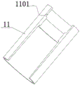
图11为本发明外管上接头四分之一剖视示意图;Fig. 11 is a quarter cross-sectional schematic diagram of the upper joint of the outer pipe of the present invention;
图12为本发明外管下接头四分之一剖视示意图;Fig. 12 is a quarter cross-sectional schematic diagram of the lower joint of the outer pipe of the present invention;
图13为本发明两种锥阀阀瓣三维示意图。Figure 13 is a three-dimensional schematic diagram of two kinds of poppet valve flaps of the present invention.
图中1-内管上接头,101-内螺纹,2-上阀座,201-外螺纹,202-定位轴肩Ⅰ,203-限位轴肩,204-内管壁凸台Ⅰ,3-扶正块Ⅰ,301-过流孔,4-同轴节流滑套,401-内层滑套,402-外层滑套,403-阶梯型锥面密封结构,404-O型密封圈槽Ⅰ,405-O型密封圈槽Ⅱ,406-O型密封圈槽Ⅲ,407-O形密封圈槽Ⅳ,408-分隔板,409-弧形排液孔,5-复位弹簧,6-锥阀安装块,601-销钉孔Ⅰ,602-螺纹孔,7 -销钉,8-凹锥阀阀瓣,801-销钉孔Ⅱ,9-凸锥阀阀瓣,901-销钉孔Ⅲ,10-下阀座,1001-通孔,1002-内管壁凸台Ⅱ,1003-定位轴肩Ⅱ,1004-外螺纹,11-内管下接头,1101-内螺纹,12-扶正块Ⅱ,1201-过流孔,13-外管下接头,1301-定位轴肩Ⅲ,1302-内螺纹,14-外管上接头,1401-定位轴肩Ⅳ,1402-凸台,1403-外螺纹。In the picture 1- upper joint of inner pipe, 101- inner thread, 2- upper valve seat, 201- outer thread, 202- locating shoulder I, 203- limiting shoulder, 204- inner pipe wall boss I, 3- Righting block I, 301-flow hole, 4-coaxial throttle sliding sleeve, 401-inner layer sliding sleeve, 402-outer layer sliding sleeve, 403-stepped cone surface sealing structure, 404-O-type sealing ring groove Ⅰ , 405-O-ring groove Ⅱ, 406-O-ring groove Ⅲ, 407-O-ring groove Ⅳ, 408-dividing plate, 409-arc drain hole, 5-return spring, 6-cone Valve mounting block, 601-pin hole Ⅰ, 602-threaded hole, 7-pin, 8-concave cone valve disc, 801-pin hole Ⅱ, 9-convex cone valve disc, 901-pin hole Ⅲ, 10-down Valve seat, 1001-through hole, 1002-inner pipe wall boss II, 1003-positioning shoulder II, 1004-external thread, 11-inner pipe lower joint, 1101-internal thread, 12-centering block II, 1201-over Orifice, 13-outer pipe lower joint, 1301-positioning shoulder III, 1302-internal thread, 14-outer pipe upper joint, 1401-positioning shoulder IV, 1402- boss, 1403-external thread.
具体实施方式Detailed ways
下面结合附图对本发明做进一步的描述,本发明的保护范围不局限于以下描述:The present invention will be further described below in conjunction with the accompanying drawings, and the protection scope of the present invention is not limited to the following description:
如1所示,一种双层管双梯度控压钻井井下防喷装置,它包括内管上接头1、上阀座2、扶正块Ⅰ3、同轴节流滑套4、复位弹簧5、锥阀安装块6、销钉7、凹锥阀阀瓣8、凸锥阀阀瓣9、下阀座10、内管下接头11、扶正块Ⅱ12、外管下接头13、外管上接头14;内管上接头1与上阀座2通过螺纹连接;其上设置有过流孔的扶正块Ⅰ3通过轴肩定位,安装于上接头与上阀座之间;同轴节流滑套4安装在上阀座与下阀座之间,同轴节流滑套4上的内层滑套401与双层管内管内壁为间隙配合,同轴节流滑套4上的外层套管402与双层管内管外壁为间隙配合;复位弹簧5安装在上阀座2与同轴节流滑套4之间并且设置一定的预紧力;锥阀安装块6与凹锥阀阀瓣8通过销钉7连接;锥阀安装块6与凸锥阀阀瓣9通过销钉7连接;锥阀安装块6与下阀座10通过螺钉连接,下阀座10与内管下接头11通过螺纹连接,其上设置有过流孔的扶正块Ⅱ12通过轴肩定位,安装于下阀座10与内管下接头11之间,最后外管下接头13与外管上接头14通过螺纹连接组成该井下防喷装置的外壳体。As shown in 1, a downhole blowout prevention device for double-layer pipe dual-gradient managed pressure drilling, which includes an inner pipe upper joint 1, an
本发明工作过程如下:The working process of the present invention is as follows:
正常钻进过程中,该井下防喷装置呈开启状态,钻井液从双层管环空泵入,钻井液流入该井下防喷装置上部所连接双层钻杆环空经过外层滑套401与外管上接头14内壁组成的环形通道,流入该井下防喷装置下部所连接的双层钻杆环空直至井底,经过底部钻头后钻井液携带岩屑从内管通道返回,携带岩屑的钻井液通过该井下防喷装置的内层滑套401时,在变径段由于过流通道逐渐变小,变径段处大径端压力大于小径端压力,从而形成压降,在变径段产生向上的推力,由于弹簧预紧力的存在,同轴节流滑套4不会被推动,该井下防喷装置保持开启状态,钻井液携带岩屑从内管通道返回至地面泥浆系统。During the normal drilling process, the downhole blowout preventer is in the open state, the drilling fluid is pumped from the double-layer pipe annulus, and the drilling fluid flows into the double-layer drill pipe annulus connected to the upper part of the downhole blowout preventer through the outer sliding
当钻井过程中遇到井喷等危险工况,井底流体大量快速的通过双层管环空通道,双层管内管通道向上涌出,大量的井底流体从内管上返至该井下防喷装置的内层滑套401时,在内层滑套401变径段大径端压力大于小径端压力,从而形成压降,在变径段产生向上的推力,产生的推力克服复位弹簧5的预紧力,推动同轴节流滑套4沿其轴线向上运动,直至内层滑套401移动至限位轴肩203,此时同轴节流滑套上的阶梯型端面密封结构403与外管上接头14上的凸台1402相配合形成两处锥面密封,井底流体不能再通过双层管内外管环空通道向上涌出。同时覆盖于凹锥阀阀瓣8以及凸锥阀阀瓣9上的内层滑套401下部小径端同时向上运动,安装于锥阀安装块6上的凸锥阀阀瓣9在井底流体作用下开始闭合,凹锥阀阀瓣8在井底流体的作用与凸锥阀阀瓣9的同时作用下开始闭合,四个锥阀阀瓣完全闭合时,双层管内管通道被封堵,井底流体不能再通过双层管内管通道向上涌出,至此双层管井下防喷装置从开启状态转为关闭状态。当压井工作完成后井底压力降低,在复位弹簧5作用下,同轴节流滑套顶开凹锥阀阀瓣8以及凸锥阀阀瓣9,双层管井下防喷阀重新自动开启,保证钻井的继续。When encountering dangerous conditions such as blowout during the drilling process, a large amount of bottom-hole fluid quickly passes through the double-layer pipe annulus, and the inner pipe channel of the double-layer pipe flows upward, and a large amount of bottom-hole fluid returns from the inner pipe to the downhole blowout prevention. When the inner sliding
由上所述,本发明一种双层管双梯度控压钻井井下防喷装置,在井底发生井喷时,井底大量上返的流体流经该防喷装置的内层滑套,在节流作用下,产生向上的推力,推力克服复位弹簧的预紧力,推动同轴节流滑套沿轴向运动,直至同外层滑套上的阶梯型锥面密封结构与外管上接头上设置的凸台相配合完成双层管内外管环空通道封堵,同时由于覆盖在锥阀阀瓣上的内层滑套下部小径端沿轴线向上移动,锥阀阀瓣在流体作用下闭合完成双层管内管通道封堵。至此井底流体不能再通过双层管两处通道向上涌出,双层管井下防喷装置由开到闭的状态转换完成,双层管内外管环空,双层管内管通道被完全封堵,当压井完成后在复位弹簧的作用下,双层管井下防喷装置自动开启继续使用。本发明能够在井底发生井喷等危险工况时对双层管内外管环空,双层管内管通道实现同时完全封堵,能够有效防止由于井喷导致的钻井事故的发生。From the above, the present invention is a downhole blowout prevention device for double-layer pipe dual-gradient pressure-controlled drilling. When a blowout occurs at the bottom of the well, a large amount of fluid returning from the bottom of the well flows through the inner sliding sleeve of the blowout prevention device. Under the action of the flow, an upward thrust is generated, and the thrust overcomes the pre-tightening force of the return spring and pushes the coaxial throttling sliding sleeve to move in the axial direction until the stepped cone sealing structure on the same outer sliding sleeve and the joint on the outer pipe The set bosses cooperate to complete the sealing of the annular channel of the inner and outer tubes of the double-layer tube. At the same time, because the lower small diameter end of the inner layer sliding sleeve covering the poppet valve disc moves up along the axis, the poppet valve disc is closed under the action of fluid. The inner tube channel of the double-layer tube is blocked. So far, the bottom hole fluid can no longer flow upward through the two channels of the double-layer pipe. The downhole blowout preventer of the double-layer pipe is switched from the open to the closed state. The inner and outer pipes of the double-layer pipe are annular, and the inner pipe channel of the double-layer pipe is completely blocked. , When the well kill is completed, under the action of the return spring, the double-layer pipe downhole blowout preventer will automatically open and continue to use. The invention can annulate the inner and outer pipes of the double-layer pipe when a dangerous condition such as a blowout occurs at the bottom of the well, and the channels of the inner pipe of the double-layer pipe can be completely blocked at the same time, which can effectively prevent the occurrence of drilling accidents caused by the blowout.
最后所应说明的是:以上实施例仅用以说明而非限制本发明的技术方案,尽管参照上述实施例对本发明进行了详细说明,本领域的普通技术人员应该理解:依然可以对本专利进行修改或者等同替换,而不脱离本发明的精神和范围的任何修改或局部替换,其均应涵盖在本发明的权利要求范围当中。Finally, it should be noted that the above embodiments are only used to illustrate rather than limit the technical solutions of the present invention. Although the present invention has been described in detail with reference to the above embodiments, those of ordinary skill in the art should understand that: this patent can still be modified. Or equivalent replacements, without departing from the spirit and scope of the present invention, any modifications or partial replacements shall be included in the scope of the claims of the present invention.
Claims (9)
Priority Applications (1)
| Application Number | Priority Date | Filing Date | Title |
|---|---|---|---|
| CN202010896553.5A CN111779464B (en) | 2020-08-31 | 2020-08-31 | Double-layer pipe double-gradient pressure control drilling underground blowout preventer |
Applications Claiming Priority (1)
| Application Number | Priority Date | Filing Date | Title |
|---|---|---|---|
| CN202010896553.5A CN111779464B (en) | 2020-08-31 | 2020-08-31 | Double-layer pipe double-gradient pressure control drilling underground blowout preventer |
Publications (2)
| Publication Number | Publication Date |
|---|---|
| CN111779464A true CN111779464A (en) | 2020-10-16 |
| CN111779464B CN111779464B (en) | 2021-01-05 |
Family
ID=72762285
Family Applications (1)
| Application Number | Title | Priority Date | Filing Date |
|---|---|---|---|
| CN202010896553.5A Active CN111779464B (en) | 2020-08-31 | 2020-08-31 | Double-layer pipe double-gradient pressure control drilling underground blowout preventer |
Country Status (1)
| Country | Link |
|---|---|
| CN (1) | CN111779464B (en) |
Cited By (4)
| Publication number | Priority date | Publication date | Assignee | Title |
|---|---|---|---|---|
| CN113090219A (en) * | 2021-06-09 | 2021-07-09 | 西南石油大学 | Downhole blowout preventer |
| CN113445962A (en) * | 2021-06-24 | 2021-09-28 | 西南石油大学 | Hydraulic double-layer pipe double-gradient downhole blowout prevention valve |
| CN113863888A (en) * | 2021-10-18 | 2021-12-31 | 西南石油大学 | Underground three-channel integrated blowout preventer for double-pipe drilling |
| CN113863866A (en) * | 2021-10-21 | 2021-12-31 | 盐城市荣嘉机械制造有限公司 | Blowout prevention and anti-reflux drill bit |
Citations (8)
| Publication number | Priority date | Publication date | Assignee | Title |
|---|---|---|---|---|
| CN201059187Y (en) * | 2006-11-24 | 2008-05-14 | 中国海洋石油总公司 | A Controlled Pressure Drilling Device Based on Dual Gradients |
| US20120103619A1 (en) * | 2010-10-29 | 2012-05-03 | Hydril Usa Manufacturing Llc | Drill String Valve and Method |
| CN205978489U (en) * | 2016-06-29 | 2017-02-22 | 宝鸡石油机械有限责任公司 | Downhole safety is pombe face seal valve plate disk seat for valve |
| CN109763771A (en) * | 2019-01-16 | 2019-05-17 | 西南石油大学 | A dual gradient drilling system and method based on coiled tubing electric drive |
| CN110593777A (en) * | 2019-10-08 | 2019-12-20 | 西南石油大学 | A riser-free dual-gradient drilling drill string release tie-back device |
| US10577878B2 (en) * | 2017-06-12 | 2020-03-03 | Ameriforge Group Inc. | Dual gradient drilling system and method |
| CN210239647U (en) * | 2019-04-03 | 2020-04-03 | 江苏新彩阳机电技术有限公司 | Downhole sliding sleeve type blowout prevention switch valve |
| CN111456681A (en) * | 2020-06-08 | 2020-07-28 | 西南石油大学 | Double-layer in-pipe blowout prevention valve |
-
2020
- 2020-08-31 CN CN202010896553.5A patent/CN111779464B/en active Active
Patent Citations (8)
| Publication number | Priority date | Publication date | Assignee | Title |
|---|---|---|---|---|
| CN201059187Y (en) * | 2006-11-24 | 2008-05-14 | 中国海洋石油总公司 | A Controlled Pressure Drilling Device Based on Dual Gradients |
| US20120103619A1 (en) * | 2010-10-29 | 2012-05-03 | Hydril Usa Manufacturing Llc | Drill String Valve and Method |
| CN205978489U (en) * | 2016-06-29 | 2017-02-22 | 宝鸡石油机械有限责任公司 | Downhole safety is pombe face seal valve plate disk seat for valve |
| US10577878B2 (en) * | 2017-06-12 | 2020-03-03 | Ameriforge Group Inc. | Dual gradient drilling system and method |
| CN109763771A (en) * | 2019-01-16 | 2019-05-17 | 西南石油大学 | A dual gradient drilling system and method based on coiled tubing electric drive |
| CN210239647U (en) * | 2019-04-03 | 2020-04-03 | 江苏新彩阳机电技术有限公司 | Downhole sliding sleeve type blowout prevention switch valve |
| CN110593777A (en) * | 2019-10-08 | 2019-12-20 | 西南石油大学 | A riser-free dual-gradient drilling drill string release tie-back device |
| CN111456681A (en) * | 2020-06-08 | 2020-07-28 | 西南石油大学 | Double-layer in-pipe blowout prevention valve |
Cited By (6)
| Publication number | Priority date | Publication date | Assignee | Title |
|---|---|---|---|---|
| CN113090219A (en) * | 2021-06-09 | 2021-07-09 | 西南石油大学 | Downhole blowout preventer |
| CN113445962A (en) * | 2021-06-24 | 2021-09-28 | 西南石油大学 | Hydraulic double-layer pipe double-gradient downhole blowout prevention valve |
| CN113445962B (en) * | 2021-06-24 | 2022-05-31 | 西南石油大学 | Hydraulic double-layer pipe double-gradient downhole blowout prevention valve |
| CN113863888A (en) * | 2021-10-18 | 2021-12-31 | 西南石油大学 | Underground three-channel integrated blowout preventer for double-pipe drilling |
| CN113863888B (en) * | 2021-10-18 | 2022-06-17 | 西南石油大学 | Underground three-channel integrated blowout preventer for double-tube drilling |
| CN113863866A (en) * | 2021-10-21 | 2021-12-31 | 盐城市荣嘉机械制造有限公司 | Blowout prevention and anti-reflux drill bit |
Also Published As
| Publication number | Publication date |
|---|---|
| CN111779464B (en) | 2021-01-05 |
Similar Documents
| Publication | Publication Date | Title |
|---|---|---|
| CN111779464A (en) | Downhole blowout preventer for double-layer tubular dual-gradient managed pressure drilling | |
| CN113107436B (en) | Self-locking safety valve for deep sea gas hydrate double-pipe mining | |
| US2798561A (en) | Blowout preventer for wells | |
| CN110700801B (en) | Automatic jet flow crushing tool for solid fluidization exploitation of natural gas hydrate | |
| US6779543B2 (en) | BOP operating system with quick dump valve | |
| US6712145B2 (en) | Float collar | |
| US4254836A (en) | Methods and apparatus for controlling fluid flow | |
| US3698426A (en) | Mud saver valve and method | |
| US4220176A (en) | Methods and apparatus for controlling fluid flow | |
| CA2387195A1 (en) | Fill up tool and mud saver for top drives | |
| US3886967A (en) | Downhole safety ball valve | |
| CN109736737A (en) | Method for snubbing tripping of reservoir gas drilling well | |
| CN108915660A (en) | Fracturing method of coiled tubing with internal blowout prevention function | |
| WO2020036920A1 (en) | Deep set production tubing pressure insensitive wireline retrievable safety valve | |
| US3025919A (en) | Reverse opening circulating sub | |
| CN111456681A (en) | Double-layer in-pipe blowout prevention valve | |
| CN113863888B (en) | Underground three-channel integrated blowout preventer for double-tube drilling | |
| CN113445962B (en) | Hydraulic double-layer pipe double-gradient downhole blowout prevention valve | |
| US9347286B2 (en) | Flow stop valve | |
| CN107387002B (en) | Double-channel plug valve | |
| US3382921A (en) | Method and apparatus for installing an underwater well | |
| US2962099A (en) | Blowout control valve | |
| CN116265692A (en) | Half-way well cementation floating shoe device, tubular column and half-way well cementation operation method | |
| US3130789A (en) | Automatic fill-up and cementing devices for well pipes | |
| US2354310A (en) | Back-pressure valve |
Legal Events
| Date | Code | Title | Description |
|---|---|---|---|
| PB01 | Publication | ||
| PB01 | Publication | ||
| SE01 | Entry into force of request for substantive examination | ||
| SE01 | Entry into force of request for substantive examination | ||
| GR01 | Patent grant | ||
| GR01 | Patent grant |