CN111683751A - sample holder - Google Patents
sample holder Download PDFInfo
- Publication number
- CN111683751A CN111683751A CN201980009744.0A CN201980009744A CN111683751A CN 111683751 A CN111683751 A CN 111683751A CN 201980009744 A CN201980009744 A CN 201980009744A CN 111683751 A CN111683751 A CN 111683751A
- Authority
- CN
- China
- Prior art keywords
- sample
- sample holder
- fluid
- gas
- microstructures
- Prior art date
- Legal status (The legal status is an assumption and is not a legal conclusion. Google has not performed a legal analysis and makes no representation as to the accuracy of the status listed.)
- Granted
Links
Images


Classifications
-
- B—PERFORMING OPERATIONS; TRANSPORTING
- B01—PHYSICAL OR CHEMICAL PROCESSES OR APPARATUS IN GENERAL
- B01L—CHEMICAL OR PHYSICAL LABORATORY APPARATUS FOR GENERAL USE
- B01L3/00—Containers or dishes for laboratory use, e.g. laboratory glassware; Droppers
- B01L3/50—Containers for the purpose of retaining a material to be analysed, e.g. test tubes
- B01L3/502—Containers for the purpose of retaining a material to be analysed, e.g. test tubes with fluid transport, e.g. in multi-compartment structures
- B01L3/5027—Containers for the purpose of retaining a material to be analysed, e.g. test tubes with fluid transport, e.g. in multi-compartment structures by integrated microfluidic structures, i.e. dimensions of channels and chambers are such that surface tension forces are important, e.g. lab-on-a-chip
- B01L3/502715—Containers for the purpose of retaining a material to be analysed, e.g. test tubes with fluid transport, e.g. in multi-compartment structures by integrated microfluidic structures, i.e. dimensions of channels and chambers are such that surface tension forces are important, e.g. lab-on-a-chip characterised by interfacing components, e.g. fluidic, electrical, optical or mechanical interfaces
-
- B—PERFORMING OPERATIONS; TRANSPORTING
- B01—PHYSICAL OR CHEMICAL PROCESSES OR APPARATUS IN GENERAL
- B01L—CHEMICAL OR PHYSICAL LABORATORY APPARATUS FOR GENERAL USE
- B01L3/00—Containers or dishes for laboratory use, e.g. laboratory glassware; Droppers
- B01L3/50—Containers for the purpose of retaining a material to be analysed, e.g. test tubes
- B01L3/502—Containers for the purpose of retaining a material to be analysed, e.g. test tubes with fluid transport, e.g. in multi-compartment structures
- B01L3/5027—Containers for the purpose of retaining a material to be analysed, e.g. test tubes with fluid transport, e.g. in multi-compartment structures by integrated microfluidic structures, i.e. dimensions of channels and chambers are such that surface tension forces are important, e.g. lab-on-a-chip
- B01L3/502707—Containers for the purpose of retaining a material to be analysed, e.g. test tubes with fluid transport, e.g. in multi-compartment structures by integrated microfluidic structures, i.e. dimensions of channels and chambers are such that surface tension forces are important, e.g. lab-on-a-chip characterised by the manufacture of the container or its components
-
- B—PERFORMING OPERATIONS; TRANSPORTING
- B01—PHYSICAL OR CHEMICAL PROCESSES OR APPARATUS IN GENERAL
- B01L—CHEMICAL OR PHYSICAL LABORATORY APPARATUS FOR GENERAL USE
- B01L3/00—Containers or dishes for laboratory use, e.g. laboratory glassware; Droppers
- B01L3/50—Containers for the purpose of retaining a material to be analysed, e.g. test tubes
- B01L3/502—Containers for the purpose of retaining a material to be analysed, e.g. test tubes with fluid transport, e.g. in multi-compartment structures
- B01L3/5027—Containers for the purpose of retaining a material to be analysed, e.g. test tubes with fluid transport, e.g. in multi-compartment structures by integrated microfluidic structures, i.e. dimensions of channels and chambers are such that surface tension forces are important, e.g. lab-on-a-chip
- B01L3/502723—Containers for the purpose of retaining a material to be analysed, e.g. test tubes with fluid transport, e.g. in multi-compartment structures by integrated microfluidic structures, i.e. dimensions of channels and chambers are such that surface tension forces are important, e.g. lab-on-a-chip characterised by venting arrangements
-
- B—PERFORMING OPERATIONS; TRANSPORTING
- B01—PHYSICAL OR CHEMICAL PROCESSES OR APPARATUS IN GENERAL
- B01L—CHEMICAL OR PHYSICAL LABORATORY APPARATUS FOR GENERAL USE
- B01L9/00—Supporting devices; Holding devices
-
- C—CHEMISTRY; METALLURGY
- C12—BIOCHEMISTRY; BEER; SPIRITS; WINE; VINEGAR; MICROBIOLOGY; ENZYMOLOGY; MUTATION OR GENETIC ENGINEERING
- C12M—APPARATUS FOR ENZYMOLOGY OR MICROBIOLOGY; APPARATUS FOR CULTURING MICROORGANISMS FOR PRODUCING BIOMASS, FOR GROWING CELLS OR FOR OBTAINING FERMENTATION OR METABOLIC PRODUCTS, i.e. BIOREACTORS OR FERMENTERS
- C12M23/00—Constructional details, e.g. recesses, hinges
- C12M23/02—Form or structure of the vessel
- C12M23/16—Microfluidic devices; Capillary tubes
-
- C—CHEMISTRY; METALLURGY
- C12—BIOCHEMISTRY; BEER; SPIRITS; WINE; VINEGAR; MICROBIOLOGY; ENZYMOLOGY; MUTATION OR GENETIC ENGINEERING
- C12M—APPARATUS FOR ENZYMOLOGY OR MICROBIOLOGY; APPARATUS FOR CULTURING MICROORGANISMS FOR PRODUCING BIOMASS, FOR GROWING CELLS OR FOR OBTAINING FERMENTATION OR METABOLIC PRODUCTS, i.e. BIOREACTORS OR FERMENTERS
- C12M23/00—Constructional details, e.g. recesses, hinges
- C12M23/26—Constructional details, e.g. recesses, hinges flexible
-
- C—CHEMISTRY; METALLURGY
- C12—BIOCHEMISTRY; BEER; SPIRITS; WINE; VINEGAR; MICROBIOLOGY; ENZYMOLOGY; MUTATION OR GENETIC ENGINEERING
- C12M—APPARATUS FOR ENZYMOLOGY OR MICROBIOLOGY; APPARATUS FOR CULTURING MICROORGANISMS FOR PRODUCING BIOMASS, FOR GROWING CELLS OR FOR OBTAINING FERMENTATION OR METABOLIC PRODUCTS, i.e. BIOREACTORS OR FERMENTERS
- C12M41/00—Means for regulation, monitoring, measurement or control, e.g. flow regulation
-
- C—CHEMISTRY; METALLURGY
- C12—BIOCHEMISTRY; BEER; SPIRITS; WINE; VINEGAR; MICROBIOLOGY; ENZYMOLOGY; MUTATION OR GENETIC ENGINEERING
- C12Q—MEASURING OR TESTING PROCESSES INVOLVING ENZYMES, NUCLEIC ACIDS OR MICROORGANISMS; COMPOSITIONS OR TEST PAPERS THEREFOR; PROCESSES OF PREPARING SUCH COMPOSITIONS; CONDITION-RESPONSIVE CONTROL IN MICROBIOLOGICAL OR ENZYMOLOGICAL PROCESSES
- C12Q1/00—Measuring or testing processes involving enzymes, nucleic acids or microorganisms; Compositions therefor; Processes of preparing such compositions
- C12Q1/02—Measuring or testing processes involving enzymes, nucleic acids or microorganisms; Compositions therefor; Processes of preparing such compositions involving viable microorganisms
- C12Q1/18—Testing for antimicrobial activity of a material
-
- G—PHYSICS
- G01—MEASURING; TESTING
- G01N—INVESTIGATING OR ANALYSING MATERIALS BY DETERMINING THEIR CHEMICAL OR PHYSICAL PROPERTIES
- G01N21/00—Investigating or analysing materials by the use of optical means, i.e. using sub-millimetre waves, infrared, visible or ultraviolet light
- G01N21/01—Arrangements or apparatus for facilitating the optical investigation
- G01N21/03—Cuvette constructions
-
- B—PERFORMING OPERATIONS; TRANSPORTING
- B01—PHYSICAL OR CHEMICAL PROCESSES OR APPARATUS IN GENERAL
- B01L—CHEMICAL OR PHYSICAL LABORATORY APPARATUS FOR GENERAL USE
- B01L2200/00—Solutions for specific problems relating to chemical or physical laboratory apparatus
- B01L2200/02—Adapting objects or devices to another
- B01L2200/026—Fluid interfacing between devices or objects, e.g. connectors, inlet details
- B01L2200/027—Fluid interfacing between devices or objects, e.g. connectors, inlet details for microfluidic devices
-
- B—PERFORMING OPERATIONS; TRANSPORTING
- B01—PHYSICAL OR CHEMICAL PROCESSES OR APPARATUS IN GENERAL
- B01L—CHEMICAL OR PHYSICAL LABORATORY APPARATUS FOR GENERAL USE
- B01L2200/00—Solutions for specific problems relating to chemical or physical laboratory apparatus
- B01L2200/06—Fluid handling related problems
- B01L2200/0642—Filling fluids into wells by specific techniques
-
- B—PERFORMING OPERATIONS; TRANSPORTING
- B01—PHYSICAL OR CHEMICAL PROCESSES OR APPARATUS IN GENERAL
- B01L—CHEMICAL OR PHYSICAL LABORATORY APPARATUS FOR GENERAL USE
- B01L2200/00—Solutions for specific problems relating to chemical or physical laboratory apparatus
- B01L2200/06—Fluid handling related problems
- B01L2200/0684—Venting, avoiding backpressure, avoid gas bubbles
-
- B—PERFORMING OPERATIONS; TRANSPORTING
- B01—PHYSICAL OR CHEMICAL PROCESSES OR APPARATUS IN GENERAL
- B01L—CHEMICAL OR PHYSICAL LABORATORY APPARATUS FOR GENERAL USE
- B01L2300/00—Additional constructional details
- B01L2300/04—Closures and closing means
- B01L2300/041—Connecting closures to device or container
-
- B—PERFORMING OPERATIONS; TRANSPORTING
- B01—PHYSICAL OR CHEMICAL PROCESSES OR APPARATUS IN GENERAL
- B01L—CHEMICAL OR PHYSICAL LABORATORY APPARATUS FOR GENERAL USE
- B01L2300/00—Additional constructional details
- B01L2300/04—Closures and closing means
- B01L2300/046—Function or devices integrated in the closure
- B01L2300/047—Additional chamber, reservoir
-
- B—PERFORMING OPERATIONS; TRANSPORTING
- B01—PHYSICAL OR CHEMICAL PROCESSES OR APPARATUS IN GENERAL
- B01L—CHEMICAL OR PHYSICAL LABORATORY APPARATUS FOR GENERAL USE
- B01L2300/00—Additional constructional details
- B01L2300/04—Closures and closing means
- B01L2300/046—Function or devices integrated in the closure
- B01L2300/048—Function or devices integrated in the closure enabling gas exchange, e.g. vents
-
- B—PERFORMING OPERATIONS; TRANSPORTING
- B01—PHYSICAL OR CHEMICAL PROCESSES OR APPARATUS IN GENERAL
- B01L—CHEMICAL OR PHYSICAL LABORATORY APPARATUS FOR GENERAL USE
- B01L2300/00—Additional constructional details
- B01L2300/06—Auxiliary integrated devices, integrated components
-
- B—PERFORMING OPERATIONS; TRANSPORTING
- B01—PHYSICAL OR CHEMICAL PROCESSES OR APPARATUS IN GENERAL
- B01L—CHEMICAL OR PHYSICAL LABORATORY APPARATUS FOR GENERAL USE
- B01L2300/00—Additional constructional details
- B01L2300/06—Auxiliary integrated devices, integrated components
- B01L2300/0609—Holders integrated in container to position an object
-
- B—PERFORMING OPERATIONS; TRANSPORTING
- B01—PHYSICAL OR CHEMICAL PROCESSES OR APPARATUS IN GENERAL
- B01L—CHEMICAL OR PHYSICAL LABORATORY APPARATUS FOR GENERAL USE
- B01L2300/00—Additional constructional details
- B01L2300/08—Geometry, shape and general structure
- B01L2300/0803—Disc shape
- B01L2300/0806—Standardised forms, e.g. compact disc [CD] format
-
- B—PERFORMING OPERATIONS; TRANSPORTING
- B01—PHYSICAL OR CHEMICAL PROCESSES OR APPARATUS IN GENERAL
- B01L—CHEMICAL OR PHYSICAL LABORATORY APPARATUS FOR GENERAL USE
- B01L2300/00—Additional constructional details
- B01L2300/08—Geometry, shape and general structure
- B01L2300/0809—Geometry, shape and general structure rectangular shaped
- B01L2300/0819—Microarrays; Biochips
-
- B—PERFORMING OPERATIONS; TRANSPORTING
- B01—PHYSICAL OR CHEMICAL PROCESSES OR APPARATUS IN GENERAL
- B01L—CHEMICAL OR PHYSICAL LABORATORY APPARATUS FOR GENERAL USE
- B01L2300/00—Additional constructional details
- B01L2300/08—Geometry, shape and general structure
- B01L2300/0861—Configuration of multiple channels and/or chambers in a single devices
- B01L2300/0864—Configuration of multiple channels and/or chambers in a single devices comprising only one inlet and multiple receiving wells, e.g. for separation, splitting
-
- B—PERFORMING OPERATIONS; TRANSPORTING
- B01—PHYSICAL OR CHEMICAL PROCESSES OR APPARATUS IN GENERAL
- B01L—CHEMICAL OR PHYSICAL LABORATORY APPARATUS FOR GENERAL USE
- B01L2300/00—Additional constructional details
- B01L2300/12—Specific details about materials
- B01L2300/123—Flexible; Elastomeric
-
- B—PERFORMING OPERATIONS; TRANSPORTING
- B01—PHYSICAL OR CHEMICAL PROCESSES OR APPARATUS IN GENERAL
- B01L—CHEMICAL OR PHYSICAL LABORATORY APPARATUS FOR GENERAL USE
- B01L2300/00—Additional constructional details
- B01L2300/16—Surface properties and coatings
- B01L2300/161—Control and use of surface tension forces, e.g. hydrophobic, hydrophilic
- B01L2300/165—Specific details about hydrophobic, oleophobic surfaces
-
- B—PERFORMING OPERATIONS; TRANSPORTING
- B01—PHYSICAL OR CHEMICAL PROCESSES OR APPARATUS IN GENERAL
- B01L—CHEMICAL OR PHYSICAL LABORATORY APPARATUS FOR GENERAL USE
- B01L2300/00—Additional constructional details
- B01L2300/16—Surface properties and coatings
- B01L2300/168—Specific optical properties, e.g. reflective coatings
-
- B—PERFORMING OPERATIONS; TRANSPORTING
- B01—PHYSICAL OR CHEMICAL PROCESSES OR APPARATUS IN GENERAL
- B01L—CHEMICAL OR PHYSICAL LABORATORY APPARATUS FOR GENERAL USE
- B01L2400/00—Moving or stopping fluids
- B01L2400/08—Regulating or influencing the flow resistance
- B01L2400/084—Passive control of flow resistance
- B01L2400/088—Passive control of flow resistance by specific surface properties
-
- G—PHYSICS
- G01—MEASURING; TESTING
- G01N—INVESTIGATING OR ANALYSING MATERIALS BY DETERMINING THEIR CHEMICAL OR PHYSICAL PROPERTIES
- G01N21/00—Investigating or analysing materials by the use of optical means, i.e. using sub-millimetre waves, infrared, visible or ultraviolet light
- G01N21/01—Arrangements or apparatus for facilitating the optical investigation
- G01N21/03—Cuvette constructions
- G01N2021/0346—Capillary cells; Microcells
- G01N2021/035—Supports for sample drops
Landscapes
- Chemical & Material Sciences (AREA)
- Health & Medical Sciences (AREA)
- General Health & Medical Sciences (AREA)
- Life Sciences & Earth Sciences (AREA)
- Organic Chemistry (AREA)
- Analytical Chemistry (AREA)
- Clinical Laboratory Science (AREA)
- Zoology (AREA)
- Wood Science & Technology (AREA)
- Engineering & Computer Science (AREA)
- Bioinformatics & Cheminformatics (AREA)
- Chemical Kinetics & Catalysis (AREA)
- Dispersion Chemistry (AREA)
- Hematology (AREA)
- Biochemistry (AREA)
- Biotechnology (AREA)
- Microbiology (AREA)
- General Engineering & Computer Science (AREA)
- Genetics & Genomics (AREA)
- Biomedical Technology (AREA)
- Sustainable Development (AREA)
- Physics & Mathematics (AREA)
- Immunology (AREA)
- Proteomics, Peptides & Aminoacids (AREA)
- General Physics & Mathematics (AREA)
- Pathology (AREA)
- Toxicology (AREA)
- Biophysics (AREA)
- Molecular Biology (AREA)
- Automatic Analysis And Handling Materials Therefor (AREA)
Abstract
Description
技术领域technical field
本发明涉及在样品分析中使用的样品架。在一些实例中,样品分析涉及检测样品中的微观物体(如微观生物物体)的存在、量和/或不存在。The present invention relates to sample holders for use in sample analysis. In some instances, sample analysis involves detecting the presence, amount, and/or absence of microscopic objects (eg, microscopic biological objects) in the sample.
背景技术Background technique
在各个领域中,重要的是能够快速有效地分析样品,尤其是能够检测和/或计数小物体,如生物粒子、分子、细胞等。然而,仍然需要进一步改善在该领域中使用的样品架的能力。In various fields, it is important to be able to analyze samples quickly and efficiently, especially to be able to detect and/or count small objects such as biological particles, molecules, cells, etc. However, there is still a need to further improve the capabilities of sample holders used in this field.
发明内容SUMMARY OF THE INVENTION
根据第一方面,本发明提供一种样品架,其包括:According to a first aspect, the present invention provides a sample holder comprising:
上层;upper layer;
下层;lower layer;
在上层与下层之间的中间层;和an intermediate layer between the upper layer and the lower layer; and
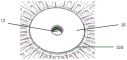
由所述中间层中的通孔形成的样品室,在其上部被所述上层的底面的一部分遮盖,且在其下部被所述下层的顶面的一部分遮盖,a sample chamber formed by a through hole in the intermediate layer, covered at its upper portion by a portion of the bottom surface of the upper layer, and covered at its lower portion by a portion of the top surface of the lower layer,
其中与所述样品室的顶部周缘的一部分重叠的所述上层的底面的至少一部分包括疏水表面,wherein at least a portion of the bottom surface of the upper layer that overlaps a portion of the top perimeter of the sample chamber includes a hydrophobic surface,
并且其中在所述疏水表面上水滴的接触角超过110°。And where the contact angle of water droplets on said hydrophobic surface exceeds 110°.
因此,本文中提到“疏水表面”是指水滴在所述表面上的接触角超过110°的疏水表面。任选地,接触角超过120°。接触角可以在120°至140°之间,或者可以超过140°,或者可以超过150°(在这种情况下,表面是超疏水性的)。Thus, reference herein to a "hydrophobic surface" refers to a hydrophobic surface having a contact angle of water droplets on said surface in excess of 110°. Optionally, the contact angle exceeds 120°. The contact angle may be between 120° and 140°, or may exceed 140°, or may exceed 150° (in which case the surface is superhydrophobic).
疏水表面可以是双疏性的,这意味着除了疏水之外,该表面也是疏油的。在此类情况下,油滴在双疏性表面上的接触角可以超过110°。任选地,接触角超过120°。接触角可以在120°至140°之间,或者可以超过140°,或者可以超过150°。A hydrophobic surface can be amphiphobic, which means that in addition to being hydrophobic, the surface is also oleophobic. In such cases, the contact angle of the oil droplet on the amphiphobic surface can exceed 110°. Optionally, the contact angle exceeds 120°. The contact angle may be between 120° and 140°, or may exceed 140°, or may exceed 150°.
在水滴在表面上的接触角超过150°并且油滴在表面上的接触角超过150°的情况下,将该表面认为是超双疏性的。Where the contact angle of water droplets on the surface exceeds 150° and the contact angle of oil droplets on the surface exceeds 150°, the surface is considered superamphiphobic.
在下面的讨论中,对“疏水表面”的提及应理解为覆盖“双疏性表面”(除了在明确讨论为疏水性而不是双疏性表面的情况下),因为双疏性表面是疏水表面的特殊情况。根据定义,双疏性表面也是疏水性的,但是疏水表面不一定是双疏性的。In the discussion below, references to "hydrophobic surfaces" should be understood to cover "amphiphobic surfaces" (except where explicitly discussed as hydrophobic rather than amphiphobic surfaces), since amphiphobic surfaces are hydrophobic special case of the surface. An amphiphobic surface is also hydrophobic by definition, but a hydrophobic surface is not necessarily amphiphobic.
因此,样品室在其上周缘至少部分地以疏水表面为边界。术语“顶部周缘”在本文中是指界定样品室顶面的边缘。疏水表面可以绕所述样品室的整个顶部周缘延伸,或仅仅绕该周缘的一部分延伸。就其在样品室周缘内的范围而言(并且不限制在样品室周缘之外的疏水表面的范围),疏水表面可以仅绕周缘(或其一部分)延伸,或者也可以在样品室的整个上表面的一部分或全部上延伸。疏水表面可以从样品室的周缘向外延伸。Thus, the sample chamber is at least partially bounded by a hydrophobic surface at its upper periphery. The term "top perimeter" refers herein to the edge that defines the top surface of the sample chamber. The hydrophobic surface may extend around the entire top perimeter of the sample chamber, or only around a portion of the perimeter. In terms of its extent within the perimeter of the sample chamber (and not limited to the extent of the hydrophobic surface outside the perimeter of the sample chamber), the hydrophobic surface may extend only around the perimeter (or a portion thereof), or it may extend over the entirety of the sample chamber. extend over part or all of the surface. The hydrophobic surface may extend outward from the periphery of the sample chamber.
由于覆盖样品室的顶部周缘的至少一部分的表面的疏水性质,当将样品液引入样品室中时,该表面无法被润湿。因此,疏水表面起到将样品密封在样品室中的作用。Due to the hydrophobic nature of the surface covering at least a portion of the top perimeter of the sample chamber, the surface cannot be wetted when the sample liquid is introduced into the sample chamber. Thus, the hydrophobic surface acts to seal the sample in the sample chamber.
样品室可以包括开口,该开口任选地在其底部周缘,以允许将液体样品供应到样品室中。The sample chamber may include an opening, optionally at its bottom perimeter, to allow a liquid sample to be supplied into the sample chamber.
样品室可以在其顶部和底部周缘相对于向外的液体流被密封,其中中间层分别与上层和下层相遇。The sample chamber may be sealed against the outward flow of liquid at its top and bottom peripheries, where the middle layer meets the upper and lower layers, respectively.
在底部周缘处,可以通过将中间层接合至下层的粘合图案,任选地将样品室密封以防液体流出。At the bottom perimeter, the sample chamber can optionally be sealed from liquid escape by an adhesive pattern that joins the middle layer to the lower layer.
在顶部周缘处,样品室任选地通过疏水表面,或部分地通过疏水表面及部分地通过将中间层接合至上层的粘合图案密封以防液体流出。在提到“将中间层接合至上层的粘合图案”的情况下,将理解的是,粘合剂可以仅存在于形成在中间层的顶面开口的孔的任何结构的外部。At the top perimeter, the sample chamber is optionally sealed against liquid runoff by the hydrophobic surface, or partly by the hydrophobic surface and partly by the adhesive pattern joining the middle layer to the upper layer. Where reference is made to "an adhesive pattern joining the intermediate layer to the upper layer", it will be understood that the adhesive may only be present on the outside of any structure formed with apertures open in the top surface of the intermediate layer.
在一些实施方案中,疏水表面仅与样品室的一条顶部边缘(或其一部分)重叠。在那种情况下,可以使用粘合图案在其余的顶部边缘处密封样品室,以避免液体沿着那些边缘渗漏。在上层包括疏水表面的区域中,样品室周围在上层和中间层之间的连续粘合剂可能不是必需的。In some embodiments, the hydrophobic surface overlaps only one top edge (or a portion thereof) of the sample chamber. In that case, an adhesive pattern can be used to seal the sample chamber at the remaining top edges to avoid leakage of liquid along those edges. In areas where the upper layer includes a hydrophobic surface, a continuous adhesive between the upper and middle layers around the sample chamber may not be necessary.
样品室可以是样品液的盲孔,也就是说,尽管可能存在供样品液进入样品室的开口,但是可能不存在样品液的出口。The sample chamber may be a blind hole for the sample liquid, that is, although there may be an opening for the sample liquid to enter the sample chamber, there may be no outlet for the sample liquid.
任选地,如上所述,样品架包括多个样品室。Optionally, as described above, the sample holder includes a plurality of sample compartments.
任选地,上层的整个底面包括疏水表面。Optionally, the entire bottom surface of the upper layer includes a hydrophobic surface.
任选地,疏水表面由微观结构阵列形成。在本文中,微观结构阵列包括在表面中或表面上形成的多个微观结构。微观结构可以以规则的排列分布,例如在相邻微观结构之间具有均匀的间隔。Optionally, the hydrophobic surface is formed from an array of microstructures. As used herein, an array of microstructures includes a plurality of microstructures formed in or on a surface. The microstructures may be distributed in a regular arrangement, eg, with uniform spacing between adjacent microstructures.
任选地,可以设置多个离散的(即至少部分在空间上隔开的)微观结构阵列。每个微观结构阵列可以在多个样品室上延伸。每个微观结构阵列的宽度可以稍大于样品室的宽度。Optionally, a plurality of discrete (ie, at least partially spatially spaced) arrays of microstructures may be provided. Each microstructure array can extend over multiple sample chambers. The width of each microstructure array can be slightly larger than the width of the sample chamber.
例如,在样品架包括沿着样品架的径向线定位的多个样品室的实施方案中,可以设置多个径向延伸的微观结构阵列,每个阵列与样品室(例如,一个流体网络内的样品室,如以下所讨论的)的径向线大致对准。在另一替代方案中,可以提供多个微观结构阵列,每个阵列形成为同心圆,该同心圆覆盖排列在同心圆中的多个样品室(例如,其中样品室可以属于不同的流体网络)。For example, in embodiments where the sample holder includes a plurality of sample chambers positioned along radial lines of the sample holder, a plurality of radially extending arrays of microstructures may be provided, each array being associated with the sample chamber (eg, within a fluid network) of the sample chamber, as discussed below) are approximately aligned with the radial lines. In another alternative, multiple arrays of microstructures may be provided, each array formed as concentric circles covering multiple sample chambers arranged in concentric circles (eg, where the sample chambers may belong to different fluidic networks) .
代替多个离散的微观结构阵列,可以提供单个连续的微观结构阵列。例如,单个连续的微观结构阵列可以基本上遮盖上层的整个底面。可替代地,在样品架包括沿着样品架的径向线定位的多个样品室的实施方案中,可以提供包括多个径向延伸的微观结构“叶片”的微观结构阵列,每个叶片与样品室的径向线大致对准。Instead of multiple discrete arrays of microstructures, a single continuous array of microstructures can be provided. For example, a single continuous array of microstructures may cover substantially the entire bottom surface of the upper layer. Alternatively, in embodiments where the sample holder includes a plurality of sample chambers positioned along a radial line of the sample holder, a microstructure array comprising a plurality of radially extending microstructure "vanes" may be provided, each vane being associated with The radial lines of the sample chamber are roughly aligned.
微观结构阵列的其他配置当然也是可能的。Other configurations of microstructure arrays are of course possible.
在样品架的制造过程中,微观结构阵列可以具有便于与下面的样品室对准的形状。例如,一个或多个微观结构阵列可包括狭窄部分(任选地,多个狭窄部分),此处微观结构阵列的宽度变窄仅比样品室的宽度稍宽。例如,狭窄部分可以设置在径向沿着微观结构阵列的位置以与最外侧的样品室对准。所有的微观结构阵列,或者它们之间仅一个或一些(例如,一半的微观结构阵列,在替代微观结构阵列上设有狭窄部分)可以具有狭窄部分。然后,例如在粘合之前,狭窄部分可以在视觉上与最外侧的样品室旋转对准。During fabrication of the sample holder, the microstructure array may have a shape that facilitates alignment with the underlying sample chamber. For example, one or more of the microstructure arrays may include a narrow section (optionally, a plurality of narrow sections), where the width of the microstructure array narrows only slightly wider than the width of the sample chamber. For example, narrowed sections may be positioned radially along the microstructure array to align with the outermost sample chambers. All of the microstructure arrays, or only one or some of them (eg, half of the microstructure arrays, with a narrowed portion on an alternate microstructure array) may have narrowed sections. The narrow portion can then be visually rotationally aligned with the outermost sample chamber, eg, prior to gluing.
在微观结构阵列的区域(在上层上)和中间层之间存在粘合剂的情况下,任选地,仅形成微观结构阵列的微观结构的尖端粘合至中间层,以维持微观结构之间的间隔。Optionally, only the tips of the microstructures forming the microstructure array are bonded to the intermediate layer in the presence of an adhesive between the regions of the microstructure array (on the upper layer) and the intermediate layer to maintain the interlayer between the microstructures interval.
微观结构的高度可以为25至150μm(例如,大约50μm或100μm)。The height of the microstructures may be 25 to 150 μm (eg, about 50 μm or 100 μm).
微观结构的宽度可以为50至150μm。The width of the microstructures may be 50 to 150 μm.
在一些实施方案中,微观结构可以是长度大于其宽度的延伸结构。在此类实施方案中,微观结构具有肋状结构(微型肋)。可替代地将微观结构描述为脊状(微型脊)。例如,微观结构阵列可以包括高度为25至150μm,宽度为50至150μm及长度为50至20000μm的矩形微观结构。In some embodiments, the microstructures may be elongated structures with a length greater than their width. In such embodiments, the microstructure has a rib-like structure (micro-rib). Alternatively, the microstructures are described as ridges (micro-ridges). For example, an array of microstructures may include rectangular microstructures having a height of 25 to 150 μm, a width of 50 to 150 μm and a length of 50 to 20000 μm.
在设有此类微型肋/微型脊的实施方案中,微型肋/微型脊的长度任选地与它们所覆盖的样品室的顶部边缘成一定角度(例如,大体垂直,而不是平行)取向,使得相邻微型肋/微型脊之间的空间通向样品室。In embodiments provided with such micro-ribs/micro-ridges, the lengths of the micro-ribs/micro-ridges are optionally oriented at an angle (eg, generally perpendicular rather than parallel) to the top edge of the sample chamber they cover, Allow the space between adjacent microribs/ridges to open to the sample chamber.
在其他实施方案中,微观结构可以包括柱状结构,例如,其长度与其宽度相当。因此,微观结构阵列可以包括微型柱,从而形成微型柱阵列。In other embodiments, the microstructures may comprise columnar structures, eg, the length of which is comparable to its width. Thus, the array of microstructures may include micropillars, thereby forming an array of micropillars.
微型柱的高度可以为25至150μm,宽度可以为50至150μm,且长度可以为50至150μm。The micropillars can be 25 to 150 μm in height, 50 to 150 μm in width, and 50 to 150 μm in length.
微型柱在两个相邻的微型柱之间的中心到中心的距离可以为50至150μm(例如,大约100μm)。The center-to-center distance of the micropillars between two adjacent micropillars may be 50 to 150 μm (eg, about 100 μm).
任选地,微型柱的高度与中心到中心的距离的比率为大约1:1。Optionally, the ratio of the height of the micropillars to the center-to-center distance is about 1:1.
微型柱可以具有大致为截头圆锥形的形状(即,具有圆形横截面,并且沿着微型柱的轴具有逐渐减小的直径,直径在上端(即,在距样品室最远的基部)最大,而在下端(即,在最靠近样品室的尖端,在上层和中层之间的边界处)最小)。微型柱尖端的直径任选地为大约50μm,而微型柱基部的直径任选地为大约75μm。微型柱的高度为大约50μm。中心到中心的距离任选地为大约100μm,因此在基部,微型柱之间有25μm的间隙。The microcolumns may have a generally frustoconical shape (ie, with a circular cross-section and a decreasing diameter along the axis of the microcolumn, with the diameter at the upper end (ie, at the base furthest from the sample chamber) largest and smallest at the lower end (ie, at the tip closest to the sample chamber, at the boundary between the upper and middle layers). The diameter of the micro-column tip is optionally about 50 [mu]m, and the diameter of the micro-column base is optionally about 75 [mu]m. The height of the micropillars is approximately 50 μm. The center-to-center distance is optionally about 100 μm, so there is a 25 μm gap between the micropillars at the base.
任选地,微观结构是锥形的。也就是说,微观结构的横截面面积可以在上端(即,在距样品室最远的基部)最大,而在下端(即,在最靠近样品室的尖端,在上层和中层之间的边界处)最小。与非锥形的微观结构(即具有不变横截面的微观结构)相比,此类锥形微观结构更易于通过注塑成型而形成。Optionally, the microstructure is tapered. That is, the cross-sectional area of the microstructure can be largest at the upper end (ie, at the base furthest from the sample chamber) and at the lower end (ie, at the tip closest to the sample chamber, at the boundary between the upper and middle layers) ) minimum. Such tapered microstructures are easier to form by injection molding than non-tapered microstructures (ie, microstructures with a constant cross-section).
微观结构的尖端(即,邻接中间层的末端)可以是平坦的,并且平行于中间层上表面的平面。这有助于微观结构阵列和中间层之间的良好界面。The tips of the microstructures (ie, the ends adjoining the intermediate layer) may be flat and parallel to the plane of the upper surface of the intermediate layer. This contributes to a good interface between the microstructure array and the interlayer.
任选地,微观结构的高度类似于或小于微观结构的最小直径或宽度。Optionally, the height of the microstructures is similar to or less than the smallest diameter or width of the microstructures.
任选地,相邻微观结构之间在其基部的距离为10μm至50μm,例如25μm。Optionally, the distance between adjacent microstructures at their bases is 10 μm to 50 μm, eg 25 μm.
任选地,微观结构阵列中的气体体积为微观结构所遮盖的区域的总体积的20%至60%(任选地为30%至50%)。Optionally, the gas volume in the microstructure array is 20% to 60% (optionally 30% to 50%) of the total volume of the area covered by the microstructures.
微观结构的尺寸和分隔距离的下限可以通过注射成型的限度来设定。微观结构的尺寸和分隔距离的上限可以基于表面具有疏水性的要求来设定。具体而言,微观结构可以具有选择的特征,以防止桥接微观结构尖端的液体接触微观结构的基部。这取决于几个参数,例如微观结构尖端的表面积、微观结构的分隔距离、微观结构的高度以及液体与形成微观结构的材料的接触角等。The lower limit of the size of the microstructure and the separation distance can be set by the limits of injection molding. The upper limit of the size and separation distance of the microstructures can be set based on the requirement that the surface be hydrophobic. Specifically, the microstructures can have features selected to prevent liquid bridging the tips of the microstructures from contacting the base of the microstructures. This depends on several parameters, such as the surface area of the microstructure tips, the separation distance of the microstructures, the height of the microstructures, and the contact angle of the liquid with the material forming the microstructures.
对微观结构的尺寸和分隔距离没有特别限制,只要获得疏水性即可。The size and separation distance of the microstructures are not particularly limited as long as hydrophobicity is obtained.
对微观结构横截面的形状没有特别限制,只要获得疏水性即可。微观结构可以例如具有圆形、卵形、椭圆形、三角形、正方形、矩形、五边形或六边形的横截面,或任何其他规则或不规则的多边形形状。The shape of the cross section of the microstructure is not particularly limited as long as hydrophobicity is obtained. The microstructure may, for example, have a circular, oval, elliptical, triangular, square, rectangular, pentagonal or hexagonal cross-section, or any other regular or irregular polygonal shape.
微观结构可以具有截棱锥的形状,例如具有三角形、正方形、矩形、五边形或六边形的基底面。The microstructures may have the shape of truncated pyramids, eg with triangular, square, rectangular, pentagonal or hexagonal base surfaces.
微观结构阵列可以例如通过注塑成型、蚀刻或冲压形成。The array of microstructures can be formed, for example, by injection molding, etching or stamping.
任选地,微观结构阵列由疏水材料形成。Optionally, the microstructure array is formed from a hydrophobic material.
前述讨论通常适用于形成疏水表面,但是形成的表面也可以不是疏油性的(即,该表面可以不是双疏性的)。The foregoing discussion generally applies to the formation of hydrophobic surfaces, but the surface formed may not be oleophobic (ie, the surface may not be amphiphobic).
在提供双疏性表面的情况下,这可以由与以上讨论的类似微观结构阵列形成,对其进行改良(例如,机械地或化学地)以使该微观结构阵列成为双疏性的。Where an amphiphobic surface is provided, this can be formed from an array of microstructures similar to those discussed above, modified (eg, mechanically or chemically) to make the array of microstructures amphiphobic.
为了制造双疏性表面,在一个实施方案中,对类似于以上阐述的微观结构阵列进行机械改良以提供“悬垂”微观结构。这可以通过如上所述产生微观结构(例如,微型柱),然后压缩微观结构(微型柱)来完成。这可以通过同时加热和压缩微观结构(微型柱)来实现。To create amphiphobic surfaces, in one embodiment, an array of microstructures similar to those set forth above is mechanically modified to provide "overhanging" microstructures. This can be accomplished by creating microstructures (eg, micropillars) as described above, and then compressing the microstructures (micropillars). This can be achieved by simultaneously heating and compressing the microstructures (micropillars).
可以考虑应获得的悬垂物的尺寸来选择未压缩的微观结构(微型柱)之间的距离。The distance between the uncompressed microstructures (micropillars) can be chosen taking into account the size of the overhang that should be obtained.
微观结构具有宽度W,并且悬垂物在该宽度上突出悬垂宽度w。w的值可以是微观结构宽度W的0.25至1.5倍。于是压缩微观结构的总宽度W'(W+2w)可以在1.5W至4W的范围内。The microstructure has a width W, and the overhang protrudes over this width by the overhang width w. The value of w may be 0.25 to 1.5 times the width W of the microstructure. The overall width W'(W+2w) of the compressed microstructures may then be in the range of 1.5W to 4W.
例如,如果W为50μm,则w可以为12.5μm至75μm,使得W'为75μm至200μm。For example, if W is 50 μm, then w may be 12.5 μm to 75 μm, such that W′ is 75 μm to 200 μm.
压缩的悬垂微观结构的尖端任选地不彼此接触。The tips of the compressed overhanging microstructures are optionally not in contact with each other.
作为使用机械手段来改良微观结构阵列的替代方案,可以改良微观结构阵列的表面化学以提供双疏性表面。此类化学改良方法在本领域中是已知的,在此不进一步详细讨论。As an alternative to using mechanical means to modify the microstructure array, the surface chemistry of the microstructure array can be modified to provide an amphiphobic surface. Such chemical modification methods are known in the art and are not discussed in further detail here.
双疏性表面的形式以及用于生产双疏性表面的方法不受前述讨论的限制;可以提供任何形式的提供双疏性质的微观结构阵列,并且可以使用本领域中已知的任何方法来生产双疏性微观结构阵列。The form of the amphiphobic surface and the methods used to produce the amphiphobic surface are not limited by the foregoing discussion; any form of microstructure array providing amphiphobic properties can be provided and can be produced using any method known in the art Amphiphobic microstructure arrays.
在有利的实施方案中,微观结构阵列和上层形成整体结构。在替代实施方案中,微观结构阵列和上层是非整体的,使得微观结构阵列和上层的主体单独形成并接合在一起。In an advantageous embodiment, the array of microstructures and the upper layer form a monolithic structure. In alternative embodiments, the microstructure array and the upper layer are non-integral, such that the microstructure array and the body of the upper layer are formed separately and joined together.
微观结构阵列可以起到在样品室上方形成气膜的作用,由此气体能够横向地流出(和流入)样品室。气体可以通过微观结构之间的间隔横向地流过样品架。因此,微观结构阵列提供了一种用于从样品室中抽出气体(例如空气)的手段,因为该样品室或每个样品室都填充有样品液。The array of microstructures can act to form a gas film over the sample chamber, whereby gas can flow laterally out (and into) the sample chamber. Gas can flow laterally through the sample holder through the spaces between the microstructures. Thus, the array of microstructures provides a means for extracting gas (eg, air) from the sample chamber as the or each sample chamber is filled with sample liquid.
样品架可以包括气体储槽。气体储槽可以主要限定在中间层中。即,可以将气体储槽的形状和横向范围限定在中间层内。气体储槽的上表面可以以上层为边界。气体储槽的底面可以以下层为边界(在气体储槽是穿过中间层的通孔的实施方案中),或者可以以中间层为边界(在气体储槽是中间层的盲孔的实施方案中,这意味着气体储槽不是穿过中间层的通孔)。The sample holder may include a gas reservoir. The gas storage tank may be mainly defined in the intermediate layer. That is, the shape and lateral extent of the gas storage tank can be defined within the intermediate layer. The upper surface of the gas storage tank may be bounded by the upper layer. The bottom surface of the gas storage tank may be bounded by the lower layer (in embodiments where the gas storage tank is a through hole through the intermediate layer), or may be bounded by the intermediate layer (in embodiments where the gas storage tank is a blind hole of the intermediate layer) , which means that the gas reservoir is not a through hole through the middle layer).
在微观结构阵列中形成的气膜可以在样品室和气体储槽之间提供连接,因此,气膜有利地提供了用于在样品室中的气体与气体储槽中的气体之间进行气体交换的手段。The gas film formed in the array of microstructures can provide a connection between the sample chamber and the gas reservoir, thus, the gas film advantageously provides for gas exchange between the gas in the sample chamber and the gas in the gas reservoir s method.
微观结构阵列可以在第一位置处覆盖样品室的顶部周缘,并且可以在第二位置处覆盖气体储槽的顶部周缘的至少一部分,并且可以在第一位置和第二位置之间延伸,使得由微观结构阵列形成气体通路。The array of microstructures can cover a top perimeter of the sample chamber at a first position and can cover at least a portion of a top perimeter of the gas reservoir at a second position, and can extend between the first and second positions such that the The array of microstructures forms gas passages.
可替代地,从微观结构阵列延伸到气体储槽的顶部周缘的至少一部分的气体通路可以包括在上层(例如,在上层的底面)或中间层(例如,在中间层的顶面)的凹槽,其没有设置微观结构。Alternatively, the gas passages extending from the array of microstructures to at least a portion of the top perimeter of the gas storage tank may include grooves in the upper layer (eg, on the bottom surface of the upper layer) or the intermediate layer (eg, on the top surface of the intermediate layer) , which does not set the microstructure.
所述微观结构阵列可以连接至、覆盖或部分覆盖一个或多个气体通道。气体通道可以形成于中间层的上表面(在这种情况下,微观结构阵列覆盖或部分覆盖气体通道)。可替代地,气体通道可以包括在上层中的凹槽(在这种情况下,微观结构阵列连接至气体通道)。The array of microstructures may be connected to, cover or partially cover one or more gas channels. Gas channels may be formed on the upper surface of the intermediate layer (in which case the array of microstructures covers or partially covers the gas channels). Alternatively, the gas channels may comprise grooves in the upper layer (in which case the array of microstructures is connected to the gas channels).
气体通道可以延伸到气体通道对大气开放的位置。例如,气体通道可以通向对大气开放的间隙。该间隙可以设置在上层的内周缘和中间层的凸起部分的外周缘之间(下面详细描述)。从而可以将所述微观结构阵列排气;气体(例如,空气)可以从微观结构阵列沿着气体通道移动进行对大气开放的间隙。The gas channel may extend to the point where the gas channel is open to the atmosphere. For example, the gas channel may lead to a gap open to the atmosphere. The gap may be provided between the inner peripheral edge of the upper layer and the outer peripheral edge of the raised portion of the intermediate layer (described in detail below). The array of microstructures can thus be vented; gas (eg, air) can move from the array of microstructures along the gas channels to create gaps open to the atmosphere.
间隙的宽度可以在0.1和1mm之间。间隙可以具有例如0.15至0.5mm的宽度,并且任选地可以具有0.2至0.35mm的宽度。The width of the gap may be between 0.1 and 1 mm. The gap may have, for example, a width of 0.15 to 0.5 mm, and optionally a width of 0.2 to 0.35 mm.
在微观结构阵列具有叶片形状的情况下,每个叶片可以覆盖一个、两个或更多个气体通道。可替代地,仅子集(例如,每隔一个相邻的叶片)可以覆盖一个、两个或更多个气体通道。Where the microstructure array has the shape of vanes, each vane may cover one, two or more gas channels. Alternatively, only a subset (eg, every other adjacent blade) may cover one, two or more gas channels.
在设置多个单独的微观结构阵列的情况下,每个阵列可以与单个气体通道或多个气体通道重叠。Where multiple individual arrays of microstructures are provided, each array may overlap a single gas channel or multiple gas channels.
每个样品室可以通过气膜连接到一个或多个气体储槽。Each sample chamber can be connected to one or more gas reservoirs via a gas membrane.
样品架可以包括排气孔(任选地形成为上层中的通孔)。样品架可以包括多个此类排气孔。该排气孔或每个排气孔可以直接通向气体储槽,或者可以通向不位于气体储槽上方的,设有疏水表面(例如,由微观结构阵列提供)的区域。气体可能能够经由设置在气体储槽与排气孔之间的微观结构阵列的一部分从排气孔流出气体储槽。气体可能能够经由设置在样品室和排气孔之间的微观结构阵列的一部分从排气孔流出样品室。The sample holder may include vent holes (optionally formed as through holes in the upper layer). The sample holder may include multiple such vents. The or each vent may lead directly to the gas reservoir, or may lead to an area not located above the gas reservoir, provided with a hydrophobic surface (eg, provided by an array of microstructures). The gas may be able to flow out of the gas reservoir from the vent via a portion of the array of microstructures disposed between the gas reservoir and the vent. Gas may be able to flow out of the sample chamber from the vent via a portion of the array of microstructures disposed between the sample chamber and the vent.
因此,可以在上层的底面上设有疏水表面(例如,由微观结构阵列提供)的区域中设置穿过上层的排气孔。因此,液体不能从排气孔流出,但是气体可以从排气孔流出。因此,排气孔可能不需要密封,而可以仅仅是简单开孔。Thus, vent holes through the upper layer may be provided in areas where the underside of the upper layer is provided with a hydrophobic surface (eg, provided by the array of microstructures). Therefore, liquid cannot flow out of the vent, but gas can flow out of the vent. Therefore, the vent hole may not need to be sealed, but may simply be opened.
任选地,在样品架上的内部位置(例如,在径向内部位置)设置排气孔。这在样品入口也位于内部位置的实施方案中是有利的。然后,样品架中的所有开口(样品架的入口和出口)都位于内部位置。这允许在必要时密封样品架,例如通过在所有开口的顶部放置密封层来密封。Optionally, vent holes are provided at interior locations (eg, radially interior locations) on the sample holder. This is advantageous in embodiments where the sample inlet is also located in an internal location. Then, all openings in the sample holder (inlet and outlet of the sample holder) are located in the inner position. This allows the sample holder to be sealed if necessary, eg by placing a sealing layer on top of all openings.
在一些实施方案中,该/每个排气孔可以盖有透气膜。在另外的实施方案中,排气孔可以包括阀。在设有阀的情况下,该可以是单向阀,其允许气体从样品架中流出,但不能流入样品架中。任选地,阀仅在轻微的超压下打开(例如,在填充样品架时可能会提供)。In some embodiments, the/each vent can be covered with a breathable membrane. In further embodiments, the vent may include a valve. Where a valve is provided, this may be a one-way valve that allows gas to flow out of the sample holder, but not into the sample holder. Optionally, the valve opens only at slight overpressure (eg, as may be provided when filling the sample holder).
气体储槽可以容纳空气。样品架的上层可以包括排气孔,并且气体储槽可以经由排气孔与大气连接(任选地经由微观结构阵列在排气孔和气体储槽之间的部分)。The gas storage tank can hold air. The upper layer of the sample holder can include a vent, and the gas reservoir can be connected to the atmosphere via the vent (optionally via the portion of the microstructure array between the vent and the gas reservoir).
在一些实施方案中,不设置排气孔。在此类情况下,当样品室填充有液体时,将来自样品室的气体抽至气体储槽,导致气体储槽中的压力增加。然后气体不会从样品架排放到大气中。In some embodiments, no vent holes are provided. In such cases, when the sample chamber is filled with liquid, the gas from the sample chamber is drawn into the gas reservoir, causing the pressure in the gas reservoir to increase. The gas is then not vented from the sample holder to the atmosphere.
气体储槽可以包括不同于空气的特定气体或气体混合物,所述特定气体或气体混合物经选择以便在一个或多个样品室中提供特定的分析条件。例如,气体或气体混合物可以不包括氧气,以便在一些或所有样品室中提供厌氧条件。The gas reservoir may include a specific gas or gas mixture other than air that is selected to provide specific analytical conditions in the one or more sample chambers. For example, the gas or gas mixture may exclude oxygen in order to provide anaerobic conditions in some or all of the sample chambers.
任选地,样品架包括多个气体储槽。所述多个气体储槽可以容纳相同或不同的气体。一些或所有气体储槽可以容纳空气,并且可以连接到大气(例如,经由排气孔连接)。一些或所有气体储槽可以容纳特定的气体或气体混合物,以在一些或所有样品室中提供特定的分析条件。例如,气体或气体混合物可以不包括氧气,以便在一些或所有样品室中提供厌氧条件。此类气体储槽可以包括单向阀,该单向阀允许气体从气体储槽中流出(例如,将样品供至样品架中时),但不能流入气体储槽中。可替代地,气体储槽可能没有允许向大气排放的单向阀(或任何形式的排气孔);而是,当样品室填充有液体时,随着气体从样品室抽到气体储槽中,气体储槽中的压力可能会单纯性地增加。Optionally, the sample holder includes a plurality of gas reservoirs. The plurality of gas storage tanks may contain the same or different gases. Some or all of the gas storage tanks may contain air and may be connected to the atmosphere (eg, via a vent). Some or all of the gas reservoirs can hold specific gases or gas mixtures to provide specific analytical conditions in some or all of the sample chambers. For example, the gas or gas mixture may exclude oxygen in order to provide anaerobic conditions in some or all of the sample chambers. Such gas reservoirs may include a one-way valve that allows gas to flow out of the gas reservoir (eg, when feeding a sample into a sample holder), but not into the gas reservoir. Alternatively, the gas reservoir may not have a one-way valve (or any form of vent) that allows venting to atmosphere; instead, the gas is drawn from the sample chamber into the gas reservoir as the sample chamber is filled with liquid. , the pressure in the gas storage tank may simply increase.
样品架可包括流体网络,该流体网络包括入口、流体填充通道和连接至流体填充通道的样品室,其中所述流体填充通道具有第一末端和第二末端,所述流体填充通道的第一末端连接至所述入口。The sample holder may include a fluid network including an inlet, a fluid-filled channel, and a sample chamber connected to the fluid-filled channel, wherein the fluid-filled channel has a first end and a second end, the fluid-filled channel having the first end connected to the inlet.
流体网络可以包括废弃物储槽,并且所述流体填充通道的第二末端可以连接至所述废弃物储槽。The fluid network may include a waste storage tank, and the second end of the fluid-filled channel may be connected to the waste storage tank.
在一些实施方案中,废弃物储槽是专用废弃物储槽。可替代地,废弃物储槽可以是气体储槽。在使用时,气体储槽的仅一部分容积可以填充废弃物。In some embodiments, the waste storage tank is a dedicated waste storage tank. Alternatively, the waste storage tank may be a gas storage tank. When in use, only a portion of the volume of the gas storage tank can be filled with waste.
在一些实施方案中,流体网络中不存在废弃物储槽。In some embodiments, no waste storage tanks are present in the fluid network.
样品架可包括流体网络,该流体网络包括入口、多个流体填充通道和连接至所述多个流体填充通道中的一个(或任选地,一个以上)的多个样品室,其中所述多个流体填充通道各自具有第一末端和第二末端,所述多个流体填充通道中的每一个的第一末端连接至所述入口。The sample holder can include a fluid network including an inlet, a plurality of fluid-filled channels, and a plurality of sample chambers connected to one (or optionally, more than one) of the plurality of fluid-filled channels, wherein the plurality of fluid-filled channels Each of the plurality of fluid-filled channels has a first end and a second end, and the first end of each of the plurality of fluid-filled channels is connected to the inlet.
任选地,每个样品室连接至仅一个或仅两个流体填充通道。Optionally, each sample chamber is connected to only one or only two fluid-filled channels.
流体网络可包括多个废弃物储槽,并且所述多个流体填充通道中的每一个的第二末端可连接至所述多个废弃物储槽中的一个。The fluid network may include a plurality of waste storage tanks, and the second end of each of the plurality of fluid-filled channels may be connected to one of the plurality of waste storage tanks.
在一些实施方案中,废弃物储槽是专用废弃物储槽。可替代地,废弃物储槽可以是气体储槽。在使用时,气体储槽的仅一部分容积可以填充废弃物。In some embodiments, the waste storage tank is a dedicated waste storage tank. Alternatively, the waste storage tank may be a gas storage tank. When in use, only a portion of the volume of the gas storage tank can be filled with waste.
所述微观结构阵列任选地遮盖所述流体网络中每个样品室的顶部周缘的至少一部分,并且可以从其向外延伸到气体储槽上方的区域和/或连接至气体储槽的气体通路上方的区域,和/或排气孔下方的区域,和/或废弃物储槽上方的区域,和/或连接至废弃物储槽的排气通道上方的区域。在微观结构阵列所遮盖的所有区域之间可以进行气体交换。The array of microstructures optionally covers at least a portion of the top perimeter of each sample chamber in the fluid network and can extend outwardly therefrom to an area above the gas reservoir and/or to gas passages connected to the gas reservoir The area above, and/or the area below the vent hole, and/or the area above the waste storage tank, and/or the area above the exhaust channel connected to the waste storage tank. Gas exchange is possible between all areas covered by the array of microstructures.
样品架可以包括多个流体网络,在这种情况下,可以设置相应多个分离的微观结构阵列,并且一个微观结构阵列可以服务于一个流体网络。可替代地,在流体网络内存在多个流体填充通道的情况下,可以存在与流体填充通道的数量相对应的多个单独的微观结构阵列,并且所述多个微观结构阵列中的每一个都可以服务于所述多个流体填充通道中的一个。The sample holder may comprise a plurality of fluidic networks, in which case a corresponding plurality of discrete microstructure arrays may be provided, and one microstructure array may serve one fluidic network. Alternatively, where there are multiple fluid-filled channels within the fluid network, there may be multiple separate arrays of microstructures corresponding to the number of fluid-filled channels, and each of the multiple arrays of microstructures One of the plurality of fluid-filled channels may be served.
在另一替代方案中,每个微观结构阵列可以从每个流体网络或流体填充通道为相应的样品室提供服务。例如,在样品架包括沿着样品架的径向线定位的多个样品室的实施方案中,可以设置多个同心圆微观结构阵列,每个同心圆微观结构阵列(至少部分地)覆盖排列在同心圆中的多个样品室。In another alternative, each microstructure array can serve a corresponding sample chamber from each fluid network or fluid-filled channel. For example, in embodiments where the sample holder includes a plurality of sample chambers positioned along a radial line of the sample holder, a plurality of concentric circular microstructure arrays may be provided, each concentric circular microstructure array (at least partially) arranged overlying Multiple sample chambers in concentric circles.
例如,排列在同心圆中的样品室可以属于不同的流体网络,和/或可以连接到不同的流体填充通道。For example, sample chambers arranged in concentric circles may belong to different fluidic networks, and/or may be connected to different fluid-filled channels.
几个流体网络可以共有一个或多个气体储槽。或者,每个流体网络可以具有一个或多个专用气体储槽。或者,一个或多个流体网络可以没有相应的气体储槽。Several fluid networks can share one or more gas reservoirs. Alternatively, each fluid network may have one or more dedicated gas storage tanks. Alternatively, one or more of the fluid networks may not have corresponding gas reservoirs.
对于所述多个流体填充通道中的每一个,可以在流体填充通道的第二末端处设有流体流量的限流器。任选地,该限流器是几何限流器。此类限流器可以提供几何毛细管破裂阀。该限流器可以是疏水的。情况可能是这样,因为其中提供了流体网络的材料是疏水的,并且还可以处理限流器以使其更加疏水。如果其中提供流体网络的材料不是疏水的,则可以处理限流器以使其具有疏水性。For each of the plurality of fluid-filled channels, a flow restrictor for fluid flow may be provided at the second end of the fluid-filled channel. Optionally, the restrictor is a geometric restrictor. Such restrictors can provide geometric capillary rupture valves. The restrictor may be hydrophobic. This may be the case because the material in which the fluid network is provided is hydrophobic, and the restrictor can also be treated to make it more hydrophobic. If the material in which the fluid network is provided is not hydrophobic, the restrictor can be treated to make it hydrophobic.
所述样品室或每个样品室连接到至少一个流体填充通道,并且任选地,从流体填充通道进入样品室的开口位于样品室的底部周缘。因此,进入样品室的流体从下往上填充样品室。这在其中样品室提供有已经沉积(例如,通过冻干)在样品室底部上的物质(例如,试剂)的实施方案中是特别有利的。在填充样品室时,样品流体会重构沉积的物质,并且样品流体和物质会混合在一起。从底部填充允许该物质重构并与样品有效混合。The or each sample chamber is connected to at least one fluid-filled channel, and optionally the opening into the sample chamber from the fluid-filled channel is located at the bottom perimeter of the sample chamber. Thus, fluid entering the sample chamber fills the sample chamber from bottom to top. This is particularly advantageous in embodiments in which the sample chamber is provided with substances (eg, reagents) that have been deposited (eg, by lyophilization) on the bottom of the sample chamber. As the sample chamber is filled, the sample fluid will reconstitute the deposited species and the sample fluid and species will mix together. Filling from the bottom allows the substance to reconstitute and mix efficiently with the sample.
任选地,一个分支通道从每个流体填充通道分支出来,以将流体填充通道连接到该样品室或相应的样品室。Optionally, a branch channel branches off from each fluid-filled channel to connect the fluid-filled channel to the sample chamber or a corresponding sample chamber.
任选地,多个分支通道从每个流体填充通道分支出来,以将流体填充通道连接到相应的多个样品室。Optionally, a plurality of branch channels branch off from each fluid-filled channel to connect the fluid-filled channel to a corresponding plurality of sample chambers.
在一些实施方案中,此类分支通道可用于储存少量样品(一旦将样品引入样品架中),在样品室中的一些样品在分析期间蒸发的情况下,所述少量样品可用于维持样品室内的液位。因此,所述分支通道或每个分支通道可用作样品加注储槽。In some embodiments, such branch channels can be used to store small amounts of sample (once the sample is introduced into the sample holder), which can be used to maintain a small amount of sample within the sample chamber in the event that some of the sample in the sample chamber evaporates during analysis liquid level. Thus, the or each branch channel can be used as a sample filling reservoir.
每个流体填充通道可具有设于中间层中的额外体积,以允许样品的不同填充体积,并允许一些液体蒸发而不会损失来自样品室的液体。例如,如果提供的样品过多,则多余的样品可以容纳在所述额外体积中。所述额外体积可以是中间层中的通孔或盲孔(即不是通孔)。所述额外体积可位于入口和最靠近入口的样品室连接至流体填充通道的位置之间。Each fluid-filled channel may have additional volume provided in the intermediate layer to allow for different fill volumes of the sample and to allow some liquid to evaporate without loss of liquid from the sample chamber. For example, if too much sample is provided, the excess sample can be accommodated in the extra volume. The extra volume may be a through hole or a blind hole (ie not a through hole) in the intermediate layer. The additional volume may be located between the inlet and where the sample chamber closest to the inlet is connected to the fluid-filled channel.
每个流体填充通道可以成形为具有将连接到该流体填充通道的多个样品室部分地分隔成小组的作用。例如,六个样品室可以连接到一个流体填充通道,并且可以将这些分成各三个流体填充通道的两个小组。八个样品室可以连接到一个流体填充通道,并且可以将这些分成各四个流体填充通道的两个小组。七个样品室可以连接到一个流体填充通道,并且可以将这些分成两个小组,一个小组具有四个流体填充通道,而一个小组具有三个流体填充通道。例如,这在AST测试中可能很有用。例如,这两个中的第一小组可具有沉积在第一小组中的每个样品室中的第一抗微生物剂(在每个样品室中的浓度不同),并且这两个中的第二小组可具有沉积在第二小组中的每个样品室中的第二抗微生物剂(不同于第一抗微生物剂)(在每个样品室中的浓度不同)。Each fluid-filled channel may be shaped to have the effect of partially partitioning the plurality of sample chambers connected to the fluid-filled channel into subgroups. For example, six sample chambers can be connected to one fluid-filled channel, and these can be divided into two groups of three fluid-filled channels each. Eight sample chambers can be connected to one fluid-filled channel, and these can be divided into two groups of four fluid-filled channels each. Seven sample chambers can be connected to one fluid-filled channel, and these can be divided into two subgroups, one subgroup with four fluid-filled channels and one subgroup with three fluid-filled channels. This might be useful in AST testing, for example. For example, a first of the two can have a first antimicrobial agent (in a different concentration in each sample chamber) deposited in each of the sample chambers of the first, and a second of the two The panel may have a second antimicrobial agent (different from the first antimicrobial agent) deposited in each sample chamber in the second panel (at a different concentration in each sample chamber).
两个小组的样品室全部可以沿着样品架的半径对准。The sample chambers of both groups can all be aligned along the radius of the sample holder.
可以提供两个或更多个小组。Two or more groups may be provided.
流体填充通道可以通过在小组之间提供长的分隔距离来分隔小组,从而使得两个小组之间的串扰非常低。Fluid-filled channels can separate subgroups by providing long separation distances between the subgroups, resulting in very low crosstalk between the two subgroups.
提供这种分隔的一种可能方式是提供一个自身会折回的流体填充通道。此类流体填充通道可以具有钩形。小组中的第一小组可以(经由相应的分支通道)连接到流体填充通道的上游部分,即,流体填充通道从入口延伸到中间层沿其半径的大致中间位置的部分。在第一小组之后,流体填充通道可以朝向中间层的外边缘延伸(没有样品室与之连接)。在中间层的外边缘附近,流体填充通道可以自行折返,并向中间层的中心延伸,在它从第一小组继续延伸的点处稍微向外停止。第二小组可以沿着该下游返回部分,即从中间层的外边缘到流体填充通道的末端分布。One possible way of providing this separation is to provide a fluid-filled channel that folds back on itself. Such fluid-filled channels may have a hook shape. A first of the subgroups may be connected (via respective branch channels) to the upstream portion of the fluid-filled channel, ie the portion of the fluid-filled channel extending from the inlet to approximately midway along its radius of the intermediate layer. After the first set, the fluid-filled channels may extend towards the outer edge of the intermediate layer (with no sample chamber connected to it). Near the outer edge of the intermediate layer, the fluid-filled channel can turn back on itself and extend toward the center of the intermediate layer, stopping slightly outward at the point where it continues from the first sub-layer. The second subgroup may be distributed along the downstream return portion, ie from the outer edge of the intermediate layer to the end of the fluid-filled channel.
在使用时,可以通过入口将样品液供至流体网络中。流体填充通道、分支通道和样品室中存在的空气可以通过微观结构阵列排空(例如,排入气体储槽和/或从排气孔排出到大气中)。In use, the sample fluid can be fed into the fluidic network through the inlet. Air present in the fluid-filled channels, branch channels, and sample chambers can be evacuated through the array of microstructures (eg, into a gas reservoir and/or vented to the atmosphere).
样品可以从入口流入流体填充通道、分支通道和样品室中。The sample can flow from the inlet into the fluid-filled channel, branch channel, and sample chamber.
当样品前沿到达样品室中的微观结构表面时停止,因为疏水表面构成了样品液的屏障。取而代之的是,样品液的传播可以在流体网络的其他部分继续进行(例如,连接到流体填充通道的其他样品室可以充满)。在设有几何限流器的情况下,可以选择由所述几何限流器所呈现的对流量的限制程度,以确保液体前沿在该位置停止,只要在几何限流器上游的任何样品室仍有待填充。当几何限流器上游的所有样品室都装满时,过量的样品可以穿过限流器并进入废弃物储槽。It stops when the sample front reaches the microstructured surface in the sample chamber because the hydrophobic surface constitutes a barrier to the sample liquid. Instead, the propagation of the sample fluid can continue in other parts of the fluidic network (eg, other sample chambers connected to fluid-filled channels can be filled). In the presence of a geometric restrictor, the degree of restriction of flow presented by the geometric restrictor can be chosen to ensure that the liquid front stops at that location as long as any sample chamber upstream of the geometric restrictor remains To be filled. When all sample chambers upstream of the geometric restrictor are full, excess sample can pass through the restrictor and into the waste reservoir.
在没有设置几何限流器的情况下,可以选择由流体填充通道所呈现的对流量的限制程度,以确保液体前沿不会穿过进入废弃物储槽,只要在流体网络中的任何样品室仍有待填充。In the absence of a geometric restrictor, the degree of restriction to flow presented by the fluid-filled channel can be chosen to ensure that the liquid front does not pass through into the waste reservoir as long as any sample chamber in the fluid network remains To be filled.
在将样品液填充到样品架中之后,可以排空流体填充通道中过量的样品液。也就是说,流体填充通道中的任何样品液都可以用非反应性流体(例如,空气或油,如矿物油)置换。例如,这可以通过将填充有非反应性流体的移液管对接至入口并致动柱塞来实现。然后可以将流体填充通道中的样品液推入(例如,通过限流器)到废弃物储槽中。因而,每个样品室(和相关的分支通道)都被隔绝。有利地,大大减少了样品室之间交叉污染的可能性。After filling the sample liquid into the sample holder, excess sample liquid in the fluid-filled channel can be evacuated. That is, any sample fluid in the fluid-filled channel can be displaced with a non-reactive fluid (eg, air or oil, such as mineral oil). This can be accomplished, for example, by docking a pipette filled with a non-reactive fluid to the inlet and actuating the plunger. The sample fluid in the fluid-filled channel can then be pushed (eg, through the restrictor) into the waste reservoir. Thus, each sample chamber (and associated branch channel) is isolated. Advantageously, the potential for cross-contamination between sample chambers is greatly reduced.
样品架任选地包括多个流体网络,如上所述。即,可以存在多个入口,其中一个或多个流体填充通道(和相关的多个样品室)在多个入口中的每一个与相应的废弃物储槽之间延伸。此处,所述流体填充通道或每个流体填充通道仅连接到所述多个入口中的一个。此类实施方案特别适合于通过移液管进行填充,其中单个移液管依次地将样品分配到每个入口,或者多个移液管同时将样品分配到多个入口。The sample holder optionally includes a plurality of fluid networks, as described above. That is, there may be multiple inlets with one or more fluid-filled channels (and associated multiple sample chambers) extending between each of the multiple inlets and a corresponding waste storage tank. Here, the or each fluid-filled channel is connected to only one of the plurality of inlets. Such embodiments are particularly suitable for filling by pipette, where a single pipette dispenses sample to each inlet in turn, or multiple pipettes dispense sample to multiple inlets simultaneously.
在对前述实施方案的修改中,仅存在一个入口,并且所有流体填充通道都连接到该入口。In a modification to the previous embodiment, there is only one inlet, and all fluid-filled channels are connected to this inlet.
在一些实施方案中,设有中央入口储槽(任选地形成在中间层中),并且可以配置成经由单个入口接收样品。然后,可以利用离心力使样品架旋转以将样品填充到流体填充通道、样品室和废弃物储槽中(在这些存在的情况下)。可以以相同方式将非反应性流体引入流体填充通道中,以置换流体填充通道中的任何样品液(如上所述)。In some embodiments, a central inlet reservoir (optionally formed in the intermediate layer) is provided and can be configured to receive samples via a single inlet. Centrifugal force can then be used to rotate the sample holder to fill the sample into the fluid-filled channel, sample chamber, and waste reservoir (where these are present). A non-reactive fluid can be introduced into the fluid-filled channel in the same manner to displace any sample fluid in the fluid-filled channel (as described above).
流体填充网络可以主要限定在中间层中。即,可以将形成流体填充网络的结构的形状和横向范围限定在中间层内。所述结构的上表面和/或下表面可以分别以样品架的上层和/或下层,或以中间层为边界。The fluid-filled network may be primarily defined in the intermediate layer. That is, the shape and lateral extent of the structures forming the fluid-filled network can be defined within the intermediate layer. The upper and/or lower surfaces of the structure may be bounded by the upper and/or lower layers of the sample holder, respectively, or by the middle layer.
废弃物储槽(在存在的情况下)可形成为中间层中的通孔。流体填充通道可以形成为中间层底面中的凹槽。分支通道可以形成为中间层底面中的凹槽。Waste storage tanks (where present) can be formed as through holes in the intermediate layer. The fluid-filled channels may be formed as grooves in the bottom surface of the interlayer. The branch channels may be formed as grooves in the bottom surface of the interlayer.
除上述结构外,样品架还可包括其他结构,例如附加储槽。此类储槽可以例如用于容纳用于分析的物质(例如干燥、液体或冻干形式的试剂),用于接收样品以进行浓度测定分析,或用于形成胶收集器(例如在其中将各层胶合在一起的实施方案中,设置胶收集器以接收过量的胶)。此类附加储槽可以主要限定在中间层中(例如,作为中间层中的通孔)。In addition to the structures described above, the sample holder may include other structures, such as additional reservoirs. Such reservoirs may, for example, be used to hold substances for analysis (eg, reagents in dry, liquid or lyophilized form), to receive samples for concentration determination analysis, or to form gel collectors (eg, in which individual In embodiments where the layers are glued together, a glue collector is provided to receive excess glue). Such additional reservoirs may be defined primarily in the interlayer (eg, as vias in the interlayer).
附加储槽可以与流体网络分隔开(即,它们可以不与流体网络流体连接)。Additional reservoirs may be separate from the fluid network (ie, they may not be fluidly connected to the fluid network).
每个附加储槽,例如那些用于接收样品以进行浓度测定分析的储槽,可以连接到一个废液通道(或多个废液通道)。废液通道可接收填充到附加储槽中的过量液体,以允许引入附加储槽中的液体量的可变性。Each additional reservoir, such as those used to receive samples for concentration determination analysis, may be connected to a waste channel (or waste channels). The waste channel can receive excess liquid filled into the additional reservoir to allow for variability in the amount of liquid introduced into the additional reservoir.
废液通道可以连接到子储槽,以便处理更大量的过量液体。Waste channels can be connected to sub-tanks for handling larger amounts of excess liquid.
子储槽可包括与气体通道的连接,以允许在将液体引入到附加储槽中时将气体排出。The sub-reservoirs may include connections to gas channels to allow gas to be vented when liquid is introduced into the additional reservoir.
可以设置从附加储槽进入废液通道的出口,与从入口通道进入附加储槽的入口相对。An outlet from the additional reservoir into the waste channel may be provided opposite the inlet from the inlet channel into the additional reservoir.
所述附加储槽的顶盖可以从所述附加储槽的设有入口的一侧向上倾斜到所述附加储槽的设有出口的一侧。这有助于防止空气截留在附加储槽中。The top cover of the additional tank may slope upward from the side of the additional tank provided with the inlet to the side of the additional tank with the outlet. This helps prevent air entrapment in the additional reservoir.
在子储槽中,与废液通道和气体通道的连接可以设置在子储槽的相对端。In the sub-tank, connections to the waste liquid channel and the gas channel may be provided at opposite ends of the sub-tank.
废液通道和/或气体通道可以形成为中间层中的开口通道,任何通道都可以盖有标签以容纳流体。如下所述,可以在中间层的凸起部分中形成废液通道和/或气体通道。Waste channels and/or gas channels can be formed as open channels in the intermediate layer, any of which can be labeled to contain fluids. As described below, waste liquid channels and/or gas channels may be formed in the raised portions of the intermediate layer.
气体通道可以与大气连通。气体通道可延伸至对大气开放的间隙。间隙可以在中间层和上层之间(即,在上层的内周源和中间层的凸起部分的外周缘之间的间隙,如下所述)。The gas passage may communicate with the atmosphere. The gas channel may extend to the gap open to the atmosphere. The gap may be between the intermediate layer and the upper layer (ie, the gap between the inner peripheral source of the upper layer and the outer peripheral edge of the raised portion of the intermediate layer, as described below).
中间层可包括中央凸起部分。流体网络(和附加储槽,在设有这些的情况下)的入口可以形成在该凸起部分中。The intermediate layer may include a central raised portion. Inlets for the fluid network (and additional reservoirs, where these are provided) may be formed in this raised portion.
上层可以包括孔,该孔装配在凸起部分周围(容纳在凸起部分上方)。多个节点可以从凸起部分的外周缘向外突出。上层中的孔的尺寸可以设置成接合中间层的凸起部分周围的节点,使得上层和中间层可以压入配合在一起并摩擦接合。一旦以这种方式接合,所述上层的顶面和所述中间层的凸起部分的顶面可以是共平面的。除了在节点的位置处以外,在上层的内周缘(即上层中的孔的周缘)与凸起部分的外周缘之间可以存在间隙(通向大气)。如以上所讨论的,该间隙具有排气功能。The upper layer may include holes that fit around the raised portion (received over the raised portion). A plurality of nodes may protrude outwardly from the outer periphery of the raised portion. The holes in the upper layer can be sized to engage the nodes around the raised portion of the middle layer so that the upper and middle layers can be press fit together and frictionally engaged. Once joined in this manner, the top surface of the upper layer and the top surface of the raised portion of the intermediate layer may be coplanar. Except at the locations of the nodes, there may be a gap (opening to the atmosphere) between the inner perimeter of the upper layer (ie the perimeter of the hole in the upper layer) and the outer perimeter of the raised portion. As discussed above, this gap has a venting function.
凸起部分可以是从中间层的中心孔向外延伸的环。上层中的孔可以是圆形孔,其半径比环的外半径稍大(例如,大0.1至0.5mm,任选地大0.1至0.2mm)。于是该间隙是环形间隙。The raised portion may be a ring extending outwardly from the central hole of the intermediate layer. The holes in the upper layer may be circular holes with a radius slightly larger than the outer radius of the ring (eg, 0.1 to 0.5 mm larger, optionally 0.1 to 0.2 mm larger). The gap is then an annular gap.
除了上面讨论的中间层之外,样品架可以在上层和下层之间包括一个或多个附加层。In addition to the intermediate layers discussed above, the sample holder may include one or more additional layers between the upper and lower layers.
具体而言,样品架可以包括柔性膜层和/或磁性金属层。这些层可以位于中间层和上层之间。这些层任选地不在整个中间层方面延伸,而是任选地仅遮盖中间层的内部(朝向径向内部区域)。任选地,柔性膜层和/或磁性金属层不在任何样品室上方延伸。Specifically, the sample holder may include a flexible membrane layer and/or a magnetic metal layer. These layers may be located between the middle layer and the upper layer. These layers optionally do not extend over the entire intermediate layer, but optionally cover only the interior of the intermediate layer (towards the radially inner region). Optionally, the flexible membrane layer and/or the magnetic metal layer does not extend over any sample chamber.
磁性层可允许使用磁体移动样品架或将其保持在适当位置。The magnetic layer may allow the use of magnets to move the sample holder or hold it in place.
金属层可以具有与中间层相同的厚度,并且金属层的顶面和底面可以分别与中间层的顶面和底面共平面。可替代地,金属层可以比中间层厚,使得金属层延伸超过中间层的底面(同时保持与顶面共平面),以允许容易地对准。可替代地,金属层的厚度可以小于中间层的厚度,使得金属层从中间层的底面嵌入,同时保持与顶面共平面。The metal layer may have the same thickness as the intermediate layer, and the top and bottom surfaces of the metal layer may be coplanar with the top and bottom surfaces of the intermediate layer, respectively. Alternatively, the metal layer may be thicker than the intermediate layer such that the metal layer extends beyond the bottom surface of the intermediate layer (while remaining coplanar with the top surface) to allow easy alignment. Alternatively, the thickness of the metal layer may be less than the thickness of the intermediate layer, such that the metal layer is embedded from the bottom surface of the intermediate layer while remaining coplanar with the top surface.
金属层可以与中间层包覆模制。The metal layer may be overmolded with the intermediate layer.
柔性膜层可包括孔(例如,针孔)或狭缝,其与下面的样品入口端口和入口对准定位,以提供用于样品入口端口和入口自闭合密封件,如以上所讨论的。The flexible membrane layer may include holes (eg, pinholes) or slits positioned in alignment with the underlying sample inlet ports and inlets to provide self-closing seals for the sample inlet ports and inlets, as discussed above.
可设置一柔性膜层以遮盖所有的样品入口端口和入口。可替代地,可以设置多张柔性膜,每张柔性膜遮盖一个样品入口端口/入口(或遮盖样品入口端口/入口的子集)。A flexible membrane layer can be provided to cover all sample inlet ports and inlets. Alternatively, multiple sheets of flexible membrane may be provided, each flexible membrane covering one sample inlet port/inlet (or covering a subset of the sample inlet ports/inlet).
在同时设置磁性层和柔性膜层的情况下,任选地,两层是同心的,其中柔性膜层遮盖外部环形区域,而磁性层遮盖内部环形区域,该内部环形区域任选地不与外部环形区域重叠,或仅部分重叠(使得磁性层就不会阻塞入口)。Where both the magnetic layer and the flexible membrane layer are provided, the two layers are optionally concentric, with the flexible membrane layer covering the outer annular region and the magnetic layer covering the inner annular region, which is optionally not connected to the outer annular region The annular regions overlap, or only partially (so that the magnetic layer does not block the entrance).
磁性层和/或柔性膜层可以位于中间层主体的上表面上的凹部(形状与磁性层和/或柔性膜层相符)内。The magnetic layer and/or the flexible film layer may be located within a recess (shaped to conform to the magnetic layer and/or the flexible film layer) on the upper surface of the body of the intermediate layer.
上层可以包括通孔以提供样品入口端口,从而允许将样品提供至入口(在中间层中)。可以设置一个或多个此类样品入口端口(对应于所述一个或多个入口)。所述样品入口端口或每个样品入口端口可包括自闭合密封件,该自闭合密封件可以打开以允许通过样品入口端口将样品分配到入口中(例如,使用移液管)。自闭合密封件可以配置成一旦用于引入样品的装置(例如,移液管)已经从样品入口端口中退出,则自闭合以防止从入口蒸发。自闭合密封件可以包括由硅酮或橡胶等制成的柔性膜,该柔性膜具有向其中切入的一个或多个狭缝。可替代地,自闭合密封件可以包括由硅酮或橡胶等制成的柔性膜,该柔性膜在其中具有小孔(任选地为圆孔),或具有多个此类密封件。自闭合密封件任选地设置在样品入口端口(在上层)的底部,在入口(在中层中)上方。The upper layer may include through holes to provide sample inlet ports, allowing sample to be provided to the inlet (in the middle layer). One or more such sample inlet ports (corresponding to the one or more inlets) may be provided. The or each sample inlet port can include a self-closing seal that can be opened to allow sample to be dispensed into the inlet through the sample inlet port (eg, using a pipette). The self-closing seal can be configured to self-close to prevent evaporation from the inlet once the means for introducing the sample (eg, a pipette) has been withdrawn from the sample inlet port. The self-closing seal may comprise a flexible membrane made of silicone or rubber or the like having one or more slits cut into it. Alternatively, the self-closing seal may comprise a flexible membrane made of silicone or rubber, etc., having a small hole (optionally a circular hole) therein, or a plurality of such seals. A self-closing seal is optionally provided at the bottom of the sample inlet port (in the upper layer), above the inlet (in the middle layer).
所述样品入口端口或每个样品入口端口可包括对接引导件。特别是在由操作人员将样品手动引入样品架的情况下,可能难以精确地将移液管(或其他分配样品的装置)定位在样品入口端口中。提供对接引导件可以消除这种困难。The or each sample inlet port may include a docking guide. Especially where the sample is manually introduced into the sample holder by an operator, it can be difficult to precisely position a pipette (or other device for dispensing the sample) in the sample inlet port. Providing a docking guide can eliminate this difficulty.
对接引导件可以呈以下形式:所述样品入口端口具有漏斗形状,使得所述样品入口端口任选地在其上端(即,上层的上表面的末端)加宽,以在上层中提供更大的孔以便操作员瞄准。样品入口端口任选地在其下端(即,上层底面的末端)逐渐减小到最小。The docking guide may be in the form of the sample inlet port having a funnel shape such that the sample inlet port is optionally widened at its upper end (ie, the end of the upper surface of the upper layer) to provide a larger area in the upper layer Holes for operator targeting. The sample inlet port is optionally tapered to a minimum at its lower end (ie, the end of the bottom surface of the upper layer).
可替代地或另外,对接引导件可以例如包括从样品入口端口向上延伸的突起(例如,漏斗形突起)。对接引导件任选地在其上端(即距样品入口端口最远的末端)加宽,以为操作员提供更大的靶标。Alternatively or additionally, the docking guide may, for example, comprise a protrusion (eg, a funnel-shaped protrusion) extending upwardly from the sample inlet port. The docking guide is optionally widened at its upper end (ie, the end farthest from the sample inlet port) to provide the operator with a larger target.
中间层可以包括不透明材料,任选地是深色(例如,黑色)不透明材料。有利地,这种特征为每个样品室提供光学隔绝。这确保了,当从样品室获取光学读数时(例如,当对样品室进行成像时),读数不受相邻样品室或中间层中的其他结构的假信号影响。The intermediate layer may comprise an opaque material, optionally a dark (eg, black) opaque material. Advantageously, this feature provides optical isolation for each sample chamber. This ensures that when optical readings are taken from a sample chamber (eg, when the sample chamber is imaged), the readings are not affected by glitches from adjacent sample chambers or other structures in the intermediate layer.
上层可以至少是半透明的。有利地,这允许从上方照亮样品室。这在依赖于对样品架中的样品成像的分析中可能特别重要。The upper layer may be at least translucent. Advantageously, this allows the sample chamber to be illuminated from above. This may be particularly important in analyses that rely on imaging the sample in the sample holder.
下层可以对于在利用所述样品架的分析中测量的光的波长任选是可透过的。下层可以起到用于分析(例如,通过成像)样品室中的样品的光学窗口的作用。The lower layer may optionally be transparent to the wavelengths of light measured in the analysis using the sample holder. The lower layer may function as an optical window for analyzing (eg, by imaging) the sample in the sample chamber.
下层可以具有0.5至1.5mm的厚度,并且任选地具有大约1mm的厚度。The lower layer may have a thickness of 0.5 to 1.5 mm, and optionally a thickness of about 1 mm.
中间层可以具有0.1至5mm的厚度。在一些实施方案中,中间层可以具有0.1至0.5mm,例如0.2至0.4mm的厚度。在其他实施方案中,中间层可以具有1至5mm的厚度,例如,大约2mm。在其他实施方案中,中间层可以具有在0.5mm至1mm之间的厚度。The intermediate layer may have a thickness of 0.1 to 5 mm. In some embodiments, the intermediate layer may have a thickness of 0.1 to 0.5 mm, eg, 0.2 to 0.4 mm. In other embodiments, the intermediate layer may have a thickness of 1 to 5 mm, eg, about 2 mm. In other embodiments, the intermediate layer may have a thickness of between 0.5 mm and 1 mm.
上层可以具有0.2至2mm的厚度,并且任选地具有大约1mm的厚度。The upper layer may have a thickness of 0.2 to 2 mm, and optionally a thickness of about 1 mm.
样品架可以包括计算机可读代码(例如条形码或QR代码)。可替代地或另外,样品架可以包括人类可读信息。计算机可读代码和人类可读信息可以一起在标签上提供,或者可以分别在单独的标签上提供。可替代地,可以将计算机可读代码和人类可读信息直接打印、雕刻或以其他方式固定到样品架上/使其可读。The sample holder may include computer readable code (eg, barcode or QR code). Alternatively or additionally, the sample holder may include human readable information. The computer readable code and human readable information may be provided together on the label, or may be provided separately on separate labels. Alternatively, the computer readable code and human readable information can be directly printed, engraved or otherwise affixed to/made readable by the sample holder.
任选地,标签可以遮盖样品架的所有入口(例如,流体入口,直到将其用移液管刺穿以引入样品为止)。Optionally, the label can cover all inlets to the sample holder (eg, fluid inlets until it is pierced with a pipette to introduce the sample).
样品架可以包括聚苯乙烯。具体而言,样品架可以包括各自由聚苯乙烯形成的上层、中间层和下层。The sample holder may comprise polystyrene. Specifically, the sample holder may include an upper layer, a middle layer, and a lower layer each formed of polystyrene.
样品架可以包含环烯烃聚合物,如

可以通过单独注塑每一层来形成这些层。The layers can be formed by injection molding each layer individually.
中间层可以这样的方式接合至上层,以便控制样品架内的气体交换(例如,对于选定数量的样品室而言,允许与大气进行气体交换,或仅与某些气体储槽中提供的气体进行气体交换)。这可以允许在样品架的不同部分的样品室中施加不同的条件。具体而言,可以用粘合图案将两层接合,该粘合图案将样品架的一个部分或多个部分与样品架的其他部分和/或与大气隔绝。例如,粘合图案可用于将样品架的某一部分与大气隔绝,使得所述某一部分中样品室之间的气体交换仅可通过也与大气隔绝的气体储槽实现。例如,流体网络和相关的气体储槽可以与大气隔绝。以这种方式使用粘合图案是在样品架内实现受控(即选择性)气体交换的廉价且可重复的方式。The middle layer can be bonded to the upper layer in such a way as to control the gas exchange within the sample holder (e.g., for a selected number of sample chambers, to allow gas exchange with the atmosphere, or only with the gas provided in certain gas reservoirs) gas exchange). This may allow different conditions to be applied in the sample chambers in different parts of the sample holder. In particular, the two layers may be joined with an adhesive pattern that isolates one or more portions of the sample holder from other portions of the sample holder and/or from the atmosphere. For example, the adhesive pattern can be used to isolate a certain portion of the sample holder from the atmosphere, so that gas exchange between the sample chambers in the certain portion can only be achieved through a gas reservoir that is also insulated from the atmosphere. For example, the fluid network and associated gas storage tanks can be isolated from the atmosphere. Using a bonding pattern in this way is an inexpensive and reproducible way to achieve controlled (ie selective) gas exchange within the sample holder.
可以使用例如焊接工艺(例如,激光焊接、RF焊接、超声焊接)、胶水或溶剂结合将中间层接合至上层。可以使用相同的工艺将下层接合至中间层。任选地,可以使用激光焊接来接合各层。任选地,可以通过超声焊接来接合各层。The intermediate layer may be joined to the upper layer using, for example, a welding process (eg, laser welding, RF welding, ultrasonic welding), glue or solvent bonding. The same process can be used to bond the lower layer to the middle layer. Optionally, laser welding can be used to join the layers. Optionally, the layers can be joined by ultrasonic welding.
样品架与样品或任何其他流体接触的任何表面都可以涂覆或以其他方式处理以改变表面性能。例如,可以涂覆限流器以提供更疏水的部分。流体填充通道和/或分支通道和/或样品室可以涂覆以提供亲水性表面。Any surface of the sample holder in contact with the sample or any other fluid can be coated or otherwise treated to alter the surface properties. For example, the restrictor can be coated to provide a more hydrophobic portion. Fluid-filled channels and/or branch channels and/or sample chambers may be coated to provide a hydrophilic surface.
在前面的描述中,已经描述了第一方面的任选特征。注意,每个任选特征可以与任何其他任选特征组合,除非在这些特征是互斥替代的情况下。In the foregoing description, optional features of the first aspect have been described. Note that each optional feature may be combined with any other optional feature, except where those features are mutually exclusive alternatives.
而且,本文阐述的每个方面都可以与任何其他方面组合。Furthermore, each aspect set forth herein may be combined with any other aspect.
根据第二方面,本发明提供了一种样品架,该样品架包括:样品室、气体储槽以及遮盖在所述样品室和气体储槽上方的上层,其中所述上层的底面包括微观结构阵列,所述微观结构阵列覆盖样品室的顶部周缘的至少一部分,并且其中所述微观结构阵列与延伸至所述气体储槽的气体通路连通,以允许所述样品室与气体储槽之间的气体交换。According to a second aspect, the present invention provides a sample holder comprising: a sample chamber, a gas storage tank, and an upper layer covering the sample chamber and the gas storage tank, wherein a bottom surface of the upper layer includes an array of microstructures , the array of microstructures covers at least a portion of the top perimeter of the sample chamber, and wherein the array of microstructures is in communication with a gas passage extending to the gas reservoir to allow gas flow between the sample chamber and the gas reservoir exchange.
本发明的第二方面可以包括本发明的第一方面的任何任选特征,并且这些可以提供类似的功能和/或优点。任选特征可以与任何其他任选特征组合,除非在这些特征是互斥替代的情况下。The second aspect of the invention may include any optional features of the first aspect of the invention and these may provide similar functions and/or advantages. An optional feature may be combined with any other optional feature, except where these features are mutually exclusive substitutions.
微观结构阵列可以绕所述样品室的整个顶部周缘延伸,或仅仅绕该周缘的一部分延伸。就其在样品室周缘内的范围而言(并且不限制在样品室周缘之外的微观结构阵列的范围),微观结构阵列可以仅绕周缘(或其一部分)延伸,或者也可以在样品室的整个上表面的一部分或全部上延伸。所述微观结构阵列可以从样品室的周缘向外延伸,例如以允许样品室与气体储槽或排气孔之间的气体连接。The array of microstructures may extend around the entire top perimeter of the sample chamber, or only around a portion of the perimeter. In terms of its extent within the perimeter of the sample chamber (and not limiting the extent of the array of microstructures outside the perimeter of the sample chamber), the array of microstructures may extend only around the perimeter (or a portion thereof), or it may also extend within the perimeter of the sample chamber. Part or all of the entire upper surface extends upward. The array of microstructures may extend outward from the periphery of the sample chamber, eg, to allow gas connections between the sample chamber and gas reservoirs or vents.
微观结构阵列可以在第一位置处覆盖样品室的顶部周缘,并且可以在第二位置处覆盖气体储槽的顶部周缘的至少一部分,并且可以在第一位置和第二位置之间延伸,使得由微观结构阵列形成气体通路。The array of microstructures can cover a top perimeter of the sample chamber at a first position and can cover at least a portion of a top perimeter of the gas reservoir at a second position, and can extend between the first and second positions such that the The array of microstructures forms gas passages.
可替代地,所述气体通路可以包括在所述上层或中间层中的凹槽,所述凹槽不具有微观结构,从所述微观结构阵列延伸到所述气体储槽的顶部周缘的至少一部分。Alternatively, the gas passages may comprise grooves in the upper or middle layer, the grooves having no microstructures extending from the array of microstructures to at least a portion of the top perimeter of the gas storage tank .
如以上关于第一方面所述,所述微观结构阵列可以连接至、覆盖或部分覆盖一个或多个气体通道。气体通道可以形成于中间层的顶面(在这种情况下,微观结构阵列覆盖或部分覆盖气体通道)。可替代地,气体通道可以包括在上层中的凹槽(在这种情况下,微观结构阵列连接至气体通道)。As described above with respect to the first aspect, the array of microstructures may be connected to, cover or partially cover one or more gas channels. Gas channels may be formed on the top surface of the intermediate layer (in which case the array of microstructures covers or partially covers the gas channels). Alternatively, the gas channels may comprise grooves in the upper layer (in which case the array of microstructures is connected to the gas channels).
气体通道可以延伸到气体通道对大气开放的位置。例如,气体通道可以通向对大气开放的间隙。该间隙可以设置在上层的内周缘和中间层的凸起部分的外周缘之间(以上详细描述)。从而可以将所述微观结构阵列排气;气体(例如,空气)可以从微观结构阵列沿着气体通道移动进行对大气开放的间隙。The gas channel may extend to the point where the gas channel is open to the atmosphere. For example, the gas channel may lead to a gap open to the atmosphere. The gap may be provided between the inner perimeter of the upper layer and the outer perimeter of the raised portion of the intermediate layer (described in detail above). The array of microstructures can thus be vented; gas (eg, air) can move from the array of microstructures along the gas channels to create gaps open to the atmosphere.
间隙的宽度可以在0.1和1mm之间。间隙可以具有例如0.15至0.5mm的宽度,并且任选地可以具有0.2至0.35mm的宽度。The width of the gap may be between 0.1 and 1 mm. The gap may have, for example, a width of 0.15 to 0.5 mm, and optionally a width of 0.2 to 0.35 mm.
微观结构阵列的特性可以如以上参考本发明的第一方面的任选特征所讨论的那样。The properties of the microstructure array may be as discussed above with reference to optional features of the first aspect of the invention.
样品架可以包括多个样品室和/或多个气体储槽。The sample holder may include multiple sample chambers and/or multiple gas reservoirs.
任选地,微观结构阵列形成疏水表面,使得样品室中的液体不可能经由气体通路逸出。Optionally, the array of microstructures forms a hydrophobic surface, making it impossible for liquid in the sample chamber to escape via the gas passage.
样品液的组成可以影响样品液的润湿特性,并且可以进一步决定液体在微观结构阵列的微观结构之间是否渗透。The composition of the sample liquid can affect the wetting properties of the sample liquid, and can further determine whether the liquid penetrates between the microstructures of the microstructure array.
在主要包含水的样品液中(其中任何油性或类洗涤剂的分子对样品液的润湿特性的影响都可以忽略不计),样品液可以在微观结构阵列下方处于Cassie状态。也就是说,样品液位于微观结构阵列下方,并且有一层气体在微观结构阵列的微观结构之间渗透。然后可以在样品液的整个表面上进行气体交换,除了与微观结构阵列的微观结构接触之外。In sample fluids containing predominantly water, where any oily or detergent-like molecules have a negligible effect on the wetting properties of the sample fluid, the sample fluid can be in a Cassie state beneath the microstructure array. That is, the sample liquid is located below the microstructure array, and there is a layer of gas permeating between the microstructures of the microstructure array. Gas exchange can then take place over the entire surface of the sample liquid, except in contact with the microstructures of the microstructure array.
在一些情况下,样品液的润湿特性可与水不同。例如,样品可包含蛋白质,这些蛋白质可以影响样品液,就像存在洗涤剂或油一样。在此类情况下,并且在微观结构阵列形成疏水表面而不是双疏性表面的情况下,样品液可从Cassie状态转变为Wenzel状态。在此类状态下,样品液在微观结构阵列的微观结构之间向上渗透,从而减小了气体所占据的体积,并减小了样品室中气体交换的能力。然后,气体交换可以仅围绕样品室的上周缘。尽管有这种效果,但是疏水性(但不是双疏性)微观结构阵列仍足以防止样品液渗透到样品室的上周缘之外。In some cases, the wetting properties of the sample fluid may differ from water. For example, a sample may contain proteins that can affect the sample fluid as if detergents or oils are present. In such cases, and where the microstructure array forms a hydrophobic surface rather than an amphiphobic surface, the sample fluid can transition from the Cassie state to the Wenzel state. In such states, the sample liquid permeates upwards between the microstructures of the microstructure array, thereby reducing the volume occupied by the gas and reducing the gas exchange capacity in the sample chamber. The gas exchange can then only be around the upper edge of the sample chamber. Despite this effect, the array of hydrophobic (but not amphiphobic) microstructures is sufficient to prevent the sample fluid from penetrating beyond the upper edge of the sample chamber.
在许多情况下,仅围绕样品室周缘的气体交换就足够。然而,存在其他情况(在下面更深入地讨论),希望允许跨样品室的整个上表面进行气体交换。In many cases, gas exchange only around the perimeter of the sample chamber is sufficient. However, there are other situations (discussed in greater depth below) where it is desirable to allow gas exchange across the entire upper surface of the sample chamber.
在希望在样品室中的样品液上方(在微观结构阵列的微观结构之间)保持大量气体的情况下,在样品液可能不具有与水相同的润湿特性的情况下(例如,由于样品液含有油性或类洗涤剂的分子),则提供形成双疏性表面的微观结构阵列可能是有利的。于是样品液将不太可能从Cassie状态转变为Wenzel状态(与使用疏水性但不是双疏性的微观结构阵列的情况相比),使得样品液不会在微观结构阵列的微观结构之间渗透。然后可以跨样品室的整个上表面提供双疏性微观结构阵列,以便在样品液的整个表面上提供一层气体,除了与微观结构阵列的微观结构接触以外,以使交换气体最大化。In situations where it is desired to maintain a substantial amount of gas above the sample liquid in the sample chamber (between the microstructures of the microstructure array), in situations where the sample liquid may not have the same wetting properties as water (for example, due to the containing oily or detergent-like molecules), it may be advantageous to provide an array of microstructures that form an amphiphobic surface. The sample fluid will then be less likely to transition from the Cassie state to the Wenzel state (compared to using a microstructure array that is hydrophobic but not amphiphobic) so that the sample fluid will not penetrate between the microstructures of the microstructure array. The array of amphiphobic microstructures can then be provided across the entire upper surface of the sample chamber to provide a layer of gas over the entire surface of the sample fluid, except in contact with the microstructures of the array of microstructures, to maximize gas exchange.
在样品室中的样品液上方(在微观结构阵列的微观结构之间)保持大量气体不太重要的情况下,以及在样品液可能不具有与水相同的润湿特性的情况下(例如,由于样品液含有油性或类洗涤剂的分子),在理解样品液很可能处于Wenzel状态的情况下,仍然可以使用疏水性(但不是双疏性)的微观结构阵列。既然如此,疏水性(但不是双疏性)的微观结构阵列则可以仅设置在样品室的上表面周围,作为跨越样品室整个表面的疏水性(但不是双 疏性)的微观结构阵列可能几乎无益处的条件。In cases where it is less important to maintain a large amount of gas above the sample liquid in the sample chamber (between the microstructures of the microstructure array), and in cases where the sample liquid may not have the same wetting properties as water (for example, due to The sample fluid contains oily or detergent-like molecules), hydrophobic ( but not amphiphobic ) microstructure arrays can still be used with the understanding that the sample fluid is likely to be in the Wenzel state. That being the case, an array of hydrophobic ( but not amphiphobic ) microstructures can be placed only around the upper surface of the sample chamber, as an array of hydrophobic ( but not amphiphobic ) microstructures spanning the entire surface of the sample chamber may be almost unhelpful conditions.
前述考虑也适用于上文或下文相对于本发明的其他方面描述的相关讨论。The foregoing considerations also apply to related discussions described above or below with respect to other aspects of the invention.
任选地,在上层中设有微观结构阵列的区域中的通孔形成排气孔,从而允许样品室、气体储槽与大气之间的气体交换。可以设置多个此类排气孔。在一些实施方案中,不设置排气孔。在此类情况下,当样品室填充有液体时,将来自样品室的气体抽至气体储槽,导致气体储槽中的压力增加。然后气体不会从样品架排放到大气中。Optionally, through holes in the upper layer in the region where the array of microstructures is provided form vents to allow gas exchange between the sample chamber, the gas reservoir and the atmosphere. Multiple such vents may be provided. In some embodiments, no vent holes are provided. In such cases, when the sample chamber is filled with liquid, the gas from the sample chamber is drawn into the gas reservoir, causing the pressure in the gas reservoir to increase. The gas is then not vented from the sample holder to the atmosphere.
任选地,样品室形成为中间层中的通孔。任选地,气体储槽形成为中间层中的盲孔(向中间层的顶面开放,但不向中间层的底面开放)。Optionally, the sample chamber is formed as a through hole in the intermediate layer. Optionally, the gas reservoir is formed as a blind hole in the intermediate layer (open to the top surface of the intermediate layer, but not to the bottom surface of the intermediate layer).
中间层可以粘合到上层。在顶部周缘处,样品室可以通过疏水微观结构阵列,或部分地通过疏水微观结构阵列及部分地通过将中间层接合至上层的粘合图案密封以防液体流出。在一些实施方案中,疏水微观结构阵列与所述/每个样品室的仅一个顶部边缘(或其一部分)重叠。在那种情况下,可以使用粘合图案在其余顶部边缘处密封所述/每个样品室,以避免液体沿着那些边缘渗漏。在上层包括疏水表面的区域中,样品室周围在上层和中间层之间的连续粘合剂可能不是必需的。The middle layer can be glued to the upper layer. At the top perimeter, the sample chamber can be sealed against liquid runoff by the array of hydrophobic microstructures, or partly by the array of hydrophobic microstructures and partly by the adhesive pattern joining the middle layer to the upper layer. In some embodiments, the array of hydrophobic microstructures overlaps only one top edge (or a portion thereof) of the/each sample chamber. In that case, the/each sample chamber can be sealed at the remaining top edges using an adhesive pattern to avoid leakage of liquid along those edges. In areas where the upper layer includes a hydrophobic surface, a continuous adhesive between the upper and middle layers around the sample chamber may not be necessary.
在微观结构阵列的区域(在上层上)和中间层之间存在粘合剂的情况下,任选地,仅形成微观结构阵列的微观结构的尖端粘合至中间层,以维持微观结构之间的间隔。Optionally, only the tips of the microstructures forming the microstructure array are bonded to the intermediate layer in the presence of an adhesive between the regions of the microstructure array (on the upper layer) and the intermediate layer to maintain the interlayer between the microstructures interval.
任选地,下层粘合至中间层。在底部周缘处,可以通过将中间层接合至下层的粘合图案,将样品室密封以防液体流出。Optionally, the lower layer is bonded to the middle layer. At the bottom perimeter, the sample chamber can be sealed from liquid escape by an adhesive pattern that joins the middle layer to the lower layer.
气体储槽可以包括不同于空气的特定气体或气体混合物,所述特定气体或气体混合物经选择以便在一个或多个样品室中提供特定的分析条件。例如,气体或气体混合物可以不包括氧气,以便在一些或所有样品室中提供厌氧条件。The gas reservoir may include a specific gas or gas mixture other than air that is selected to provide specific analytical conditions in the one or more sample chambers. For example, the gas or gas mixture may exclude oxygen in order to provide anaerobic conditions in some or all of the sample chambers.
任选地,样品架包括废弃物储槽,其中微观结构阵列覆盖废弃物储槽的顶部周缘的至少一部分,或者覆盖从废弃物储槽延伸的废弃物储槽排放通道。任选地,废弃物储槽形成为中间层中的通孔。任选地,废弃物储槽排放通道形成为在中间层的顶面的凹槽(但是可以替代性地形成为在上层的底面的凹槽)。Optionally, the sample holder includes a waste receptacle, wherein the array of microstructures covers at least a portion of a top perimeter of the waste receptacle, or a waste receptacle drain channel extending from the waste receptacle. Optionally, the waste receptacle is formed as a through hole in the intermediate layer. Optionally, the waste storage tank discharge channel is formed as a groove in the top surface of the middle layer (but may alternatively be formed as a groove in the bottom surface of the upper layer).
样品室可以形成流体网络的一部分(包括样品入口;一个或多个流体填充通道,其一端连接至入口并且任选地另一端连接至废弃物储槽;从所述一个或多个流体填充通道中的一个分支出的多个分支通道;多个样品室,每个样品室连接至所述多个分支通道中的一个;以及任选地,在每个流体填充通道和任选的废弃物储槽之间的几何限流器。这些特征中的每一种都可以如以上参考本发明的第一方面的任选特征所描述的那样。因此,样品架可以包括具有上面公开的任何任选特征的此类流体网络。The sample chamber may form part of a fluid network (including a sample inlet; one or more fluid-filled channels connected at one end to the inlet and optionally the other end to a waste reservoir; from the one or more fluid-filled channels a plurality of branch channels branching out of one; a plurality of sample chambers, each sample chamber connected to one of the plurality of branch channels; and optionally, in each fluid-filled channel and an optional waste storage tank Geometric restrictor between. Each of these features can be as described above with reference to the optional features of the first aspect of the invention. Therefore, the sample holder can include any optional features disclosed above. Such fluid networks.
样品架可以包括多个流体网络,在这种情况下,可以设置相应多个分离的微观结构阵列,并且一个微观结构阵列可以服务于一个流体网络。The sample holder may comprise a plurality of fluidic networks, in which case a corresponding plurality of discrete microstructure arrays may be provided, and one microstructure array may serve one fluidic network.
本文讨论的上层、中间层和下层可以具有参考本发明的第一方面的任选特征,在上层、中间层和下层的上述方面中所描述的特征相对应的特征。The upper, middle and lower layers discussed herein may have optional features with reference to the first aspect of the invention, corresponding to the features described in the above aspects of the upper, middle and lower layers.
中间层可以这样的方式接合至上层,以便控制样品架内的气体交换(例如,对于选定数量的样品室而言,允许与大气进行气体交换,或仅与某些气体储槽中提供的气体进行气体交换)。这可以允许在样品架的不同部分的样品室中施加不同的条件。具体而言,可以用粘合图案将两层接合,该粘合图案将样品架的一个部分或多个部分与样品架的其他部分和/或与大气隔绝。例如,粘合图案可用于将样品架的某一部分与大气隔绝,使得所述某一部分中样品室之间的气体交换仅可通过也与大气隔绝的气体储槽实现。例如,流体网络和相关的气体储槽可以与大气隔绝。以这种方式使用粘合图案是在样品架内实现受控(即选择性)气体交换的廉价且可重复的方式。The middle layer can be bonded to the upper layer in such a way as to control the gas exchange within the sample holder (e.g., for a selected number of sample chambers, to allow gas exchange with the atmosphere, or only with the gas provided in certain gas reservoirs) gas exchange). This may allow different conditions to be applied in the sample chambers in different parts of the sample holder. In particular, the two layers may be joined with an adhesive pattern that isolates one or more portions of the sample holder from other portions of the sample holder and/or from the atmosphere. For example, the adhesive pattern can be used to isolate a certain portion of the sample holder from the atmosphere, so that gas exchange between the sample chambers in the certain portion can only be achieved through a gas reservoir that is also insulated from the atmosphere. For example, the fluid network and associated gas storage tanks can be isolated from the atmosphere. Using a bonding pattern in this way is an inexpensive and reproducible way to achieve controlled (ie selective) gas exchange within the sample holder.
可以使用例如焊接工艺(例如,激光焊接、RF焊接、超声焊接)、胶水或溶剂结合将中间层接合至上层。可以使用相同的工艺将下层接合至中间层。在一实施方案中,可以使用激光焊接来接合各层。可替代地,可以通过超声焊接来接合各层。The intermediate layer may be joined to the upper layer using, for example, a welding process (eg, laser welding, RF welding, ultrasonic welding), glue or solvent bonding. The same process can be used to bond the lower layer to the middle layer. In one embodiment, laser welding may be used to join the layers. Alternatively, the layers may be joined by ultrasonic welding.
如以上参考第一方面的任选特征所描述的,样品架可以包括样品入口端口(其可包括对接引导件)。As described above with reference to optional features of the first aspect, the sample holder may include a sample inlet port (which may include a docking guide).
如以上参考本发明的第一方面的任选特征所讨论的,样品架可以包括柔性膜层和/或磁性金属层。As discussed above with reference to optional features of the first aspect of the invention, the sample holder may comprise a flexible membrane layer and/or a magnetic metal layer.
如以上参考本发明的第一方面的任选特征所讨论的,样品架可以包括附加储槽(和任选地相关特征,如废液通道、子储槽、气体通道等)。As discussed above with reference to optional features of the first aspect of the invention, the sample holder may include additional reservoirs (and optionally associated features such as waste channels, sub-reservoirs, gas channels, etc.).
样品架层可具有以上参考本发明的第一方面讨论的特性。The sample holder layer may have the properties discussed above with reference to the first aspect of the invention.
如以上关于第一方面的讨论所描述的,样品架可以填充样品(并且随后将样品的从流体填充通道排空)。As described above in the discussion of the first aspect, the sample holder may be filled with sample (and subsequently evacuated from the fluid-filled channel).
根据第三方面,本发明提供了一种样品架,其包括流体网络,该流体网络包括入口和流体填充通道,According to a third aspect, the present invention provides a sample holder comprising a fluid network comprising an inlet and a fluid-filled channel,
其中所述流体填充通道具有第一末端和第二末端,所述第一末端连接至所述入口,wherein the fluid-filled channel has a first end and a second end, the first end being connected to the inlet,
其中所述流体网络还包括多个样品室,每个样品室通过从所述流体填充通道分支的相应分支通道连接至所述流体填充通道。wherein the fluid network further includes a plurality of sample chambers, each sample chamber being connected to the fluid-filled channel by a respective branch channel branching from the fluid-filled channel.
流体网络可以包括废弃物储槽,并且所述流体填充通道的第二末端可以连接至所述废弃物储槽。在所述流体填充通道的第二末端设有流体流量的限流器,或所述流体填充通道本身可以起到进入所述废弃物储槽的流体流量的限流器的作用。The fluid network may include a waste storage tank, and the second end of the fluid-filled channel may be connected to the waste storage tank. A flow restrictor for fluid flow is provided at the second end of the fluid-filled channel, or the fluid-filled channel itself may function as a flow restrictor for fluid flow into the waste storage tank.
废弃物储槽可以是专用废弃物储槽,或者可以是也用作废弃物储槽的气体储槽。在使用时,气体储槽的仅一部分容积可以填充废弃物。The waste storage tank can be a dedicated waste storage tank, or it can be a gas storage tank that is also used as a waste storage tank. When in use, only a portion of the volume of the gas storage tank can be filled with waste.
在一些实施方案中,流体网络中不存在废弃物储槽。In some embodiments, no waste storage tanks are present in the fluid network.
本发明的第三方面可以包括本发明的第一或第二方面的任何任选特征,并且这些可以提供类似的功能和/或优点。任选特征可以与任何其他任选特征组合,除非在这些特征是互斥替代的情况下。The third aspect of the invention may include any optional features of the first or second aspects of the invention and these may provide similar functions and/or advantages. An optional feature may be combined with any other optional feature, except where these features are mutually exclusive substitutions.
任选地,流体网络包括多个流体填充通道,以及任选地包括多个废弃物储槽,每个流体填充通道在其第一末端连接到入口,并且任选地在其第二末端连接到所述任选多个废弃物储槽中相应的一个。每个流体填充通道任选地可以具有分支到相应的多个样品室的多个分支通道。每个流体填充通道可在其第二末端处设有流体流量的限流器。Optionally, the fluid network includes a plurality of fluid-filled channels, and optionally a plurality of waste storage tanks, each fluid-filled channel connected at its first end to the inlet and optionally at its second end to the inlet. A corresponding one of the optional plurality of waste storage tanks. Each fluid-filled channel can optionally have a plurality of branch channels that branch into a corresponding plurality of sample chambers. Each fluid-filled channel may be provided with a flow restrictor for fluid flow at its second end.
流体网络中可能不存在废弃物储槽。Waste storage tanks may not exist in the fluid network.
限流器可以具有以上参考第一方面的任选特征所讨论的相同特征和优点。The flow restrictor may have the same features and advantages discussed above with reference to the optional features of the first aspect.
任选地,所述(或每个)分支通道在样品室的下部周缘处通向(相应的)样品室。因此,进入样品室的流体从下往上填充样品室。Optionally, the (or each) branch channel leads to the (respective) sample chamber at the lower periphery of the sample chamber. Thus, fluid entering the sample chamber fills the sample chamber from bottom to top.
分支通道可用于储存少量样品液(一旦将样品液引入样品架中),在样品室中的一些样品在分析期间蒸发的情况下,所述少量样品可用于维持样品室内的液位。因此,所述分支通道或每个分支通道可用作样品液加注储槽。The branch channel can be used to store a small amount of sample fluid (once the sample fluid is introduced into the sample holder) which can be used to maintain the fluid level in the sample chamber if some of the sample in the sample chamber evaporates during analysis. Therefore, the or each branch channel can be used as a sample liquid filling reservoir.
如关于第一方面所描述的,流体网络可以包括设于中间层中的额外体积,以允许样品的不同填充体积,并允许一些液体蒸发而不会损失来自样品室的液体。As described with respect to the first aspect, the fluidic network may include additional volumes provided in the intermediate layer to allow for different fill volumes of the sample and to allow some liquid to evaporate without loss of liquid from the sample chamber.
如关于第一方面所描述的,流体网络可包括流体填充通道,该流体填充通道成形为具有将连接到该流体填充通道的多个样品室部分地分隔成小组的作用。As described in relation to the first aspect, the fluid network may include fluid-filled channels shaped to have the effect of partially separating into subgroups a plurality of sample chambers connected to the fluid-filled channels.
样品架任选地包括多个流体网络,如以上参考第一方面的任选特征所描述的。The sample holder optionally includes a plurality of fluidic networks, as described above with reference to optional features of the first aspect.
如以上参考第一方面的任选特征所描述的,可能仅存在一个入口,所有流体填充通道都连接到该入口。在那种情况下,可以设置中央入口储槽,并且配置为经由入口接收样品。As described above with reference to optional features of the first aspect, there may be only one inlet to which all fluid-filled channels are connected. In that case, a central inlet reservoir may be provided and configured to receive the sample via the inlet.
样品架任选地包括三层:上层、下层以及夹在上层和中间层之间的中间层。The sample holder optionally includes three layers: an upper layer, a lower layer, and a middle layer sandwiched between the upper and middle layers.
如参考第一方面的任选特征所描述的,流体填充网络可以主要限定在中间层中。As described with reference to optional features of the first aspect, the fluid-filled network may be defined primarily in the intermediate layer.
如以上参考第一方面的任选特征所描述的,样品架可以包括样品入口端口。As described above with reference to optional features of the first aspect, the sample holder may comprise a sample inlet port.
样品架可以包括经由气膜与样品室连通的气体储槽,其中气膜可设于中间层和上层之间的界面处。The sample holder may include a gas reservoir in communication with the sample chamber via a gas membrane, wherein the gas membrane may be provided at the interface between the middle layer and the upper layer.
所述气膜任选地由在上层的底面的至少一部分(即,面对中间层的表面)上形成的微观结构阵列提供。The gas film is optionally provided by an array of microstructures formed on at least a portion of the bottom surface of the upper layer (ie, the surface facing the intermediate layer).
微观结构阵列可以绕所述样品室的整个顶部周缘延伸,或仅仅绕该周缘的一部分延伸。就其在样品室周缘内的范围而言(并且不限制在样品室周缘之外的微观结构阵列的范围),微观结构阵列可以仅绕周缘(或其一部分)延伸,或者也可以在样品室的整个上表面的一部分或全部上延伸。所述微观结构阵列可以从样品室的周缘向外延伸,例如以允许样品室与气体储槽或排气孔之间的气体连接。The array of microstructures may extend around the entire top perimeter of the sample chamber, or only around a portion of the perimeter. In terms of its extent within the perimeter of the sample chamber (and not limiting the extent of the array of microstructures outside the perimeter of the sample chamber), the array of microstructures may extend only around the perimeter (or a portion thereof), or it may also extend within the perimeter of the sample chamber. Part or all of the entire upper surface extends upward. The array of microstructures may extend outward from the periphery of the sample chamber, eg, to allow gas connections between the sample chamber and gas reservoirs or vents.
微观结构阵列可以在第一位置处覆盖样品室的顶部周缘,并且可以在第二位置处覆盖气体储槽的顶部周缘的至少一部分,并且可以在第一位置和第二位置之间延伸,使得由微观结构阵列形成样品室与气体储槽之间的气体通路。The array of microstructures can cover a top perimeter of the sample chamber at a first position and can cover at least a portion of a top perimeter of the gas reservoir at a second position, and can extend between the first and second positions such that the The array of microstructures forms a gas pathway between the sample chamber and the gas reservoir.
可替代地,从所述微观结构阵列延伸到所述气体储槽的顶部周缘的至少一部分的气体通路可以包括在所述上层或中间层中的凹槽,所述凹槽不具有微观结构。Alternatively, the gas passages extending from the array of microstructures to at least a portion of the top perimeter of the gas storage tank may comprise grooves in the upper or middle layer, the grooves having no microstructures.
所述微观结构阵列可以连接至、覆盖或部分覆盖一个或多个气体通道。气体通道可以形成于中间层的顶面(在这种情况下,微观结构阵列覆盖或部分覆盖气体通道)。可替代地,气体通道可以包括在上层中的凹槽(在这种情况下,微观结构阵列连接至气体通道)。The array of microstructures may be connected to, cover or partially cover one or more gas channels. Gas channels may be formed on the top surface of the intermediate layer (in which case the array of microstructures covers or partially covers the gas channels). Alternatively, the gas channels may comprise grooves in the upper layer (in which case the array of microstructures is connected to the gas channels).
气体通道可以延伸到气体通道对大气开放的位置。例如,气体通道可以通向对大气开放的间隙。该间隙可以设置在上层的内周缘和中间层的凸起部分的外周缘之间(以上详细描述)。从而可以将所述微观结构阵列排气;气体(例如,空气)可以从微观结构阵列沿着气体通道移动进行对大气开放的间隙。The gas channel may extend to the point where the gas channel is open to the atmosphere. For example, the gas channel may lead to a gap open to the atmosphere. The gap may be provided between the inner perimeter of the upper layer and the outer perimeter of the raised portion of the intermediate layer (described in detail above). The array of microstructures can thus be vented; gas (eg, air) can move from the array of microstructures along the gas channels to create gaps open to the atmosphere.
间隙的宽度可以在0.1和1mm之间。间隙可以具有例如0.15至0.5mm的宽度,并且任选地可以具有0.2至0.35mm的宽度。The width of the gap may be between 0.1 and 1 mm. The gap may have, for example, a width of 0.15 to 0.5 mm, and optionally a width of 0.2 to 0.35 mm.
所述微观结构阵列任选地形成疏水表面,该疏水表面覆盖所述样品室或每个样品室的顶部周缘的至少一部分,并防止液体经由所述气膜逸出所述样品室或每个样品室。因而,气体可以进出样品架,但液体不能。如上所述,术语“疏水表面”也旨在包括双疏性表面。The array of microstructures optionally forms a hydrophobic surface that covers at least a portion of the top perimeter of the or each sample chamber and prevents liquid from escaping the or each sample via the gas membrane room. Thus, gas can move in and out of the sample holder, but liquid cannot. As mentioned above, the term "hydrophobic surface" is also intended to include amphiphobic surfaces.
微观结构阵列的特性是如以上参考本发明的第一方面的相关任选特征所讨论的那样。The properties of the microstructure array are as discussed above with reference to the relevant optional features of the first aspect of the invention.
如以上参考本发明的第一方面的任选特征所讨论的,样品室可以相对于在其上周缘和下周缘的向外液体流密封。As discussed above with reference to optional features of the first aspect of the invention, the sample chamber may be sealed against outward liquid flow at its upper and lower peripheries.
如以上参考本发明的第一方面的任选特征所描述的,样品架可以包括一个排气孔或多个排气孔。在一些实施方案中,不设置排气孔。在此类情况下,当样品室填充有液体时,将来自样品室的气体抽至气体储槽,导致气体储槽中的压力增加。然后气体不会从样品架排放到大气中。As described above with reference to optional features of the first aspect of the invention, the sample holder may comprise a vent or vents. In some embodiments, no vent holes are provided. In such cases, when the sample chamber is filled with liquid, the gas from the sample chamber is drawn into the gas reservoir, causing the pressure in the gas reservoir to increase. The gas is then not vented from the sample holder to the atmosphere.
如以上参考本发明的第一方面的任选特征所描述的,气体储槽可以容纳空气或不同于空气的特定气体或气体混合物,可以对气体或气体混合物进行选择以便在一些或所有样品室中提供特定的分析条件。As described above with reference to optional features of the first aspect of the invention, the gas reservoir may contain air or a specific gas or gas mixture other than air, which may be selected so that in some or all of the sample chambers Provide specific analysis conditions.
如以上参考本发明的第一方面的任选特征所讨论的,样品架可以包括柔性膜层和/或磁性金属层。As discussed above with reference to optional features of the first aspect of the invention, the sample holder may comprise a flexible membrane layer and/or a magnetic metal layer.
如以上参考本发明的第一方面的任选特征所讨论的,样品架可以包括附加储槽(和任选地相关特征,如废液通道、子储槽、气体通道等)。As discussed above with reference to optional features of the first aspect of the invention, the sample holder may include additional reservoirs (and optionally associated features such as waste channels, sub-reservoirs, gas channels, etc.).
样品架层(以及各层之间的粘合)可以具有以上参考本发明的第一方面讨论的特性。The sample holder layers (and the bonding between the layers) may have the properties discussed above with reference to the first aspect of the invention.
如以上关于第一方面的讨论所描述的,样品架可以填充样品(并且随后将样品的从流体填充通道排空)。As described above in the discussion of the first aspect, the sample holder may be filled with sample (and subsequently evacuated from the fluid-filled channel).
以下任选特征可以与以上第一、第二或第三方面中的任一个组合(当然,还可以与上述那些方面中的任何任选特征组合)。The following optional features may be combined with any of the first, second or third aspects above (and of course also with any optional features of those aspects above).
样品架可以包括样品。样品可以包括样品流体中所含的微观物体,如以上讨论的微观物体。流体可以是有悬浮微观物体的液体,或是容纳样品的样品室的表面上存在的液体。样品液可以包括临床样品或源自临床样品的材料,其中临床样品包括但不限于血液、血清、血浆、血液成分、关节液、尿液、精液、唾液、粪便、脑脊髓液、胃内容物、阴道分泌物、粘液、组织活检样品、组织匀浆、骨髓抽吸物、骨匀浆、痰、抽吸物、伤口渗出液、拭子和拭子冲洗液(例如鼻咽拭子)、其他体液等。样品流体可以包括培养基,并且可以是临床样品或源自临床样品的材料与培养基的混合物。The sample holder may contain the sample. The sample may include microscopic objects contained in the sample fluid, such as those discussed above. The fluid may be a liquid with suspended microscopic objects, or a liquid present on the surface of a sample chamber containing the sample. The sample fluid may include clinical samples or materials derived from clinical samples, wherein clinical samples include, but are not limited to, blood, serum, plasma, blood components, synovial fluid, urine, semen, saliva, feces, cerebrospinal fluid, gastric contents, Vaginal secretions, mucus, tissue biopsy samples, tissue homogenates, bone marrow aspirates, bone homogenates, sputum, aspirates, wound exudates, swabs and swab washes (e.g., nasopharyngeal swabs), other body fluids, etc. The sample fluid may include culture medium, and may be a clinical sample or a mixture of clinical sample-derived material and culture medium.
微观物体可以包括颗粒(特别是生物颗粒)、细胞(例如哺乳动物细胞,如人细胞)、微生物(如细菌)、其他病原体(如病毒和真菌病原体)和/或分子(包括大分子)。Microscopic objects may include particles (especially biological particles), cells (eg mammalian cells such as human cells), microorganisms (eg bacteria), other pathogens (eg viral and fungal pathogens) and/or molecules (including macromolecules).
微观物体可以包括病原体(例如细菌、病毒或真菌病原体),并且样品架可以用于抗生素敏感性测试(AST)。在此类情况下,病原体可存在于样品液中,如微生物生长培养基(例如,阳离子调节的Mueller-Hinton肉汤(CAMHB)),以进行肉汤微量稀释测定。样品室可包含多种浓度的多种抗微生物剂。Microscopic objects can include pathogens (eg, bacterial, viral, or fungal pathogens), and sample holders can be used for antibiotic susceptibility testing (AST). In such cases, the pathogen can be present in a sample fluid, such as a microbial growth medium (eg, cation-adjusted Mueller-Hinton broth (CAMHB)), for broth microdilution assays. The sample chamber may contain various antimicrobial agents at various concentrations.
在AST期间,将被测病原体在样品室中培养。该过程通常会持续几个小时。对于一些病原体,在培养过程中确保充足的供氧至关重要。微观结构阵列确保了在培养过程中的充足供氧,因为微观结构阵列提供了气膜,气体可以在其中横向扩散,从而使得(连同气体通路和/或排气孔一起)与气体储槽和/或大气进行气体交换成为可能。During AST, the pathogen to be tested is incubated in the sample chamber. This process usually takes several hours. For some pathogens, it is critical to ensure adequate oxygen supply during culture. The array of microstructures ensures adequate oxygen supply during cultivation because the array of microstructures provides a gas membrane in which gas can diffuse laterally, allowing (along with gas passages and/or vents) to communicate with gas reservoirs and/or Or atmospheric gas exchange becomes possible.
在一些实施方案中,样品架是可消费的一次性产品,其可以在使用后处置。这避免了清洁样品架的需要,并且使样品的污染风险最小化。In some embodiments, the sample holder is a consumable disposable product that can be disposed of after use. This avoids the need to clean the sample holder and minimizes the risk of sample contamination.
样品架可以配置成测试单个样品。在其他实施方案中,样品架可以包括多个相同的部分(例如,相对于每个部分中提供的抗微生物剂的选择是相同的),其中将每个部分配置成接收和测试不同的样品(即,源自不同患者的样品)。The sample holder can be configured to test a single sample. In other embodiments, the sample holder may include multiple identical sections (eg, the same selection with respect to the antimicrobial agent provided in each section), wherein each section is configured to receive and test a different sample ( That is, samples derived from different patients).
任选地,样品架的形状(即圆形)和尺寸与标准光盘(CD)大致相同。可以使用制造CD的标准技术来制造样品架。虽然在一些实施方案中,样品架为圆形,但是在其他实施方案中,样品架可以是正方形、矩形或其他多边形。Optionally, the sample holder is approximately the same shape (ie, circular) and dimensions as a standard compact disc (CD). The sample holder can be fabricated using standard techniques for fabricating CDs. While in some embodiments the sample holder is circular, in other embodiments the sample holder may be square, rectangular or other polygonal.
样品架可以包括中心孔,从而允许将样品架放置到分析装置中。在其他实施方案中,不存在此类中心孔。The sample holder may include a central hole to allow placement of the sample holder into the analytical device. In other embodiments, such central holes are absent.
在一个示例性的样品架中,样品架包括1至600个样品室,例如50至500个样品室,并且更任选地80至400个样品室,例如96个样品室、336个样品室或384个样品室。In an exemplary sample rack, the sample rack includes 1 to 600 sample chambers, such as 50 to 500 sample chambers, and more optionally 80 to 400 sample chambers, such as 96 sample chambers, 336 sample chambers, or 384 sample chambers.
在一些实施方案中,样品架包括沿着样品架的径向线定位的多个样品室,其中沿着每条径向线定位单个样品室,或者沿着每条径向线定位多个样品室。In some embodiments, the sample holder includes a plurality of sample chambers positioned along radial lines of the sample holder, wherein a single sample chamber is positioned along each radial line, or a plurality of sample chambers are positioned along each radial line .
在其他实施方案中,样品架包括沿着样品架上具有不同半径的多个同心圆定位的多个样品室,其中沿着每个同心圆定位单个样品室,或者沿着每个同心圆定位多个样品室。In other embodiments, the sample holder includes a plurality of sample chambers positioned along a plurality of concentric circles having different radii on the sample holder, wherein a single sample chamber is positioned along each concentric circle, or multiple sample chambers are positioned along each concentric circle sample room.
在其他实施方案中,样品架包括沿着多条平行线定位的多个样品室,其中沿着每条平行线定位单个样品室,或者沿着每条平行线定位多个样品室。In other embodiments, the sample rack includes a plurality of sample chambers positioned along a plurality of parallel lines, wherein a single sample chamber is positioned along each parallel line, or a plurality of sample chambers are positioned along each parallel line.
在一些实施方案中,沿着相应的径向线、同心圆或平行线的样品室全部对准,使得相应的径向线、同心圆或平行线穿过每个样品室的中心。在一些实施方案中,样品室通常沿径向线、同心圆或平行线而行,但并非全部彼此对准。样品室可以例如相对于彼此移位,例如呈交替的交错配置。例如,一些或所有样品室的中心可以偏离它们沿其分布的径向线、同心圆或平行线。例如,径向线、同心圆或平行线上的第一样品室可移位至径向线、同心圆或平行线的一侧,而径向线、同心圆或平行线的相邻第二样品室可移位至径向线、同心圆或平行线的相对侧。然后,下一个样品室可以与第一个对准,再下一个样品室可以与第二个对准,依此类推。In some embodiments, the sample chambers along respective radial lines, concentric circles or parallel lines are all aligned such that the respective radial lines, concentric circles or parallel lines pass through the center of each sample chamber. In some embodiments, the sample chambers generally follow radial lines, concentric circles, or parallel lines, but not all are aligned with each other. The sample chambers may eg be displaced relative to each other, eg in an alternating staggered configuration. For example, the centers of some or all of the sample chambers may be offset from radial, concentric, or parallel lines along which they are distributed. For example, a first sample chamber on a radial line, concentric circle or parallel line can be displaced to one side of the radial line, concentric circle or parallel line, while a second adjacent radial line, concentric circle or parallel line The sample chambers can be displaced to opposite sides of radial lines, concentric circles or parallel lines. Then, the next sample chamber can be aligned with the first, the next sample chamber can be aligned with the second, and so on.
在具有沿径向线而行的样品室的实例中,可存在12行径向的样品室,沿每条径向线有8个样品室,或16行径向的样品室,沿每条径向线有6个样品室,或24行径向的样品室,沿每条径向线有4个样品室。前述每个实例均包括96个样品室,但是可以存在更多或更少的样品室。在其他实例中,可存在48行径向的样品室,沿每条径向线有8个样品室,或64行径向的样品室,沿每条径向线有6个样品室,或94行径向的样品室,沿每条径向线有4个样品室。前述每个实例包括384个样品室。In an example with sample chambers along radial lines, there may be 12 radial rows of sample chambers, 8 sample chambers along each radial line, or 16 radial rows of sample chambers, along each radial line There are 6 sample chambers, or 24 radial rows of sample chambers, with 4 sample chambers along each radial line. Each of the preceding examples includes 96 sample chambers, but more or fewer sample chambers may be present. In other examples, there may be 48 radial rows of sample chambers with 8 sample chambers along each radial line, or 64 radial rows of sample chambers with 6 sample chambers along each radial line, or 94 radial rows of sample chambers There are 4 sample chambers along each radial line. Each of the foregoing examples includes 384 sample chambers.
在其他配置中,沿着每条径向线的样品室的数量对于样品室的所有径向线而言可以不相同。例如,6个样品室和8个样品室的径向线可以交替。在一个实例中,可以存在48行径向的样品室线,具有8个样品室和6个样品室的交替行。In other configurations, the number of sample chambers along each radial line may be different for all radial lines of sample chambers. For example, radial lines of 6 sample chambers and 8 sample chambers can alternate. In one example, there may be 48 radial rows of sample chambers, with alternating rows of 8 sample chambers and 6 sample chambers.
在样品室沿共轴圆而行(每个圆位于不同半径处)的实例中,每个共轴圆上可以存在相同数量的样品室(例如,可以存在8个共轴圆,每条线上有12个样品室),但更可能的是,在每个共轴圆上存在不同数量的样品室(例如,一个内部共轴圆可具有4个样品室,下一个可具有8个,下一个可具有12个,下一个可具有16个,下一个可具有24个,且最外面的一个可具有32个)。In instances where the sample chambers follow coaxial circles (each at a different radius), there may be the same number of sample chambers on each coaxial circle (eg, there may be 8 coaxial circles, one on each line There are 12 sample chambers), but more likely there will be a different number of sample chambers on each coaxial circle (e.g. one inner coaxial circle can have 4 sample chambers, the next can have 8, the next There may be 12, the next may have 16, the next may have 24, and the outermost one may have 32).
在样品室沿平行线而行的实例中,例如存在32条平行线,每条平行线具有12个样品室,或存在16条平行线,每条平行线具有24个样品室。每条平行线上可存在相同数量的样品室,或者每条平行线上可存在不同数量的样品室。In the example where the sample chambers run along parallel lines, for example there are 32 parallel lines with 12 sample chambers each, or 16 parallel lines with 24 sample chambers each. There may be the same number of sample chambers per parallel line, or there may be a different number of sample chambers per parallel line.
任选地,样品室的横截面大致为矩形或正方形,其中剖面线是在水平面内截取的,平行于样品架的主(上和下)表面。换句话说,样品室的底面大致为正方形或矩形。Optionally, the sample chamber is generally rectangular or square in cross-section, wherein the section lines are taken in a horizontal plane, parallel to the major (upper and lower) surfaces of the sample holder. In other words, the bottom surface of the sample chamber is approximately square or rectangular.
每个样品室在沿着相应的径向线、平行线或共轴圆的方向上具有“长度”,在垂直于该线的方向上具有“宽度”。此处,“长度”和“宽度”仅是标签;对这些维度的相对尺寸没有限制。因此,宽度可以大于、等于或小于“长度”。在一些实施方案中,样品室全部具有相同的尺寸、形状和纵横比(长度/宽度)。在其他实施方案中,这些特征中的一个或多个在不同的样品室之间可以不同。Each sample chamber has a "length" in a direction along a corresponding radial line, parallel line or coaxial circle, and a "width" in a direction perpendicular to the line. Here, "length" and "width" are just labels; there is no restriction on the relative size of these dimensions. Thus, width can be greater than, equal to, or less than "length". In some embodiments, the sample chambers all have the same size, shape and aspect ratio (length/width). In other embodiments, one or more of these characteristics may vary between different sample chambers.
在设置单个样品室的情况下,样品室的尺寸可以与样品架基本上相同。Where a single sample chamber is provided, the sample chamber may be substantially the same size as the sample holder.
样品室的长度任选地小于70mm、60mm、50mm、30mm、20mm、10mm、5mm或3mm。样品室的宽度任选地小于100mm、50mm、20mm、10mm、5mm、4mm或2mm。在一些实例中,样品室的长度和宽度可以例如为1-5mm,任选地为1-3.5mm,例如1.5-3mm。在其他实例中,宽度可以在那些范围内,长度大于宽度,例如2-10mm,任选地2-7mm,例如3-6mm。一个示例性实施方案使用约2.2mm的宽度和约4.5mm的长度。The length of the sample chamber is optionally less than 70mm, 60mm, 50mm, 30mm, 20mm, 10mm, 5mm or 3mm. The width of the sample chamber is optionally less than 100mm, 50mm, 20mm, 10mm, 5mm, 4mm or 2mm. In some examples, the length and width of the sample chamber may be, for example, 1-5 mm, optionally 1-3.5 mm, such as 1.5-3 mm. In other examples, the width may be within those ranges and the length is greater than the width, eg 2-10 mm, optionally 2-7 mm, eg 3-6 mm. An exemplary embodiment uses a width of about 2.2 mm and a length of about 4.5 mm.
样品室的深度可以小于15mm,小于10mm或小于5mm。The depth of the sample chamber may be less than 15mm, less than 10mm or less than 5mm.
可以在样品架中(例如,在样品架的下层中)设置焦点验证结构(例如,金字塔形或凹槽形的凹口)。Q-Linea AB的申请PCT/EP2017/064715(WO 2017/216314)中描述了此类结构。例如,焦点验证结构可以设置在每个样品室的底部,邻近每个样品室(即,沿样品室的外部宽度向内分隔开),或者可以设置在相邻的样品室之间,沿样品室的外部宽度向内分隔开。A focus verification structure (eg, a pyramid-shaped or groove-shaped notch) may be provided in the sample holder (eg, in the lower level of the sample holder). Such structures are described in application PCT/EP2017/064715 (WO 2017/216314) by Q-Linea AB. For example, focus verification structures can be positioned at the bottom of each sample chamber adjacent to each sample chamber (ie, spaced inwardly along the outer width of the sample chamber), or can be positioned between adjacent sample chambers, along the sample chamber The outer width of the chamber is spaced inward.
可替代地,可以将焦点验证结构设置为多个同心圆。在其中样品室也排列成同心圆的任选排列中,可以将同心圆焦点验证结构排列成使得在每个样品室的相同相对位置中可见每个同心圆的一部分。Alternatively, the focus verification structure may be set as a plurality of concentric circles. In an optional arrangement in which the sample chambers are also arranged in concentric circles, the concentric circle focus verification structures can be arranged such that a portion of each concentric circle is visible in the same relative position of each sample chamber.
样品架可以包括一个对准标记(或多个对准标记),例如,对比标志、凹口或突起,其存在于样品架上,与样品架的中心相距一定距离,其中不存在其他结构。这种对准结构可以用于确定样品架的旋转对准,例如当在分析装置中对样品架进行处理时(例如,在样品填充期间和/或在样品分析期间)。可替代地或另外,对准结构可以用于在样品架生产期间旋转对准上层、中间层和下层中的两个或更多个。在一个实施方案中,对准标记包括穿过中间层的通孔,类似于形成样品室的通孔,但是尺寸较小。可替代地或另外,可以在样品架的外边缘中设置作为切口的对准标记。具体而言,切口可以设置在样品架的中间层的外边缘中。在一些实施方案中,仅在样品架的中间层中设置切口,而在上层和下层中没有相应的切口。The sample holder may include an alignment mark (or alignment marks), eg, a contrast mark, notch, or protrusion, present on the sample holder at a distance from the center of the sample holder, where no other structures are present. Such alignment structures may be used to determine rotational alignment of the sample holder, eg, when the sample holder is processed in an analytical device (eg, during sample filling and/or during sample analysis). Alternatively or additionally, the alignment structure may be used to rotationally align two or more of the upper, middle and lower layers during sample holder production. In one embodiment, the alignment marks include through-holes through the intermediate layer, similar to the through-holes forming the sample chamber, but smaller in size. Alternatively or additionally, alignment marks as cutouts may be provided in the outer edge of the sample holder. In particular, a cutout may be provided in the outer edge of the intermediate layer of the sample holder. In some embodiments, the cutouts are only provided in the middle layer of the sample holder, and there are no corresponding cutouts in the upper and lower layers.
也可以在下层中(例如,在下层的顶面上)设置对准标记,以与其他层中的标记对准。下层例如可以包括通过“磨砂”产生的标记(在下层注射成型期间产生的非常浅的棋盘图案)。对准标记可包括在下层的外边缘处的标记,用于与中间层中的相应标记(例如,切口)对准。可以在不同的圆周位置处设置两个另外的标记,使得三个标记在下层周围不均匀地间隔开,以产生标记的不对称性,从而消除了将下层上下颠倒固定到中间层的可能性。Alignment marks may also be provided in the lower layer (eg, on the top surface of the lower layer) to align with marks in other layers. The lower layer may, for example, include indicia produced by "sanding" (a very shallow checkerboard pattern created during injection molding of the lower layer). The alignment marks may include marks at the outer edge of the lower layer for alignment with corresponding marks (eg, cutouts) in the intermediate layer. Two additional markings can be provided at different circumferential positions such that the three markings are unevenly spaced around the lower layer to create asymmetry of the markings, thereby eliminating the possibility of securing the lower layer upside down to the middle layer.
也可以包括分度线(部分地沿着样品架的半径延伸的一条或多条线),以允许在处理样品架时以特定的旋转将样品架对准。分度线可以沿着径向线排列,旋转定位,使其不与任何样品室相交。Indexing lines (one or more lines extending partially along the radius of the sample holder) may also be included to allow alignment of the sample holder with a particular rotation when processing the sample holder. The index lines can be aligned along radial lines, rotated and positioned so that they do not intersect any sample chambers.
在一个实施方案中,在生产期间,通过使下层的外边缘处的标记与中间层中的切口对准,使中间层与下层对准。通过将上层上的微观结构阵列(如上所述)的狭窄部分与中间层中的样品室对准,使上层与中间层对准。In one embodiment, the middle layer is aligned with the lower layer during production by aligning the markings at the outer edge of the lower layer with the cuts in the middle layer. The upper layer is aligned with the middle layer by aligning narrow portions of the microstructure array (described above) on the upper layer with the sample chambers in the middle layer.
根据另一方面,本发明提供了一种制造根据前述方面(包括其任何或所有任选特征)的样品架的方法,其包括:注塑成型上层、中间层和下层;将所述下层的顶面接合到所述中间层的底面;并且将所述上层的底面接合到所述中间层的顶面。According to another aspect, the present invention provides a method of making a sample holder according to the preceding aspects (including any or all optional features thereof), comprising: injection molding an upper layer, an intermediate layer and a lower layer; attaching a top surface of the lower layer to bonding to the bottom surface of the middle layer; and bonding the bottom surface of the upper layer to the top surface of the middle layer.
注塑成型各层是有利的,因为使用此类方法产生较低的生产成本。工具(即模具)相对昂贵;然而,它们可以持续许多个生产周期,从而使每个生产的样品架的成本较低。Injection molding of the layers is advantageous because of lower production costs using such methods. Tooling (ie, molds) is relatively expensive; however, they can last for many production cycles, resulting in a lower cost per sample holder produced.
将所述下层的顶面接合到所述中间层的底面的步骤可以包括产生粘合图案,使得所述样品架的一部分与大气隔绝。The step of bonding the top surface of the lower layer to the bottom surface of the intermediate layer may include creating an adhesive pattern that isolates a portion of the sample holder from the atmosphere.
将所述下层的顶面接合到所述中间层的底面以及将所述上层的底面接合到所述中间层的顶面的步骤可以包括使用焊接工艺(例如,激光焊接、RF焊接、超声焊接),或使用胶水或溶剂粘合来接合各层。可以使用激光焊接,因为这是一种精确而可靠的工艺。可替代地,可以使用超声焊接,因为这在加工速度方面可能是有利的。任选地,在焊接期间将各层按压在一起,以实现良好粘合。The steps of bonding the top surface of the lower layer to the bottom surface of the intermediate layer and the bottom surface of the upper layer to the top surface of the intermediate layer may include using a welding process (eg, laser welding, RF welding, ultrasonic welding) , or use glue or solvent bonding to join the layers. Laser welding can be used as it is a precise and reliable process. Alternatively, ultrasonic welding may be used, as this may be advantageous in terms of processing speed. Optionally, the layers are pressed together during welding to achieve a good bond.
该方法可以包括以下步骤:处理样品架的一部分(例如,流体网络中的限流器)以使限流器更加疏水(与未经处理时其特性相比)。一般而言,施加此类疏水处理的方法在本领域中是已知的,本文不进一步详细讨论。The method may include the step of treating a portion of the sample holder (eg, a restrictor in the fluidic network) to make the restrictor more hydrophobic (compared to its properties when untreated). In general, methods of applying such hydrophobic treatments are known in the art and are not discussed in further detail herein.
该方法可以包括以下步骤:处理样品架的一部分(例如,流体填充通道和/或分支通道和/或样品室)以使其更亲水(与未经处理时其特性相比)。一般而言,施加此类亲水处理的方法在本领域中是已知的,本文不进一步详细讨论。The method may include the step of treating a portion of the sample holder (eg, fluid-filled channels and/or branch channels and/or sample chambers) to make it more hydrophilic (compared to its properties when untreated). In general, methods of applying such hydrophilic treatments are known in the art and are not discussed in further detail herein.
该方法可以包括任选地在将所述下层的顶面接合到所述中间层的底面的步骤之后,以及在将所述上层的底面接合到所述中间层的顶面的步骤之前,将一种物质/多种物质(例如,一种试剂/多种试剂)沉积到一些或所有样品室中的步骤。所述物质可以在样品室中干燥。所述物质可以例如以不同的量沉积在多个腔室中,使得当样品室填充样品时,所述物质以不同浓度存在于多个腔室中。所述物质可以是抗微生物剂。所述物质可以是多种不同的抗微生物剂。在这种情况下,样品架可适合用于AST分析。The method may include, optionally after the step of bonding the top surface of the lower layer to the bottom surface of the intermediate layer, and before the step of bonding the bottom surface of the upper layer to the top surface of the intermediate layer, bonding a A step of depositing a species/substances (eg, a reagent/reagents) into some or all of the sample chambers. The substance can be dried in the sample chamber. The substance may, for example, be deposited in different amounts in the multiple chambers, such that when the sample chamber is filled with sample, the substance is present in the multiple chambers in different concentrations. The substance may be an antimicrobial agent. The substance can be a variety of different antimicrobial agents. In this case, the sample holder may be suitable for AST analysis.
该方法可以包括提供在前面对第一、第二和第三方面的描述中描述的任何特征及其任选特征的步骤。The method may comprise the step of providing any of the features described in the foregoing description of the first, second and third aspects and optional features thereof.
本发明还扩展到用于基于显微镜的样品成像系统,其包括如上所述的样品架(即,如本发明的第一或第二方面中所述,并且任选地包括前述方面的任何或所有任选特征);以及一种用于基于显微镜的样品成像的成像装置,如Q-Linea AB的申请GB 1721430.5和PCT/EP2018/085692中所述。因此,本发明扩展到:如上所述的样品架和用于基于显微镜的样品成像的成像装置,该成像装置包括:The invention also extends to a microscope-based sample imaging system comprising a sample holder as described above (ie, as described in the first or second aspect of the invention, and optionally including any or all of the preceding aspects) optional feature); and an imaging device for microscopy-based imaging of samples, as described in Q-Linea AB's application GB 1721430.5 and PCT/EP2018/085692. Accordingly, the present invention extends to: a sample holder as described above and an imaging device for microscope-based imaging of a sample, the imaging device comprising:
线条相机;line camera;
配置为接收样品架的支撑件;a support configured to receive the sample holder;
由透镜架接收的物镜,其中所述透镜架可操作以使所述物镜沿光轴移动;和an objective lens received by a lens holder, wherein the lens holder is operable to move the objective lens along the optical axis; and
自动聚焦系统,autofocus system,
其中所述支撑件配置为相对于所述线条相机的成像线条在第一方向上移动所述样品架,以捕获所述样品架的第一条带的图像,wherein the support is configured to move the sample holder in a first direction relative to an imaging line of the line camera to capture an image of a first strip of the sample holder,
其中所述自动聚焦系统配置为确定(例如,监控)焦平面,并且配置为输出信号,所述信号致使所述透镜架在所述样品架被所述支撑件沿所述第一方向移动期间,平移所述物镜以便调节所述焦平面(如有必要),wherein the autofocus system is configured to determine (eg, monitor) a focal plane, and is configured to output a signal that causes the lens holder to, during movement of the sample holder by the support in the first direction, translate the objective in order to adjust the focal plane (if necessary),
并且其中所述支撑件配置为在第二方向上移动所述样品架,以将所述线条相机的成像线条与所述样品架的第二条带上的位置对准。And wherein the support is configured to move the sample holder in a second direction to align the imaging line of the line camera with a position on a second strip of the sample holder.
成像装置可以包括照明源,其中所述照明源可以是单色或窄带源。The imaging device may include an illumination source, wherein the illumination source may be a monochromatic or narrowband source.
照明源可以包括多个光源,和/或漫射器可以位于照明源与样品架之间,任选地位于聚光器与样品架之间。此类实施方案对于与本文所述的样品架的某些实施方案一起使用是特别有利的(但不是必要的),因为微观结构阵列可以是旋光性的,并且可以具有引起入射到样品室上的光不均匀的作用。所述微观结构可以具有折射或挡光的作用,使得在焦平面中的成像区域上感知到的照明强度不是均匀的,而是显示出取决于所述微观结构形状的变化。此类变化可能对图像和后续图像处理有害。在此类情况下,漫射器或多个光源可起到向样品室提供更均匀照明的作用。在提供多个光源的情况下,这些光源可以定位成提供不同的路径长度以照亮样品室。在提供漫射器的情况下,漫射器可以是使光均匀漫射的光学漫射器,或者可以是包括工程化表面的工程化漫射器,该工程化表面具有设计成抵消由微观结构引起的光强度变化的结构。The illumination source may comprise a plurality of light sources, and/or a diffuser may be located between the illumination source and the sample holder, optionally between the concentrator and the sample holder. Such embodiments are particularly advantageous (but not necessary) for use with certain embodiments of the sample holders described herein, because the array of microstructures may be optically active and may have The effect of uneven light. The microstructures may have a refraction or light blocking effect such that the perceived illumination intensity over the imaged area in the focal plane is not uniform, but rather exhibits variations depending on the shape of the microstructures. Such changes can be detrimental to the image and subsequent image processing. In such cases, a diffuser or multiple light sources may serve to provide more uniform illumination to the sample chamber. Where multiple light sources are provided, the light sources can be positioned to provide different path lengths to illuminate the sample chamber. Where a diffuser is provided, the diffuser may be an optical diffuser that uniformly diffuses light, or may be an engineered diffuser that includes an engineered surface with a microstructure designed to counteract the Structures that cause changes in light intensity.
在仅围绕样品室的顶部周缘提供微观结构阵列的实施方案中,微观结构阵列可能不会影响入射到样品室上的光的均匀性,因此在这种情况下提供漫射器和/或多个光源可能没有优势。In embodiments where the array of microstructures is provided only around the top perimeter of the sample chamber, the array of microstructures may not affect the uniformity of light incident on the sample chamber, so in this case a diffuser and/or multiple There may be no advantage to the light source.
有利地,当样品架与如上所述的自动聚焦系统一起使用时,样品架的下层厚度大于0.5mm是有利的。这是有利的,因为其允许自动聚焦系统容易地将焦平面设置在样品架中的样品室的底面(即,下层的顶面)。对于较薄的下层,自动聚焦系统可能会错误地将焦平面设置在下层的底面。Advantageously, when the sample holder is used with an autofocus system as described above, it is advantageous for the lower layer of the sample holder to have a thickness greater than 0.5 mm. This is advantageous because it allows the autofocus system to easily set the focal plane on the bottom surface (ie, the top surface of the lower layer) of the sample chamber in the sample holder. For thinner sublayers, the autofocus system may incorrectly set the focal plane on the underside of the sublayer.
如上所述,可以在样品架中提供焦点验证结构。这些可以间隔成线条相机捕获的每10条线、每50条线、每100条线或更多条线中出现一个。焦点验证结构可以各自具有覆盖一条或多条线,如三条或更多条线的宽度。焦点验证结构的宽度例如可以为1-10μm。As mentioned above, a focus verification structure can be provided in the sample holder. These can be spaced to occur every 10 lines, every 50 lines, every 100 lines, or more lines captured by the line camera. The focus verification structures may each have a width that covers one or more lines, such as three or more lines. The width of the focus verification structure may be, for example, 1-10 μm.
本发明进一步扩展到一种使用基于显微镜的样品成像系统进行基于显微镜的样品成像的方法,该系统包括如上所述的样品架和成像装置(也如上所述)。所述方法包括:The present invention further extends to a method of microscope-based sample imaging using a microscope-based sample imaging system comprising a sample holder and an imaging device (also described above) as described above. The method includes:
将样品架装载到配置为接收所述样品架的支撑件上;loading a sample rack onto a support configured to receive the sample rack;
从所述样品架的第一条带上的起始位置沿第一方向移动所述样品架,以使所述样品架相对于线条相机的成像线条移动,以捕获所述样品架的第一条带的图像;Move the sample holder in a first direction from a starting position on a first strip of the sample holder to move the sample holder relative to the imaging line of the line camera to capture the first strip of the sample holder the image of the belt;
当所述样品架沿所述第一方向移动时,使用所述自动聚焦系统确定(例如,监控)焦平面;determining (eg, monitoring) a focal plane using the autofocus system as the sample holder moves in the first direction;
响应于来自所述自动聚焦系统的信号,沿所述光轴移动物镜以调节所述焦平面(如有必要);并且moving the objective lens along the optical axis to adjust the focal plane (if necessary) in response to a signal from the autofocus system; and
沿第二方向移动所述样品架,以将所述线条相机的成像线条与所述样品架的第二条带上的位置对准。The sample holder is moved in a second direction to align the imaging line of the line camera with a position on the second strip of the sample holder.
当样品架有负载时,自动聚焦系统可以在移动样品架之前设置初始焦平面。When the sample holder is loaded, the autofocus system can set the initial focal plane before moving the sample holder.
随着样品架的移动(例如,以便成像),自动聚焦系统可以监控焦平面,并且可以根据需要调节焦平面。因此,“当样品架沿第一方向移动时,使用自动聚焦系统确定(例如,监控)焦平面;[并且]响应于来自所述自动聚焦系统的信号,沿所述光轴移动物镜以调节所述焦平面(如有必要)”是指这样监控焦平面并且如有必要,则调节焦平面。As the sample holder is moved (eg, for imaging), the autofocus system can monitor the focal plane and can adjust the focal plane as needed. Thus, "using an autofocus system to determine (eg, monitor) a focal plane as the sample holder moves in a first direction; [and] in response to a signal from the autofocus system, move the objective along the optical axis to adjust all "Focal plane (if necessary)" refers to monitoring the focal plane as such and adjusting the focal plane if necessary.
自动聚焦系统可以将初始焦平面设置在样品架的表面上,并且随着样品架的移动(例如,以便成像),自动聚焦系统可以监控样品架表面的位置,并且可以通过调节焦平面来补偿该表面上的任何偏差。如果样品架的表面完全光学平整(并且完全垂直于光轴),则无需调节焦平面。The autofocus system can set the initial focal plane on the surface of the sample holder, and as the sample holder moves (eg, for imaging), the autofocus system can monitor the position of the sample holder surface and can adjust the focal plane to compensate for this. any apparent deviation. If the surface of the sample holder is perfectly optically flat (and perfectly perpendicular to the optical axis), there is no need to adjust the focal plane.
样品架可以包括一个或多个样品室,并且自动聚焦系统可以将初始焦平面设置在样品架中的样品室的底面处。当样品架移动(例如,以便成像)时,自动聚焦系统可以监控样品架中样品室底面的位置,并且可以通过调节焦平面来补偿该表面上的任何偏差。如果样品架中样品室的底面完全光学平整(且完全垂直于光轴),则无需调节焦平面。The sample holder can include one or more sample chambers, and the autofocus system can set the initial focal plane at the bottom surface of the sample chambers in the sample holder. As the sample holder is moved (eg, for imaging), the autofocus system can monitor the position of the bottom surface of the sample chamber in the sample holder, and can adjust the focal plane to compensate for any deviations in this surface. If the bottom surface of the sample chamber in the sample holder is perfectly optically flat (and perfectly perpendicular to the optical axis), then there is no need to adjust the focal plane.
因此,有利地自动聚焦系统可以是跟踪自动聚焦系统,使得自动聚焦系统在样品架移动时调节焦平面,任选地具有足够快的响应时间以解决样品架表面的任何不平整,尤其是样品架中样品室底面的任何不平整。Thus, the autofocus system may advantageously be a tracking autofocus system such that the autofocus system adjusts the focal plane as the sample holder moves, optionally with a sufficiently fast response time to account for any unevenness in the surface of the sample holder, especially the sample holder Any unevenness in the bottom surface of the sample chamber.
线条相机的焦平面可以设置在与自动聚焦系统所确定的焦平面相同的平面上。可替代地,可以将线条相机以稍微偏移量固定在光轴方向上,以便使线条相机的焦平面处于与自动聚焦系统的焦平面稍有不同的水平上。The focal plane of the line camera can be set on the same plane as the focal plane determined by the autofocus system. Alternatively, the line camera can be fixed with a slight offset in the direction of the optical axis so that the focal plane of the line camera is at a slightly different level than the focal plane of the autofocus system.
该方法可以包括使用正压(例如,通过将样品移液到样品架中并依靠移液管提供的压力将样品移入样品室),或者使用离心力(例如,通过将样品沉积到样品架中的中央储槽中,并旋转样品架以使样品向外移动进入样品室),将样品装载到样品架中。The method may include using positive pressure (eg, by pipetting the sample into the sample holder and relying on the pressure provided by the pipette to move the sample into the sample chamber), or using centrifugal force (eg, by depositing the sample into the center of the sample holder) into the storage tank and rotate the sample holder to move the sample out into the sample chamber), load the sample into the sample holder.
该方法可以包括在将样品装载到样品架中之后排空流体填充通道中过量的样品液。任选地,流体填充通道中的任何样品液都可以用非反应性流体(例如,空气或油,如矿物油)置换。例如,这可以通过将填充有非反应性流体的移液器对接至入口并致动柱塞来实现。可替代地,这可以通过将非反应性流体填充到样品架中的中央储槽中,并且旋转样品架以使非反应性流体移动通过流体填充通道来实现。然后可以将流体填充通道中的样品液推入(例如,通过限流器)到废弃物储槽中。因而,每个样品室(和相关的分支通道)都可以被隔绝。有利地,大大减少了样品室之间交叉污染的可能性。The method may include evacuating excess sample fluid in the fluid-filled channel after loading the sample into the sample holder. Optionally, any sample fluid in the fluid-filled channel can be replaced with a non-reactive fluid (eg, air or oil, such as mineral oil). This can be accomplished, for example, by docking a pipette filled with a non-reactive fluid to the inlet and actuating the plunger. Alternatively, this can be accomplished by filling the non-reactive fluid into a central reservoir in the sample holder, and rotating the sample holder to move the non-reactive fluid through the fluid-filled channel. The sample fluid in the fluid-filled channel can then be pushed (eg, through the restrictor) into the waste reservoir. Thus, each sample chamber (and associated branch channel) can be isolated. Advantageously, the potential for cross-contamination between sample chambers is greatly reduced.
样品架任选地包含多种浓度的多种抗微生物剂,以进行AST分析。样品可以包括存在于微生物生长培养基中的病原体,以进行肉汤微量稀释测定。The sample holder optionally contains various concentrations of various antimicrobial agents for AST analysis. The sample can include pathogens present in the microbial growth medium for broth microdilution assays.
该方法可以包括在多个时间点对样品架进行成像。该方法可以包括通过检查相关焦点验证结构是否在焦点上来检查图像是否在焦点上(如例如在Q-Linea AB的申请PCT/EP2017/064711(WO 2017/216310)中所述)。可以使用图像分析算法来分析通过该装置获取的图像,例如,如Q-Linea AB的申请PCT/EP2017/064713(WO 2017/216312)中所述。当然,本发明不限于此类图像分析;可以使用任何合适的图像分析方法。The method can include imaging the sample holder at multiple time points. The method may comprise checking whether the image is in focus by checking whether the relevant focus verification structure is in focus (as eg described in Q-Linea AB's application PCT/EP2017/064711 (WO 2017/216310)). Images acquired by the device can be analyzed using image analysis algorithms, eg, as described in Q-Linea AB's application PCT/EP2017/064713 (WO 2017/216312). Of course, the present invention is not limited to such image analysis; any suitable image analysis method may be used.
该方法可以包括在每个时间点确定样品室中病原体的存在或不存在和/或病原体的生长量(以便进行AST分析)。The method can include determining the presence or absence of pathogens and/or the amount of pathogen growth in the sample chamber at each time point (for AST analysis).
虽然前面已经将本发明描述了为在用于AST分析时特别有利,但是本发明当然更普遍地适用于例如药物筛选或细胞培养分析。While the present invention has been described above as being particularly advantageous when used in AST analysis, the present invention is of course more generally applicable to, for example, drug screening or cell culture analysis.
附图说明Description of drawings
现在将仅通过实例的方式并参考附图来描述某些实施方案,在附图中:Certain embodiments will now be described, by way of example only, with reference to the accompanying drawings, in which:
图1示出了根据本发明实施方案的样品架;Figure 1 shows a sample holder according to an embodiment of the present invention;
图2示出了图1的样品架的剖视透视图;Figure 2 shows a cutaway perspective view of the sample holder of Figure 1;
图3示出了图1的样品架的中间层的剖视透视图;Figure 3 shows a cutaway perspective view of the middle layer of the sample holder of Figure 1;
图4A至图4C示出了图1的样品架中的流体网络(图4A示出了样品架的一部分的俯视图,图4B示出了样品架的一部分的仰视图,图4C示出了废弃物储槽和通向废弃物储槽的流体填充通道中的几何限流器的特写图);Figures 4A-4C show the fluidic network in the sample holder of Figure 1 (Figure 4A shows a top view of a portion of the sample holder, Figure 4B shows a bottom view of a portion of the sample holder, and Figure 4C shows waste Close-up of the geometric restrictor in the storage tank and the fluid-filled channel to the waste storage tank);
图5示出了图1的样品架的上层;Fig. 5 shows the upper layer of the sample holder of Fig. 1;
图6A示出了根据本发明的另一实施方案的第二样品架;Figure 6A shows a second sample holder according to another embodiment of the present invention;
图6B以放大图示出了图6A的样品架;Figure 6B shows the sample holder of Figure 6A in an enlarged view;
图7示出了图6的样品架的剖视透视图;Figure 7 shows a cutaway perspective view of the sample holder of Figure 6;
图8示出了图9的样品架的中间层的剖视透视图;Figure 8 shows a cutaway perspective view of the middle layer of the sample holder of Figure 9;
图9A至图9D示出了图6的样品架中的流体网络(图9A示出了样品架中间层一部分的俯视图,图9B示出了样品架中间层的一部分的仰视图,图9C和9D分别示出了中间层的顶部和底部的特写视图,示出了流体网络与也用作废弃物储槽的气体储槽之间的连接;Figures 9A-9D show the fluidic network in the sample holder of Figure 6 (Figure 9A shows a top view of a portion of the sample holder middle layer, Figure 9B shows a bottom view of a portion of the sample holder middle layer, Figures 9C and 9D Close-up views of the top and bottom of the intermediate layer are shown, respectively, showing the connection between the fluid network and the gas storage tank that also serves as a waste storage tank;
图10A示出了图6的样品架的中间层的俯视图;Figure 10A shows a top view of the middle layer of the sample holder of Figure 6;
图10B示出了图6的样品架的中间层的仰视图;Figure 10B shows a bottom view of the middle layer of the sample holder of Figure 6;
图10C示出了图6的样品架的中间层的局部剖视透视图;Figure 10C shows a partial cutaway perspective view of the middle layer of the sample holder of Figure 6;
图11示出了图6的样品架的上层;Figure 11 shows the upper level of the sample holder of Figure 6;
图12示出了根据本发明的另一实施方案的第三样品架;Figure 12 shows a third sample holder according to another embodiment of the present invention;
图13示出了图12的样品架的中间层的底面;Figure 13 shows the bottom surface of the middle layer of the sample holder of Figure 12;
图14示出了图13的一部分的放大视图;Figure 14 shows an enlarged view of a portion of Figure 13;
图15示出了图12的样品架的局部剖视透视图;Figure 15 shows a partial cutaway perspective view of the sample holder of Figure 12;
图16A示出了图12的样品架的中心的一部分的放大视图,并且图16B至图16D示出了在该区域中引入附加储槽中的流体的流量;Figure 16A shows an enlarged view of a portion of the center of the sample holder of Figure 12, and Figures 16B-16D show the flow of fluid introduced into the additional reservoir in this region;
图17示出了图12的样品架的下层;Figure 17 shows the lower level of the sample holder of Figure 12;
图18示出了图12的样品架被标签遮盖的中心部分;Figure 18 shows the central portion of the sample holder of Figure 12 covered by a label;
图19A至图19D示出了在平坦的聚苯乙烯表面、聚苯乙烯微型柱阵列、平坦的

图20说明了对准示例性样品架上的焦点验证结构的光束以及由此产生的光线的反射和折射;Figure 20 illustrates a beam aimed at a focus verification structure on an exemplary sample holder and the resulting reflection and refraction of light;
图21A至图21C说明了下层和中间层之间(图21A和21C)以及上层和中间层(图21B)之间的示例性粘合;Figures 21A-21C illustrate exemplary bonding between the lower layer and the middle layer (Figures 21A and 21C) and between the upper layer and the middle layer (Figure 21B);
图22示出了引入样品架的样品室中的样品液;Figure 22 shows the introduction of sample fluid into the sample chamber of the sample holder;
图23示出了填充到图22的样品室中的样品液以及来自气体储槽的气体交换;Figure 23 shows sample liquid filled into the sample chamber of Figure 22 and gas exchange from the gas reservoir;
图24A和图24B示出了用于基于显微镜的样品分析的系统;24A and 24B illustrate a system for microscope-based sample analysis;
图25示出了形成图24A和图24B的系统的一部分的样品架的支撑件;以及Figure 25 shows a support for a sample holder forming part of the system of Figures 24A and 24B; and
图26A示出了图24A和图24B的系统的入射到样品架中的旋光层上的光源,并且图26B和图26C示出了对光源的改变以抵消此类旋光层的影响。26A shows the light source of the system of FIGS. 24A and 24B incident on optically active layers in the sample holder, and FIGS. 26B and 26C illustrate changes to the light source to counteract the effects of such optically active layers.
具体实施方式Detailed ways
如图1所示,样品架10具有圆盘形状,并且在这种情况下,包括336个样品室。样品架10包括三层(参见图2、9和10):上层20、中间层30和下层40,其中中间层30夹在上层20和下层40之间。As shown in FIG. 1 , the
如图2所示,中间层包括主体30a。除了中间层30的主体30a之外,在上层20和下层40之间(在主体30a的上面)还设置有柔性膜层30b和磁性金属层30c。As shown in FIG. 2, the intermediate layer includes a
柔性膜层30b提供密封功能以封堵样品架10的样品入口,并且包括小孔(例如,针孔),该小孔可以在轻微的压力下打开,以允许样品穿过小孔。The
磁性层30c允许使用磁体移动样品架10或将其保持在适当位置。The
如图2所示,柔性膜层30b和磁性层30c仅在样品架10的内部上方(朝向径向内部区域)延伸。这两层是同心的,其中柔性膜层遮盖外部环形区域,而磁性层遮盖内部环形区域,该内部环形区域与外部环形区域稍有重叠。As shown in Figure 2, the
在该实例中,样品架10包括中心孔12。该中心孔12可以允许将样品架10放置到分析装置中。在其他实施方案中,不存在中心孔12。In this example, the
中间层30的主体30a(在图3中最佳示出)限定了样品架10的主要操作结构。主要操作结构包括:多个样品入口31、多个气体储槽32、多个样品室33、多个流体填充通道34、多个分支通道35以及多个废弃物储槽37。在图3中还示出了多个附加储槽39。在这种情况下,附加储槽39用于接收样品以进行浓度测定分析。替代性地,附加储槽39可以用于容纳用于分析的物质(例如干燥、液体或冻干形式的试剂),或用于形成胶收集器(例如在其中将各层胶合在一起的实施方案中,设置胶收集器以接收过量的胶)。如图1和图2所示,可以在上层20中设置通向附加储槽39的附加入口24。The
在图4A中最佳地示出了气体储槽32的位置,以及多个样品室33、多个废弃物储槽37和入口21。图4B示出了所述多个样品室33、多个流体填充通道34和多个分支通道35的位置,以及样品入口31和多个废弃物储槽37的位置。The location of the
样品入口31、样品室33和废弃物储槽37由贯穿中间层30的主体30a的延伸的通孔形成。所述多个气体储槽32包括从中间层30的主体30a的顶面(即,邻接上层20的表面)向下延伸的盲孔。所述多个流体填充通道34和所述多个分支通道35形成为在中间层30的主体30a的底面(即,邻接下层40的表面)上的凹槽。因此,每个流体填充通道34和分支通道35部分地由中间层30的主体30a限定并且部分地由下层40的顶面限定。The
如图4B最佳所示,每个流体填充通道34从样品入口31延伸到废弃物储槽37。每个样品入口31可以连接到多个流体填充通道34;在图4B中,三个流体填充通道34连接至样品入口31,即,每个样品入口31将样品供至三个流体填充通道34。类似地,每个废弃物储槽37可以连接到多个流体填充通道34,或者可以仅连接到一个流体填充通道34;在图4B中,仅一个流体填充通道34连接到废弃物储槽,即,每个废弃物储槽37仅从所述多个流体填充通道34中的一个接收废弃物。As best shown in FIG. 4B , each fluid-filled
如图4A进一步所示,存在排放通道37a(形成在中间层30的上表面),该排放通道从每个废弃物储槽37的顶部延伸到设有微型柱阵列23的区域(如下面更详细讨论的)。这允许当废弃物储槽37填充液体时,将废弃物储槽37中的气体排放到大气中(经由微型柱阵列23)。As further shown in Figure 4A, there is a
在每个流体填充通道34的末端,其中流体填充通道34连接到废弃物储槽37,在该通道中存在几何限流器36(参见图4C),即,流体填充通道34在其连接到废弃物储槽37之处变窄。限流器36是中等疏水的(在这种情况下,这是由于用于制造样品架10的塑料的固有特性),因此在该限流器36处的抗湿性起到阻止样品液进入废弃物储槽37的作用,直到上游流体填充通道34、样品室33和分支通道35全部填充样品液。At the end of each fluid-filled
流体填充通道34在大致径向方向上从样品入口31延伸到废弃物储槽。样品入口31位于径向内部位置,而废弃物储槽37位于径向外部位置。A fluid-filled
多个分支通道35从每个流体填充通道34延伸,并且每个分支通道35将一个样品室33连接到该流体填充通道34。即,多个样品室33连接到一个流体填充通道34。A plurality of
每个样品室33实际上相对于样品液是盲室,即,它具有液体入口(经由分支通道35)但没有液体出口。即,每个样品室33彼此隔绝。这样最小化了样品和/或任何物质从一个样品室33扩散到另一个样品室的风险。Each
如上所述,每个流体填充通道34和分支通道35部分地由中间层30的主体30a限定并且部分地由下层40的顶面限定。这意味着将样品在样品室33的底部引入到样品室33中。这在一些形式的物质沉积在样品室33的下表面上的实施方案中是有利的,因为然后促进了样品液和物质之间的均匀混合。而且,从样品室33的底部填充防止了物质从样品室33中冲出。As described above, each fluid-filled
中间层30的主体30a包括不透明材料(在这种情况下为聚苯乙烯)。在本文所示的实施方案中,中间层30的主体30a为黑色。这确保了,当对样品室33进行光学读数时,读数不受相邻样品室33或中间层30中的其他结构的假信号影响。即,中间层30的主体30a的黑色不透明材料为每个样品室33提供了光学隔离,并减少了相邻样品室33之间的光学串扰。The
下层40包括平的平面盘。下层40起到用于对样品室33进行成像的光学窗口的作用,并且因此具有对于分析中所测量的光的波长光学透明的特性。The
下层40的折射率与样品室33的内容物的折射率不同。在对样品室33的内容物成像的应用中,此类特征允许使用自动聚焦系统,该系统检测下层40和样品室33的内容物之间存在界面的表面,即它检测下层40和样品室33的内容物的折射率差。下层40的最小厚度为0.5mm,否则自动聚焦单元可以改为通过检测下层40与空气的折射率差来检测下层40与下面的空气之间存在界面的表面。The refractive index of the
为了允许连续聚焦的快速成像,下层40应该是平坦的(即,下层40的顶面和底面应该是平坦的并且彼此平行)。下层40的表面应在每个样品室33内平行,以允许跟踪自动聚焦,最大偏差大约±10μm/cm。较大距离(例如,超过几厘米)上的任何平面度偏差都不会造成麻烦,因为自动聚焦系统有更多时间来抵偿此类缺陷。这适于成像期间行进方向上的平坦度。在垂直于此即平行于样品室的宽度的方向上,平面度应高于成像线的宽度,在该实例中为2至2.2mm。To allow fast imaging with continuous focus, the
上层20遮盖中间层30,并因此充当盖住每个样品室33的盖。样品入口21和排气孔22设置在上层20中,由贯穿上层20的通孔形成。这些在图5中最佳显示。如该图进一步所示,样品入口21具有漏斗形状(在上层的顶面处最宽,在上层的底面处逐渐变细到最小),以为操作者提供将移液管对接至样品入口21的对接引导件。The
如图1和图2所示,可以在上层20中设置附加入口24,以允许将流体引入到附加储槽39(如图3所示)。As shown in Figures 1 and 2,
上层20的底面(即,上层20的面向中间层30的表面)包括微型柱阵列23。微型柱阵列的形状和位置如图1和5所示。从图1中,将注意到,微型柱阵列23在所有样品室33的顶部上方,在气体储槽32的周缘的至少一部分上方,在排气孔22下方和在从废弃物储槽37延伸的排放通道37a的下方延伸。通过微型柱阵列,所有这些位置之间都可以进行气体交换。The bottom surface of the upper layer 20 (ie, the surface of the
从图1和图5中将认识到存在多个微型柱阵列23,每个微型柱阵列在多个样品室33上方延伸。每个微型柱阵列23的宽度稍大于样品室33的宽度。所述多个微型柱阵列23各自沿着样品室的径向线在大致径向上延伸。It will be appreciated from FIGS. 1 and 5 that there are multiple arrays of
在图5的实施方案中,微型柱阵列23的存在导致遮盖样品室33的上层20的底面变得疏水。因而,遮盖样品室33的上层20的底面不能被样品室33中的样品润湿,因此,微型柱阵列起到将样品密封在样品室33中的作用。In the embodiment of FIG. 5 , the presence of the
样品架10的第二实施方案在图6至图11中示出。下面概述该实施方案与先前实施方案之间的主要区别。为简洁起见,在此不再重复对与前述实施方案中的那些相同的特征进行说明。A second embodiment of the
图6B显示样品架10可以包括(固定到上层20)标签25和/或QR码26。标签25和QR码可以作为单个标签提供。FIG. 6B shows that the
在图6B所示的配置中,柔性膜层30b包括多张较小的膜,例如,样品架10的每个样品入口有一张。相反,在前述实施方案中,提供一张膜30b,其遮盖所有样品入口。In the configuration shown in FIG. 6B , the
从图6至图11将会认识到,该实施方案中的流体网络不包括如先前实施方案中所示的专用废弃物储槽37。从示出流体网络的图9A至图9D中看,这尤其清楚。具体而言,图9A示出了样品架中间层一部分的俯视图,图9B示出了样品架中间层的一部分的仰视图,图9C和9D分别示出了中间层的顶部和底部的特写视图。在该实施方案中,每隔一个气体储槽32a也用作废弃物储槽。气体储槽32a仅一小部分的体积用于废弃物。这些气体储槽32a通过微型柱阵列23与样品室33隔绝,因此气体储槽32a中的废弃物不会污染样品室33。图9C和图9D显示气体储槽32a经由通孔32b连接到流体填充通道34的末端。It will be appreciated from Figures 6-11 that the fluid network in this embodiment does not include a dedicated
与前述实施方案相反,在该实施方案中,在流体填充通道34的末端与气体储槽32a之间没有几何限流器36。相反,流体填充通道34本身充当限流器。每个样品室33内的流动阻力低于流体填充通道34中的阻力,因此,在废弃物流入气体储槽32a之前,先填充样品室33。In contrast to the previous embodiment, in this embodiment there is no
图10C示出了图6的样品架的中间层的局部剖视透视图。该图特别显示附加储槽39通过相应的入口39a和入口通道39b(也在图10A和10B中示出)填充。它们通过排放通道39c排放。相同的结构也可以适用于图1的实施方案。FIG. 10C shows a partial cutaway perspective view of the middle layer of the sample holder of FIG. 6 . The figure specifically shows that the
图11示出了图6的样品架的上层。值得注意的是,在样品架的制造过程中,图11所示的一些微型柱阵列23可以具有便于与下面的样品室对准的形状。在该实施方案中,每隔一个微型柱阵列23(即,交替的微型柱阵列)包括狭窄部分23b,其中微型柱阵列23的宽度变窄到仅比样品室33的宽度稍宽。该狭窄部分23b设置在径向沿着微型柱阵列23的位置处,以与径向最外侧的样品室33对准。然后,在粘合之前,狭窄部分23b可以在视觉上与最外侧的样品室33旋转对准。FIG. 11 shows the upper level of the sample holder of FIG. 6 . Notably, some of the
需要进一步注意的是,该图11示出了微型柱阵列23,其仅在每个样品室33的上周缘周围而不是在样品室33的整个上表面上方延伸。部件23c没有设置微型柱。然而,微型柱阵列23起到将样品密封在样品室33中的作用。It is further noted that this FIG. 11 shows the array of
样品架10的第三实施方案在图12至18中示出。下面概述该实施方案与先前实施方案之间的主要区别。为简洁起见,在此不再重复对与前述实施方案中的那些相同的特征进行说明。A third embodiment of the
图12显示,在该实施方案中,上层20在这种情况下包括单个连续的微型柱阵列23。微型柱阵列23具有叶片形状,其中每个叶片遮盖一行径向的样品室33。在这种情况下,存在两个不同长度的叶片,较长的叶片23d和较短的叶片23e。较短的叶片23e没有径向向内延伸到叶片23d那么远。在这种情况下,较短的叶片23e遮盖一行径向的六个样品室33,而较长的叶片23d遮盖一行径向的八个样品室。叶片23d、23e在其径向向内的末端重叠以形成连续连接的阵列。Figure 12 shows that, in this embodiment, the
较长的叶片23d各自在其径向向内的末端覆盖两个气体通道32c。气体通道32c是在中间层30的主体30a的顶面中形成的通道。它们从叶片23d的下方延伸到上层20的内周缘(即上层20中的孔)与中间层30的凸起部分30d的外周缘之间的间隙32d(在下文中更详细地讨论)(参见图16A)。从而可以将所述微型柱阵列23排气;气体(例如,空气)可以从叶片23d、23e移动进入气体通道32c,沿着气体通道32c移动进行对大气开放的间隙32d。The
中间层30的主体30a可以包括所采用的生产方法所必需的特征。当中间层30的主体30a注射成型时,中间层30的主体30a可包括一个或多个用于模具浇口60的凹穴,其中待模制的材料(即,熔融塑料,如聚苯乙烯或环烯烃聚合物,例如
如图13所示,该实施方案还由于流体填充通道的差异而与先前的实施方案不同。这在图14中最佳可见。As shown in Figure 13, this embodiment also differs from previous embodiments due to differences in fluid-filled channels. This is best seen in Figure 14.
首先,每个流体填充通道34包含设于中间层中的额外体积34a,以允许样品的不同填充体积,并允许一些液体蒸发而没有来自样品室33的液体蒸发。例如,如果提供的样品过多,则多余的样品可以容纳在所述额外体积34a中。所述额外体积34a作为中间层30的主体30a中的盲孔提供,即,主要体积34a形成在中间层30的底面中,并且没有一直到达中间层的顶面。额外体积34a靠近入口31定位。例如,在流体网络仅包括一个流体填充通道的情况下,额外体积34a位于入口31和最靠近入口31的分支通道35之间。在流体网络包括多个流体填充通道的情况下,额外体积34a位于入口31与所述多个流体填充通道分开的点之间。First, each fluid-filled
图14示出了流体网络的两种不同配置,其围绕样品架10交替。每个流体网络都连接到单独的入口31。FIG. 14 shows two different configurations of the fluidic network alternating around the
第一流体网络连接到四行径向的样品室33。在这种情况下,径向线具有交替的六个或八个样品室(因此从图14的顶部开始,最上面的径向线具有六个样品室33,相邻的径向线具有八个样品室33,然后下一条径向线具有六个样品室33,并且连接到流体网络的最后一条径向线具有八个样品室33)。The first fluid network is connected to four radial rows of
第二流体网络连接到六行径向的样品室33。在这种情况下,径向线具有交替的六个或八个样品室(在第一径向线中具有六个样品室33,然后在下一径向线中具有八个,然后是六个,然后是八个,然后是六个,然后是八个的配置中)。The second fluid network is connected to six radial rows of
从图14还清楚可见,每个流体填充通道34成形为具有将连接到该流体填充通道的多个样品室部分地分隔成小组的作用。在六个样品室33的径向线上,将样品室分隔成两个各有三个的小组33a、33b。在八个样品室33的径向线上,将样品室分隔成两个各有四个的小组33c、33d。It is also clear from Figure 14 that each fluid-filled
例如,这在AST测试中可能很有用。例如,这两个中的第一小组可具有沉积在第一小组中的每个样品室中的第一抗微生物剂(在每个样品室中的浓度不同),并且这两个中的第二小组可具有沉积在第二小组中的每个样品室中的第二抗微生物剂(不同于第一抗微生物剂)(在每个样品室中的浓度不同)。This might be useful in AST testing, for example. For example, a first of the two can have a first antimicrobial agent (in a different concentration in each sample chamber) deposited in each of the sample chambers of the first, and a second of the two The panel may have a second antimicrobial agent (different from the first antimicrobial agent) deposited in each sample chamber in the second panel (at a different concentration in each sample chamber).
流体填充通道34通过在小组之间提供长的分隔距离来分隔小组,从而使得两个小组之间的串扰非常低。The fluid-filled
提供这种分隔的一种可能方式是提供一个自身会折回的流体填充通道34。此类流体填充通道具有钩形,如图14清晰可见。One possible way of providing this separation is to provide a fluid-filled
以两个各有三个的小组33a、33b为例,径向内侧的小组33a(经由相应的分支通道35)连接到流体填充通道34的上游部分,即流体填充通道从入口31延伸到中间层沿其半径的大致中间位置的部分。在第一小组33a之后,流体填充通道34朝向中间层30的外边缘延伸(没有样品室33与之连接)。在中间层的外边缘附近,流体填充通道可以自行折返,并向中间层30的中心延伸,在它从第一小组33a继续延伸的点处稍微向外停止。第二小组33b可以沿着该下游返回部分,即从中间层30的外边缘到流体填充通道34的末端分布。Taking two
从图14也显而易见,该实施方案没有连接到流体网络的废弃物储槽(既没有专用废弃物储槽,也没有用作废弃物储槽的气体储槽)。It is also apparent from Figure 14 that this embodiment has no waste storage tanks connected to the fluid network (neither dedicated waste storage tanks nor gas storage tanks used as waste storage tanks).
在这种情况下,通过首先为流体网络填充计算出的正确体积的液体,包括至少大部分的额外体积34a,来确保样品室充满。液体之后是少量的空气,以确保样品室33充满。如果在分配全部空气量之前样品室33已充满,则液体后的空气量将压缩,然后在取下移液管吸头时膨胀。该液体后的“空气垫”应足以确保填充所有样品室33而不会发生过量填充/渗漏。In this case, the filling of the sample chamber is ensured by first filling the fluidic network with the correct calculated volume of liquid, including at least most of the
流体填充通道的第二末端也没有“限流器”;第二末端仅仅是封闭端。The second end of the fluid-filled channel also has no "restrictor"; the second end is simply a closed end.
图14中所示的入口31可以遮盖有标签25(参见图18)。在使用时,可以刺穿标签以允许将样品引入到入口31中。The
入口31设置在中间层30的凸起部分30d(例如,环形凸起部分)中,下面有更详细地描述。The
图15示出了与前述实施方案不同的磁性金属层30c的配置。在这种情况下,金属层30c比中间层30的主体30a稍厚,使其延伸超过中间层30的主体30a的底面(同时与中间层30的主体30a的顶面共平面)。金属层30c延伸超过中间层30的主体30a的底面的事实允许中间层30和下层40容易对准。金属层30c可以与中间层30的主体30a包覆模制。FIG. 15 shows the configuration of the
中间层30的主体30a可包括从中间层30中的中心孔12向外延伸的环形凸起部分30d。流体网络的入口31和附加储槽39的入口39a形成在该凸起部分中。The
多个节点30e(在图16A中可见)-例如四个节点-从环形凸起部分30d的外周缘向外突出。上层20具有中心孔,该中心孔的尺寸设置成接合环形凸起部分30d周围的节点30e,使得上层20和中间层30可以压入配合在一起并摩擦接合。一旦以这种方式接合,上层20的顶面和环形凸起部分30d的顶面就共平面。A plurality of
除了在节点30e的位置处以外,在上层20的内周缘(即上层20中的孔)与环形凸起部分30d的外周缘之间存在间隙32d(通向大气)。该间隙32d具有排放功能,如上面关于微型柱阵列23的排放所讨论的,以及下面关于附加储槽39的排放所讨论的。Except at the location of the
图16A至图16B说明了与先前实施方案的配置不同的附加储槽39的配置。每个附加储槽39,例如那些用于接收样品以进行浓度测定分析的储槽,连接到废液通道39d。该废液通道39d接收填充到附加储槽39中的过量液体,以允许引入附加储槽39中的液体量的可变性。废液通道39d连接到子储槽39e,以便处理更大量的过量液体。子储槽39e包括与气体通道39f的连接,以允许在将液体引入到附加储槽39中时将气体(空气)排出。气体通道39f连接到间隙32d以向大气中排放。16A-16B illustrate the configuration of the
对前述结构的更详细的解释如下。进入附加储槽39的入口39a设置为漏斗形通孔-参见图16B和图16D上的点1-其在中间层30的顶面处较宽,而朝中间层30的底面处较窄。入口39a的底部连接到在中间层30的底面形成的入口通道39b–参见图16C和图16D上的点2。入口通道39b连接到附加储槽39,并在附加储槽39的第一侧(在底部)形成进入附加储槽39的入口。附加储槽的顶盖从第一侧向上倾斜到第二相对侧,以帮助防止空气截留在附加储槽39中。在第二侧上,在附加储槽39的顶部是从附加储槽到废液通道39d的出口-参见图16B和图16D上的点3。废液通道39d是设置在中间层30的顶面的开放通道。废液通道39d跨过穿过中间层30的通孔。该通孔的底部通向子储槽39e的第一侧-参见图16C和图16D上的点4。子储槽39e作为宽阔的通道设置在中间层的底面(未向下层的顶面开放)。在子储槽39e与第一末端相对的另一端是另一个通孔。这通向中间层30的顶面上的气体通道39f(开放通道),从而允许排放空气–参见图16B和图16D上的点5。气体通道39f延伸到中间层30和上层20之间的间隙32d(参见图16A)(即,上层20的内周缘和环形凸起部分30d的外周缘之间的间隙32d),其向大气开放。A more detailed explanation of the aforementioned structure is as follows. The
入口39a和通道39d、39f遮盖有标签25(参见图18)。在使用时,刺穿标签以允许将样品引入到入口中。The
入口39a和通道39d、39f设置在中间层30的环形凸起部分30d中,如上所述。The
如图17所示,下层可以包括对准和/或分度标记。此处,对准标记用于与其他层中的标记对准,而分度线允许在处理样品架时以特定的旋转将样品架对准。As shown in Figure 17, the lower layer may include alignment and/or indexing marks. Here, the alignment marks are used to align with marks in other layers, while the graduation lines allow the sample holder to be aligned with a specific rotation when processing the sample holder.
在该实例中,通过“磨砂”产生标记(在下层注射成型期间,在下层的底面产生的非常浅的棋盘图案)。当然,可以使用其他产生对准和/或分度标记的方法。In this example, the markings (a very shallow checkerboard pattern created on the bottom surface of the lower layer during injection molding of the lower layer) were created by "sanding". Of course, other methods of producing alignment and/or indexing marks may be used.
对准标记包括在下层的外边缘处的标记43a,用于与中间层30中的相应标记(例如,切口38b,如图10A所示)对准。可以在不同的圆周位置处设置两个另外的标记43b、43c,使得三个标记43a,43b、43c在下层周围不均匀地间隔开,以产生标记的不对称性,从而消除了将下层40上下颠倒固定到中间层30的可能性。The alignment marks include
还设置了分度线,允许在处理样品架时以特定的旋转将样品架对准。在这种情况下,分度线44沿着径向线排列,旋转定位,使其不与任何样品室相交。An index line is also provided, allowing the sample holder to be aligned with a specific rotation when handling the sample holder. In this case, the index lines 44 are aligned along the radial lines, rotated and positioned so that they do not intersect any sample chambers.
图18示出了图12的样品架被标签25遮盖的中心部分;在这种情况下,标签遮盖进入样品架的所有入口(例如,流体填充通道34的入口31和附加储槽39的入口39a),直到在样品引入过程中每个入口都被移液管50刺穿。Fig. 18 shows the central portion of the sample holder of Fig. 12 covered by
前述实施方案中的特征可以不受限制地与其他实施方案中的其他特征自由组合,除非该组合包括互斥特征。Features of the preceding embodiments may be freely combined with other features of other embodiments without limitation, unless the combination includes mutually exclusive features.
在前述实施方案中,在该实例中形成微型柱阵列23的微型柱23a具有大约100μm的高度和大约80μm的直径。相邻微型柱23a之间的中心距(分隔距离)为大约100μm。In the foregoing embodiment, the
如图22和23所示,该实例中的微型柱23a具有截头圆锥形的形状。此类形状是有利的,因为它易于通过注射成型形成。As shown in Figures 22 and 23, the
在图19A至图19D中示出了微型柱阵列23在上层20的底面的表面特性(即疏水性)方面的效果。图19A示出了在平坦的聚苯乙烯表面(即,没有微型柱阵列的聚苯乙烯表面)上的水滴。水滴与表面的接触角为94至98°。图19B示出了在由聚苯乙烯形成的微型柱阵列的表面上的水滴。在这种情况下,水滴与表面的接触角为125至127°。图19C示出了在平坦的
上层20至少是半透明的,以便允许照明样品室33进行成像。The
为了制造样品架10,上层20、中间层30的主体30a和下层40分别通过注射成型聚苯乙烯,以形成每一层的必要结构来生产。例如,上层20可以模制成包括用于形成样品入口21和排气孔22的通孔的平圆盘。中间层30的主体30a可以模制成平圆盘,其包括用于形成样品入口31的通孔,多个样品室33和多个废弃物储槽37,用于形成多个气体储槽32的盲孔和用于形成多个流体填充通道34和分支通道35的凹槽。In order to manufacture the
可以将下层40模制成包括形成焦点验证结构41的凹口的平圆盘(参见图20)。这些可以与一个或多个样品室33对准,使得焦点验证结构41存在于一个或多个样品室33的基部。可替代地,焦点验证结构可以作为多个同心圆提供,这些同心圆排列成使得在每个样品室的相同相对位置中可见每个同心圆的一部分。The
通过激光焊接将三个层20、30、40接合在一起,以沿着焊接图案产生防漏的不可逆性粘合。图21A至图21C示出了示例性激光焊缝。图21A和图21C示出了下层40和中间层30之间的焊缝42a、42b、42c,图21B示出了上层20和中间层30之间的焊缝28。The three
图21C说明了用于将下层40粘合到中间层30的示例性粘合图案。在样品架10的外边缘周围设置有外部密封焊缝42b。在该实例中,在样品架10的内边缘周围设置有两个内部密封焊缝42c。然后,提供多个网络焊缝42a(也在图21A中示出)以防止流体从每个流体网络渗漏。未示出所有的网络焊缝。具体地,每个网络焊缝42a沿着连接到样品入口31的流体填充通道34部分地围绕样品入口31设置,并且部分地围绕流体网络中的每个样品室33设置。网络焊缝42a不会完全围绕样品室33,以避免焊缝封闭样品室33的入口。FIG. 21C illustrates an exemplary bonding pattern for bonding the
出于安全原因,存在内部和外部焊缝42c、42b,以降低从样品架10渗漏的风险。因此,这些焊缝比网络焊缝42a更宽。通常,内部/外部焊缝42c、42b的宽度可以为几毫米的量级,例如0.5至3mm,任选地为1至2mm。另外或可替代地,也可以设置多个焊缝(例如,在图21D中,设置两个内部焊缝42c)。For safety reasons, there are internal and
网络焊缝42a的厚度通常为0.1至0.6mm,任选地为0.2至0.4mm。The thickness of the
粘合的位置可用于控制样品架10内的气体交换(例如,允许与大气进行气体交换,或仅与某些气体储槽中提供的气体进行气体交换),即通过将样品架10的部分与其他部分,和/或大气层隔绝。这允许在样品架的不同部分中施加不同的条件。The location of the bond can be used to control gas exchange within the sample holder 10 (eg, to allow gas exchange with the atmosphere, or only with gas provided in certain gas reservoirs), i.e. by aligning portions of the
在微型柱阵列23的一个区域(在上层20)和中间层30之间存在粘合剂的情况下,仅微型柱尖端粘合到中间层30,以维持微型柱之间的间隔。In the presence of adhesive between one area of the micropillar array 23 (in the upper layer 20) and the
在使用时,样品经由上层20的样品入口21和中间层的入口31供至中间层30,进入流体填充通道34。例如,样品经由移液管50(如图22所示)供至样品架10中。移液管吸头与样品入口对接,并通过致动移液管柱塞而加压。存在于流体填充通道34、分支通道35和样品室33中的空气通过上层20上的微型柱阵列排空。当液体前沿到达样品室33中的微型柱表面时,它会停止,因为疏水表面构成了屏障(参见图23)。取而代之的是,样品液的传播将会在流体网络的其他部分继续进行(例如,连接到流体填充通道34的其他样品室33可以充满)。当填充第一实施方案的样品架时(如图1至5所示),位于每个流体填充通道34末端(其中流体填充通道34与废弃物储槽37相遇)的几何限流器36确保,液体前沿在该位置停止,只要任何样品室33仍然有待填充即可(由于限流器36的疏水性,提供了抗湿性)。废弃物储槽的限流器大于入口限流器,以确保填充了所有样品室33。In use, the sample is supplied to the
当连接到给定样品入口31的所有样品室33都充满时,液体前沿将通过几何限流器36。When all
当填充第二实施方案的样品架时(如图6至图11所示),对流入气体储槽32a(用作废弃物储槽)的流体流量的限制是由于流体填充通道34本身对流量施加的限制引起的。在该实施方案中没有几何限流器36。每个样品室33内的流动阻力低于流体填充通道34中的阻力,因此,在废弃物流入气体储槽32a之前,先填充样品室33。当连接到给定样品入口31的所有样品室33都充满时,液体前沿将通过废弃物储槽32a。When filling the sample holder of the second embodiment (as shown in FIGS. 6-11 ), the restriction on fluid flow into
填充顺序中的最后一步是将流体填充通道34排空。这是通过将空气填充的移液管对接至样品入口21、31并致动柱塞来实现的。然后,将流体填充通道34中的液体通过几何限流器36推入废弃物储槽37中。这使得流体填充通道34填充有空气,而分支通道35和样品室33填充有样品。因此,每个样品室33(和相关的分支通道35)彼此隔绝。因此,在样品室33之间不存在污染的可能性。The final step in the fill sequence is to drain the
由于分支通道35保留少量样品(一旦将样品引入样品架10中),所以它们在样品室33中的一些样品在分析期间蒸发的情况下,可以用作样品加注储槽以维持样品室33中的液位。Since the
样品架10是一次性塑料装置。样品架10的一种合适用途是在抗微生物敏感性测试(AST)中。在此类分析中,在不同浓度的各种抗微生物物质的存在下培养含有病原体的样品。在这种情况下,将抗微生物剂分配到样品室中并干燥(例如,抗微生物剂以干燥、液体或冻干形式提供),作为制造样品架10的生产过程的一部分。样品室33的每条径向线包含不同浓度的相同抗微生物剂。The
如以上所提到的,可以在下层40中设置焦点验证结构41(例如,金字塔形的凹口)-参见图20。Q-Linea AB的申请PCT/EP2017/064715(WO 2017/216314)中描述了此类结构。焦点验证结构可以设置在每个样品室33的底部,在每个通道34的末端,邻近每个样品室33或邻近每个流体填充通道34。在另一种排列中,每个通道34可具有多个相关的焦点验证结构41,这些结构与样品架10的中心间隔设定的距离,使得焦点验证结构41沿着以样品架10的中心为中心的同心圆放置。焦点验证结构41可以设置在相邻的样品室33之间,沿样品室33的外部宽度向内间隔开。As mentioned above, focus verification structures 41 (eg, pyramid-shaped notches) may be provided in the lower layer 40 - see FIG. 20 . Such structures are described in application PCT/EP2017/064715 (WO 2017/216314) by Q-Linea AB. A focus verification structure may be provided at the bottom of each
可替代地,焦点验证结构可以作为多个同心圆提供,这些同心圆排列成使得在每个样品室的相同相对位置中可见每个同心圆的一部分。Alternatively, the focus verification structure may be provided as a plurality of concentric circles arranged such that a portion of each concentric circle is visible in the same relative position of each sample chamber.
如图20所示,垂直于在其中形成焦点验证结构的下层40的平坦表面的准直光束在焦点检查结构41的侧壁上产生全内反射。在准直光束不太完美的情况下,反射可能不完全,但仍足以进行对比检测,如下所述。由于(全)内反射,当从顶部观察时,焦点验证结构41的大部分区域呈黑色。如果精确地聚焦在焦点验证结构41的基部上,在该基部上侧壁相遇并形成金字塔形凹口的点,则呈现出亮点。该亮点与凹口周围部分的较暗区域之间的对比度随着焦平面的变化而迅速变化。As shown in FIG. 20 , the collimated light beam perpendicular to the flat surface of the
图24A和图24B示出了用于基于显微镜的样品分析的系统。本发明的样品架10可以用于此类系统中。然而,样品架10的使用不限于在此类系统中使用。24A and 24B illustrate a system for microscope-based sample analysis. The
图24A和24B所示的系统包括用于基于显微镜的样品分析的装置,该装置包括线条相机110、跟踪自动聚焦系统115、双色镜120、物镜125、照明光源130、带通滤波器131、聚光镜132和镜筒透镜140。图24A和24B中的两个系统非常相似,区别在于线条相机110(和镜筒透镜140)与自动聚焦系统115的位置交换。The system shown in Figures 24A and 24B includes an apparatus for microscope-based sample analysis including a
在一个实例中,线条相机110是由Teledyne DALSA制造的Linea LA-CM-16K05A(包括CMOS数字图像传感器),外加也是由Teledyne DALSA制造的XTIUM-CL MX4帧接收器(未示出)。相机阵列尺寸为1x16,384像素,每个像素为3.5μm x 3.5μm。因此,线宽为3.5μm,长度为57.7mm。实际上,只能使用该长度的一部分。自动聚焦系统115包括来自WDI WISE设备公司的ATF6 SYS系统,其包括ATF6 SWIFT数字自动聚焦系统(激光波长为785nm)和MCZ控制器,用于控制物镜125在z方向上的位置。物镜125是由Nikon制造的N10X-PF透镜(10倍放大倍率,NA 0.3)。双色镜120是由Semrock制造的662nm边缘的BrightLine单边缘成像平面双色分光镜。光源130包括LED光源Luxeon LXZ1-PX01(中心波长为约556-569nm)、聚光器132以及由Semrock制造的560/94nm的
该系统还包括如上所述的样品架10。样品架10由配置为接收样品架10的支撑件150(图25所示)接收。支撑件150包括平台152,平台152包括凹入区域151,该凹入区域151成形为符合样品架的外部尺寸,使得当放置在凹入区域内时,样品架无法横向移动。The system also includes a
平台152设置在附接到支撑件的线性轨道156a、156b上,并且可以设置电动机以沿着轨道在任一方向上驱动平台。电动机(未示出)可例如经由齿条和小齿轮装置(未示出)驱动平台沿着轨道移动。The
平台152包括平台盖153,特别是在成像期间,平台盖153将样品架10相对于竖直轴保持在固定位置,即,使得样品架10不会向上或向下移动。The
平台盖153铰接地连接到平台,使其可以绕铰接连接向上枢转并远离平台152。具体而言,平台盖153配置成当平台152在线性轨道156a、156b的一端(最右端,如图25所示)平移到极限位置时以这种方式移动。这种移动是平台盖153与导轨(未示出)接合的结果,该导轨成形为将平台盖153提升到极限位置。The
样品架10在极端位置从上方装载到支撑件150上(即装载到平台152的凹入区域151中)。在该位置,样品架10靠在凹入区域151上,并且受凹入区域151阻止横向移动。当平台152从极限位置移动时,平台盖153受导轨向下引导以向下压在样品架10上,使得样品架10受平台盖153施加的向下的力阻止向上运动。即,平台盖153提供垂直夹紧功能。样品架10通过受凹入区域151支撑而阻止向下移动。The
该支撑件包括在支撑样品架10的平面下方的通孔154,该通孔154允许线条相机10从下方对样品架10的一部分进行成像。The support includes a through
为了使样品室33的不同径向线与用于成像的线条相机110对准,支撑件150包括驱动轮157,该驱动轮157配置成使样品架10旋转(绕样品架10的垂直轴旋转)。当样品架10保持在支撑件150中时,驱动轮157位于样品架10的轮缘附近,以摩擦接合样品架10的轮缘。利用弹簧作用将驱动轮157压在轮缘上。该驱动轮由第二电动机155经由传动带(未示出)驱动。To align the different radial lines of the
驱动轮157配置成当平台152平移到线性轨道156a、156b的右侧端(如图25所示)的极限位置时,从样品架10的轮缘脱离(即,将驱动轮157压向样品架10的轮缘的弹簧作用松弛)。驱动轮157配置成当平台152平移远离极限位置时,与样品架10的轮缘接合。驱动轮157配置成以大约每秒30°的速度旋转样品架10。The
支撑件150配置成将样品架10对准在特定位置,使得用于成像的起始位置是已知的。支撑件150包括专用检测器(例如,光电检测器,未示出),该专用检测器配置为检测单个对准结构38a(参见图1),该对准结构38a存在于样品架10上,与样品架10的中心相距一定距离,其中不存在其他结构。单个对准38a标记包括穿过中间层30的通孔,类似于形成样品室33的通孔,但是尺寸较小。可替代地,对准标记可以是设置在下层上的分度线。分度线可以沿着径向线排列,旋转定位,使其不与任何样品室相交。The
可替代地或另外,可以设置对准结构38b(图10A所示),其是在中间层30的外边缘中的切口。该切口38b可以用例如设置在支撑件150上的IR叉形传感器检测。Alternatively or additionally,
对准或分度结构限定绝对位置,然后预定偏移量给出起始成像位置的旋转位置。该系统可以找到用于成像的起始位置在±500μm以内,这是在最外侧的样品室处测得的。The alignment or indexing structure defines the absolute position, and then a predetermined offset gives the rotational position of the starting imaging position. The system can find the starting position for imaging to within ±500 μm, as measured at the outermost sample chamber.
在使用该装置时,样品架10在样品室33中提供有适当的样品,并且使用线条相机110收集样品的图像。When using the device, the
再次参考图24A,在使用时,来自照明源130的光从上方(经由带通滤波器131和聚光器132)入射到样品架10上。光穿过样品架10的样品室33,并由物镜125收集。在穿过物镜125之后,光从双色镜120反射,穿过镜筒透镜140,然后由线条相机110成像。Referring again to Figure 24A, in use, light from
类似地,在图24B所示的系统中,在使用时,来自照明源130的光从上方(经由带通滤波器131)和聚光器132入射到样品架10上。光穿过样品架10的样品室33,并由物镜125收集。在穿过物镜125之后,光穿过双色镜120,穿过镜筒透镜140,然后由线条相机110成像。Similarly, in the system shown in FIG. 24B , in use, light from
样品架10在水平面上沿第一线性方向移动,使得线条相机110的成像线连续地对垂直于样品室33沿其分布的径向线的不同线进行成像。The
在该实例中,样品架平移的速度与线条相机的成像速率(线性速率)相匹配,从而使所得图像不失真。样品架线性移动的速度s通过下式给出:In this example, the speed at which the sample holder is translated is matched to the imaging rate (linear rate) of the line camera so that the resulting image is undistorted. The speed s of the linear movement of the sample holder is given by:
此处,像素宽度为3.5μm,线条相机成像速率为48kHz,放大倍率为10倍。这样给出的速度s为16.8mm/s。这样允许在6分钟内(包括旋转到每条新的径向线和数据传输所花费的时间)对50条径向线(每条长度为50mm)成像。包含384个样品室的样品架10可以在7分钟内完全扫描。每个样品室的总分析时间(包括移至样品室,在成像期间调节焦平面以及在样品室内获取图像)少于2秒。Here, the pixel width is 3.5 μm, the line camera imaging rate is 48 kHz, and the magnification is 10 times. This gives a speed s of 16.8 mm/s. This allowed 50 radial lines (each 50 mm in length) to be imaged in 6 minutes (including the time spent rotating to each new radial line and data transfer). The
在样品架10的平移运动完成之后,样品架10由支撑件150旋转,以便使样品室33的另一条径向线与线条相机110的成像线对准。然后,样品架10沿与第一线性方向相反的线性方向平移,以对样品室的第二径向线进行成像。After the translational movement of the
自动聚焦系统115包括波长为785nm的激光光源(未示出)。激光115a穿过分色镜120和物镜125(在与物镜125从样品室33收集的光相反的方向上)以入射到样品架10的底面。自动聚焦系统115将焦平面设置在样品架中的样品室33的底面处。通过使线条相机110沿光轴偏移(在0mm至20mm之间),以预定的向上偏移量设置线条相机110的焦平面(使得该焦平面位于样品室33内的平面上,在样品室33的底面上方并与之平行)。The
自动聚焦系统115可以每0.15ms调节焦点位置一次(如果需要)。这允许自动聚焦系统115大约在线条相机110(其成像速率为48kHz)读取的每7条线重新检查焦点位置。如果需要调节焦点位置,则自动聚焦系统115输出信号,该信号使透镜架平移物镜125以调节焦平面。透镜架沿着平行于支撑件150的平面的轴平移物镜125,精度为1μm。透镜架的移动由线性致动器(未示出)驱动。为了对单个样品室33成像,线条相机110可以捕获数千条线(例如,在10,000至15,000之间),因此自动聚焦系统115可以在每个样品室33中调节焦平面数百或数千次。因此可以解决在成像过程中样品室33的基部中的任何不均匀性。The
当线条相机110对样品室33的径向线成像时,建立包括所述多条成像线的合成图像。由线条相机110获得的合成图像包括沿径向线上的所有样品室33。该合成图像可以通过图像处理算法进行处理,以将合成图像分成单独的图像区域,每个图像区域例如包括一个样品室33。When the radial lines of the
如以上所解释的,当线条相机110对样品室33的径向线成像时,建立包括所述多条成像线的合成图像。由线条相机110获得的合成图像包括沿通道34的所有样品室33和焦点验证结构41。该合成图像可以通过图像处理算法进行处理,以将合成图像分成单独的图像区域,每个图像区域包括一个样品室33和至少一个焦点验证结构41。在一个实例中,与给定样品室33相关联的焦点验证结构41在样品室33的每一端包括两个金字塔形凹口。在另一个实例中,存在在每个样品室33的末端包括四个金字塔形凹口30的焦点验证结构41。在每种情况下,几何形状(即金字塔形凹口的布局)可以相同,但是在成像处理中,焦点验证结构41与样品室33的后续关联不同。在另一实例中,焦距验证结构作为多个同心圆提供,这些同心圆排列成使得在每个样品室的相同相对位置中可见每个同心圆的一部分。As explained above, when the
图像分析系统可以检查图像以通过识别焦点验证结构41并检查它们是否聚焦来确定它们是否在焦点上(如例如Q-Linea AB的申请PCT/EP2017/064711(WO 2017/216310)中所述)。如有任何图像未在焦点上,则可以向用户给出指示和/或可以采取补救措施。The image analysis system can examine the images to determine if they are in focus by identifying
图像分析系统可以接收该系统所拍摄的图像,并且可以执行进一步的图像分析,例如以确定微观对象的存在、不存在或量和/或确定微观对象的类型(例如,Q-Linea AB的申请PCT/EP2017/064713(WO 2017/216312)中所公开的)。An image analysis system may receive images captured by the system and may perform further image analysis, such as determining the presence, absence or amount of microscopic objects and/or determining the type of microscopic objects (e.g., Q-Linea AB's application PCT /EP2017/064713 (disclosed in WO 2017/216312)).
参考图26A至图26C,在一些实施方案中,样品架10的上层20可以是旋光性的,并且可以导致入射到样品室33上的光的不均匀性。具体而言,上层20上的微型柱将光折射或阻挡,使得成像区域上感知到的照明强度不是均匀的,而是显示出取决于微型柱的形状和尺寸的变化。此类变化可能对图像和后续图像处理有害。为了抵消这种变化,可以将漫射器160放置在照明源130和样品架10的上层20之间(如图26B所示)。漫射器可以是使光均匀漫射的光学漫射器,或者可以是包括工程化表面的工程化漫射器,该工程化表面具有设计成抵消由微型柱引起的光强度变化的结构。可替代地,可以提供多个光源130’(如图26C所示),这些光源定位成提供不同的路径长度以照亮样品室。漫射器160或多个光源130’起到向样品室33提供更均匀照明的作用。Referring to FIGS. 26A-26C , in some embodiments, the
下列条款列出了本发明的特征,这些特征目前可能不受本申请要求保护,但是可以构成未来修改或分案申请的基础。The following clauses list features of the invention that may not currently be claimed in this application, but may form the basis of future amendments or divisional applications.
1.一种样品架,其包括:1. A sample holder comprising:
上层;upper layer;
下层;lower layer;
在上层与下层之间的中间层;和an intermediate layer between the upper layer and the lower layer; and
由所述中间层中的通孔形成的样品室,在其上部被所述上层的底面的一部分遮盖,且在其下部被所述下层的顶面的一部分遮盖,a sample chamber formed by a through hole in the intermediate layer, covered at its upper portion by a portion of the bottom surface of the upper layer, and covered at its lower portion by a portion of the top surface of the lower layer,
其中与所述样品室的顶部周缘的一部分重叠的所述上层的底面的至少一部分包括疏水表面,在所述疏水表面上水滴的接触角超过110°。Wherein at least a portion of the bottom surface of the upper layer that overlaps a portion of the top perimeter of the sample chamber includes a hydrophobic surface on which the contact angle of a water drop exceeds 110°.
2.一种样品架,其包括:2. A sample holder comprising:
样品室;Sample room;
气体储槽;和gas storage tanks; and
覆盖在所述样品室和气体储槽上的上层,an upper layer covering the sample chamber and gas reservoir,
其中所述上层的底面包括微观结构阵列,所述微观结构阵列覆盖所述样品室的顶部周缘的至少一部分,wherein the bottom surface of the upper layer includes an array of microstructures covering at least a portion of a top perimeter of the sample chamber,
其中所述微观结构阵列与延伸至所述气体储槽的气体通路连通,以允许所述样品室与气体储槽之间的气体交换。wherein the array of microstructures is in communication with gas passages extending to the gas reservoir to allow gas exchange between the sample chamber and the gas reservoir.
3.一种样品架,其包括流体网络,所述流体网络包括入口、流体填充通道和废弃物储槽,3. A sample holder comprising a fluid network comprising an inlet, a fluid-filled channel and a waste reservoir,
其中所述流体填充通道具有第一末端和第二末端,所述第一末端连接至所述入口,并且所述第二末端连接至所述废弃物储槽,wherein the fluid-filled channel has a first end and a second end, the first end is connected to the inlet, and the second end is connected to the waste storage tank,
其中所述流体网络还包括多个样品室,每个样品室通过从所述流体填充通道分支的相应分支通道连接以接收来自所述流体填充通道的样品液,并且wherein the fluidic network further includes a plurality of sample chambers, each sample chamber connected by a respective branch channel branching from the fluid-filled channel to receive sample fluid from the fluid-filled channel, and
其中在所述流体填充通道的第二末端设有流体流量的限流器,或其中所述流体填充通道本身起到进入所述废弃物储槽的流体流量的限流器的作用。wherein a flow restrictor for fluid flow is provided at the second end of the fluid fill channel, or wherein the fluid fill channel itself acts as a flow restrictor for fluid flow into the waste storage tank.
4.根据条款1或2所述的样品室,其中所述样品架包括流体网络,所述流体网络包括入口、流体填充通道和废弃物储槽,其中所述流体填充通道具有第一末端和第二末端,所述第一末端连接至所述入口,并且所述第二末端连接至所述废弃物储槽,其中所述样品室经由从所述流体填充通道分支的分支通道连接至所述流体填充通道,任选地其中所述废弃物储槽可以是气体储槽。4. The sample chamber of
5.根据条款4所述的样品室,其中在所述流体填充通道的第二末端处设有流体流量的限流器。5. The sample chamber of clause 4, wherein a flow restrictor for fluid flow is provided at the second end of the fluid-filled channel.
6.根据条款4或5所述的样品室,其中所述流体网络包括多个样品室,每个样品室通过从所述流体填充通道分支的多个分支通道中的相应分支通道连接至所述流体填充通道。6. A sample chamber according to
7.根据条款1或从属于条款1时的条款4至6中任一项所述的样品架,其中所述疏水表面由微观结构阵列形成,和/或其中所述疏水表面是双疏性的。7. A sample holder according to
8.根据条款1或从属于条款1时的条款4至7中任一项所述的样品架,其中所述样品架包括气体储槽。8. The sample holder of
9.根据从属于条款7时的条款8所述的样品架,其中所述微观结构阵列与延伸至所述气体储槽的气体通路连通,以允许所述样品室与气体储槽之间的气体交换。9. The sample holder of clause 8 when dependent on clause 7, wherein the array of microstructures is in communication with a gas passage extending to the gas reservoir to allow gas between the sample chamber and the gas reservoir exchange.
10.根据条款2或从属于条款2时的条款4至6中任一项所述的样品架,其中所微观结构阵列形成疏水表面,任选地其中所述疏水表面是双疏性表面。10. The sample holder of
11.根据条款2或从属于条款2时的条款4至6中任一项或条款10所述的样品架,其中所述样品架包括中间层,其中所述样品室形成为所述中间层中的通孔。11. A sample holder according to
12.根据条款2或从属于条款2时的条款4至6中任一项,或条款10或11所述的样品架,其中所述样品架包括下层,其中所述样品室在其下部以所述下层的顶面的一部分为边界。12. A sample holder according to
13.根据条款3所述的样品架,其中所述样品架包括上层、中间层和下层。13. The sample holder of
14.根据条款13所述的样品架,其中所述样品室由所述中间层中的通孔形成,在其上部被所述上层的底面的一部分覆盖,且在其下部被所述下层的顶面的一部分覆盖。14. The sample holder of clause 13, wherein the sample chamber is formed by a through hole in the intermediate layer, covered at its upper part by a portion of the bottom surface of the upper layer, and at its lower part by the top of the lower layer. part of the face is covered.
15.根据条款14所述的样品架,其中与所述样品室的顶部周缘的至少一部分重叠的所述上层的底面的至少一部分包括疏水表面,任选地其中所述疏水表面是双疏性表面。15. The sample holder of clause 14, wherein at least a portion of the bottom surface of the upper layer that overlaps at least a portion of the top perimeter of the sample chamber comprises a hydrophobic surface, optionally wherein the hydrophobic surface is an amphiphobic surface .
16.根据条款14或15所述的样品架,其中与所述样品室的顶部周缘的至少一部分重叠的所述上层的底面的至少一部分包括微观结构阵列。16. The sample holder of clause 14 or 15, wherein at least a portion of the bottom surface of the upper layer that overlaps at least a portion of the top perimeter of the sample chamber comprises an array of microstructures.
17.根据条款3或14至16中任一项所述的样品架,其中所述样品架包括气体储槽,并且任选地,其中所述气体储槽还用作废弃物储槽。17. The sample holder of any of
18.根据从属于条款16时的条款17所述的样品架,其中所述微观结构阵列与延伸至所述气体储槽的气体通路连通,以允许所述样品室与气体储槽之间的气体交换。18. The sample holder of clause 17 when dependent on clause 16, wherein the array of microstructures is in communication with a gas passage extending to the gas reservoir to allow gas between the sample chamber and the gas reservoir exchange.
19.根据条款2、9或18所述的样品架,其中所述微观结构阵列在第一位置处覆盖所述样品室的顶部周缘的至少一部分,并且在第二位置处覆盖所述气体储槽的顶部周缘的至少一部分,并且在所述第一位置和所述第二位置之间延伸,使得由所述微观结构阵列形成所述气体通路,19. The sample holder of
或其中所述气体通路包括在所述上层或中间层中的凹槽,所述凹槽不具有微观结构,从所述微观结构阵列延伸到所述气体储槽的顶部周缘的至少一部分。Or wherein the gas passageway comprises grooves in the upper or middle layer, the grooves having no microstructures extending from the array of microstructures to at least a portion of the top perimeter of the gas storage tank.
20.根据条款2、9、18或19所述的样品架,其中所述气体储槽包括不同于空气的特定气体或气体混合物,所述特定气体或气体混合物经选择以便在所述样品室中提供特定的分析条件,和/或其中所述气体储槽与大气隔绝,和/或其中所述样品室与大气隔绝。20. The sample holder of
21.根据条款1、10或15所述的样品架,其中所述疏水表面围绕所述样品室的整个顶部周缘延伸,任选地其中,所述疏水表面是双疏性的。21. The sample holder of
22.根据条款21所述的样品架,其中所述疏水表面在所述样品室的整个上表面上延伸,任选地其中所述疏水表面是双疏性的。22. The sample holder of
23.根据条款21或22所述的样品架,其中所述样品室在其顶部周缘通过所述疏水表面相对于向外的液体流被密封,任选地其中所述疏水表面是双疏性的。23. The sample holder according to
24.根据条款1、11或13所述的样品架,其中所述样品室在其顶部周缘通过将所述中间层接合至所述上层的粘合图案相对于向外的液体流而部分密封。24. The sample holder of
25.根据任一前述条款所述的样品架,其中所述样品室包括开口,该开口任选地在其底部周缘,以允许将液体样品供应到所述样品室中。25. A sample holder according to any preceding clause, wherein the sample chamber comprises an opening, optionally at its bottom perimeter, to allow supply of a liquid sample into the sample chamber.
26.根据条款1、12或14所述的样品架,其中所述样品室在其底部周缘通过将所述中间层接合至所述下层的粘合图案相对于向外的液体流被密封。26. The sample holder of
27.根据任一前述条款所述的样品架,其中所述样品架包括排气孔。27. A sample holder according to any preceding clause, wherein the sample holder comprises an air vent.
28.根据从属于条款1、2、13时的条款27所述的样品架,其中所述排气孔形成为所述上层中的通孔。28. A sample holder according to clause 27 when dependent on
29.根据从属于条款2、7或16时的条款27所述的样品架,其中所述排气孔通向设有微观结构阵列的区域,使得所述微观结构阵列在所述样品室和所述排气孔之间提供气体连接。29. A sample holder according to clause 27 when dependent on
30.根据从属于条款2、9或18时的条款27所述的样品架,其中所述微观结构阵列在所述气体储槽和排气孔之间提供气体连接,和/或其中所述气体储槽含有空气。30. A sample holder according to clause 27 when dependent on
31.根据条款2、9、18、19或30所述的样品架,其中所述样品架包括多个气体储槽。31. The sample holder of
32.根据条款2、7或16所述的样品架,其中形成所述微观结构阵列的所述微观结构是锥形的,并且任选地具有宽截头圆锥形形状和/或具有突起形状。32. The sample holder of
33.根据条款2、7、16或32中任一项所述的样品架,其中所述微观结构阵列由疏水性材料形成,任选地,其中由疏水材料形成的所述微观结构阵列经机械或化学改良以提供双疏性微观结构阵列。33. The sample holder of any one of
34.根据从属于条款4时的条款7、从属于条款2时的条款4或条款16所述的样品架,其中所述微观结构阵列任选地覆盖所述流体网络中每个样品室的所述顶部周缘的至少一部分。34. A sample holder according to clause 7 when dependent on clause 4, clause 4 when dependent on
35.根据条款34所述的样品架,其中所述微观结构阵列延伸至气体储槽上方的区域和/或连接至气体储槽的气体通路上方的区域,和/或排气孔下方的区域,和/或连接至废弃物储槽的排气通道上方的区域,和/或废弃物储槽上方的区域。35. The sample holder of
36.根据条款7、11、16、34或35中任一项所述的样品架,其中所述中间层通过将微观结构阵列与大气隔绝的粘合图案而与所述上层接合。36. The sample holder of any of
37.根据条款2、7、16、32或33中任一项所述的样品架,其中所述样品架包括多个在空间上间隔开的微观结构阵列。37. The sample holder of any of
38.根据条款3、4、34或35中任一项所述的样品架,其包括多个流体网络。38. The sample holder of any of
39.根据从属于条款37时的条款38所述的样品架,其中设置了多个分离的微观结构阵列,并且任选地,一个微观结构阵列服务于一个流体网络。39. A sample holder according to clause 38 when dependent on
40.根据任一前述条款所述的样品架,其中所述样品架包括多个样品室。40. A sample holder according to any preceding clause, wherein the sample holder comprises a plurality of sample chambers.
41.根据条款3或5所述的样品架,其中选择由所述几何限流器所呈现的对流量的限制程度,以确保所述样品前部在该位置停止,只要在所述限流器上游的任何样品室仍有待填充。41. The sample holder of
42.根据条款1、2或13中任一项所述的样品架,其中所述上层包括通孔,以提供样品入口。42. The sample holder of any of
43.根据条款42所述的样品架,其中所述样品入口端口包括能够打开以允许通过所述样品入口端口分配样品的自闭合密封件。43. The sample holder of clause 42, wherein the sample inlet port includes a self-closing seal that can be opened to allow dispensing of sample through the sample inlet port.
44.根据条款42或43所述的样品架,其中所述样品入口端口包括对接引导件,其中任选地,所述对接引导件呈以下形式:所述样品入口端口具有漏斗形状,使得所述样品入口端口任选地在其上端加宽而在其下端逐渐减小到最小。44. The sample holder of clause 42 or 43, wherein the sample inlet port comprises a docking guide, wherein optionally the docking guide is in the form of the sample inlet port having a funnel shape such that the The sample inlet port optionally widens at its upper end and tapers to a minimum at its lower end.
45.根据条款1、11或13所述的样品架,其中所述中间层包括不透明的,任选地为黑色的材料。45. The sample holder of
46.根据条款1、2或13所述的样品架,其中所述上层是半透明或透明的。46. The sample holder of
47.根据条款1、12或13所述的样品架,其中所述下层对于在利用所述样品架的分析中测量的光的波长是可透过的。47. The sample holder of
48.根据任一前述条款所述的样品架,其包括一个柔性膜层或多个柔性膜。48. A sample holder according to any preceding clause, comprising a flexible membrane layer or flexible membranes.
49.根据条款48所述的样品架,其中所述柔性膜层在其中包括孔或狭缝以形成用于所述样品架的入口的自闭合密封件,或者其中所述多个柔性膜中的每一个在其中均包括孔或狭缝以形成用于所述样品架的入口的自闭合密封件。49. The sample holder of clause 48, wherein the flexible membrane layer comprises holes or slits therein to form a self-closing seal for the inlet of the sample holder, or wherein the flexible membranes of the plurality of flexible membranes Each includes a hole or slit therein to form a self-closing seal for the inlet of the sample holder.
50.根据任一前述条款所述的样品架,其包括磁性金属层。50. A sample holder according to any preceding clause, comprising a magnetic metal layer.
51.根据任一前述条款所述的样品架,其中所述样品架包括对准标记,所述对准标记存在于所述样品架上与所述样品架的中心相距一定距离,此处不存在其他结构,任选地其中所述对准标记包括在所述样品架的中间层中的通孔,和/或包括在所述样品架的中间层的外边缘的凹口。51. A sample holder according to any preceding clause, wherein the sample holder comprises alignment marks which are present on the sample holder at a distance from the centre of the sample holder and are absent here Other structures, optionally wherein the alignment marks comprise through holes in the middle layer of the sample holder, and/or include notches in the outer edge of the middle layer of the sample holder.
52.根据任一前述条款所述的样品架,其包括一个附加储槽或多个附加储槽,例如用于接收用于进行浓度测定分析的样品。52. A sample holder according to any preceding clause, comprising an additional reservoir or reservoirs, eg for receiving samples for concentration determination analysis.
53.根据任一前述条款所述的样品架,其包括所述样品,所述样品任选地包括样品流体中所含的微观物体,其中例如,所述微观物体是细胞、细菌、病毒、真菌病原体或大分子。53. A sample holder according to any preceding clause, comprising the sample, optionally comprising microscopic objects contained in a sample fluid, wherein for example the microscopic objects are cells, bacteria, viruses, fungi pathogens or macromolecules.
54.根据任一前述条款所述的样品架,其包括多种浓度的多种抗微生物剂,用于抗生素敏感性测试。54. A sample holder according to any preceding clause, comprising a plurality of antimicrobial agents at various concentrations for antibiotic susceptibility testing.
55.根据任一前述条款所述的样品架,其中所述样品架是可消耗的一次性产品,其可以在使用后处置。55. A sample holder according to any preceding clause, wherein the sample holder is a consumable disposable product which can be disposed of after use.
56.一种制造根据任一前述条款所述的样品架的方法,其包括:注塑成型上层、中间层和下层;将所述下层的上表面接合到所述中间层的下表面;并且将所述上层的下表面接合到所述中间层的上表面。56. A method of manufacturing a sample holder according to any preceding clause, comprising: injection moulding an upper layer, an intermediate layer and a lower layer; joining the upper surface of the lower layer to the lower surface of the intermediate layer; and The lower surface of the upper layer is bonded to the upper surface of the intermediate layer.
57.根据条款56所述的方法,其中将所述下层的上表面接合到所述中间层的下表面的步骤包括产生粘合图案,使得所述样品架的一部分与大气隔绝。57. The method of clause 56, wherein the step of bonding the upper surface of the lower layer to the lower surface of the intermediate layer comprises creating an adhesive pattern that isolates a portion of the sample holder from the atmosphere.
58.根据条款56或57所述的方法,其中将所述下层的上表面接合到所述中间层的下表面以及将所述上层的下表面接合到所述中间层的上表面的步骤包括使用焊接工艺,或使用胶水或溶剂粘合来接合各层。58. The method of clause 56 or 57, wherein the steps of bonding the upper surface of the lower layer to the lower surface of the intermediate layer and bonding the lower surface of the upper layer to the upper surface of the intermediate layer comprise using The welding process, or the use of glue or solvent bonding to join the layers.
59.根据条款56至58中任一项所述的方法,其中将所述下层的上表面接合到所述中间层的下表面以及将所述上层的下表面接合到所述中间层的上表面的步骤包括使用激光焊接来接合各层。59. The method according to any one of clauses 56 to 58, wherein the upper surface of the lower layer is bonded to the lower surface of the intermediate layer and the lower surface of the upper layer is bonded to the upper surface of the intermediate layer The steps include using laser welding to join the layers.
60.根据条款56至59中任一项所述的方法,其包括处理所述样品架的各部分以使其更具疏水性。60. The method according to any of clauses 56 to 59, comprising treating parts of the sample holder to make them more hydrophobic.
61.根据条款56至60中任一项所述的方法,其包括处理所述样品架的各部分以使其更具亲水性。61. The method according to any of clauses 56 to 60, comprising treating parts of the sample holder to make them more hydrophilic.
62.根据条款56至61中任一项所述的方法,其包括任选地在将所述下层的上表面接合到所述中间层的下表面的步骤之后,以及在将所述上层的下表面接合到所述中间层的上表面的步骤之前,将一种物质沉积到一些或所有样品室中。62. The method according to any one of clauses 56 to 61, comprising optionally after the step of bonding the upper surface of the lower layer to the lower surface of the intermediate layer, and after the step of bonding the lower surface of the upper layer A substance is deposited into some or all of the sample chambers prior to the step of surface bonding to the upper surface of the intermediate layer.
63.根据条款62所述的方法,其中所述物质以不同的量沉积在多个样品室中,63. The method of clause 62, wherein the substance is deposited in the plurality of sample chambers in different amounts,
64.根据条款62或63的方法,其中所述物质是抗微生物剂。64. The method according to clause 62 or 63, wherein the substance is an antimicrobial agent.
65.根据条款56至64中任一项所述的方法,其包括在所述上层上形成微观结构阵列以形成疏水表面,以及任选地机械或化学改良所述微观结构阵列以形成双疏性表面。65. The method of any one of clauses 56 to 64, comprising forming an array of microstructures on the upper layer to form a hydrophobic surface, and optionally mechanically or chemically modifying the array of microstructures to form amphiphobicity surface.
Claims (61)
Applications Claiming Priority (5)
| Application Number | Priority Date | Filing Date | Title |
|---|---|---|---|
| GBGB1801019.9A GB201801019D0 (en) | 2018-01-22 | 2018-01-22 | Sample holder |
| GB1801019.9 | 2018-01-22 | ||
| GBGB1806504.5A GB201806504D0 (en) | 2018-01-22 | 2018-04-20 | Sample holder |
| GB1806504.5 | 2018-04-20 | ||
| PCT/EP2019/051527 WO2019141876A1 (en) | 2018-01-22 | 2019-01-22 | Sample holder |
Publications (2)
| Publication Number | Publication Date |
|---|---|
| CN111683751A true CN111683751A (en) | 2020-09-18 |
| CN111683751B CN111683751B (en) | 2022-07-29 |
Family
ID=61283573
Family Applications (4)
| Application Number | Title | Priority Date | Filing Date |
|---|---|---|---|
| CN202211152352.XA Active CN115414976B (en) | 2018-01-22 | 2019-01-22 | Sample rack |
| CN202211150983.8A Pending CN115400818A (en) | 2018-01-22 | 2019-01-22 | sample holder |
| CN201980009748.9A Active CN111629830B (en) | 2018-01-22 | 2019-01-22 | Sample rack |
| CN201980009744.0A Active CN111683751B (en) | 2018-01-22 | 2019-01-22 | Sample rack |
Family Applications Before (3)
| Application Number | Title | Priority Date | Filing Date |
|---|---|---|---|
| CN202211152352.XA Active CN115414976B (en) | 2018-01-22 | 2019-01-22 | Sample rack |
| CN202211150983.8A Pending CN115400818A (en) | 2018-01-22 | 2019-01-22 | sample holder |
| CN201980009748.9A Active CN111629830B (en) | 2018-01-22 | 2019-01-22 | Sample rack |
Country Status (5)
| Country | Link |
|---|---|
| US (2) | US12318776B2 (en) |
| EP (2) | EP3743207A1 (en) |
| CN (4) | CN115414976B (en) |
| GB (2) | GB201801019D0 (en) |
| WO (2) | WO2019141876A1 (en) |
Cited By (1)
| Publication number | Priority date | Publication date | Assignee | Title |
|---|---|---|---|---|
| TWI915232B (en) | 2025-04-01 | 2026-02-11 | 逢甲大學 | Centrifugal screening device |
Families Citing this family (4)
| Publication number | Priority date | Publication date | Assignee | Title |
|---|---|---|---|---|
| USD1019981S1 (en) | 2019-04-12 | 2024-03-26 | Q-Linea Ab | Medical tool |
| CN110616138A (en) * | 2019-10-09 | 2019-12-27 | 山东百骏生物科技有限公司 | Chambered multi-index nucleic acid amplification micro-fluidic chip |
| EP4291630A1 (en) * | 2021-02-12 | 2023-12-20 | The Charles Stark Draper Laboratory, Inc. | Microchannel cell culture device and system |
| JP2024526609A (en) * | 2021-07-08 | 2024-07-19 | ゼオス メディカル エンフェー | Specimen container system for an imaging device for imaging in vitro tissue specimens - Patents.com |
Citations (14)
| Publication number | Priority date | Publication date | Assignee | Title |
|---|---|---|---|---|
| CN1250522A (en) * | 1997-03-12 | 2000-04-12 | 株式会社京都第一科学 | Testing instrument for analyzing liquid sample |
| US20020098114A1 (en) * | 1998-07-20 | 2002-07-25 | Harding Ian A. | Microdroplet dispensing for a medical diagnostic device |
| US20040067166A1 (en) * | 2002-10-08 | 2004-04-08 | Karinka Shridhara Alva | Device having a flow channel |
| US20050271560A1 (en) * | 2004-06-07 | 2005-12-08 | Bioprocessors Corp. | Gas control in a reactor |
| EP1707267A1 (en) * | 2005-03-30 | 2006-10-04 | F. Hoffman-la Roche AG | Device having a self sealing fluid port |
| US20080257754A1 (en) * | 2003-06-27 | 2008-10-23 | Pugia Michael J | Method and apparatus for entry of specimens into a microfluidic device |
| CN102387863A (en) * | 2009-04-09 | 2012-03-21 | 拜尔技术服务有限责任公司 | Single-use microfluidic test cartridge for the bioassay of analytes |
| WO2014108185A1 (en) * | 2013-01-09 | 2014-07-17 | Tecan Trading Ag | Disposable cartridge for microfluidics systems |
| CN104620113A (en) * | 2012-08-31 | 2015-05-13 | 国立大学法人东京大学 | Detector and detection method |
| CN104841499A (en) * | 2015-04-24 | 2015-08-19 | 复旦大学 | Paper-based digital micro-fluidic device |
| CN204710358U (en) * | 2015-01-23 | 2015-10-21 | 张国豪 | A kind of micro-fluidic chip |
| US20160016166A1 (en) * | 2013-03-14 | 2016-01-21 | Diagnostics For All, Inc. | Molecular diagnostic devices with magnetic components |
| CN106661606A (en) * | 2014-06-13 | 2017-05-10 | Q-莱纳公司 | Method for detecting and characterising a microorganism |
| WO2017216314A1 (en) * | 2016-06-15 | 2017-12-21 | Q-Linea Ab | Sample holder for image based analysis of samples |
Family Cites Families (30)
| Publication number | Priority date | Publication date | Assignee | Title |
|---|---|---|---|---|
| US5248479A (en) | 1990-11-16 | 1993-09-28 | Abbott Laboratories | Agglutination reaction device having geometrically modified chambers |
| US5409665A (en) | 1993-09-01 | 1995-04-25 | Abaxis, Inc. | Simultaneous cuvette filling with means to isolate cuvettes |
| US6601613B2 (en) | 1998-10-13 | 2003-08-05 | Biomicro Systems, Inc. | Fluid circuit components based upon passive fluid dynamics |
| US8097471B2 (en) | 2000-11-10 | 2012-01-17 | 3M Innovative Properties Company | Sample processing devices |
| KR101001531B1 (en) | 2003-02-19 | 2010-12-16 | 도꾸리쯔교세이호징 가가꾸 기쥬쯔 신꼬 기꼬 | Blood analysis device and blood analysis method |
| US7390464B2 (en) | 2003-06-19 | 2008-06-24 | Burstein Technologies, Inc. | Fluidic circuits for sample preparation including bio-discs and methods relating thereto |
| SE0400662D0 (en) | 2004-03-24 | 2004-03-24 | Aamic Ab | Assay device and method |
| US7437914B2 (en) | 2005-06-28 | 2008-10-21 | Hewlett-Packard Development Company, L.P. | Microfluidic test systems with gas bubble reduction |
| US20100035245A1 (en) | 2005-08-31 | 2010-02-11 | Egomedical Technologies Ag | Analyte test system using non-enzymatic analyte recognition elements |
| US8133741B2 (en) * | 2005-10-26 | 2012-03-13 | General Electric Company | Methods and systems for delivery of fluidic samples to sensor arrays |
| US7723120B2 (en) | 2005-10-26 | 2010-05-25 | General Electric Company | Optical sensor array system and method for parallel processing of chemical and biochemical information |
| GB2433260A (en) | 2005-12-16 | 2007-06-20 | Mologic Ltd | A selectable decarboxylase marker |
| US20070280857A1 (en) * | 2006-06-02 | 2007-12-06 | Applera Corporation | Devices and Methods for Positioning Dried Reagent In Microfluidic Devices |
| EP1977829A1 (en) | 2007-03-29 | 2008-10-08 | Roche Diagnostics GmbH | Device for performing multiple analyses in parallel |
| EP2023121A1 (en) * | 2007-07-06 | 2009-02-11 | Bp Oil International Limited | Optical cell |
| EP2016997B1 (en) * | 2007-07-10 | 2011-01-05 | Roche Diagnostics GmbH | Microfluidic device, method of mixing and use of the device |
| TW200909338A (en) | 2007-08-23 | 2009-03-01 | Ind Tech Res Inst | Autonomous microfluidic apparatus |
| JP4665960B2 (en) | 2007-12-06 | 2011-04-06 | セイコーエプソン株式会社 | Biological sample reaction chip, biological sample reaction device, and biological sample reaction method |
| CN101598727B (en) * | 2009-07-09 | 2012-10-10 | 上海科华生物工程股份有限公司 | Dry chemistry test paper for quantitative determination of urea content in human blood |
| JP2011062119A (en) | 2009-09-16 | 2011-03-31 | Seiko Epson Corp | Chip for quantitatively determining biological sample |
| JP6196661B2 (en) * | 2012-04-20 | 2017-09-13 | スリップチップ, エルエルシー | Fluidic devices and systems for sample preparation or autonomous analysis |
| TWI481446B (en) | 2012-09-17 | 2015-04-21 | Univ Nat Taiwan | Digital microfluidic manipulation device and control method |
| EP2945741B1 (en) | 2013-01-17 | 2021-01-13 | Technion Research & Development Foundation Ltd. | Microfluidic device and method thereof |
| US20150093838A1 (en) | 2013-10-01 | 2015-04-02 | James P. Landers | Microfluidic valve systems |
| US10730041B2 (en) * | 2016-03-14 | 2020-08-04 | Helixbind, Inc. | Integrated fluidic devices and related methods |
| GB201610425D0 (en) | 2016-06-15 | 2016-07-27 | Q-Linea Ab | Analysis of images of biological material |
| GB201610434D0 (en) | 2016-06-15 | 2016-07-27 | Q-Linea Ab | Image based analysis of samples |
| KR20180005090A (en) | 2016-07-05 | 2018-01-15 | 에이디텍 주식회사 | Lab-on-a-chip for detection and analysis of samples and manufacturing method thereof |
| EP3583399A4 (en) | 2017-02-19 | 2020-11-11 | Technion Research & Development Foundation Limited | Antimicrobial susceptibility test kits |
| CN107497507B (en) * | 2017-08-28 | 2019-09-27 | 中国科学院微电子研究所 | Micro-channel structure and preparation method thereof |
-
2018
- 2018-01-22 GB GBGB1801019.9A patent/GB201801019D0/en not_active Ceased
- 2018-04-20 GB GBGB1806504.5A patent/GB201806504D0/en not_active Ceased
-
2019
- 2019-01-22 CN CN202211152352.XA patent/CN115414976B/en active Active
- 2019-01-22 WO PCT/EP2019/051527 patent/WO2019141876A1/en not_active Ceased
- 2019-01-22 EP EP19702212.2A patent/EP3743207A1/en active Pending
- 2019-01-22 CN CN202211150983.8A patent/CN115400818A/en active Pending
- 2019-01-22 US US16/963,414 patent/US12318776B2/en active Active
- 2019-01-22 CN CN201980009748.9A patent/CN111629830B/en active Active
- 2019-01-22 EP EP19702213.0A patent/EP3743208A1/en active Pending
- 2019-01-22 WO PCT/EP2019/051526 patent/WO2019141875A1/en not_active Ceased
- 2019-01-22 CN CN201980009744.0A patent/CN111683751B/en active Active
- 2019-01-22 US US16/963,427 patent/US11673137B2/en active Active
Patent Citations (15)
| Publication number | Priority date | Publication date | Assignee | Title |
|---|---|---|---|---|
| CN1250522A (en) * | 1997-03-12 | 2000-04-12 | 株式会社京都第一科学 | Testing instrument for analyzing liquid sample |
| US20020098114A1 (en) * | 1998-07-20 | 2002-07-25 | Harding Ian A. | Microdroplet dispensing for a medical diagnostic device |
| US20040067166A1 (en) * | 2002-10-08 | 2004-04-08 | Karinka Shridhara Alva | Device having a flow channel |
| US20080257754A1 (en) * | 2003-06-27 | 2008-10-23 | Pugia Michael J | Method and apparatus for entry of specimens into a microfluidic device |
| US20050271560A1 (en) * | 2004-06-07 | 2005-12-08 | Bioprocessors Corp. | Gas control in a reactor |
| EP1707267A1 (en) * | 2005-03-30 | 2006-10-04 | F. Hoffman-la Roche AG | Device having a self sealing fluid port |
| CN102387863A (en) * | 2009-04-09 | 2012-03-21 | 拜尔技术服务有限责任公司 | Single-use microfluidic test cartridge for the bioassay of analytes |
| CN104620113A (en) * | 2012-08-31 | 2015-05-13 | 国立大学法人东京大学 | Detector and detection method |
| WO2014108185A1 (en) * | 2013-01-09 | 2014-07-17 | Tecan Trading Ag | Disposable cartridge for microfluidics systems |
| CN104144748A (en) * | 2013-01-09 | 2014-11-12 | 泰肯贸易股份公司 | Disposable cartridges for microfluidic systems |
| US20160016166A1 (en) * | 2013-03-14 | 2016-01-21 | Diagnostics For All, Inc. | Molecular diagnostic devices with magnetic components |
| CN106661606A (en) * | 2014-06-13 | 2017-05-10 | Q-莱纳公司 | Method for detecting and characterising a microorganism |
| CN204710358U (en) * | 2015-01-23 | 2015-10-21 | 张国豪 | A kind of micro-fluidic chip |
| CN104841499A (en) * | 2015-04-24 | 2015-08-19 | 复旦大学 | Paper-based digital micro-fluidic device |
| WO2017216314A1 (en) * | 2016-06-15 | 2017-12-21 | Q-Linea Ab | Sample holder for image based analysis of samples |
Non-Patent Citations (1)
| Title |
|---|
| 吴建刚等: "用于微流控芯片系统的超疏水表面的制备", 《微细加工技术》 * |
Cited By (1)
| Publication number | Priority date | Publication date | Assignee | Title |
|---|---|---|---|---|
| TWI915232B (en) | 2025-04-01 | 2026-02-11 | 逢甲大學 | Centrifugal screening device |
Also Published As
| Publication number | Publication date |
|---|---|
| WO2019141875A1 (en) | 2019-07-25 |
| CN115414976A (en) | 2022-12-02 |
| CN111683751B (en) | 2022-07-29 |
| WO2019141876A1 (en) | 2019-07-25 |
| EP3743207A1 (en) | 2020-12-02 |
| GB201801019D0 (en) | 2018-03-07 |
| US12318776B2 (en) | 2025-06-03 |
| CN111629830B (en) | 2022-10-14 |
| CN115414976B (en) | 2025-03-04 |
| CN111629830A (en) | 2020-09-04 |
| CN115400818A (en) | 2022-11-29 |
| US11673137B2 (en) | 2023-06-13 |
| GB201806504D0 (en) | 2018-06-06 |
| US20200338555A1 (en) | 2020-10-29 |
| EP3743208A1 (en) | 2020-12-02 |
| US20210094035A1 (en) | 2021-04-01 |
Similar Documents
| Publication | Publication Date | Title |
|---|---|---|
| CN111629830B (en) | Sample rack | |
| US5108704A (en) | Microfiltration apparatus with radially spaced nozzles | |
| US20170327867A1 (en) | Sample-to-answer system for microorganism detection featuring target enrichment, amplification and detection | |
| JP3739537B2 (en) | Measuring chip for optical analyzer | |
| US7005109B2 (en) | System for handling liquid samples | |
| CN1262351C (en) | Sample vessels | |
| US20090317896A1 (en) | Thin film chemical analysis apparatus and analysis method using the same | |
| US20120196774A1 (en) | Systems, devices, and methods for ultra-sensitive detection of molecules or particles | |
| AU2012255142B2 (en) | Systems and methods for valving on a sample processing device | |
| AU8016400A (en) | System and method for filling a substrate with a liquid sample | |
| CN103702735B (en) | Device and method for optical analysis and specific separation of biological samples | |
| US20170157610A1 (en) | System and method for isolating and analyzing cells | |
| US10746733B2 (en) | Microfluidic device having injection-molded fluidics layer, and method of making same | |
| WO2019086019A1 (en) | Droplet detection apparatus | |
| US20070048189A1 (en) | Fluid processing device, system, kit, and method | |
| US20090260458A1 (en) | High throughput dispenser | |
| WO2002034197A9 (en) | Micro storage, reaction and detection cells and methods and apparatus for use thereof | |
| KR20150101308A (en) | Microfluidic Device and Microfluidic System Including thereof | |
| EP4234087B1 (en) | Cartridge and method of analysing a biological sample | |
| US7850909B2 (en) | Analytical tool | |
| US20250010298A1 (en) | Test container and nucleic acid test method | |
| US20230167481A1 (en) | Improved Fluidic Device | |
| CN203750554U (en) | Micro-fluidic chip capable of being detected by multiple indexes | |
| WO2025111566A1 (en) | Capillary action-driven microfluidic filter system for body fluid analysis | |
| CN117619463A (en) | A microfluidic device for COVID-19 detection based on abnormal coagulation function |
Legal Events
| Date | Code | Title | Description |
|---|---|---|---|
| PB01 | Publication | ||
| PB01 | Publication | ||
| SE01 | Entry into force of request for substantive examination | ||
| SE01 | Entry into force of request for substantive examination | ||
| GR01 | Patent grant | ||
| GR01 | Patent grant |