CN111648893A - A plunger for an electronically controlled fuel injector control valve, a fast response electronically controlled fuel injector control valve and a control method thereof - Google Patents
A plunger for an electronically controlled fuel injector control valve, a fast response electronically controlled fuel injector control valve and a control method thereof Download PDFInfo
- Publication number
- CN111648893A CN111648893A CN202010464265.2A CN202010464265A CN111648893A CN 111648893 A CN111648893 A CN 111648893A CN 202010464265 A CN202010464265 A CN 202010464265A CN 111648893 A CN111648893 A CN 111648893A
- Authority
- CN
- China
- Prior art keywords
- plunger
- diameter
- oil outlet
- electronically controlled
- fuel injector
- Prior art date
- Legal status (The legal status is an assumption and is not a legal conclusion. Google has not performed a legal analysis and makes no representation as to the accuracy of the status listed.)
- Pending
Links
- 239000000446 fuel Substances 0.000 title claims abstract description 79
- 238000000034 method Methods 0.000 title claims description 7
- 238000007789 sealing Methods 0.000 claims description 10
- 230000007423 decrease Effects 0.000 claims description 3
- 238000002347 injection Methods 0.000 abstract description 10
- 239000007924 injection Substances 0.000 abstract description 10
- 239000000243 solution Substances 0.000 description 7
- 238000010586 diagram Methods 0.000 description 4
- 206010044565 Tremor Diseases 0.000 description 1
- 230000009286 beneficial effect Effects 0.000 description 1
- 230000007547 defect Effects 0.000 description 1
- 230000003111 delayed effect Effects 0.000 description 1
- 239000002283 diesel fuel Substances 0.000 description 1
- 238000012986 modification Methods 0.000 description 1
- 230000004048 modification Effects 0.000 description 1
Images


Classifications
-
- F—MECHANICAL ENGINEERING; LIGHTING; HEATING; WEAPONS; BLASTING
- F02—COMBUSTION ENGINES; HOT-GAS OR COMBUSTION-PRODUCT ENGINE PLANTS
- F02M—SUPPLYING COMBUSTION ENGINES IN GENERAL WITH COMBUSTIBLE MIXTURES OR CONSTITUENTS THEREOF
- F02M61/00—Fuel-injectors not provided for in groups F02M39/00 - F02M57/00 or F02M67/00
- F02M61/16—Details not provided for in, or of interest apart from, the apparatus of groups F02M61/02 - F02M61/14
- F02M61/18—Injection nozzles, e.g. having valve seats; Details of valve member seated ends, not otherwise provided for
- F02M61/188—Spherical or partly spherical shaped valve member ends
-
- F—MECHANICAL ENGINEERING; LIGHTING; HEATING; WEAPONS; BLASTING
- F02—COMBUSTION ENGINES; HOT-GAS OR COMBUSTION-PRODUCT ENGINE PLANTS
- F02M—SUPPLYING COMBUSTION ENGINES IN GENERAL WITH COMBUSTIBLE MIXTURES OR CONSTITUENTS THEREOF
- F02M61/00—Fuel-injectors not provided for in groups F02M39/00 - F02M57/00 or F02M67/00
- F02M61/16—Details not provided for in, or of interest apart from, the apparatus of groups F02M61/02 - F02M61/14
- F02M61/18—Injection nozzles, e.g. having valve seats; Details of valve member seated ends, not otherwise provided for
- F02M61/1893—Details of valve member ends not covered by groups F02M61/1866 - F02M61/188
Landscapes
- Engineering & Computer Science (AREA)
- Chemical & Material Sciences (AREA)
- Combustion & Propulsion (AREA)
- Mechanical Engineering (AREA)
- General Engineering & Computer Science (AREA)
- Fuel-Injection Apparatus (AREA)
Abstract
本发明公开了一种电控喷油器控制阀用柱塞及电控喷油器控制阀,其中柱塞本体上设置有沉孔和径向槽,使得柱塞本体上行至上止点,高压燃油通过径向槽和沉孔后由出油通道流出,不影响控制腔内压力的变化,避免柱塞本体到达上止点时发生震颤。同时,当球阀下行时,高压燃油压力作用在沉孔下表面,柱塞本体迅速下行,避免了燃油喷射关闭延迟。
The invention discloses a plunger for an electronically controlled fuel injector control valve and an electronically controlled fuel injector control valve, wherein a counterbore and a radial groove are arranged on the plunger body, so that the plunger body ascends to the top dead center, and the high-pressure fuel After passing through the radial groove and the counterbore, it flows out from the oil outlet channel, which does not affect the pressure change in the control chamber and avoids the vibration when the plunger body reaches the top dead center. At the same time, when the ball valve goes down, the high-pressure fuel pressure acts on the lower surface of the counterbore, and the plunger body goes down quickly, avoiding the delay in closing the fuel injection.
Description
技术领域technical field
本发明涉及柴油机燃油喷射系统技术领域,特别是涉及一种电控喷油器控制阀用柱塞、快速响应电控喷油器控制阀及其控制方法。The invention relates to the technical field of diesel fuel injection systems, in particular to a plunger for an electronically controlled fuel injector control valve, a fast-response electronically controlled fuel injector control valve and a control method thereof.
背景技术Background technique
电控喷油器控制阀为电控喷油器中的核心重要部件,其通过控制腔中燃油压力变化,改变柱塞及其连接件的受力状态,实现燃油喷射的开启和关闭。The electronically-controlled injector control valve is the core and important component of the electronically-controlled injector. It changes the force state of the plunger and its connecting parts by changing the fuel pressure in the control chamber to realize the opening and closing of fuel injection.
目前现有的电控喷油器控制阀结构中,依靠控制腔的高度限制柱塞的最大升程,当柱塞上行达到上止点时,柱塞上表面与控制腔的上表面接触,会对控制腔中的出油节流孔燃油流动产生阻碍,影响控制腔中燃油压力的变化,容易引起柱塞在上止点的震颤。同时,当球阀落座,控制阀中出油节流孔关闭时,控制腔燃油压力升高,该种结构会阻碍燃油压力作用于柱塞的上表面,而造成燃油喷射的关闭延迟,引起燃油喷射脉宽的增加,给电控喷油器与发动机的匹配增加难度。In the current control valve structure of the electronically controlled injector, the maximum lift of the plunger is limited by the height of the control cavity. It hinders the fuel flow of the oil outlet orifice in the control chamber, affects the change of fuel pressure in the control chamber, and easily causes the plunger to vibrate at the top dead center. At the same time, when the ball valve is seated and the oil outlet orifice in the control valve is closed, the fuel pressure in the control chamber rises. This structure will prevent the fuel pressure from acting on the upper surface of the plunger, resulting in a delay in closing the fuel injection and causing fuel injection. The increase of the pulse width makes it more difficult to match the electronically controlled injector with the engine.
发明内容SUMMARY OF THE INVENTION
本发明的目的是针对现有技术中存在的柱塞到达上止点发生震颤以及燃油喷射关闭延迟的技术缺陷,而提供一种电控喷油器控制阀用柱塞。The purpose of the present invention is to provide a plunger for an electronically controlled fuel injector control valve in view of the technical defects in the prior art that the plunger vibrates when the plunger reaches the top dead center and the fuel injection closing delay is delayed.
本发明的另一个目的,是提供一种快速响应电控喷油器控制阀。Another object of the present invention is to provide a fast response electronically controlled fuel injector control valve.
本发明的另一个目的,是提供上述快速响应电控喷油器控制阀的控制方法。Another object of the present invention is to provide the above-mentioned control method for a control valve of a fast-response electronically controlled fuel injector.
为实现本发明的目的所采用的技术方案是:The technical scheme adopted for realizing the purpose of the present invention is:
一种电控喷油器控制阀用柱塞,柱塞本体顶端上表面的中部轴向向下凹陷形成沉孔,顶端上表面的外周形成凸起,所述凸起上设置有一个或多个供高压燃油通过的径向槽,每一所述径向槽与所述沉孔在径向上贯通。A plunger for a control valve of an electronically controlled fuel injector, the middle part of the upper surface of the top of the plunger body is axially downwardly recessed to form a counterbore, the outer periphery of the upper surface of the top is formed with a protrusion, and one or more protrusions are arranged on the protrusion Radial grooves for the high-pressure fuel to pass through, each of the radial grooves and the counterbore in a radial direction.
在上述技术方案中,所述径向槽为4个,均匀分布在所述凸起上,相邻径向槽的轴线夹角为90°。In the above technical solution, there are four radial grooves, which are evenly distributed on the protrusions, and the included angle between the axes of adjacent radial grooves is 90°.
在上述技术方案中,每一所述径向槽在所述柱塞的周向方向上的截面为开口向上的半圆形,所述沉孔的高度等于所述半圆形的半径。In the above technical solution, the cross section of each radial groove in the circumferential direction of the plunger is a semicircle with an upward opening, and the height of the counterbore is equal to the radius of the semicircle.
在上述技术方案中,所述沉孔的直径为所述柱塞的直径的70%-95%。In the above technical solution, the diameter of the counterbore is 70%-95% of the diameter of the plunger.
在上述技术方案中,所述柱塞本体的外壁上设置有两个平行的环形槽,每一环形槽为形成在侧壁上的周向槽。In the above technical solution, the outer wall of the plunger body is provided with two parallel annular grooves, and each annular groove is a circumferential groove formed on the side wall.
本发明的另一方面,一种快速响应电控喷油器控制阀,包括控制体、上述电控喷油器控制阀用柱塞和球阀;In another aspect of the present invention, a quick-response electronically controlled fuel injector control valve includes a control body, a plunger for the electronically controlled fuel injector control valve and a ball valve;
所述控制体上设置有供高压燃油进入的进油通道、供高压燃油流出的出油通道和用于容纳所述柱塞本体的柱塞腔,所述进油通道和所述出油通道分别与所述柱塞腔连通,所述出油通道中出油节流孔的直径大于所述进油通道中进油节流孔的直径,所述柱塞本体在所述柱塞腔内上下移动,所述球阀位于所述出油通道的顶部且与所述出油通道线密封;The control body is provided with an oil inlet channel for high-pressure fuel to enter, an oil outlet channel for high-pressure fuel to flow out, and a plunger cavity for accommodating the plunger body, the oil inlet channel and the oil outlet channel are respectively communicated with the plunger cavity, the diameter of the oil outlet orifice in the oil outlet channel is larger than the diameter of the oil inlet orifice in the oil inlet channel, and the plunger body moves up and down in the plunger cavity , the ball valve is located at the top of the oil outlet channel and is sealed with the oil outlet channel line;
所述柱塞腔包括上下设置的控制腔和柱塞段,所述控制腔的直径大于所述柱塞段的直径,所述柱塞段的直径等于所述柱塞本体的直径,当所述柱塞本体上行至上止点时,所述柱塞本体的端部侧面与所述控制腔内侧壁之间形成空隙。The plunger cavity includes a control cavity and a plunger section arranged up and down, the diameter of the control cavity is larger than the diameter of the plunger section, and the diameter of the plunger section is equal to the diameter of the plunger body. When the plunger body ascends to the top dead center, a gap is formed between the side surface of the end portion of the plunger body and the inner side wall of the control chamber.
在上述技术方案中,所述进油通道包括开设在所述控制体侧面上的第一喇叭口和将所述第一喇叭口和所述控制腔径向贯通的进油节流孔。In the above technical solution, the oil inlet passage includes a first bell mouth opened on the side surface of the control body and an oil inlet orifice that radially penetrates the first bell mouth and the control cavity.
在上述技术方案中,所述出油通道自上而下依次包括相互连通的第二喇叭口、密封锥面、第一导流段、出油节流孔、第二导流段和第三喇叭口;所述球阀的直径小于所述密封锥面上边缘直径,大于所述第一导流段的直径,所述球阀位于最低端时,与所述密封锥面线密封,所述第三喇叭口开口向下与所述控制腔连通。In the above technical solution, the oil outlet channel includes a second bell mouth, a sealing cone surface, a first diversion section, an oil outlet orifice, a second diversion section and a third horn which communicate with each other sequentially from top to bottom. The diameter of the ball valve is smaller than the diameter of the edge of the sealing cone and larger than the diameter of the first diversion section. When the ball valve is located at the lowest end, it is sealed with the sealing cone, and the third horn A port opening communicates downwardly with the control chamber.
在上述技术方案中,所述径向槽的直径大于所述出油节流孔的直径。In the above technical solution, the diameter of the radial groove is larger than the diameter of the oil outlet orifice.
本发明的另一方面,上述快速响应电控喷油器控制阀的控制方法,高压燃油通过进油通道进入控制腔,当所述球阀上行时,所述球阀与所述出油通道线密封解除,高压燃油通过出油通道流出,由于所述出油节流孔的直径大于所述进油节流孔的直径,所述控制腔内压力降低,所述柱塞本体上行至上止点,高压燃油依次通过所述径向槽和所述沉孔,后由所述出油通道流出,而不影响所述控制腔内压力的变化;In another aspect of the present invention, in the above-mentioned control method for a control valve of a fast-response electronically controlled fuel injector, high-pressure fuel enters the control chamber through an oil inlet passage, and when the ball valve moves upward, the seal between the ball valve and the oil outlet passage is released. , the high-pressure fuel flows out through the oil outlet channel. Since the diameter of the oil outlet orifice is larger than the diameter of the oil inlet orifice, the pressure in the control chamber decreases, the plunger body goes up to the top dead center, and the high-pressure fuel Pass through the radial groove and the counterbore in sequence, and then flow out from the oil outlet channel without affecting the pressure change in the control chamber;
当所述球阀下行时,所述球阀与所述出油通道线密封建立,所述出油通道关闭,所述控制腔内压力升高,高压燃油压力作用在所述沉孔下表面,驱动所述柱塞本体迅速下行。When the ball valve goes down, the ball valve and the oil outlet channel line seal is established, the oil outlet channel is closed, the pressure in the control chamber rises, and the high-pressure fuel pressure acts on the lower surface of the counterbore to drive the The plunger body descends rapidly.
与现有技术相比,本发明的有益效果是:Compared with the prior art, the beneficial effects of the present invention are:
1.本发明提出的电控喷油器控制阀用柱塞,柱塞本体上设置有沉孔和径向槽,使得柱塞本体上行至上止点,高压燃油通过径向槽和沉孔后由出油通道流出,仍能保持高压燃油流通通道顺畅,不影响控制腔内压力的变化,避免柱塞本体到达上止点时发生震颤。同时,由于沉孔的设置增加了柱塞本体上行至上止点时的受力面积。当球阀下行时,高压燃油压力作用在沉孔下表面,柱塞本体迅速下行,避免了燃油喷射关闭延迟。1. The plunger for the control valve of the electronically controlled fuel injector proposed by the present invention, the plunger body is provided with a counterbore and a radial groove, so that the plunger body goes up to the top dead center, and the high-pressure fuel passes through the radial groove and the counterbore The oil outlet channel flows out, and the high-pressure fuel flow channel can still be kept smooth, without affecting the pressure change in the control chamber, and avoiding the vibration when the plunger body reaches the top dead center. At the same time, due to the arrangement of the counterbore, the force bearing area of the plunger body when it ascends to the top dead center is increased. When the ball valve goes down, the high-pressure fuel pressure acts on the lower surface of the counterbore, and the plunger body goes down quickly, avoiding the delay in closing the fuel injection.
2.本发明提出的快速响应电控喷油器控制阀,包括控制体、上述电控喷油器控制阀用柱塞和球阀,其中柱塞本体上设置有沉孔和径向槽,使得柱塞本体上行至上止点,高压燃油通过径向槽和沉孔后由出油通道流出,不影响控制腔内压力的变化,避免柱塞本体到达上止点时发生震颤。当球阀下行时,高压燃油压力作用在沉孔下表面,柱塞本体迅速下行,避免了燃油喷射关闭延迟。2. The fast-response electronically controlled fuel injector control valve proposed by the present invention includes a control body, a plunger and a ball valve for the above-mentioned electronically controlled fuel injector control valve, wherein the plunger body is provided with countersunk holes and radial grooves, so that the The plunger body goes up to the top dead center, and the high-pressure fuel flows out from the oil outlet channel after passing through the radial groove and the counterbore, which does not affect the pressure change in the control cavity and avoids the vibration when the plunger body reaches the top dead center. When the ball valve goes down, the high-pressure fuel pressure acts on the lower surface of the counterbore, and the plunger body goes down quickly, avoiding the delay in closing the fuel injection.
附图说明Description of drawings
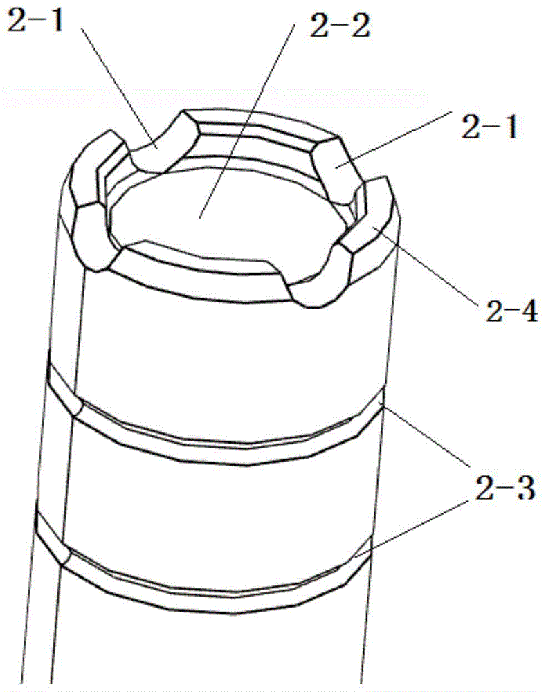
图1所示为柱塞的上端结构示意图;Figure 1 shows a schematic diagram of the upper end structure of the plunger;
图2所示为柱塞的结构示意图;Figure 2 shows a schematic structural diagram of a plunger;
图3所示为快速响应电控喷油器控制阀的剖面结构示意图;Figure 3 shows a schematic cross-sectional structure diagram of a fast-response electronically-controlled injector control valve;
图4所示为控制体的剖面结构示意图。FIG. 4 is a schematic cross-sectional structure diagram of the control body.
图中:1-控制体,1-1-第二喇叭口,1-2-密封锥面,1-3-第一导流段,1-4-出油节流孔,1-5-第二导流段,1-6-第三喇叭口,1-7-控制腔,1-8-柱塞段,1-9-第一喇叭口,1-10-进油节流孔,2-柱塞本体,2-1-径向槽,2-2-沉孔,2-3-环形槽,2-4-凸起,3-球阀。In the figure: 1-control body, 1-1-second bell mouth, 1-2-seal cone, 1-3-first diversion section, 1-4-oil outlet orifice, 1-5-th Second guide section, 1-6-Third bell mouth, 1-7-Control chamber, 1-8-Plunger section, 1-9-First bell mouth, 1-10-Oil inlet orifice, 2- Plunger body, 2-1-radial groove, 2-2-counter hole, 2-3-annular groove, 2-4-protrusion, 3-ball valve.
具体实施方式Detailed ways
以下结合具体实施例对本发明作进一步详细说明。应当理解,此处所描述的具体实施例仅仅用以解释本发明,并不用于限定本发明。The present invention will be further described in detail below in conjunction with specific embodiments. It should be understood that the specific embodiments described herein are only used to explain the present invention, but not to limit the present invention.
实施例1Example 1
一种快速响应电控喷油器控制阀用柱塞,如图1和图2所示,所述柱塞本体2顶端上表面的中部轴向向下凹陷形成沉孔2-2,顶端上表面的外周形成凸起2-4,所述凸起2-4上设置有一个或多个供高压燃油通过的径向槽2-1,每一所述径向槽2-1与所述沉孔2-2在径向上贯通。A plunger for a fast-response electronically controlled fuel injector control valve, as shown in Figures 1 and 2, the middle part of the upper surface of the top of the
柱塞本体2上设置有沉孔2-2和径向槽2-1,使得柱塞上行至上止点,高压燃油通过径向槽2-1和沉孔2-2后由出油通道流出,不影响控制腔内压力的变化,避免柱塞到达上止点时发生震颤。同时,当球阀下行时,高压燃油压力作用在沉孔下表面,柱塞迅速下行,避免了燃油喷射关闭延迟。The
作为优选,所述径向槽2-1为4个,均匀分布在所述凸起2-4上,相邻径向槽2-1的轴线夹角为90°。Preferably, there are four radial grooves 2-1, which are evenly distributed on the protrusions 2-4, and the included angle between the axes of adjacent radial grooves 2-1 is 90°.
作为优选,每一所述径向槽2-1在柱塞的周向方向上的截面为开口向上的半圆形,所述沉孔2-2的高度等于所述半圆形的半径。Preferably, the cross section of each of the radial grooves 2-1 in the circumferential direction of the plunger is a semicircle with an upward opening, and the height of the counterbore 2-2 is equal to the radius of the semicircle.
作为优选,所述沉孔2-2的直径为所述柱塞本体2的直径的70%-95%,使其具有较大的下表面作为受力面,在燃油压力升高时驱动柱塞本体2迅速下行。Preferably, the diameter of the counterbore 2-2 is 70%-95% of the diameter of the
作为优选,所述柱塞本体2的外壁上设置有两个平行的环形槽2-3,每一环形槽2-3为形成在侧壁上的周向槽。该环形槽2-3可以储存控制腔1-7泄露的高压燃油,并在柱塞本体2的外壁与柱塞段1-8内壁形成均匀油膜,减少磨损。Preferably, two parallel annular grooves 2-3 are provided on the outer wall of the
实施例2Example 2
一种快速响应电控喷油器控制阀,如图3所示,包括控制体1、实施例1中所述的柱塞本体2和球阀3;A fast-response electronically controlled fuel injector control valve, as shown in Figure 3, includes a
如图4所示,所述控制体1上设置有供高压燃油进入的进油通道、供高压燃油流出的出油通道和用于容纳所述柱塞本体2的柱塞腔,所述柱塞本体2在所述柱塞腔内上下移动,所述球阀3与所述出油通道线密封,所述进油通道和所述出油通道分别与所述柱塞腔连通;As shown in FIG. 4 , the
所述柱塞腔包括上下设置的控制腔1-7和柱塞段1-8,所述控制腔1-7的直径大于所述柱塞段1-8的直径,所述柱塞段1-8的直径等于所述柱塞本体2的直径,当所述柱塞本体2上行至上止点时,所述柱塞本体2的端部侧面与所述控制腔1-7内侧壁之间形成空隙,为柱塞本体2上行至上止点时,高压燃油提供流动空间;The plunger cavity includes a control cavity 1-7 and a plunger segment 1-8 arranged up and down, the diameter of the control cavity 1-7 is larger than that of the plunger segment 1-8, and the plunger segment 1- The diameter of 8 is equal to the diameter of the
所述柱塞本体2顶端上表面中部轴向向下凹陷形成沉孔2-2,所述柱塞本体2顶端径向设置有供高压燃油通过的径向槽2-1,所述径向槽2-1将所述沉孔2-2与所述柱塞本体2外表面径向贯通。The middle part of the upper surface of the top of the
上述快速响应电控喷油器控制阀的控制方法:The control method of the above-mentioned fast-response electronically controlled injector control valve:
高压燃油通过进油通道进入控制腔1-7,当所述球阀3上行时,所述球阀3与所述出油通道线密封解除,高压燃油通过出油通道流出,由于所述出油节流孔1-4的直径大于所述进油节流孔1-10的直径,所述控制腔1-7内压力降低,柱塞本体2上行至上止点,高压燃油通过柱塞本体2的端部侧面与控制腔1-7内侧壁之间的空隙进入所述径向槽2-1和所述沉孔2-2,后由所述出油通道流出,高压燃油流动通道依旧顺畅,而不影响所述控制腔1-7内压力的变化,避免所述柱塞本体2到达上止点时发生震颤;The high-pressure fuel enters the control chambers 1-7 through the oil inlet channel. When the
当所述球阀3下行时,所述球阀3与所述出油通道线密封建立,所述出油通道关闭,所述控制腔1-7内压力升高,高压燃油压力作用在所述沉孔2-2下表面,驱动所述柱塞本体2迅速下行,避免了燃油喷射关闭延迟。When the
实施例3Example 3
本实施例是在实施例1的基础上对进油通道和出油通道的进一步阐述。This embodiment is a further description of the oil inlet passage and the oil outlet passage on the basis of
具体来说,所述进油通道包括开设在所述控制体1侧面上的第一喇叭口1-9和将所述第一喇叭口1-9和所述控制腔1-7径向贯通的进油节流孔1-10。Specifically, the oil inlet channel includes a first bell mouth 1-9 opened on the side surface of the
具体来说,所述出油通道自上而下依次包括开口向上的第二喇叭口1-1、上大下小的密封锥面1-2、第一导流段1-3、出油节流孔1-4、第二导流段1-5和第三喇叭口1-6;所述球阀3的直径小于所述密封锥面1-2上边缘直径,大于所述第一导流段1-3的直径,即所述密封锥面1-2下边缘直径,所述球阀3与所述密封锥面1-2线密封,所述第三喇叭口1-6开口向下与所述控制腔1-7连通。Specifically, from top to bottom, the oil outlet channel includes a second bell mouth 1-1 with an upward opening, a sealing cone surface 1-2 with a large upper and a small bottom, a first guide section 1-3, and an oil outlet section. Orifice 1-4, second diversion section 1-5 and third bell mouth 1-6; the diameter of the
具体来说,所述出油节流孔1-4的直径大于所述进油节流孔1-10的直径。当所述球阀3上行时,所述球阀3与所述出油通道线密封解除,高压燃油通过出油通道流出,由于所述出油节流孔1-4的直径大于所述进油节流孔1-10的直径,所述控制腔1-7内压力降低。Specifically, the diameter of the oil outlet orifice 1-4 is larger than the diameter of the oil inlet orifice 1-10. When the
以上所述仅是本发明的优选实施方式,应当指出的是,对于本技术领域的普通技术人员来说,在不脱离本发明原理的前提下,还可以做出若干改进和润饰,这些改进和润饰也应视为本发明的保护范围。The above are only the preferred embodiments of the present invention. It should be noted that, for those skilled in the art, without departing from the principles of the present invention, several improvements and modifications can be made. These improvements and Retouching should also be considered within the scope of protection of the present invention.
Claims (10)
Priority Applications (1)
| Application Number | Priority Date | Filing Date | Title |
|---|---|---|---|
| CN202010464265.2A CN111648893A (en) | 2020-05-27 | 2020-05-27 | A plunger for an electronically controlled fuel injector control valve, a fast response electronically controlled fuel injector control valve and a control method thereof |
Applications Claiming Priority (1)
| Application Number | Priority Date | Filing Date | Title |
|---|---|---|---|
| CN202010464265.2A CN111648893A (en) | 2020-05-27 | 2020-05-27 | A plunger for an electronically controlled fuel injector control valve, a fast response electronically controlled fuel injector control valve and a control method thereof |
Publications (1)
| Publication Number | Publication Date |
|---|---|
| CN111648893A true CN111648893A (en) | 2020-09-11 |
Family
ID=72344661
Family Applications (1)
| Application Number | Title | Priority Date | Filing Date |
|---|---|---|---|
| CN202010464265.2A Pending CN111648893A (en) | 2020-05-27 | 2020-05-27 | A plunger for an electronically controlled fuel injector control valve, a fast response electronically controlled fuel injector control valve and a control method thereof |
Country Status (1)
| Country | Link |
|---|---|
| CN (1) | CN111648893A (en) |
Citations (13)
| Publication number | Priority date | Publication date | Assignee | Title |
|---|---|---|---|---|
| GB417541A (en) * | 1933-01-04 | 1934-10-08 | Paul Hansen | Improvements in and relating to fuel injection pumps for internal combustion engines |
| US5011082A (en) * | 1989-03-03 | 1991-04-30 | Weber S.R.L. | Perfected diesel engine electromagnetic fuel injector |
| CN1651753A (en) * | 2004-02-04 | 2005-08-10 | 罗伯特·博世有限公司 | Fuel injection system for IC engine |
| US20050199753A1 (en) * | 2001-05-08 | 2005-09-15 | Peter Boehland | Fuel injection valve for internal combustion engines |
| CN101338716A (en) * | 2008-09-02 | 2009-01-07 | 北京华威奇燃油喷射科技有限公司 | High pressure co-rail electric control fuel injector |
| CN101769217A (en) * | 2008-12-29 | 2010-07-07 | C.R.F.阿西安尼顾问公司 | Fuel injection system with high repeatability and stability of operation for an internal-combustion engine |
| US20100176222A1 (en) * | 2009-01-12 | 2010-07-15 | Gm Global Technology Operations, Inc. | Pressure Actuated Fuel Injector |
| CN102400825A (en) * | 2011-12-20 | 2012-04-04 | 余姚市舒春机械有限公司 | Marine Diesel Engine Cooling Needle Valve Couple |
| CN202937389U (en) * | 2012-10-12 | 2013-05-15 | 福建省莆田市中涵机动力有限公司 | Pressure balanced type outer seal plane control valve of common-rail oil spraying device |
| CN103967666A (en) * | 2013-02-04 | 2014-08-06 | 辽宁新风企业集团有限公司 | Hydraulic controller of center hole pressure accumulation type common rail fuel injector |
| CN104265530A (en) * | 2014-07-31 | 2015-01-07 | 中国第一汽车股份有限公司无锡油泵油嘴研究所 | Injector control valve of electric control internal combustion engine |
| US20150107560A1 (en) * | 2012-05-30 | 2015-04-23 | Caterpillar Motoren Gmbh & Co. Kg | Plunger for an internal combustion engine fuel pump |
| CN109162846A (en) * | 2018-07-26 | 2019-01-08 | 哈尔滨工程大学 | Pressure accumulation type piezoelectricity with control chamber sliding block-electromagnetism bivalve electric-controlled fuel injector |
-
2020
- 2020-05-27 CN CN202010464265.2A patent/CN111648893A/en active Pending
Patent Citations (13)
| Publication number | Priority date | Publication date | Assignee | Title |
|---|---|---|---|---|
| GB417541A (en) * | 1933-01-04 | 1934-10-08 | Paul Hansen | Improvements in and relating to fuel injection pumps for internal combustion engines |
| US5011082A (en) * | 1989-03-03 | 1991-04-30 | Weber S.R.L. | Perfected diesel engine electromagnetic fuel injector |
| US20050199753A1 (en) * | 2001-05-08 | 2005-09-15 | Peter Boehland | Fuel injection valve for internal combustion engines |
| CN1651753A (en) * | 2004-02-04 | 2005-08-10 | 罗伯特·博世有限公司 | Fuel injection system for IC engine |
| CN101338716A (en) * | 2008-09-02 | 2009-01-07 | 北京华威奇燃油喷射科技有限公司 | High pressure co-rail electric control fuel injector |
| CN101769217A (en) * | 2008-12-29 | 2010-07-07 | C.R.F.阿西安尼顾问公司 | Fuel injection system with high repeatability and stability of operation for an internal-combustion engine |
| US20100176222A1 (en) * | 2009-01-12 | 2010-07-15 | Gm Global Technology Operations, Inc. | Pressure Actuated Fuel Injector |
| CN102400825A (en) * | 2011-12-20 | 2012-04-04 | 余姚市舒春机械有限公司 | Marine Diesel Engine Cooling Needle Valve Couple |
| US20150107560A1 (en) * | 2012-05-30 | 2015-04-23 | Caterpillar Motoren Gmbh & Co. Kg | Plunger for an internal combustion engine fuel pump |
| CN202937389U (en) * | 2012-10-12 | 2013-05-15 | 福建省莆田市中涵机动力有限公司 | Pressure balanced type outer seal plane control valve of common-rail oil spraying device |
| CN103967666A (en) * | 2013-02-04 | 2014-08-06 | 辽宁新风企业集团有限公司 | Hydraulic controller of center hole pressure accumulation type common rail fuel injector |
| CN104265530A (en) * | 2014-07-31 | 2015-01-07 | 中国第一汽车股份有限公司无锡油泵油嘴研究所 | Injector control valve of electric control internal combustion engine |
| CN109162846A (en) * | 2018-07-26 | 2019-01-08 | 哈尔滨工程大学 | Pressure accumulation type piezoelectricity with control chamber sliding block-electromagnetism bivalve electric-controlled fuel injector |
Similar Documents
| Publication | Publication Date | Title |
|---|---|---|
| CN104481767B (en) | Common-rail oil injector | |
| CN110529316B (en) | Fuel injection valve and engine | |
| CN109306926B (en) | Valve assembly and check valve for fluid pump | |
| CN103975160B (en) | There is the fuel injector of the pin control system including F, A, Z and E aperture | |
| JPS62228663A (en) | Two-stage hydraulic auxiliary fuel injection nozzle | |
| JPS62107265A (en) | Electrostriction type oil pressure control valve | |
| JP2008531901A (en) | Common rail type injection device having active needle closing means | |
| CN105332826A (en) | Leakage-free electromagnetic-control fuel gas ejection device | |
| JP2003201938A (en) | Fuel injection valve for internal combustion engine | |
| CN111120171B (en) | Fuel injection valve assembly | |
| CN111648893A (en) | A plunger for an electronically controlled fuel injector control valve, a fast response electronically controlled fuel injector control valve and a control method thereof | |
| CN102852686A (en) | A fuel valve for large turbocharged two stroke diesel engines | |
| CN206816400U (en) | A kind of integrated form ring manifold wall gaseous fuel jet mixing device with piezo actuator | |
| CN107120214B (en) | Reverse-preventing integrated annular manifold wall surface gas fuel injection mixing device | |
| CN107131074B (en) | An Integrated Ring Manifold Wall Gas Fuel Injection Mixing Device with Piezoelectric Actuators | |
| CN206860248U (en) | A kind of solenoid-operated hydraulic drive-type fully variable valve actuator for air | |
| CN107120459B (en) | A piezo-electric externally guided gas injection valve with straight-through axial air intake | |
| CN215830689U (en) | Diaphragm type liquid delivery pump with double-sealing structure | |
| CN111878274A (en) | A fuel injection valve and diesel engine | |
| CN206816397U (en) | Fuel gas injection valve is oriented in a kind of piezoelectric type of through type mixed admission | |
| CN107420224A (en) | A kind of integrated form with piezo actuator intersects annular groove gaseous fuel jet mixing device | |
| CN107091171A (en) | A kind of combined electromagnetic piezoelectricity fuel gas injection valve | |
| CN207278383U (en) | A kind of integrated form with piezo actuator intersects annular groove gaseous fuel jet mixing device | |
| CN111535964B (en) | Common rail fuel injector with fast switching function | |
| CN206816401U (en) | Fuel gas injection valve is oriented to outside a kind of piezoelectric type of through type mixed admission |
Legal Events
| Date | Code | Title | Description |
|---|---|---|---|
| PB01 | Publication | ||
| PB01 | Publication | ||
| SE01 | Entry into force of request for substantive examination | ||
| SE01 | Entry into force of request for substantive examination | ||
| RJ01 | Rejection of invention patent application after publication |
Application publication date: 20200911 |
|
| RJ01 | Rejection of invention patent application after publication |