[go: up one dir, main page]

CN111616777B - Minimally invasive scalpel system - Google Patents

Minimally invasive scalpel system Download PDF

Info

Publication number
CN111616777B
CN111616777B CN202010470664.XA CN202010470664A CN111616777B CN 111616777 B CN111616777 B CN 111616777B CN 202010470664 A CN202010470664 A CN 202010470664A CN 111616777 B CN111616777 B CN 111616777B
Authority
CN
China
Prior art keywords
camera
blade
fixedly installed
display screen
seat
Prior art date
Legal status (The legal status is an assumption and is not a legal conclusion. Google has not performed a legal analysis and makes no representation as to the accuracy of the status listed.)
Active
Application number
CN202010470664.XA
Other languages
Chinese (zh)
Other versions
CN111616777A (en
Inventor
胡均
李健
Current Assignee (The listed assignees may be inaccurate. Google has not performed a legal analysis and makes no representation or warranty as to the accuracy of the list.)
Tianjin Medical University Cancer Institute and Hospital
Original Assignee
Individual
Priority date (The priority date is an assumption and is not a legal conclusion. Google has not performed a legal analysis and makes no representation as to the accuracy of the date listed.)
Filing date
Publication date
Application filed by Individual filed Critical Individual
Priority to CN202010470664.XA priority Critical patent/CN111616777B/en
Publication of CN111616777A publication Critical patent/CN111616777A/en
Application granted granted Critical
Publication of CN111616777B publication Critical patent/CN111616777B/en
Active legal-status Critical Current
Anticipated expiration legal-status Critical

Links

Images

Classifications

    • AHUMAN NECESSITIES
    • A61MEDICAL OR VETERINARY SCIENCE; HYGIENE
    • A61BDIAGNOSIS; SURGERY; IDENTIFICATION
    • A61B17/00Surgical instruments, devices or methods
    • A61B17/32Surgical cutting instruments
    • A61B17/3209Incision instruments
    • A61B17/3211Surgical scalpels, knives; Accessories therefor
    • A61B17/3213Surgical scalpels, knives; Accessories therefor with detachable blades
    • AHUMAN NECESSITIES
    • A61MEDICAL OR VETERINARY SCIENCE; HYGIENE
    • A61BDIAGNOSIS; SURGERY; IDENTIFICATION
    • A61B17/00Surgical instruments, devices or methods
    • A61B17/00234Surgical instruments, devices or methods for minimally invasive surgery
    • AHUMAN NECESSITIES
    • A61MEDICAL OR VETERINARY SCIENCE; HYGIENE
    • A61BDIAGNOSIS; SURGERY; IDENTIFICATION
    • A61B90/00Instruments, implements or accessories specially adapted for surgery or diagnosis and not covered by any of the groups A61B1/00 - A61B50/00, e.g. for luxation treatment or for protecting wound edges
    • A61B90/30Devices for illuminating a surgical field, the devices having an interrelation with other surgical devices or with a surgical procedure
    • AHUMAN NECESSITIES
    • A61MEDICAL OR VETERINARY SCIENCE; HYGIENE
    • A61BDIAGNOSIS; SURGERY; IDENTIFICATION
    • A61B90/00Instruments, implements or accessories specially adapted for surgery or diagnosis and not covered by any of the groups A61B1/00 - A61B50/00, e.g. for luxation treatment or for protecting wound edges
    • A61B90/36Image-producing devices or illumination devices not otherwise provided for
    • A61B90/37Surgical systems with images on a monitor during operation
    • AHUMAN NECESSITIES
    • A61MEDICAL OR VETERINARY SCIENCE; HYGIENE
    • A61BDIAGNOSIS; SURGERY; IDENTIFICATION
    • A61B90/00Instruments, implements or accessories specially adapted for surgery or diagnosis and not covered by any of the groups A61B1/00 - A61B50/00, e.g. for luxation treatment or for protecting wound edges
    • A61B90/30Devices for illuminating a surgical field, the devices having an interrelation with other surgical devices or with a surgical procedure
    • A61B2090/309Devices for illuminating a surgical field, the devices having an interrelation with other surgical devices or with a surgical procedure using white LEDs
    • AHUMAN NECESSITIES
    • A61MEDICAL OR VETERINARY SCIENCE; HYGIENE
    • A61BDIAGNOSIS; SURGERY; IDENTIFICATION
    • A61B90/00Instruments, implements or accessories specially adapted for surgery or diagnosis and not covered by any of the groups A61B1/00 - A61B50/00, e.g. for luxation treatment or for protecting wound edges
    • A61B90/36Image-producing devices or illumination devices not otherwise provided for
    • A61B90/37Surgical systems with images on a monitor during operation
    • A61B2090/371Surgical systems with images on a monitor during operation with simultaneous use of two cameras

Landscapes

  • Health & Medical Sciences (AREA)
  • Surgery (AREA)
  • Life Sciences & Earth Sciences (AREA)
  • Nuclear Medicine, Radiotherapy & Molecular Imaging (AREA)
  • Heart & Thoracic Surgery (AREA)
  • Veterinary Medicine (AREA)
  • Engineering & Computer Science (AREA)
  • Biomedical Technology (AREA)
  • Public Health (AREA)
  • Medical Informatics (AREA)
  • Molecular Biology (AREA)
  • Animal Behavior & Ethology (AREA)
  • General Health & Medical Sciences (AREA)
  • Oral & Maxillofacial Surgery (AREA)
  • Pathology (AREA)
  • Gynecology & Obstetrics (AREA)
  • Radiology & Medical Imaging (AREA)
  • Surgical Instruments (AREA)

Abstract

本发明公开了一种微创手术刀系统,包括支撑板,支撑板表面的顶部固定安装有主显示屏,支撑板表面的底部固定安装有置物槽,置物槽内的两侧均固定设有卡条,且置物槽的内部通过卡条卡合安装有手术刀体,手术刀体由刀柄、刀身、刀座、第一刀头和第二刀头组成,本发明手术刀系统刀身上安装有与第二摄像头连接的副显示屏,配合与第一摄像头连接的显示屏构成双屏显示,且第一摄像头和第二摄像头分别从局部和细节处进行观测,使用效果更好,刀座一端同时设有第一刀头和第二刀头,可自由切换配合使用保证手术效果,同时第二刀头顶端设有弧形刀片,侧面开设有带有斜形刀片的切割槽口,可进行多种角度切割和处理伤口,使用更加便捷。

Figure 202010470664

The invention discloses a minimally invasive scalpel system, comprising a support plate, a main display screen is fixedly installed on the top of the surface of the support plate, a storage slot is fixedly installed at the bottom of the surface of the support plate, and clips are fixed on both sides of the storage slot The inside of the storage slot is installed with a scalpel body through clamping strips. The scalpel body is composed of a handle, a blade body, a blade seat, a first blade head and a second blade head. The blade body of the scalpel system of the present invention is installed with a The secondary display screen connected with the second camera cooperates with the display screen connected with the first camera to form a dual-screen display, and the first camera and the second camera are observed from local and detailed points respectively, and the use effect is better. There is a first cutter head and a second cutter head, which can be freely switched and used to ensure the surgical effect. At the same time, the top of the second cutter head is provided with an arc-shaped blade, and the side is provided with a cutting notch with an oblique blade, which can perform various operations. Angled cutting and wound treatment, more convenient to use.

Figure 202010470664

Description

Minimally invasive scalpel system
Technical Field
The invention relates to the field of engines, in particular to a minimally invasive scalpel system.
Background
Minimally invasive surgery is favored due to its advantages of small trauma, low pain, and rapid recovery, but is currently limited in many clinical fields by the lack of instrument assistance and thus cannot be performed well. Especially when carrying out minimal access surgery, after the scalpel gets into the human body, can only rely on doctor's self to judge and operate, lack effective observation measure, be unfavorable for the application popularization of minimal access surgery, current scalpel that has camera device can directly derive the screen of outside with the wound condition of inside, conveniently look over, the supplementary enlargies in the slight department of cutting wound of outside screen, be convenient for observe, but do not assist with the help of the outside screen usually when cutting other positions, the doctor directly operates, but has certain hidden danger problem like this.
Meanwhile, the incision of the open surgery is large, the large incision can cause damage to muscles, blood vessels and corresponding nerves near the incision, and certain tissue infection complications can be accompanied, so that the recovery speed of a patient is slow.
Disclosure of Invention
The present invention is directed to a minimally invasive scalpel system, which solves the above problems of the prior art.
In order to achieve the purpose, the invention provides the following technical scheme: the utility model provides a minimal access surgery sword system, includes the backup pad, the top fixed mounting on backup pad surface has the main display screen, the bottom fixed mounting on backup pad surface has puts the thing groove, the both sides of putting the thing inslot all have the card strip through conical support fixed mounting, just put the inside of thing groove and install the operation cutter body through card strip block, the operation cutter body comprises handle of a knife, blade holder, first tool bit, second tool bit, first camera, second camera, main display screen and vice display screen, the sliding chamber has been seted up to the inside of handle of a knife, the inside sliding connection in sliding chamber has the blade, the one end fixedly connected with blade holder of blade, the one end fixedly connected with second tool bit of blade holder, the bottom mounting of second tool bit is equipped with first tool bit, the fixed cutting seat that is equipped with of one end of second tool bit.
Preferably, a piston cavity is formed in the second cutter head, a piston is slidably sleeved in the piston cavity, and a piston rod is fixedly connected to one side of the piston.
Preferably, a cutting notch is formed in the side face of the end of the cutting seat, oblique blades are fixedly mounted on two sides of the inner wall of the cutting notch, the two oblique blades are symmetrically arranged at the edge of the cutting end, a camera support is fixedly mounted at the bottom of the cutting notch, a first camera is fixedly mounted inside the camera support, an inner groove is formed in the end of the cutting seat, and an arc-shaped blade is fixedly mounted at the bottom of the inner groove.
Preferably, a mounting groove is formed in one side of the second tool bit, a plurality of fixing plates are fixedly mounted in the mounting groove through fixing bolts, and the bottom ends of the fixing plates are fixedly connected with the top end of the first tool bit.
Preferably, interior chamber has been seted up to the one end of blade, the arc wall has been seted up to the bottom in the interior chamber, the inside sliding connection of arc wall has the slider, the bottom fixed connection of the top of slider and mount pad, the installation room has been seted up to the inside of mount pad, the inside fixed mounting of installation room has wireless transmitter, second camera and light source, just wireless transmitter's both sides are arranged respectively in to second camera and light source, the opposite side fixedly connected with spring of mount pad, just the fixed cover in inside of spring is equipped with the push rod, the branch fixed connection at interior chamber and blade top is run through to the one end of push rod.
Preferably, there is a tooth section of thick bamboo one side at blade holder top through pivot movable mounting, the cavity has been seted up to the inside of blade holder, the spout has been seted up to the bottom in the cavity, the inside sliding connection of spout has a plurality of slide bars, and is a plurality of the top of slide bar all is connected with the bottom fixed connection of pinion rack, just the top of pinion rack is connected with the bottom meshing of a tooth section of thick bamboo, the one end and the piston rod fixed connection of pinion rack.
Preferably, the other end fixed mounting of blade has vice display screen, the metallic channel has been seted up to the blade bottom, the inside fixed mounting of metallic channel has waterproof rubber tube, the inside fixed mounting of waterproof rubber tube has the wire, vice display screen passes through wire electric connection with the second camera, the equal threaded connection in both ends of handle of a knife has the dead lever, the one end of dead lever runs through handle of a knife and the inside fixed disk fixed connection of handle of a knife, the fixed cover of the other end of dead lever is equipped with the lag, the mounting groove has been seted up to one side at handle of a knife top, the inside fixed mounting of mounting groove has transparent protective glass, just it has the foam cushion to fill between the inner wall of transparent protective glass and mounting groove.
Preferably, the handle grooves are formed in the two sides of the supporting plate, the controller and the wireless receiver are fixedly mounted inside the supporting plate, the light source is an LED lamp, the controller is electrically connected with the wireless receiver, the main display screen and the LED lamp respectively, and the wireless transmitter is electrically connected with the first camera.
The invention has the technical effects and advantages that:
(1) install the vice display screen of being connected with the second camera on the blade, the cooperation constitutes double-screen display with the main display screen that first camera is connected, has both avoided doctor's fatigue operation to lead to the error problem, and is more handy during operation of doctor simultaneously, and first camera and second camera are followed part and detail respectively and are surveyd, and the result of use is better.
(2) Blade holder one end is equipped with first tool bit and second tool bit simultaneously, can freely switch the cooperation and use and guarantee the operation effect, and second tool bit top is equipped with the arc blade simultaneously, and the cutting notch that has the oblique shape blade is seted up to the side, can carry out multiple angle cutting and handle the wound, and it is more convenient to use.
Drawings
FIG. 1 is a schematic view of the structure of the surgical knife body of the present invention;
FIG. 2 is an enlarged schematic view of the support plate of the present invention;
FIG. 3 is an enlarged view of the arc-shaped slot of the present invention;
FIG. 4 is a schematic view of a second tool tip of the present invention;
FIG. 5 is a schematic view of the structure of the internal chamber of the present invention;
FIG. 6 is a schematic view of the piston of the present invention;
FIG. 7 is an enlarged schematic view of the arcuate blade of the present invention;
fig. 8 is a schematic view of an electrical connection structure of the first camera according to the present invention.
In the figure: 1. a support plate; 2. a main display screen; 3. a storage groove; 4. a handle slot; 5. clamping the strip; 6. a surgical knife body; 7. a knife handle; 8. a blade body; 9. transparent protective glass; 10. a secondary display screen; 11. a tool apron; 12. a first cutter head; 13. a fixing plate; 14. a second cutter head; 15. a fixing bolt; 16. an arc-shaped blade; 17. a beveled blade; 18. an inner tank; 19. cutting a notch; 20. a first camera; 21. an inner chamber; 22. an arc-shaped slot; 23. a slider; 24. a mounting seat; 25. a wireless transmitter; 26. a second camera; 27. a light source; 28. a toothed plate; 29. a gear cylinder; 30. a push rod; 31. a spring; 32. a piston; 33. a piston rod; 34. mounting grooves; 35. and (4) cutting the base.
Detailed Description
The technical solutions in the embodiments of the present invention will be clearly and completely described below with reference to the drawings in the embodiments of the present invention, and it is obvious that the described embodiments are only a part of the embodiments of the present invention, and not all of the embodiments. All other embodiments, which can be derived by a person skilled in the art from the embodiments given herein without making any creative effort, shall fall within the protection scope of the present invention.
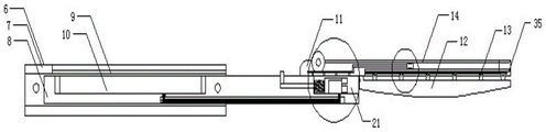
The invention provides a minimally invasive scalpel system as shown in figures 1-8, which comprises a supporting plate 1, wherein a main display screen 2 is fixedly arranged at the top of the surface of the supporting plate 1, an object placing groove 3 is fixedly arranged at the bottom of the surface of the supporting plate 1, clamping strips 5 are fixedly arranged on two sides in the object placing groove 3, a scalpel body 6 is clamped and arranged in the object placing groove 3 through the clamping strips 5, the scalpel body 6 consists of a scalpel handle 7, a scalpel body 8, a scalpel base 11, a first scalpel head 12 and a second scalpel head 14, a sliding cavity is formed in the scalpel handle 7, the scalpel body 8 is slidably connected in the sliding cavity, the scalpel base 11 is fixedly connected at one end of the scalpel body 8, the second scalpel head 14 is fixedly connected at one end of the scalpel base 11, the first scalpel head 12 is fixedly arranged at the bottom end of the second scalpel head 14, the end of the second scalpel head 14 is pressed at a diseased region, and when the diseased region is adsorbed, arc blade 16 on the inside groove 18 cuts, switch into cutting notch 19 with second tool bit 14 simultaneously and use, after handling for the first time, the pathological change wound still has the residue, can aim at pathological change position with cutting notch 19, treat that pathological change position adsorbs the back that gets into, rotate blade 8, cut through oblique blade 17 on the cutting notch 19, promote branch, branch drives mount pad 24 and slides through slider 23, when sliding to the segmental arc of arc 22, mount pad 24 changes the angle, thereby make its inside second camera 26 change the angle, be convenient for whole observation more.
The piston chamber has been seted up to the inside of second tool bit 14, and the inside slip cover in piston chamber is equipped with piston 32, and one side fixedly connected with piston rod 33 of piston 32 stimulates piston rod 33, drives piston 32 motion, forms the negative pressure at the piston intracavity portion to make the pathological change position that second tool bit 14 cut down adsorbed inside second tool bit 14, reduced the burden of wound clearance.
The side of the end of the second cutter head 14 is provided with a cutting notch 19, both sides of the inner wall of the cutting notch 19 are fixedly provided with oblique blades 17, the bottom of the cutting notch 19 is fixedly provided with a first camera 20, the end of the second cutter head 14 is provided with an inner groove 18, the bottom of the inner groove 18 is fixedly provided with an arc-shaped blade 16, the end of the second cutter head 14 is pressed on a pathological change part, when the pathological change part is adsorbed inside the second cutter head 14, the second cutter head 14 is rotated, the arc-shaped blade 16 on the inner groove 18 is used, meanwhile, the second cutter head 14 is switched into the cutting notch 19 for use, after the first treatment, a pathological change wound still remains, the cutting notch 19 can be aligned to the pathological change part, after the pathological change part is adsorbed and enters, the cutter body 8 is rotated, and cutting is carried out through the oblique blades 17 on.
The mounting groove 34 has been seted up to second tool bit 14 one side, and the inside of mounting groove 34 is through gim peg 15 fixed mounting has a plurality of fixed plates 13, and the bottom of a plurality of fixed plates 13 all with the top fixed connection of first tool bit 12, and fixed plate 13 is fixed first tool bit 12.
Interior chamber 21 has been seted up to blade 8's one end, arc 22 has been seted up to the bottom in interior chamber 21, the inside sliding connection of arc 22 has slider 23, the top of slider 23 and the bottom fixed connection of mount pad 24, the inside fixed mounting of mount pad 24 has wireless transmitter 25, one side fixed mounting of mount pad 24 has second camera 26 and light source 27, mount pad 24's opposite side fixedly connected with spring 31, and the inside fixed cover of spring 31 is equipped with push rod 30, the one end of push rod 30 runs through the branch fixed connection at interior chamber 21 and blade 8 top, promote branch, branch drives mount pad 24 and slides through slider 23, when sliding to arc 22's segmental arc, mount pad 24 changes the angle, thereby make its inside second camera 26 change the angle, be convenient for whole observation more.
One side at the top of the tool apron 11 is movably provided with a toothed cylinder 29 through a rotating shaft, the inner part of the tool apron 11 is connected with a toothed plate 28 in a sliding manner, the toothed plate 28 is meshed with the bottom end of the toothed cylinder 29, one end of the toothed plate 28 is fixedly connected with a piston rod 33, the toothed cylinder 29 is rotated, the toothed cylinder 29 is meshed with the toothed plate 28, the toothed plate 28 can be driven to slide, and the piston rod 33 is driven to move through the toothed plate 28.
The other end fixed mounting of blade 8 has vice display screen 10, vice display screen 10 and second camera 26 electric connection, and the equal threaded connection in both ends of handle of a knife 7 has the dead lever, and one side fixed mounting at handle of a knife 7 top has transparent cover glass 9, and auxiliary display screen 10 is observed to permeable transparent cover glass 9.
Handle groove 4 has all been seted up to backup pad 1's both sides, backup pad 1's inside fixed mounting has controller and wireless receiver, light source 27 is the LED lamp, the controller respectively with wireless receiver, 2 and LED lamp electric connection are shielded to the main display, wireless transmitter 25 and first camera 20 electric connection, first camera 20 will be observed the audio-video and send into the controller through wireless transmitter 25, the controller receives through wireless receiver, and put in on the main display screen 2, be convenient for carry out the detail show of pathological change position.
The working principle of the invention is as follows: the gear cylinder 29 is rotated, the gear cylinder 29 is meshed with the toothed plate 28, the toothed plate 28 can be driven to slide, the toothed plate 28 drives the piston rod 33 to move, the piston rod 33 is pulled, the piston 32 is driven to move, negative pressure is formed in the cavity of the piston, a lesion part cut by the second cutter head 14 is adsorbed on the second cutter head 14, the burden of wound cleaning is reduced, the end head of the second cutter head 14 is pressed on the lesion part, when the lesion part is adsorbed in the second cutter head 14, the second cutter head 14 is rotated, the arc-shaped blade 16 on the inner groove 18 is cut, the second cutter head 14 is switched into the cutting notch 19 for use, after the first treatment, the lesion wound still remains, the cutting notch 19 can be aligned to the lesion part, after the lesion part is adsorbed, the cutter body 8 is rotated, cutting is carried out through the oblique-shaped blade 17 on the cutting notch 19, the support rod is pushed, the mounting seat 24 is driven by the support rod to slide through the sliding block, when sliding to the arc section of arc wall 22, mount pad 24 changes the angle to make its inside second camera 26 change the angle, be convenient for whole observation more, wireless transmitter 25 and first camera 20 electric connection, first camera 20 will observe the audio-video and send into the controller through wireless transmitter 25, and the controller passes through wireless receiver and receives, and puts in on main display screen 2, is convenient for carry out the detail show of pathological change position.
In the description of the present invention, unless otherwise expressly specified or limited, the terms "disposed," "mounted," "connected," and "secured" are to be construed broadly, e.g., as meaning fixedly connected, detachably connected, or integral to; can be mechanically or electrically connected; either directly or indirectly through intervening media, either internally or in any other relationship. The specific meanings of the above terms in the present invention can be understood in specific cases to those skilled in the art.
The standard parts used by the invention can be purchased from the market, and the special-shaped parts can be customized according to the description and the description of the attached drawings.
Although embodiments of the present invention have been shown and described, it will be appreciated by those skilled in the art that changes, modifications, substitutions and alterations can be made in these embodiments without departing from the principles and spirit of the invention, the scope of which is defined in the appended claims and their equivalents.

Claims (6)

1.一种微创手术刀系统,包括支撑板(1),其特征在于:所述支撑板(1)表面的顶部固定安装有主显示屏(2),所述支撑板(1)表面的底部固定安装有置物槽(3),所述置物槽(3)内的两侧均通过锥形支架固定安装有卡条(5),且所述置物槽(3)的内部通过卡条(5)卡合安装有手术刀体(6),所述手术刀体(6)由刀柄(7)、刀身(8)、刀座(11)、第一刀头(12)、第二刀头(14)、第一摄像头(20)、第二摄像头(26)、主显示屏(2)和副显示屏(10)组成,所述刀柄(7)的内部开设有滑腔,所述滑腔内部滑动连接有刀身(8),所述刀身(8)的一端固定连接有刀座(11),所述刀座(11)的一端固定连接有第二刀头(14),所述第二刀头(14)的底端固定设有第一刀头(12),所述第二刀头(14)的一端固定设有切割座(35);所述第二刀头(14)的内部开设有活塞腔,所述活塞腔的内部滑动套设有活塞(32),所述活塞(32)的一侧固定连接有活塞杆(33);所述切割座(35)端头的侧面开设有切割槽口(19),所述切割槽口(19)内壁的两侧均固定安装有斜形刀片(17),且两个斜形刀片(17)的刀口端对称设置,所述切割槽口(19)内的底部固定安装有摄像头支架,所述摄像头支架的内部固定安装有第一摄像头(20),所述切割座(35)的端头处开设有内槽(18),所述内槽(18)的底部固定安装有弧形刀片(16)。1. A minimally invasive scalpel system, comprising a support plate (1), characterized in that: a main display screen (2) is fixedly installed on the top of the surface of the support plate (1), and a main display screen (2) is fixedly installed on the surface of the support plate (1). A storage slot (3) is fixedly installed at the bottom, and both sides of the storage slot (3) are fixedly installed with clips (5) through tapered brackets, and the interior of the storage slot (3) passes through the clips (5). ) is fitted with a scalpel body (6), the scalpel body (6) consists of a handle (7), a blade body (8), a blade seat (11), a first blade head (12), and a second blade head (14), a first camera (20), a second camera (26), a main display screen (2) and a secondary display screen (10), a sliding cavity is opened inside the handle (7), and the sliding A knife body (8) is slidably connected inside the cavity, one end of the knife body (8) is fixedly connected with a knife seat (11), and one end of the knife seat (11) is fixedly connected with a second knife head (14). The bottom ends of the two cutter heads (14) are fixedly provided with a first cutter head (12), and one end of the second cutter head (14) is fixedly provided with a cutting seat (35); A piston cavity is opened inside, the inner sliding sleeve of the piston cavity is provided with a piston (32), and one side of the piston (32) is fixedly connected with a piston rod (33); the side surface of the end of the cutting seat (35) A cutting notch (19) is provided, both sides of the inner wall of the cutting notch (19) are fixedly installed with oblique blades (17), and the knife edge ends of the two oblique blades (17) are symmetrically arranged, and the cutting A camera bracket is fixedly installed at the bottom of the slot (19), a first camera head (20) is fixedly installed in the inside of the camera bracket, and an inner slot (18) is opened at the end of the cutting seat (35), so An arc-shaped blade (16) is fixedly installed at the bottom of the inner groove (18). 2.根据权利要求1所述的一种微创手术刀系统,其特征在于:所述第二刀头(14)一侧开设有安装槽(34),所述安装槽(34)的内部固定安装有若干固定栓,所述安装槽的内部通过固定栓(15)固定安装有若干固定板,且若干所述固定板的底端均与第一刀头(12)的顶端固定连接。2 . The minimally invasive scalpel system according to claim 1 , wherein a mounting groove ( 34 ) is opened on one side of the second cutter head ( 14 ), and the interior of the mounting groove ( 34 ) is fixed inside. 3 . A plurality of fixing bolts are installed, and a plurality of fixing plates are fixedly installed in the interior of the installation groove through the fixing bolts (15), and the bottom ends of the plurality of fixing plates are all fixedly connected with the top end of the first cutter head (12). 3.根据权利要求1所述的一种微创手术刀系统,其特征在于:所述刀身(8)的一端开设有内腔室(21),所述内腔室(21)内的底部开设有弧形槽(22),所述弧形槽(22)的内部滑动连接有滑块(23),所述滑块(23)的顶端与安装座(24)的底端固定连接,所述安装座(24)的内部开设有安装室,所述安装室的内部固定安装有无线发射器(25)、第二摄像头(26)和光源(27),且所述第二摄像头(26)和光源(27)分别置于无线发射器(25)的两侧,所述安装座(24)的另一侧固定连接有弹簧(31),且所述弹簧(31)的内部固定套设有推杆(30),所述推杆(30)的一端贯穿内腔室(21)与刀身(8)顶部的支杆固定连接。3. A minimally invasive scalpel system according to claim 1, characterized in that: an inner chamber (21) is opened at one end of the blade body (8), and an inner chamber (21) is opened at the bottom of the inner chamber (21) There is an arc-shaped groove (22), the interior of the arc-shaped groove (22) is slidably connected with a slider (23), and the top end of the slider (23) is fixedly connected with the bottom end of the mounting seat (24). An installation room is opened inside the installation seat (24), and a wireless transmitter (25), a second camera (26) and a light source (27) are fixedly installed in the inside of the installation room, and the second camera (26) and The light sources (27) are respectively placed on both sides of the wireless transmitter (25), the other side of the mounting seat (24) is fixedly connected with a spring (31), and the inner fixed sleeve of the spring (31) is provided with a pusher. A rod (30), one end of the push rod (30) penetrates through the inner chamber (21) and is fixedly connected to the support rod on the top of the blade body (8). 4.根据权利要求2所述的一种微创手术刀系统,其特征在于:所述刀座(11)顶部的一侧通过转轴活动安装有齿筒(29),所述刀座(11)的内部开设有空腔,所述空腔内的底部开设有滑槽,所述滑槽的内部滑动连接有若干滑杆,若干所述滑杆的顶端均与齿板(28)的底端固定连接,且所述齿板(28)的顶端与齿筒(29)的底端啮合连接,所述齿板(28)的一端与活塞杆(33)固定连接。4. A minimally invasive scalpel system according to claim 2, characterized in that a gear cylinder (29) is movably installed on one side of the top of the knife seat (11) through a rotating shaft, and the knife seat (11) A cavity is opened inside the cavity, a chute is opened at the bottom of the cavity, a number of sliding bars are slidably connected to the inside of the chute, and the tops of the sliding bars are fixed with the bottom end of the toothed plate (28). The top end of the toothed plate (28) is engaged with the bottom end of the toothed cylinder (29), and one end of the toothed plate (28) is fixedly connected with the piston rod (33). 5.根据权利要求1所述的一种微创手术刀系统,其特征在于:所述刀身(8)的另一端固定安装有副显示屏(10),所述刀身(8)底端开设有导线槽,所述导线槽的内部固定安装有防水橡胶管,所述防水橡胶管的内部固定安装有导线,所述副显示屏(10)与第二摄像头(26)通过导线电性连接,所述刀柄(7)的两端均螺纹连接有固定杆,所述固定杆的一端贯穿刀柄(7)与刀柄(7)内部的固定盘固定连接,所述固定杆的另一端固定套设有防护套,所述刀柄(7)顶部的一侧开设有安装槽,所述安装槽的内部固定安装有透明防护玻璃(9),且所述透明防护玻璃(9)与安装槽的内壁之间填充有泡棉胶垫。5 . The minimally invasive scalpel system according to claim 1 , wherein a secondary display screen ( 10 ) is fixedly installed at the other end of the blade body ( 8 ), and a bottom end of the blade body ( 8 ) is provided with a A wire trough, a waterproof rubber tube is fixedly installed inside the wire trough, a wire is fixedly installed inside the waterproof rubber tube, and the secondary display screen (10) and the second camera (26) are electrically connected through the wire, so Both ends of the handle (7) are threadedly connected with a fixing rod, one end of the fixing rod penetrates the handle (7) and is fixedly connected with the fixing plate inside the handle (7), and the other end of the fixing rod is fixed with a sleeve A protective sleeve is provided, a mounting groove is opened on one side of the top of the handle (7), a transparent protective glass (9) is fixedly installed in the interior of the mounting groove, and the transparent protective glass (9) is connected to the mounting groove. A foam pad is filled between the inner walls. 6.根据权利要求3所述的一种微创手术刀系统,其特征在于:所述支撑板(1)的两侧均开设有把手槽(4),所述支撑板(1)的内部固定安装有控制器和无线接收器,所述光源(27)为LED灯,所述控制器分别与无线接收器、主显示屏(2)和LED灯电性连接,所述无线发射器(25)与第一摄像头(20)电性连接。6 . The minimally invasive scalpel system according to claim 3 , characterized in that: both sides of the support plate ( 1 ) are provided with handle grooves ( 4 ), and the interior of the support plate ( 1 ) is fixed inside. 7 . A controller and a wireless receiver are installed, the light source (27) is an LED lamp, the controller is electrically connected to the wireless receiver, the main display screen (2) and the LED lamp respectively, the wireless transmitter (25) It is electrically connected with the first camera (20).
CN202010470664.XA 2020-05-28 2020-05-28 Minimally invasive scalpel system Active CN111616777B (en)

Priority Applications (1)

Application Number Priority Date Filing Date Title
CN202010470664.XA CN111616777B (en) 2020-05-28 2020-05-28 Minimally invasive scalpel system

Applications Claiming Priority (1)

Application Number Priority Date Filing Date Title
CN202010470664.XA CN111616777B (en) 2020-05-28 2020-05-28 Minimally invasive scalpel system

Publications (2)

Publication Number Publication Date
CN111616777A CN111616777A (en) 2020-09-04
CN111616777B true CN111616777B (en) 2021-04-13

Family

ID=72267745

Family Applications (1)

Application Number Title Priority Date Filing Date
CN202010470664.XA Active CN111616777B (en) 2020-05-28 2020-05-28 Minimally invasive scalpel system

Country Status (1)

Country Link
CN (1) CN111616777B (en)

Families Citing this family (2)

* Cited by examiner, † Cited by third party
Publication number Priority date Publication date Assignee Title
CN112842477B (en) * 2020-12-31 2021-11-02 邓娅莉 A breast hyperplasia detection and excision device
CN113288016B (en) * 2021-05-31 2022-07-12 甘肃省人民医院 Robot operating system for wound treatment

Citations (4)

* Cited by examiner, † Cited by third party
Publication number Priority date Publication date Assignee Title
CN204446282U (en) * 2015-02-03 2015-07-08 南阳医学高等专科学校第一附属医院 A kind of ophthalmic scalpel
CN107789018A (en) * 2016-08-30 2018-03-13 重庆西山科技股份有限公司 Medical reciprocating knife tool
CN207545164U (en) * 2017-03-22 2018-06-29 上海交通大学医学院附属第九人民医院 A kind of integrated interventional treatment system of soft tissue release visualization
WO2019089307A1 (en) * 2017-10-30 2019-05-09 Ethicon Llc Surgical instruments comprising a system for articulation and rotation compensation

Family Cites Families (4)

* Cited by examiner, † Cited by third party
Publication number Priority date Publication date Assignee Title
CN2855347Y (en) * 2005-09-20 2007-01-10 钟李宽 Controller of digital code plasma coagulotomy blade
CA2768129C (en) * 2009-07-15 2017-11-28 Ethicon Endo-Surgery, Inc. Electrosurgery generator for ultrasonic surgical instruments
CN102038544B (en) * 2009-10-19 2012-05-23 上海贝奥路生物材料有限公司 Underrun scraper for treating aseptic femoral head necrosis
US11547815B2 (en) * 2018-05-30 2023-01-10 Covidien Lp Systems and methods for measuring and controlling pressure within an internal body cavity

Patent Citations (4)

* Cited by examiner, † Cited by third party
Publication number Priority date Publication date Assignee Title
CN204446282U (en) * 2015-02-03 2015-07-08 南阳医学高等专科学校第一附属医院 A kind of ophthalmic scalpel
CN107789018A (en) * 2016-08-30 2018-03-13 重庆西山科技股份有限公司 Medical reciprocating knife tool
CN207545164U (en) * 2017-03-22 2018-06-29 上海交通大学医学院附属第九人民医院 A kind of integrated interventional treatment system of soft tissue release visualization
WO2019089307A1 (en) * 2017-10-30 2019-05-09 Ethicon Llc Surgical instruments comprising a system for articulation and rotation compensation

Also Published As

Publication number Publication date
CN111616777A (en) 2020-09-04

Similar Documents

Publication Publication Date Title
CN109498070B (en) Multipoint biopsy sampling device for breast tumor minimally invasive surgery
CN111616777B (en) Minimally invasive scalpel system
CN110680411B (en) A kind of cervical needle biopsy forceps and using method thereof
CN112656469A (en) Rapid limiting device and rapid limiting method for laparoscopic surgery wound suturing
CN115349922B (en) High-efficient antibacterial wicresoft great saphenous vein collection system
CN110327085B (en) Auxiliary device for abdominal operation
CN109567878B (en) Marrow aspiration biopsy device
CN205215509U (en) Multifunctional ophthalmic scalpel
CN113509241B (en) Cyst surgical cutter for dermatology department
CN114098841A (en) Sampling device for dermatology department
CN113974703A (en) Lung cancer tumour sampling device
CN210903280U (en) Detachable puncture outfit
CN118105139A (en) Orthopedic medical ultrasonic cutter
CN212996666U (en) Disposable prepuce cutting anastomat with safety mechanism
CN203662907U (en) Scalpel for general surgery department
CN221154633U (en) Limb fixing device for bone tumor operation patient
CN212939931U (en) Hemostat for hepatobiliary surgery
CN215503730U (en) Scalpel for ophthalmology
CN209404829U (en) A special specimen collector for oral tumors
CN219578981U (en) Puncture device convenient to operation
CN217548178U (en) An easy-to-use device for removing uterine fibroids for gynecological surgery
CN218220543U (en) Operation auxiliary device with adjustable
CN205322473U (en) Backbone veutro baffle with orthopedics coping saw guide function
CN210871740U (en) Skin tissue perforator for general surgery department clinic
CN221205533U (en) Cutting anastomat suitable for minimally invasive surgery

Legal Events

Date Code Title Description
PB01 Publication
PB01 Publication
SE01 Entry into force of request for substantive examination
GR01 Patent grant
GR01 Patent grant
TR01 Transfer of patent right

Effective date of registration: 20230330

Address after: 300381 North Huanhu West Road, Tiyuan, Hexi District, Tianjin City

Patentee after: TIANJIN CANCER HOSPITAL(TIANJIN MEDICAL University CANCERINSTITUTE& Hospital)

Address before: Room 402, door 4, building 21, Rihuali, yingshuidao, Nankai District, Tianjin, 300384

Patentee before: Hu Jun