CN111604096A - A liquid discrete microfluidic chip and method of using the same - Google Patents
A liquid discrete microfluidic chip and method of using the same Download PDFInfo
- Publication number
- CN111604096A CN111604096A CN202010458732.0A CN202010458732A CN111604096A CN 111604096 A CN111604096 A CN 111604096A CN 202010458732 A CN202010458732 A CN 202010458732A CN 111604096 A CN111604096 A CN 111604096A
- Authority
- CN
- China
- Prior art keywords
- liquid
- tank
- reaction tank
- microfluidic chip
- reaction
- Prior art date
- Legal status (The legal status is an assumption and is not a legal conclusion. Google has not performed a legal analysis and makes no representation as to the accuracy of the status listed.)
- Granted
Links
Images


Classifications
-
- B—PERFORMING OPERATIONS; TRANSPORTING
- B01—PHYSICAL OR CHEMICAL PROCESSES OR APPARATUS IN GENERAL
- B01L—CHEMICAL OR PHYSICAL LABORATORY APPARATUS FOR GENERAL USE
- B01L3/00—Containers or dishes for laboratory use, e.g. laboratory glassware; Droppers
- B01L3/50—Containers for the purpose of retaining a material to be analysed, e.g. test tubes
- B01L3/502—Containers for the purpose of retaining a material to be analysed, e.g. test tubes with fluid transport, e.g. in multi-compartment structures
- B01L3/5027—Containers for the purpose of retaining a material to be analysed, e.g. test tubes with fluid transport, e.g. in multi-compartment structures by integrated microfluidic structures, i.e. dimensions of channels and chambers are such that surface tension forces are important, e.g. lab-on-a-chip
-
- B—PERFORMING OPERATIONS; TRANSPORTING
- B01—PHYSICAL OR CHEMICAL PROCESSES OR APPARATUS IN GENERAL
- B01J—CHEMICAL OR PHYSICAL PROCESSES, e.g. CATALYSIS OR COLLOID CHEMISTRY; THEIR RELEVANT APPARATUS
- B01J19/00—Chemical, physical or physico-chemical processes in general; Their relevant apparatus
- B01J19/0093—Microreactors, e.g. miniaturised or microfabricated reactors
-
- B—PERFORMING OPERATIONS; TRANSPORTING
- B01—PHYSICAL OR CHEMICAL PROCESSES OR APPARATUS IN GENERAL
- B01L—CHEMICAL OR PHYSICAL LABORATORY APPARATUS FOR GENERAL USE
- B01L3/00—Containers or dishes for laboratory use, e.g. laboratory glassware; Droppers
- B01L3/50—Containers for the purpose of retaining a material to be analysed, e.g. test tubes
- B01L3/502—Containers for the purpose of retaining a material to be analysed, e.g. test tubes with fluid transport, e.g. in multi-compartment structures
- B01L3/5027—Containers for the purpose of retaining a material to be analysed, e.g. test tubes with fluid transport, e.g. in multi-compartment structures by integrated microfluidic structures, i.e. dimensions of channels and chambers are such that surface tension forces are important, e.g. lab-on-a-chip
- B01L3/502753—Containers for the purpose of retaining a material to be analysed, e.g. test tubes with fluid transport, e.g. in multi-compartment structures by integrated microfluidic structures, i.e. dimensions of channels and chambers are such that surface tension forces are important, e.g. lab-on-a-chip characterised by bulk separation arrangements on lab-on-a-chip devices, e.g. for filtration or centrifugation
-
- B—PERFORMING OPERATIONS; TRANSPORTING
- B01—PHYSICAL OR CHEMICAL PROCESSES OR APPARATUS IN GENERAL
- B01L—CHEMICAL OR PHYSICAL LABORATORY APPARATUS FOR GENERAL USE
- B01L7/00—Heating or cooling apparatus; Heat insulating devices
- B01L7/52—Heating or cooling apparatus; Heat insulating devices with provision for submitting samples to a predetermined sequence of different temperatures, e.g. for treating nucleic acid samples
-
- B—PERFORMING OPERATIONS; TRANSPORTING
- B01—PHYSICAL OR CHEMICAL PROCESSES OR APPARATUS IN GENERAL
- B01L—CHEMICAL OR PHYSICAL LABORATORY APPARATUS FOR GENERAL USE
- B01L2200/00—Solutions for specific problems relating to chemical or physical laboratory apparatus
- B01L2200/10—Integrating sample preparation and analysis in single entity, e.g. lab-on-a-chip concept
Landscapes
- Chemical & Material Sciences (AREA)
- Health & Medical Sciences (AREA)
- Chemical Kinetics & Catalysis (AREA)
- General Health & Medical Sciences (AREA)
- Clinical Laboratory Science (AREA)
- Dispersion Chemistry (AREA)
- Analytical Chemistry (AREA)
- Hematology (AREA)
- Life Sciences & Earth Sciences (AREA)
- Molecular Biology (AREA)
- Organic Chemistry (AREA)
- Biochemistry (AREA)
- Automatic Analysis And Handling Materials Therefor (AREA)
Abstract
Description
技术领域technical field
本发明涉及微流控技术领域,特别是涉及一种液体离散微流控芯片及其使用方法。The invention relates to the technical field of microfluidics, in particular to a liquid discrete microfluidic chip and a method for using the same.
背景技术Background technique
在数字分析检测中,如数字PCR,都需要对样本溶液进行离散化,使得原始样本溶液被拆分成若干个相互独立的反应单元,样本溶液离散化处理在数字分析检测中是极其关键的一个步骤。然而在现有将液体分散填充在微腔室/微孔的技术中,通常技术存在以下缺点:一些液体离散方法操作步骤较为繁琐,一些液体离散方法要求操作人员熟练才能完成较好的液体填充效果,这都将会使得这种液体离散化手段难以集成化和自动化,还会影响分析检测结果。In digital analysis and detection, such as digital PCR, the sample solution needs to be discretized, so that the original sample solution is divided into several independent reaction units. The discrete processing of sample solution is an extremely critical one in digital analysis and detection. step. However, in the existing technology of dispersing and filling liquid in microchambers/micropores, the technology usually has the following disadvantages: some liquid dispersion methods are complicated in operation steps, and some liquid dispersion methods require operators to be skilled in order to achieve better liquid filling effect. , which will make it difficult to integrate and automate this liquid discretization method, and will also affect the analysis and detection results.
因此,现在还有待于开发一种自动化程度高的用于液体离散化的设备。Therefore, it remains to be developed a highly automated apparatus for liquid discretization.
发明内容SUMMARY OF THE INVENTION
本发明的目的在于提出一种用于液体离散化的微流控芯片,所述微流控芯片包括分配单元和液体泵送单元,所述分配单元将第一液体填充入反应槽内的微反应池阵列中,所述液体泵送单元将第二液体传送至所述反应槽内并覆盖所述第一液体,因此,只需要两次加样操作即可快速、有效的实现液体离散化。The purpose of the present invention is to provide a microfluidic chip for liquid discretization, the microfluidic chip includes a distribution unit and a liquid pumping unit, the distribution unit fills the first liquid into the microreaction tank in the reaction tank In the cell array, the liquid pumping unit transmits the second liquid into the reaction tank and covers the first liquid. Therefore, only two sample addition operations are required to quickly and effectively realize liquid discretization.
一方面,本发明提供的一种微流控芯片,包括:On the one hand, a microfluidic chip provided by the present invention includes:
至少一个反应槽,所述反应槽内设置有微反应池阵列,所述微反应池阵列用于填充第一液体;at least one reaction tank, the reaction tank is provided with a micro-reaction pool array, and the micro-reaction pool array is used to fill the first liquid;
至少一个液体泵送单元,与所述反应槽连接,用于将第二液体传送至所述反应槽并覆盖所述第一液体;at least one liquid pumping unit, connected to the reaction tank, for delivering a second liquid to the reaction tank and covering the first liquid;
其中,所述第一液体与第二液体互不相容。Wherein, the first liquid and the second liquid are incompatible with each other.
进一步的,所述液体泵送单元包括:Further, the liquid pumping unit includes:
第二液体槽,用于装载第二液体;the second liquid tank for loading the second liquid;
压缩室,用于装载可压缩介质。Compression chamber for loading compressible media.
进一步的,所述微流控芯片具备旋转中心,所述反应槽、第二液体槽和压缩室与所述旋转中心之间的径向距离依次增大。Further, the microfluidic chip has a rotation center, and the radial distances between the reaction tank, the second liquid tank and the compression chamber and the rotation center increase sequentially.
进一步的,所述第二液体槽的出口连接第一流道,所述压缩室的出口连接第二流道,所述第一流道和所述第二流道相交后与第三流道连接;Further, the outlet of the second liquid tank is connected to the first flow channel, the outlet of the compression chamber is connected to the second flow channel, and the first flow channel and the second flow channel are connected to the third flow channel after intersecting;
所述反应槽的远心端连接有毛细通道,所述第三流道通过所述毛细通道与所述反应槽连接。The distal end of the reaction tank is connected with a capillary channel, and the third flow channel is connected with the reaction tank through the capillary channel.
进一步的,所述第二流道、第三流道和毛细通道的尺寸大于所述第一流道的尺寸。Further, the size of the second flow channel, the third flow channel and the capillary channel is larger than the size of the first flow channel.
进一步的,所述微流控芯片还包括分配单元,用于将第一液体分配至所述反应槽;所述分配单元设置有:Further, the microfluidic chip further includes a distribution unit for distributing the first liquid to the reaction tank; the distribution unit is provided with:
第一液体槽,用于装载第一液体;a first liquid tank for loading the first liquid;
分配通道,首端与所述第一液体槽的出口连接,中段与所述反应槽的近心端连接;a distribution channel, the head end is connected with the outlet of the first liquid tank, and the middle section is connected with the proximal end of the reaction tank;
废液槽,与所述分配通道的末端连接。A waste tank is connected to the end of the distribution channel.
进一步的,所述微流控芯片具备旋转中心,所述第一液体槽、分配通道和反应槽与所述旋转中心之间的径向距离依次增大。Further, the microfluidic chip has a center of rotation, and the radial distances between the first liquid tank, the distribution channel and the reaction tank and the center of rotation increase sequentially.
进一步的,所述微流控芯片还包括毛细通道,所述毛细通道的近心端与所述反应槽的远心端连接,所述毛细通道的远心端与所述液体泵送单元连接;所述毛细通道具有弯曲结构,所述毛细通道与所述旋转中心之间的最短径向距离小于所述反应槽的近心端与所述旋转中心之间的径向距离;所述毛细通道的远心端与所述旋转中心之间的径向距离大于所述反应槽的远心端与所述旋转中心之间的径向距离。Further, the microfluidic chip further includes a capillary channel, the proximal end of the capillary channel is connected with the distal end of the reaction tank, and the distal end of the capillary channel is connected with the liquid pumping unit; The capillary channel has a curved structure, and the shortest radial distance between the capillary channel and the rotation center is smaller than the radial distance between the proximal end of the reaction tank and the rotation center; The radial distance between the distal end and the rotation center is greater than the radial distance between the distal end of the reaction tank and the rotation center.
进一步的,所述毛细通道的内表面经过改性处理,使得其对第一液体的虹吸作用减小而对第二液体的虹吸作用增大。Further, the inner surface of the capillary channel is modified, so that the siphon effect on the first liquid is reduced and the siphon effect on the second liquid is increased.
进一步的,不同所述反应槽内预埋有不同反应试剂,所述反应试剂预埋于所述反应槽中的微反应池内。Further, different reaction reagents are pre-embedded in different reaction tanks, and the reaction reagents are pre-buried in micro-reaction tanks in the reaction tank.
另一方面,本发明提供的一种使用上述的微流控芯片的方法,包括步骤:On the other hand, the present invention provides a method for using the above-mentioned microfluidic chip, comprising the steps of:
在第一液体槽加入第一液体,在第二液体槽加入第二液体;Add the first liquid to the first liquid tank, and add the second liquid to the second liquid tank;
进行微流控芯片的离心转动,使第一液体经由分配单元流入反应槽,并填充入微反应池内,同时第二液体流出第二液体槽进入压缩室并对可压缩介质进行压缩;Perform centrifugal rotation of the microfluidic chip, so that the first liquid flows into the reaction tank through the distribution unit, and fills the micro-reaction tank, while the second liquid flows out of the second liquid tank into the compression chamber and compresses the compressible medium;
快速降低离心转速,使第二液体被泵入反应槽内并覆盖第一液体。Quickly reduce the centrifugal speed so that the second liquid is pumped into the reaction tank and covers the first liquid.
在上述技术方案中,该微流控芯片仅需两步加样操作(加入第一液体和加入第二液体),即可快速、有效实现液体离散化,避免了过程中进行过多人工操作,简单易用,对操作人员要求低。且该微流控芯片结构简单,使用离心力驱动第一液体通过分配通道填充进不同反应槽内微反应池中,其后,第二液体通过可压缩介质膨胀产生的驱动力再填充进反应槽内即可实现液体离散化,设备简单,易于集成化和自动化,容易实现产业化生产。该微流控芯片能够根据需要设置反应槽的数量,可以一次性填充大量微反应池而有效提高分析通量。In the above technical solution, the microfluidic chip only needs two-step sample adding operations (adding the first liquid and adding the second liquid), which can quickly and effectively realize the liquid discretization, and avoid excessive manual operations in the process. Easy to use and low operator requirements. In addition, the microfluidic chip has a simple structure, and the centrifugal force is used to drive the first liquid to fill the micro-reaction tanks in different reaction tanks through the distribution channel, and then the second liquid is refilled into the reaction tanks by the driving force generated by the expansion of the compressible medium. The liquid discretization can be realized, the equipment is simple, the integration and automation are easy, and the industrial production is easy to be realized. The microfluidic chip can set the number of reaction tanks as required, and can fill a large number of microreaction tanks at one time to effectively improve the analysis throughput.
附图说明Description of drawings
为了更清楚地说明本发明具体实施方式或现有技术中的技术方案,下面将对具体实施方式或现有技术描述中所需要使用的附图作简单地介绍,显而易见地,下面描述中的附图是本发明的一些实施方式,对于本领域普通技术人员来讲,在不付出创造性劳动的前提下,还可以根据这些附图获得其他的附图。In order to illustrate the specific embodiments of the present invention or the technical solutions in the prior art more clearly, the following briefly introduces the accompanying drawings that need to be used in the description of the specific embodiments or the prior art. Obviously, the accompanying drawings in the following description The drawings are some embodiments of the present invention. For those of ordinary skill in the art, other drawings can also be obtained based on these drawings without creative efforts.
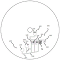
图1是根据本发明一个实施例的液体离散微流控芯片的示意图;1 is a schematic diagram of a liquid discrete microfluidic chip according to an embodiment of the present invention;
图2是根据本发明一个实施例的反应槽的示意图;2 is a schematic diagram of a reaction tank according to an embodiment of the present invention;
图3是根据本发明一个实施例的液体离散微流控芯片的立体图。3 is a perspective view of a liquid discrete microfluidic chip according to one embodiment of the present invention.
其中:反应槽100,微反应池阵列110,微反应池111,毛细通道120;液体泵送单元200,第二液体槽210,第一流道211,压缩室220,第二流道221,第三流道230;分配单元300,第一液体槽310,分配通道320,废液槽330,气孔400;基底层1;顶层2;中心孔3。Among them:
具体实施方式Detailed ways
下面将结合附图对本发明的技术方案进行清楚、完整地描述,显然,所描述的实施例是本发明一部分实施例,而不是全部的实施例。基于本发明中的实施例,本领域普通技术人员在没有做出创造性劳动前提下所获得的所有其他实施例,都属于本发明保护的范围。The technical solutions of the present invention will be clearly and completely described below with reference to the accompanying drawings. Obviously, the described embodiments are a part of the embodiments of the present invention, but not all of the embodiments. Based on the embodiments of the present invention, all other embodiments obtained by those of ordinary skill in the art without creative efforts shall fall within the protection scope of the present invention.
在本发明的描述中,需要说明的是,术语“中心”、“上”、“下”、“左”、“右”、“竖直”、“水平”、“内”、“外”等指示的方位或位置关系为基于附图所示的方位或位置关系,仅是为了便于描述本发明和简化描述,而不是指示或暗示所指的装置或元件必须具有特定的方位、以特定的方位构造和操作,因此不能理解为对本发明的限制。此外,术语“第一”、“第二”、“第三”仅用于描述目的,而不能理解为指示或暗示相对重要性。In the description of the present invention, it should be noted that the terms "center", "upper", "lower", "left", "right", "vertical", "horizontal", "inner", "outer", etc. The indicated orientation or positional relationship is based on the orientation or positional relationship shown in the accompanying drawings, which is only for the convenience of describing the present invention and simplifying the description, rather than indicating or implying that the indicated device or element must have a specific orientation or a specific orientation. construction and operation, and therefore should not be construed as limiting the invention. Furthermore, the terms "first", "second", and "third" are used for descriptive purposes only and should not be construed to indicate or imply relative importance.
在本发明的描述中,需要说明的是,除非另有明确的规定和限定,术语“安装”、“相连”、“连接”应做广义理解,例如,可以是固定连接,也可以是可拆卸连接,或一体地连接;可以是机械连接,也可以是电连接;可以是直接相连,也可以通过中间媒介间接相连,可以是两个元件内部的连通。对于本领域的普通技术人员而言,可以具体情况理解上述术语在本发明中的具体含义。In the description of the present invention, it should be noted that the terms "installed", "connected" and "connected" should be understood in a broad sense, unless otherwise expressly specified and limited, for example, it may be a fixed connection or a detachable connection Connection, or integral connection; can be mechanical connection, can also be electrical connection; can be directly connected, can also be indirectly connected through an intermediate medium, can be internal communication between two elements. For those of ordinary skill in the art, the specific meanings of the above terms in the present invention can be understood in specific situations.
本发明的近心端,是指在径向上更靠近旋转中心的一端。The proximal end of the present invention refers to the end closer to the center of rotation in the radial direction.
本发明的远心端,是指在径向上更远离旋转中心的一端。The distal end of the present invention refers to the end farther away from the center of rotation in the radial direction.
如图1所示,本发明提供的一种液体离散微流控芯片,包括:至少一个反应槽100,所述反应槽100内设置有微反应池阵列110,所述微反应池阵列110用于填充第一液体;至少一个液体泵送单元200,与所述反应槽100连接,用于将第二液体传送至所述反应槽100并覆盖所述第一液体;其中,所述第一液体与第二液体互不相容。As shown in FIG. 1 , a liquid discrete microfluidic chip provided by the present invention includes: at least one
参考图2,为图1中A部分的放大图,示出了反应槽100内的结构。其中,反应槽100内的微反应池阵列110是由多个微反应池111组成的阵列。微反应池阵列110中包含的微反应池111数量根据实际需要而设定。在一些微反应池阵列110中,微反应池111数量可以为几十个到几千万个。微反应池111等间距排布组成微反应池阵列110。由于微反应池111可以容纳第一液体,通过将第一液体填充满反应槽100内的微反应池阵列110,即可由微反应池111的数量得出离散化的第一液体的数量。Referring to FIG. 2 , it is an enlarged view of part A in FIG. 1 , showing the structure in the
同时,第一液体与第二液体互不相容。例如,第一液体是水溶液,第二液体是有机溶液;或者,第一液体是有机溶液,第二液体是水溶液。在使用过程中,先在微反应池111填充第一液体,再通入第二液体,对于后流进反应槽100内的第二液体,由于其与第一液体互不相容,因此在第二液体流入的流速较小时会将第一液体密封在各个微反应池111中,形成一个个以微反应池111为单元的独立微反应器,实现了液体的离散化。液体离散微流控芯片特别适合用于检测待测物浓度较低的样品,例如第一液体中含有待测物且待测物的含有量较低而不易被检测,通过该微流控芯片实现了第一液体的离散化,达到浓缩待测物的效果,由此可以快速、准确的检测出微反应池111的待测物,实现高灵敏度检测。At the same time, the first liquid and the second liquid are incompatible with each other. For example, the first liquid is an aqueous solution and the second liquid is an organic solution; alternatively, the first liquid is an organic solution and the second liquid is an aqueous solution. During use, the first liquid is filled in the
继续参考图1,所述微流控芯片还包括分配单元300,用于将第一液体分配至所述反应槽100;所述分配单元300设置有:第一液体槽310,用于装载第一液体;分配通道320,首端与所述第一液体槽310的出口连接,中段与所述反应槽100的近心端连接;废液槽330,与所述分配通道320的末端连接。由此,可以先在第一液体槽310内引入第一液体,再经由分配通道320将第一液体分配至不同的反应槽100中,而过量的第一液体则会流入废液槽330中,实现一次加样即可自动完成填充所有不同的反应槽100,可以减少工作过程中的人工操作,也避免了人工操作带来的误差。Continuing to refer to FIG. 1 , the microfluidic chip further includes a
为了增加该微流控芯片的实用性,第一液体槽310还设置有至少一个气孔400,用于注入第一液体以及排出气体。同样的,废液槽330还设置有至少一个气孔400,用于排出气体。气孔400的设置可以使得微流控芯片内的流道和腔体与大气连通,能确保内部流体流动更顺畅。In order to increase the practicability of the microfluidic chip, the
该微流控芯片可以通过离心力将第一液体由分配单元300引入各反应槽100中,以更高效的实现第一液体的分配。由此,微流控芯片具备旋转中心,所述第一液体槽310、分配通道320和反应槽100与所述旋转中心之间的径向距离依次增大。即,分配通道320位于第一液体槽310径向向外的一侧,反应槽100位于分配通道320径向向外的一侧。同样的,废液槽330与旋转中心之间的径向距离大于分配通道320与旋转中心之间的径向距离,废液槽330位于分配通道320径向向外的一侧。The microfluidic chip can introduce the first liquid from the
为了更好的为微流控芯片提供离心力,该微流控芯片具有中心孔3,并可通过中心孔3使得微流控芯片固定于离心电机上(图未示)。由此,微流控芯片可在离心电机的带动下进行离心运动,并在离心力的作用下,第一液体从第一液体槽310流出,经由分配通道320分配到不同的反应槽100内,而过量的液体则流入废液槽330。In order to better provide centrifugal force for the microfluidic chip, the microfluidic chip has a
继续参考图1,该微流控芯片还包括毛细通道120,所述毛细通道120的近心端与所述反应槽100的远心端连接,所述毛细通道120的远心端与所述液体泵送单元200连接;所述毛细通道120具有弯曲结构,所述毛细通道120与所述旋转中心之间的最短径向距离小于所述反应槽100的近心端与所述旋转中心之间的径向距离;所述毛细通道120的远心端与所述旋转中心之间的径向距离大于所述反应槽100的远心端与所述旋转中心之间的径向距离。因此在高速的离心转动下,第一液体并不会越过毛细通道120而从其远心端排出,而是在毛细通道120中具有与反应槽100液位高度相同的液柱。这样,可以使用毛细通道120对第一液体进行定量,使得相同的反应槽100在每次液体分配时都被分配到等量的第一液体,并使等量的第一液体填充于反应槽100的微反应池111内。Continuing to refer to FIG. 1 , the microfluidic chip further includes a
在第一液体填充反应槽100的微反应池111完成后,再通过液体泵送单元200将第二液体传送至所述反应槽100并覆盖所述第一液体。液体泵送单元200包括:第二液体槽210,用于装载第二液体;压缩室220,用于装载可压缩介质。其中,可压缩介质可以被压缩,也可以发生膨胀。由此,可以利用可压缩介质膨胀产生的驱动力将第二液体再传送至反应槽100中。该微流控芯片中,同样可通过离心运动实现可压缩介质的被压缩和膨胀,以驱动第二液体传送至反应槽100。为此,所述反应槽100、第二液体槽210和压缩室220与所述旋转中心之间的径向距离依次增大。After the first liquid fills the
进一步的,所述第二液体槽210的出口连接第一流道211,所述压缩室220的出口连接第二流道221,所述第一流道211和所述第二流道221相交后与第三流道230连接;所述反应槽100的远心端连接有毛细通道120,所述第三流道230通过所述毛细通道120与所述反应槽100连接。其中,所述第二流道221、第三流道230和毛细通道120的尺寸大于所述第一流道211的尺寸。由此,在离心力的作用下,第二液体从第二液体槽210向径向向外的方向流出,并流入压缩室220对位于其内的可压缩介质进行压缩。当第一液体填充微反应池111完毕后,操作微流控芯片的离心速度快速降低,此时,压缩室220内被压缩的可压缩介质会发生膨胀,从而对流入压缩室220的第二液体产生驱动力,起到将第二液体泵出的作用。同时,由于第二流道221、第三流道230和毛细通道120的尺寸大于第一流道211的尺寸,则第一流道211比第三流道230和毛细通道120具有更大的流体阻力,因此,由压缩室220泵出的第二液体会更少地回流到第二液体槽210,而是更多的通过毛细通道120泵送到反应槽100内。其中,所述流道的尺寸是指流体在流道中的流通面积,流道的尺寸越大则其流通面积越大,流体阻力越小,越有利于流道内的流体流动。本领域技术人员可以通过增加流道的宽度或者通过增加流道的深度以得到更大的流道尺寸,在此并不做特别限定。Further, the outlet of the
在此过程中,在第一液体填充微反应池111完毕后残余在毛细通道120中的以及反应槽100内未填充入微反应池111的第一液体,会被泵入反应槽100的第二液体排挤,逐渐经过分配通道320流进废液槽330内,直至该部分第一液体全部被排除出反应槽100,而第二液体流入反应槽100并覆盖整个微反应池阵列110。当然,如果泵入的第二液体量较大,过量的第二液体也会经过分配流道流入废液槽330内被收集。In this process, the first liquid remaining in the
由此,仅需向微流控芯片进行两步加液(分别加入第一液体和第二液体)的操作,即可实现对液体的离散化,不仅操作方法简单易行,对操作人员要求低,而且对设备要求也不高,相当易于实现集成化和自动化。Therefore, only two steps of adding liquid (adding the first liquid and the second liquid respectively) to the microfluidic chip can realize the discretization of the liquid, which is not only simple and easy to operate, but also has low requirements for operators. , and the equipment requirements are not high, and it is quite easy to realize integration and automation.
进一步的,可压缩介质为空气。Further, the compressible medium is air.
进一步的,毛细通道120的内表面经过改性处理,使得其对第一液体的虹吸作用减小而对第二液体的虹吸作用增大。例如,当第一液体是有机溶液、第二液体是水溶液时,毛细通道120经过亲水改性处理;当第一液体是水溶液、第二液体是有机溶液时,毛细通道120经过疏水改性处理,由此实现毛细通道120对第一液体的虹吸作用减小而对第二液体的虹吸作用增大。Further, the inner surface of the
其中,亲水改性是指使得毛细通道120的表面水接触角小于90°,具体的,可以通过表面活性剂、硅烷化试剂、纳米材料溶液等试剂和/或等离子体处理、紫外光辐射等方式实现毛细通道120的表面亲水改性处理;疏水改性是指使得毛细通道120的表面水接触角大于90°,具体的,可以通过氟试剂、硅烷化试剂、纳米材料溶液等试剂实现毛细通道120的表面疏水改性处理。Wherein, the hydrophilic modification refers to making the surface water contact angle of the
第二液体槽210设置有至少一个气孔400,用于注入第二液体以及排出气体。进一步的,在通过气孔400向第二液体槽210内注入第二液体完成后,密封第二液体槽210上的气孔400,由此,会由于第二液体槽210的空气阻力作用,使得压缩室220在泵送第二液体时,有更少的第二液体回流到第二液体槽210内。The
为了使得第一液体更容易填充到微反应池111内并使得第一液体能被保留在微反应池111中,微反应池111由外向内(由微反应池111入口向底部的方向)具有拔模倾斜角,优选的拔模角度为2°~10°。微反应池111的深宽比为0.4~2。In order to make it easier for the first liquid to be filled into the
微反应池111的形状可以是圆形、三角形、六边形等任意几何形状,微反应池111的体积容量可以是皮升至纳升,在此不做特别的限定。The shape of the
为提高微流控芯片集成度和方便使用,在微反应池111内可预埋有反应试剂,预埋的反应试剂为冻干试剂和/或凝胶试剂。进一步的,由于分配流道连接多个反应槽100,因此可以在不同的反应槽100内预埋相同的反应试剂,也可以在不同的反应槽100内预埋不同的反应试剂,而不同的反应试剂可以对应检测不同的指标,由此,即可以针对同一样本(第一液体)进行单指标或多指标的高灵敏度检测。In order to improve the integration degree of the microfluidic chip and facilitate the use, reaction reagents can be pre-embedded in the
进一步的,第一液体包括颗粒物质,例如颗粒物质为微纳米磁珠、细胞、外泌体等,且颗粒物质能够被填充入微反应池111中。Further, the first liquid includes particulate matter, for example, the particulate matter is micro-nano magnetic beads, cells, exosomes, etc., and the particulate matter can be filled into the
进一步的,第二液体为可凝固的相变材料,相变材料在室温下呈现固体状态,而在受热至其熔点温度时则发生相变成为液体状态。优选的,相变材料为石蜡。于是,在第一液体分配到反应槽100的过程中,相变材料被加热熔融成液态,并按照上述方式流向可压缩介质腔室。当快速降低离心转速时,相变材料受到可压缩介质的膨胀驱动力作用,再按照上述的方式填充至反应槽100,从而实现对微反应池111内第一液体进行密封。Further, the second liquid is a solidifiable phase change material, and the phase change material is in a solid state at room temperature, and changes into a liquid state when heated to its melting point temperature. Preferably, the phase change material is paraffin. Thus, in the process of distributing the first liquid into the
进一步的,以上的分配单元300、反应槽100、毛细通道120和液体泵送单元200组成一个离散单元,完成一组第一液体的离散化,在该微流控芯片中,可以根据需要,设置有多组离散单元,由此,可以在一个微流控芯片中实现多组第一液体的离散化。Further, the
参考图3所示,所述微流控芯片为双层结构,包括基底层1和顶层2,顶层2与基底层1相对盖合,其中,分配单元300、反应槽100和液体泵送单元200结构均设置在基底层1,分配单元300、反应槽100和液体泵送单元200结构为设置在基底层1的腔室;或者分配单元300、反应槽100和液体泵送单元200结构为设置在基底层1的凹槽结构,顶层2与基底层1密封形成分配单元300、反应槽100和液体泵送单元200结构;气孔400设置在顶层2,为贯穿盖板的通孔结构。Referring to FIG. 3 , the microfluidic chip has a double-layer structure, including a base layer 1 and a
进一步的,本发明还提供一种使用上述微流控芯片的方法,包括步骤:Further, the present invention also provides a method for using the above-mentioned microfluidic chip, comprising the steps of:
在第一液体槽加入第一液体,在第二液体槽加入第二液体;Add the first liquid to the first liquid tank, and add the second liquid to the second liquid tank;
进行微流控芯片的离心转动,使第一液体经由分配单元流入反应槽,并填充入微反应池内,同时第二液体流出第二液体槽进入压缩室并对可压缩介质进行压缩;Perform centrifugal rotation of the microfluidic chip, so that the first liquid flows into the reaction tank through the distribution unit, and fills the micro-reaction tank, while the second liquid flows out of the second liquid tank into the compression chamber and compresses the compressible medium;
快速降低离心转速,使第二液体被泵入反应槽内并覆盖第一液体。Quickly reduce the centrifugal speed so that the second liquid is pumped into the reaction tank and covers the first liquid.
进一步的,本发明还提供一种检测设备,包括上述的微流控芯片,还包括:温控装置,用于给反应槽100和/或冷却,提供必要的反应条件;光学装置,用于在反应过程中和/或反应结束后对微反应池111进行检测。该微流控芯片通过与其他辅助设备的结合,可以应用于不同的需要进行液体离散化的领域。Further, the present invention also provides a detection device, comprising the above-mentioned microfluidic chip, and further comprising: a temperature control device for providing necessary reaction conditions for the
实施例1Example 1
本实施例中,以应用于数字PCR领域为例,详细说明本发明的微流控芯片。微流控芯片为离心式微流控芯片,对称设置有四组离散单元(图示出其中一组),每一离散单元包括一个分配单元300、三个反应槽100、一个液体泵送单元200。分配单元300包括第一液体槽310,分配通道320和废液槽330。其中,分配通道320连接三个反应槽100,三个反应槽100各自通过毛细通道120与液体泵送单元200连接。反应槽100中具有由20000个微反应池111构成的微反应池阵列110。微反应池111的形状为圆形,拔模角度为6°,体积容量为0.1纳升,深宽比为0.8,微反应池111之间的孔间距为0.01mm。In this embodiment, the microfluidic chip of the present invention is described in detail by taking the application in the field of digital PCR as an example. The microfluidic chip is a centrifugal microfluidic chip, and four groups of discrete units (one group is shown in the figure) are symmetrically arranged, and each discrete unit includes a
液体泵送单元200包括:第二液体槽210和压缩室220,所述第二液体槽210的出口连接第一流道211,所述压缩室220的出口连接第二流道221,所述第一流道211和所述第二流道221相交后与第三流道230连接,第三流道230再通过毛细通道120与反应槽100连接。其中,第一液体为含有靶核酸序列的PCR反应试剂,第二液体为油相试剂,PCR反应试剂与油相试剂互不相容,压缩室220内的可压缩和膨胀的介质为空气。The
当把微流控芯片通过中心孔3固定在离心电机并启动旋转时,利用离心力可以将引入到第一液体槽310中的PCR反应试剂通过分配通道320分配到不同的反应槽100中,并且被填充到微反应池111中,而过量的PCR反应试剂流进废液槽330中。由于毛细通道120的峰高处距离旋转中心的距离(毛细通道120至旋转中心的最小距离)小于反应槽100的入口至旋转中心的距离,因此在高速的离心转动下,PCR反应试剂并不会越过毛细通道120的峰高而从毛细通道120远心端排出,而是在毛细通道120中具有与反应槽100液位高度相同的液柱。When the microfluidic chip is fixed to the centrifugal motor through the
与此同时,第二液体槽210内的油相试剂也会在离心力的作用下向径向向外的方向流出,从而从第一流道211流出,并经过第二流道221流向压缩室220,并对压缩室220内的空气进行压缩。当完成PCR反应试剂分配与填充后,快速降低离心转速,可以使得压缩室220内被压缩的空气发生膨胀而将压缩室220内的油相试剂泵出。由于第一流道211比第三流道230和毛细通道120尺寸小,具有更大的流体阻力,这会使得流体损耗更多的动能,因此压缩室220内泵出的油相试剂会更少地回流到第二液体槽210,而是更多的泵送到毛细通道120而进入反应槽100内。At the same time, the oil-phase reagent in the
由此,在油相试剂泵送的过程中,位于毛细通道120和反应槽100中没有填充进微反应池111的PCR反应试剂将会逐渐流进分配通道320,直至被完全排出毛细通道120和反应槽100,流入废液槽330。对于流进反应槽100的油相试剂,由于其与PCR反应试剂互不相容并且流速较小,因此覆盖会微反应池111,并将其中的PCR反应试剂密封,形成一个个以微反应池111为单位的微反应单元。由于靶核酸序列在PCR反应试剂中的浓度较低,因此通过此离散化过程可以使得每个微反应池111中至多含有1个靶核酸序列分子。对于过多的油相试剂,可在可压缩介质膨胀产生的驱动力作用下,继续充满反应槽100,而过量的油相试剂也会经分配通道320流入废液槽330中收集。Therefore, during the pumping process of the oil phase reagent, the PCR reaction reagent located in the
通过以上过程,即可得到离散化的PCR反应试剂,微反应池111中PCR反应试剂的在配套的温度控制装置的精准温度控制下,发生PCR反应。经过40次PCR温控循环后,微反应池111中的PCR反应试剂如果含有靶核酸序列,将产生足够强的荧光信号而被光学检测装置检测。最终,通过分析光学检测装置检测的荧光信号即可以得到靶核酸序列的浓度。Through the above process, a discrete PCR reaction reagent can be obtained, and the PCR reaction reagent in the
最后应说明的是:以上各实施例仅用以说明本发明的技术方案,而非对其限制;尽管参照前述各实施例对本发明进行了详细的说明,本领域的普通技术人员应当理解:其依然可以对前述各实施例所记载的技术方案进行修改,或者对其中部分或者全部技术特征进行等同替换;而这些修改或者替换,并不使相应技术方案的本质脱离本发明各实施例技术方案的范围。Finally, it should be noted that the above embodiments are only used to illustrate the technical solutions of the present invention, but not to limit them; although the present invention has been described in detail with reference to the foregoing embodiments, those of ordinary skill in the art should understand that: The technical solutions described in the foregoing embodiments can still be modified, or some or all of the technical features thereof can be equivalently replaced; and these modifications or replacements do not make the essence of the corresponding technical solutions deviate from the technical solutions of the embodiments of the present invention. scope.
Claims (10)
Priority Applications (1)
| Application Number | Priority Date | Filing Date | Title |
|---|---|---|---|
| CN202010458732.0A CN111604096B (en) | 2020-05-27 | 2020-05-27 | A liquid discrete microfluidic chip and method of using the same |
Applications Claiming Priority (1)
| Application Number | Priority Date | Filing Date | Title |
|---|---|---|---|
| CN202010458732.0A CN111604096B (en) | 2020-05-27 | 2020-05-27 | A liquid discrete microfluidic chip and method of using the same |
Publications (2)
| Publication Number | Publication Date |
|---|---|
| CN111604096A true CN111604096A (en) | 2020-09-01 |
| CN111604096B CN111604096B (en) | 2022-03-04 |
Family
ID=72196286
Family Applications (1)
| Application Number | Title | Priority Date | Filing Date |
|---|---|---|---|
| CN202010458732.0A Active CN111604096B (en) | 2020-05-27 | 2020-05-27 | A liquid discrete microfluidic chip and method of using the same |
Country Status (1)
| Country | Link |
|---|---|
| CN (1) | CN111604096B (en) |
Cited By (1)
| Publication number | Priority date | Publication date | Assignee | Title |
|---|---|---|---|---|
| CN116237102A (en) * | 2023-05-11 | 2023-06-09 | 杭州博日科技股份有限公司 | Microfluidic chip |
Citations (4)
| Publication number | Priority date | Publication date | Assignee | Title |
|---|---|---|---|---|
| US20180056288A1 (en) * | 2014-10-22 | 2018-03-01 | The Regents Of The University Of California | High Definition Microdroplet Printer |
| CN108479868A (en) * | 2018-03-07 | 2018-09-04 | 清华大学 | Siphon valve and its application process are interrupted for centrifugal type microfludic chip |
| CN209778828U (en) * | 2019-02-19 | 2019-12-13 | 深圳市刚竹医疗科技有限公司 | centrifugal micro-fluidic chip structure and nucleic acid analysis device |
| CN210522482U (en) * | 2019-05-17 | 2020-05-15 | 湖南乐准智芯生物科技有限公司 | Micro-reaction chamber array structure |
-
2020
- 2020-05-27 CN CN202010458732.0A patent/CN111604096B/en active Active
Patent Citations (4)
| Publication number | Priority date | Publication date | Assignee | Title |
|---|---|---|---|---|
| US20180056288A1 (en) * | 2014-10-22 | 2018-03-01 | The Regents Of The University Of California | High Definition Microdroplet Printer |
| CN108479868A (en) * | 2018-03-07 | 2018-09-04 | 清华大学 | Siphon valve and its application process are interrupted for centrifugal type microfludic chip |
| CN209778828U (en) * | 2019-02-19 | 2019-12-13 | 深圳市刚竹医疗科技有限公司 | centrifugal micro-fluidic chip structure and nucleic acid analysis device |
| CN210522482U (en) * | 2019-05-17 | 2020-05-15 | 湖南乐准智芯生物科技有限公司 | Micro-reaction chamber array structure |
Cited By (1)
| Publication number | Priority date | Publication date | Assignee | Title |
|---|---|---|---|---|
| CN116237102A (en) * | 2023-05-11 | 2023-06-09 | 杭州博日科技股份有限公司 | Microfluidic chip |
Also Published As
| Publication number | Publication date |
|---|---|
| CN111604096B (en) | 2022-03-04 |
Similar Documents
| Publication | Publication Date | Title |
|---|---|---|
| Wang et al. | Concentration gradient generation methods based on microfluidic systems | |
| CN101486004B (en) | Automatic device for quantitatively distributing microfluid and using method | |
| AU2001284700B2 (en) | Methods and devices for high throughput fluid delivery | |
| Wang et al. | Electroosmotic pumps and their applications in microfluidic systems | |
| US6669831B2 (en) | Microfluidic devices and methods to regulate hydrodynamic and electrical resistance utilizing bulk viscosity enhancers | |
| CN109453827B (en) | Microfluidic chip for flow control based on lyophilic and/or lyophobic microarrays | |
| US8652852B2 (en) | Method of pumping fluid through a microfluidic device | |
| CN207981204U (en) | Microlayer model generates system | |
| CN109395788B (en) | A chip device for preparing droplets in a tube | |
| AU2001284700A1 (en) | Methods and devices for high throughput fluid delivery | |
| JP2004500578A (en) | Method for reducing fluid carryover in microfluidic devices | |
| CN109746059B (en) | Micro-droplet generation system | |
| CN110437992A (en) | A kind of liquid phase sample is extensive, fast digitizing decomposition chip and its application method | |
| US20020144895A1 (en) | Methods and systems for enhanced fluid delivery of electrical currents to fluidic systems | |
| CN112076807A (en) | A microfluidic chip and device for spontaneously forming water-in-oil droplets | |
| CN114798025A (en) | Micro-droplet high-flux generating device | |
| CN111957361A (en) | Micro-droplet preparation system, micro-fluidic chip and design method thereof | |
| CN210510505U (en) | Siphon valve device, microfluidic structure and analysis device | |
| CN209287360U (en) | The micro-fluidic chip of flow control is realized based on the microarray of lyophily and/or lyophoby | |
| CA2624914A1 (en) | Microchip-based acoustic trapping or capture of cells for forensic analysis and related method thereof | |
| CN110369011A (en) | Micro liquid transfer device, control equipment and control method based on hydraulic-driven | |
| CN207614860U (en) | Microlayer model generating means | |
| CN115353949A (en) | Centrifugal multiple digital PCR micro-droplet generation chip | |
| CN113318796B (en) | Centrifugal droplet generation chip | |
| CN111604096A (en) | A liquid discrete microfluidic chip and method of using the same |
Legal Events
| Date | Code | Title | Description |
|---|---|---|---|
| PB01 | Publication | ||
| PB01 | Publication | ||
| SE01 | Entry into force of request for substantive examination | ||
| SE01 | Entry into force of request for substantive examination | ||
| GR01 | Patent grant | ||
| GR01 | Patent grant |