CN111593832A - Partition wall - Google Patents
Partition wall Download PDFInfo
- Publication number
- CN111593832A CN111593832A CN201910644225.3A CN201910644225A CN111593832A CN 111593832 A CN111593832 A CN 111593832A CN 201910644225 A CN201910644225 A CN 201910644225A CN 111593832 A CN111593832 A CN 111593832A
- Authority
- CN
- China
- Prior art keywords
- partition
- subunit
- rocker
- actuator
- groove
- Prior art date
- Legal status (The legal status is an assumption and is not a legal conclusion. Google has not performed a legal analysis and makes no representation as to the accuracy of the status listed.)
- Pending
Links
- 238000005192 partition Methods 0.000 title claims abstract description 133
- 238000003825 pressing Methods 0.000 claims description 15
- 229910052602 gypsum Inorganic materials 0.000 claims description 12
- 239000010440 gypsum Substances 0.000 claims description 12
- 230000005540 biological transmission Effects 0.000 claims description 8
- 239000011241 protective layer Substances 0.000 claims description 6
- 229920000742 Cotton Polymers 0.000 claims description 4
- 238000000465 moulding Methods 0.000 claims description 2
- 230000013011 mating Effects 0.000 claims 1
- 238000009413 insulation Methods 0.000 description 11
- 238000009434 installation Methods 0.000 description 6
- 238000005034 decoration Methods 0.000 description 4
- XAGFODPZIPBFFR-UHFFFAOYSA-N aluminium Chemical compound [Al] XAGFODPZIPBFFR-UHFFFAOYSA-N 0.000 description 2
- 229910052782 aluminium Inorganic materials 0.000 description 2
- 239000004568 cement Substances 0.000 description 2
- 238000005520 cutting process Methods 0.000 description 2
- 230000000694 effects Effects 0.000 description 2
- 239000000945 filler Substances 0.000 description 2
- 239000011521 glass Substances 0.000 description 2
- 239000003292 glue Substances 0.000 description 2
- 238000004519 manufacturing process Methods 0.000 description 2
- 238000000034 method Methods 0.000 description 2
- 238000004321 preservation Methods 0.000 description 2
- 210000002268 wool Anatomy 0.000 description 2
- 238000010521 absorption reaction Methods 0.000 description 1
- 230000009286 beneficial effect Effects 0.000 description 1
- 238000010276 construction Methods 0.000 description 1
- 230000007547 defect Effects 0.000 description 1
- 238000010586 diagram Methods 0.000 description 1
- 238000004880 explosion Methods 0.000 description 1
- 230000003116 impacting effect Effects 0.000 description 1
- 239000011490 mineral wool Substances 0.000 description 1
- 238000012986 modification Methods 0.000 description 1
- 230000004048 modification Effects 0.000 description 1
- 230000002265 prevention Effects 0.000 description 1
- 230000002035 prolonged effect Effects 0.000 description 1
- 238000010079 rubber tapping Methods 0.000 description 1
- 239000007787 solid Substances 0.000 description 1
- 230000002269 spontaneous effect Effects 0.000 description 1
- 239000013589 supplement Substances 0.000 description 1
- 239000002023 wood Substances 0.000 description 1
Images


Classifications
-
- E—FIXED CONSTRUCTIONS
- E04—BUILDING
- E04B—GENERAL BUILDING CONSTRUCTIONS; WALLS, e.g. PARTITIONS; ROOFS; FLOORS; CEILINGS; INSULATION OR OTHER PROTECTION OF BUILDINGS
- E04B2/00—Walls, e.g. partitions, for buildings; Wall construction with regard to insulation; Connections specially adapted to walls
- E04B2/74—Removable non-load-bearing partitions; Partitions with a free upper edge
- E04B2/82—Removable non-load-bearing partitions; Partitions with a free upper edge characterised by the manner in which edges are connected to the building; Means therefor; Special details of easily-removable partitions as far as related to the connection with other parts of the building
- E04B2/827—Partitions constituted of sliding panels
Landscapes
- Engineering & Computer Science (AREA)
- Architecture (AREA)
- Physics & Mathematics (AREA)
- Electromagnetism (AREA)
- Civil Engineering (AREA)
- Structural Engineering (AREA)
- Building Environments (AREA)
Abstract
The application provides a partition, which comprises at least two partition subunits which are adjacently arranged, wherein one end of the former partition subunit, which is contacted with the latter partition subunit, is provided with a connecting part, one end of the latter partition subunit, which is contacted with the former partition subunit, is provided with a matching part, the former partition subunit and the latter partition subunit are fixedly connected with the matching part through the connecting part, a fixing device is arranged in the partition subunit at the end part, and the fixing device is abutted and fixed with a track arranged on a roof; and a tail plate is sleeved at one end of the partition subunit close to the wall at the end part.
Description
Technical Field
The application relates to but is not limited to the field of house decoration, in particular to a partition.
Background
With the continuous development of times, the decoration style requirements are more diversified, and for decoration of a plurality of office buildings, meeting rooms or other places, the partition is a common treatment method in decoration design, can spatially separate rooms, achieves the purpose of multiple purposes of one room, and is easier to reconstruct than a solid wall.
However, the existing partition has the problems of heavy self, inconvenient push-pull, not tight sound insulation, poor aesthetic property and the like.
Disclosure of Invention
The application provides a partition, easy dismounting, sound insulation performance are good.
In order to achieve the purpose of the application, the technical scheme adopted by the application is as follows:
the application provides a partition, which comprises at least two partition subunits which are adjacently arranged, wherein one end of the former partition subunit, which is contacted with the latter partition subunit, is provided with a connecting part, one end of the latter partition subunit, which is contacted with the former partition subunit, is provided with a matching part, the former partition subunit and the latter partition subunit are fixedly connected with the matching part through the connecting part,
a fixing device is arranged in the partition subunit at the end part and is abutted and fixed with a track arranged on a roof;
and a tail plate is sleeved at one end of the partition subunit close to the wall at the end part.
Compared with the prior art, the method has the following beneficial effects:
the application provides a wall, through set up fixing device in the wall subelement of tip for locking or unclamping cut off the subelement, it is convenient to set up the inside fixing device control of tip wall subelement, make to cut off holistic push-and-pull more convenient, set up connecting portion and cooperation portion on the contact end of adjacent wall subelement simultaneously, make adjacent wall subelement contact inseparabler, improve and cut off holistic sound insulation performance. The tail plate is sleeved at one end, close to the wall, of the partition subunit at the end part, so that the plurality of partition subunits are convenient to install, the partition of the partition to the spaces on two sides is enhanced, and the sound insulation performance is further improved. In addition, the partition structure that this application provided is simple relatively, and operational reliability is high, and long service life has improved the practicality of this partition greatly.
Other features and advantages of the present application will be set forth in the description that follows.
Drawings
The accompanying drawings are included to provide a further understanding of the claimed subject matter and are incorporated in and constitute a part of this specification, illustrate embodiments of the subject matter and together with the description serve to explain the principles of the subject matter and not to limit the subject matter.
FIG. 1 is a schematic cross-sectional view (top view) of a partition according to an embodiment of the present application;
FIG. 2 is an enlarged view of the structure of portion A of FIG. 1;
FIG. 3 is another schematic cross-sectional view (front view) of a partition according to an embodiment of the present disclosure;
FIG. 4 is a schematic diagram of the engagement of the rocker (gear) and the upper actuator (rack) according to the embodiment of the present application;
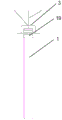
FIG. 5 is a schematic view of the overall installation of the partition according to an embodiment of the present application;
fig. 6 is a schematic view of a track layout of a partition according to an embodiment of the present application.
Illustration of the drawings:
1-partition subunit, 11-connecting part, 12-matching part, 13-fixing device, 131-four-bar telescoping mechanism, 132-upper driver, 133-lower driver, 134-rocker, 135-gear, 14-framework, 15-filling cotton, 16-gypsum board, 17-upper pressing strip, 18-lower pressing strip, 19-hanging wheel, 2-tail plate, 21-buffer strip, 3-track, 4-second track, 5-buffer, 6-soft rubber strip, 7-protective layer and 8-wall.
Detailed Description
To make the objects, technical solutions and advantages of the present application more apparent, embodiments of the present application will be described in detail below with reference to the accompanying drawings. It should be noted that the embodiments and features of the embodiments in the present application may be arbitrarily combined with each other without conflict.
The existing partition mainly comprises a wood partition, a cement wall partition and a glass partition, and the three partitions have great defects. The wooden partition is not damp-proof, waterproof and fireproof, is heavy as a whole, is inconvenient to push and pull and has poor sound insulation effect; the cement wall partition wall body is heavy, complex in construction and poor in attractiveness; the glass partition has poor reliability, and under the condition of high temperature, the situation of spontaneous explosion may occur.
The embodiment of the application provides a partition, as shown in fig. 1 and fig. 2, the partition comprises at least two partition sub-units 1 which are adjacently arranged, a connecting part 11 is arranged at one end of the previous partition sub-unit 1, which is contacted with the next partition sub-unit 1, a matching part 12 is arranged at one end of the next partition sub-unit 1, which is contacted with the previous partition sub-unit 1, and the previous partition sub-unit 1 and the next partition sub-unit 1 are contacted and connected with the matching part 12 through the connecting part 11; a fixing device 13 is arranged in the partition subunit 1 at the end part, and the fixing device 13 can be abutted and fixed with the track 3 arranged on the roof and/or the ground (the fixing device can be telescopic or can be lifted, and can be abutted and fixed when being extended or lifted); the end of the partition subunit 1 near the wall (the leftmost end or the rightmost end can be installed, and fig. 1 shows the situation that the end plates 2 are installed at both ends) is also sleeved with the end plate 2.
The partition provided by the application comprises at least two partition subunits 1 which are adjacently arranged, wherein the partition subunits 1 are 2 as shown in fig. 1, and one end of the previous partition subunit 1 is provided with a connecting part 11 which is matched with a matching part 12 arranged on the next partition subunit 1. The partition subunit 1 at the end (the leftmost side or the rightmost side, and the partition subunit 1 at the rightmost side in fig. 1 is shown to be provided with a fixing device) is provided with a fixing device 13 for fixing the position, the fixing device 13 is arranged inside the partition subunit 1, the partition subunit can be fixed to lock the position of the partition subunit when needed, when a plurality of partition subunits 1 are tightly contacted, the position of the partition subunit 1 at the end is fixed, so that the positions of all the partition subunits 1 can be fixed, and the partition can be normally used, it should be noted that, when being installed, the total length of the plurality of partition subunits 1 is smaller than the total width of the installation position (convenient to install), therefore, after the installation of the partition is completed, the tail plate 2 sleeved at one end of the partition subunit 1 at the end close to the wall can be pulled out to supplement the length of the plurality of partition subunits 1, the room is divided into two independent spaces. When the partition is not used, the fixing device 13 on the end partition subunit 1 is loosened, the end partition subunit 1 is detached (or moved to the wall side), and then all the partition subunits 1 are detached to be stored (or moved to the wall side), so that the space is saved. It should be noted that the fixing device 13 and the tail plate 2 may be only disposed on the partition subunit 1 at one end (that is, the number of the fixing device 13 and the tail plate 2 is 1), or may be disposed on the partition subunit 1 at the two ends (that is, the number of the fixing device 13 and the tail plate 2 is 2), and may be determined according to actual needs, which is not limited in this application.
The application provides a partition, through set up fixing device 13 in the partition subunit 1 at the tip, be used for locking or unclamp partition subunit 1, it is convenient to set up the inside fixing device 13 control at tip partition subunit 1, make and cut off the monolithic convenience, set up connecting portion 11 and cooperation portion 12 simultaneously on adjacent partition subunit 1's contact end, connecting portion 11 and cooperation portion 12 are fixed through fixing device behind the in close contact with, improve and cut off holistic sound insulation performance. One end of the partition subunit 1 at the end part close to the wall is sleeved with a stretchable tail plate 2, so that the plurality of partition subunits 1 are convenient to install, the partition of the partition to the spaces on two sides is enhanced, and the sound insulation performance is further improved. In addition, the partition structure that this application provided is simple relatively, and operational reliability is high, and long service life has improved the practicality of this partition greatly.
In an exemplary embodiment, as shown in fig. 3, the partition sub-unit 1 further includes a framework 14, filler wool 15, a gypsum board 16, an upper pressing strip 17 and a lower pressing strip 18, wherein the filler wool 15 is laid on the framework 14, the gypsum board 16 is fixed on both sides of the framework 14, the upper pressing strip 17 is disposed above the framework 14, and the lower pressing strip 18 is disposed below the framework 14. The connection of the four-bar mechanism to the upper and lower actuators is schematically indicated in fig. 3, but the connection of the rocker to the upper actuator is not shown.
Wherein, the framework 14 can be made of aluminum (for example, 50 aluminum square tube) to achieve the purpose of light weight and high strength; the filling cotton 15 is heat-preservation rock wool and has the functions of fire prevention, heat preservation and sound absorption; the gypsum board 16 may be selected from Luban universal boards, for example: the common gypsum board 16 with the thickness of 9.5mm, the waterproof gypsum board 16 with the thickness of 9.5mm or the fireproof waterproof gypsum board 16 with the thickness of 12 mm can be selected; the manner in which the gypsum board 16 is secured to the frame 14 can be varied, for example: fix through the four corners connection sign indicating number, perhaps fix gypsum board 16 on skeleton 14 through self-tapping screw, perhaps mode such as sticky selects for use by oneself as required can.
In an exemplary embodiment, as shown in fig. 3 and 4, the fixing device 13 includes an upper actuator 132, a gear 135 and a rocker 134, the upper actuator is disposed in the passage in the vertical direction of the partition subunit, a rack is disposed on the upper actuator, one end of the rocker is connected with the gear 135, one end of the rocker connected with the gear 135 is inserted into the partition subunit to be matched with the rack of the upper actuator, and the rotation of the rocker drives the upper actuator to extend or retract.
A channel for accommodating the upper transmission is arranged in the partition subunit at the end part, fig. 4 is a partial enlarged view of a circle marked in fig. 3, only the gear 135 and the upper transmission 132 are shown, other parts are omitted, the gear 135 can be directly or indirectly fixed on the framework 14, a limiting structure such as a through hole can be arranged in the channel, and the upper transmission 132 is limited to move only in the up-and-down direction. As shown, the upper actuator 132 is provided with a rack, and one end of the rocker is provided with a gear 135, for example, the rocker can be connected to a central shaft of the gear 135 in fig. 4, and the gear 135 can be driven to rotate by rotating the rocker. One end provided with a gear 135 is in transmission cooperation with a rack of the upper actuator 132, so that the rotation of the rocker 134 is converted into the up-and-down linear motion of the upper actuator 132, i.e., the rotation of the rocker 134 drives the upper actuator 132 to extend (or retract) to be fixed at the set position on the rail.
The four-bar mechanism 131 may be a telescopic mechanism formed by more links, for example, a five-bar mechanism is formed by adding an upper link in the middle of the upper end of the four-bar mechanism, and the upper link is connected to the upper actuator 132, so as to achieve the above-mentioned functions. It is easy to understand that the lower end, the left end and the right end of the four-bar mechanism can be added with connecting rods. As long as the link mechanism includes upper and lower ends that can be extended and retracted in the vertical direction, and left and right ends that can be extended and retracted in the horizontal direction.
In an exemplary embodiment, as shown in fig. 3, the fixing device 13 further includes a four-bar mechanism 131 and a lower driver 133, an upper end of the four-bar mechanism 131 is connected to the upper driver 132, a lower end of the four-bar mechanism 131 is connected to the lower driver 133, and the rocker 134 rotates to drive the lower driver 133 to extend or retract.
The lower end of the upper actuator 132 is connected to the upper end of the four-bar linkage 131, and the lower end of the four-bar linkage 131 is connected to the upper end of the lower actuator 133. The rotation of the rocker 134 drives the upper driver 132 to extend (or retract), the upper driver 132 drives the four-bar telescoping mechanism 131 to extend, and the four-bar telescoping mechanism 131 drives the lower driver 133 to extend, i.e., the rotation of the rocker 134 can simultaneously drive the upper driver 132 and the lower driver 133 to extend (or retract). It should be noted that in a different case, the upper and lower actuators 132 and 133 may be provided with only one for position locking. The position of the center point of the four-bar telescoping mechanism 131 is unchanged, that is, of the four vertexes of the four-bar telescoping mechanism 131, the left and right vertexes may be disposed in the horizontal slide so as to be movable only in the horizontal direction, and the upper and lower vertexes may be disposed in the vertical slide so as to be movable only in the vertical direction. The runners may be secured directly or indirectly to the frame 14.
In an exemplary embodiment, as shown in fig. 2, the connecting portion 11 is a semicircular protrusion, the matching portion 12 is a groove, and a cushion pad 5 is further disposed between the semicircular protrusion and the groove; or the connecting part 11 is a groove, the matching part 12 is a semicircular bulge, and a cushion pad 5 is arranged between the semicircular bulge and the groove.
The bulges and the grooves can be in an integrated structure with the partition subunit 1, so that the integral structural strength is improved; or the partition subunit 1 can be subsequently additionally installed after the production is finished, so that the mass production and the assembly are convenient. The cushion 5 can avoid the damage caused by the direct hard contact of the protrusion and the groove, and simultaneously, the cushion 5 can also enhance the sound insulation effect.
In an exemplary embodiment, as shown in fig. 2, a soft glue strip 6 is further disposed in the groove, and the soft glue strip 6 is configured to contact the protrusion.
One end of the soft rubber strip 6 is fixed, and the other end of the soft rubber strip is tightly attached to the bulge matched with the groove, so that the sound insulation performance of the partition can be further improved.
In an exemplary embodiment, the upper molding 17 is provided with a through hole (not shown), and the upper end of the upper actuator 132 can protrude from the through hole and abut against the rail 3.
The rocker 134 controls the upper actuator 132 to move, and the upper end of the upper actuator 132 extends out of the through hole of the upper pressing bar 17 to abut against a positioning structure (such as a positioning groove, a positioning block and the like) on the rail 3, so as to lock the end partition subunit 1. It should be noted that a through hole may be provided on the lower pressing bar 18, and when the lower actuator 133 is actuated, the lower end of the lower actuator 133 extends out of the through hole of the lower pressing bar 18 to abut against the ground, thereby assisting the locking end to block the sub-unit 1.
In an exemplary embodiment, as shown in fig. 3, the upper end of the upper pressing bar 17 is further provided with a hanging wheel 19, and the partition sub-unit 1 is mounted on the rail 3 through the hanging wheel 19, and the rail is clamped at a portion with a smaller diameter in the middle of the hanging wheel, so that the hanging wheel is prevented from falling off the rail.
In an exemplary embodiment, as shown in fig. 1, the side of the tail plate 2 close to the wall is further provided with a buffer strip 21.
The buffer strip 21 can avoid the tailboard 2 from directly impacting the wall 8, effectively reduce vibration and buffer, and avoid damage.
In an exemplary embodiment, as shown in fig. 3, the skeleton 14 is further surrounded by a protective layer 7.
The protective layer 7 is arranged to protect the periphery of the framework 14 by edge wrapping, so that the service life of the partition subunit 1 can be greatly prolonged. It should be noted that after the frame 14 is covered with the protective layer 7 (the protective layer is only provided around the frame to be covered with a tape and does not cover the main body of the gypsum board), the frame 14 is provided with the upper and lower pressing strips 17 and 18.
In addition, besides the rail 3 at the installation position (as shown in fig. 4), a second rail 4 for transporting and storing the partition sub-unit 1 is further arranged, one end of the second rail 4 is connected with the original installation rail 3, and the partition can be stacked on a wall 8 through the second rail 4 when not in use (as shown in fig. 5), so that the space is saved, and the next installation and use are facilitated.
At the bottom of the lower pressing strip 18 of the partition subunit 1, a roller can be arranged as required to further reduce friction force and facilitate the push-pull of the partition subunit 1.
The application provides a wall, through set up fixing device in the wall subelement of tip for locking or unclamping cut off the subelement, it is convenient to set up the inside fixing device control of tip wall subelement, make to cut off holistic push-and-pull more convenient, set up connecting portion and cooperation portion on the contact end of adjacent wall subelement simultaneously, make adjacent wall subelement contact inseparabler, improve and cut off holistic sound insulation performance. The tail plate is sleeved at one end, close to the wall, of the partition subunit at the end part, so that the plurality of partition subunits are convenient to install, the partition of the partition to the spaces on two sides is enhanced, and the sound insulation performance is further improved. And set up the second track, accessible second track stacks a plurality of wall subelements in wall department when cutting off not using, saves space, is convenient for install once more and uses, has improved the practicality of cutting off greatly.
In the description of the present application, it should be noted that the terms "plurality" refer to two or more, and the directions or positional relationships indicated by the terms "upper", "lower", "one side", "the other side", "one end", "the other end", "left", "right", and the like are based on the directions or positional relationships shown in the drawings, and are only for convenience of describing the present application and simplifying the description, but do not indicate or imply that the structures referred to have a specific direction, are configured and operated in a specific direction, and thus cannot be construed as limiting the present application.
In the description of the embodiments of the present application, unless expressly stated or limited otherwise, the terms "connected," "connected," and "mounted" are to be construed broadly, e.g., the term "connected" may be a fixed connection, a removable connection, or an integral connection; they may be connected directly or indirectly through intervening media, or they may be interconnected between two elements. The specific meaning of the above terms in the present application can be understood in a specific case by those of ordinary skill in the art.
The embodiments described herein are exemplary rather than limiting and it will be apparent to those of ordinary skill in the art that many more embodiments and implementations are possible within the scope of the embodiments described herein. Although many possible combinations of features are shown in the drawings and discussed in the detailed description, many other combinations of the disclosed features are possible. Any feature or element of any embodiment may be used in combination with or instead of any other feature or element in any other embodiment, unless expressly limited otherwise.
The present application includes and contemplates combinations of features and elements known to those of ordinary skill in the art. The embodiments, features and elements that have been disclosed in this application may also be combined with any conventional features or elements to form unique aspects as defined by the claims. Any feature or element of any embodiment may also be combined with features or elements from other aspects to form another unique aspect as defined by the claims. Thus, it should be understood that any of the features shown and/or discussed in this application may be implemented alone or in any suitable combination. Accordingly, the embodiments are not limited except as by the appended claims and their equivalents. Furthermore, various modifications and changes may be made within the scope of the appended claims.
Claims (11)
1. A partition is characterized by comprising at least two partition subunits which are adjacently arranged, wherein one end of the front partition subunit, which is contacted with the rear partition subunit, is provided with a connecting part, one end of the rear partition subunit, which is contacted with the front partition subunit, is provided with a matching part, the front partition subunit and the rear partition subunit are in contact connection with the matching part through the connecting part,
and a fixing device is arranged in the partition subunit at the end part and can be abutted and fixed with a track arranged on a roof.
2. The partition of claim 1 wherein the partition sub-units further comprise a frame, infill cotton, gypsum board, upper and lower battens,
the filling cotton is laid on the framework, the gypsum board is fixed on two sides of the framework, the upper pressing strip is arranged above the framework, and the lower pressing strip is arranged below the framework.
3. Partition according to claim 2, characterised in that the fixing means comprise an upper actuator and a rocker,
the upper transmission device is arranged in a channel in the vertical direction of the partition subunit, a rack is arranged on the upper transmission device, one end of the rocker is connected with a gear, one end of the rocker, which is connected with the gear, is inserted into the partition subunit and is matched with the rack of the upper transmission device, and the rocker rotates to drive the upper transmission device to extend or retract.
4. The partition of claim 3, wherein the fixing device further comprises a link mechanism and a lower actuator, the link mechanism comprises an upper end and a lower end which can extend and retract in a vertical direction, and a left end and a right end which can extend and retract in a horizontal direction, the upper end of the link mechanism is connected with the upper actuator, the lower end of the link mechanism is connected with the lower actuator, and the rocker rotates to drive the lower actuator to extend or retract.
5. The partition of claim 1, wherein the connecting portion is a semicircular protrusion, the mating portion is a groove, and a cushion is disposed between the semicircular protrusion and the groove;
or the connecting part is a groove, the matching part is a semicircular bulge, and a cushion pad is arranged between the semicircular bulge and the groove.
6. Partition according to claim 5, wherein a soft rubber strip is further arranged in the groove, the soft rubber strip being arranged for contact with the protrusion.
7. The partition of claim 3, wherein the upper molding has a through hole, and an upper end of the upper actuator is capable of protruding from the through hole and abutting against the rail.
8. The partition of claim 2, wherein the upper end of the upper pressing bar is further provided with a hanging wheel, and the partition sub-unit is mounted on the rail through the hanging wheel.
9. The partition of claim 2, wherein the frame is further coated with a protective layer.
10. The partition according to any one of claims 1 to 9, wherein a tail plate is further sleeved at one end of the partition subunit at the end close to the wall.
11. The partition of claim 10, wherein a buffer strip is further arranged on one side of the tail plate close to the wall.
Priority Applications (1)
| Application Number | Priority Date | Filing Date | Title |
|---|---|---|---|
| CN201910644225.3A CN111593832A (en) | 2019-07-17 | 2019-07-17 | Partition wall |
Applications Claiming Priority (1)
| Application Number | Priority Date | Filing Date | Title |
|---|---|---|---|
| CN201910644225.3A CN111593832A (en) | 2019-07-17 | 2019-07-17 | Partition wall |
Publications (1)
| Publication Number | Publication Date |
|---|---|
| CN111593832A true CN111593832A (en) | 2020-08-28 |
Family
ID=72190796
Family Applications (1)
| Application Number | Title | Priority Date | Filing Date |
|---|---|---|---|
| CN201910644225.3A Pending CN111593832A (en) | 2019-07-17 | 2019-07-17 | Partition wall |
Country Status (1)
| Country | Link |
|---|---|
| CN (1) | CN111593832A (en) |
Cited By (1)
| Publication number | Priority date | Publication date | Assignee | Title |
|---|---|---|---|---|
| CN115977281A (en) * | 2023-02-19 | 2023-04-18 | 湖南及极科技有限公司 | Folding flexible partition wall |
Citations (6)
| Publication number | Priority date | Publication date | Assignee | Title |
|---|---|---|---|---|
| US4454690A (en) * | 1976-09-28 | 1984-06-19 | Panelfold, Inc. | Portable and operable wall system |
| JPH11182156A (en) * | 1997-12-18 | 1999-07-06 | Itoki Crebio Corp | Meeting device for suspended moving panels |
| CN201109952Y (en) * | 2007-08-14 | 2008-09-03 | 罗星阳 | Sound-proof mobile wall |
| CN202170581U (en) * | 2011-07-20 | 2012-03-21 | 杨维华 | Mobile partition |
| CN202595946U (en) * | 2012-04-20 | 2012-12-12 | 上海安得顺诺建筑装饰制品有限公司 | Moveable partition laminating type continuous rocking top bottom telescopic mechanism device |
| CN209114659U (en) * | 2018-11-20 | 2019-07-16 | 中建材创新科技研究院有限公司 | A kind of moveable partition |
-
2019
- 2019-07-17 CN CN201910644225.3A patent/CN111593832A/en active Pending
Patent Citations (6)
| Publication number | Priority date | Publication date | Assignee | Title |
|---|---|---|---|---|
| US4454690A (en) * | 1976-09-28 | 1984-06-19 | Panelfold, Inc. | Portable and operable wall system |
| JPH11182156A (en) * | 1997-12-18 | 1999-07-06 | Itoki Crebio Corp | Meeting device for suspended moving panels |
| CN201109952Y (en) * | 2007-08-14 | 2008-09-03 | 罗星阳 | Sound-proof mobile wall |
| CN202170581U (en) * | 2011-07-20 | 2012-03-21 | 杨维华 | Mobile partition |
| CN202595946U (en) * | 2012-04-20 | 2012-12-12 | 上海安得顺诺建筑装饰制品有限公司 | Moveable partition laminating type continuous rocking top bottom telescopic mechanism device |
| CN209114659U (en) * | 2018-11-20 | 2019-07-16 | 中建材创新科技研究院有限公司 | A kind of moveable partition |
Cited By (2)
| Publication number | Priority date | Publication date | Assignee | Title |
|---|---|---|---|---|
| CN115977281A (en) * | 2023-02-19 | 2023-04-18 | 湖南及极科技有限公司 | Folding flexible partition wall |
| CN115977281B (en) * | 2023-02-19 | 2024-01-19 | 湖南及极科技有限公司 | Folding telescopic partition wall |
Similar Documents
| Publication | Publication Date | Title |
|---|---|---|
| CN111593832A (en) | Partition wall | |
| CN210947392U (en) | Wallboard for assembly type building | |
| KR101265743B1 (en) | A combine device for prevent insulating and dewdrop of glass | |
| CN112252535B (en) | Indoor glass partition structure | |
| CN210713498U (en) | Green type building wallboard | |
| PT104012B (en) | MIXED WOOD-GLASS STRUCTURAL PANEL AND ITS PRODUCTION PROCESS | |
| CN218838879U (en) | Multilayer heat preservation decorative board | |
| CN216766900U (en) | Box house with noise reduction and heat insulation functions | |
| CN216740268U (en) | Novel transparent breathing type folded glass curtain wall | |
| CN215595084U (en) | A square cabin building base with a lifting structure | |
| CN207405839U (en) | A kind of glass curtain wall | |
| CN103912184A (en) | Full-hidden type aluminum-wood composite window and door | |
| CN223256726U (en) | Fire-resistant passive window | |
| CN120100301B (en) | Building curtain wall structure capable of being rotationally attached | |
| CN208235758U (en) | A kind of assembled movable partition | |
| CN216428773U (en) | Partition panel | |
| CN218911848U (en) | Assembled building sound insulation wall | |
| CN208164416U (en) | A kind of aluminum honeycomb panel | |
| CN217300296U (en) | Compound aluminum alloy French window | |
| CN218233805U (en) | Combined splicing type sound insulation room | |
| CN203783383U (en) | Aluminium-wood composite hidden sash | |
| CN110656728A (en) | Double-deck assembled side fascia | |
| CN218466853U (en) | High-efficient assembled house wallboard | |
| CN214616083U (en) | Bridge cut-off heat insulation aluminum alloy window capable of reducing noise | |
| CN217021807U (en) | A honeycomb composite board for car as a house |
Legal Events
| Date | Code | Title | Description |
|---|---|---|---|
| PB01 | Publication | ||
| PB01 | Publication | ||
| SE01 | Entry into force of request for substantive examination | ||
| SE01 | Entry into force of request for substantive examination | ||
| RJ01 | Rejection of invention patent application after publication | ||
| RJ01 | Rejection of invention patent application after publication |
Application publication date: 20200828 |