CN111567160A - A wheel track processing mechanism for tillage and sowing machinery - Google Patents
A wheel track processing mechanism for tillage and sowing machinery Download PDFInfo
- Publication number
- CN111567160A CN111567160A CN202010512425.6A CN202010512425A CN111567160A CN 111567160 A CN111567160 A CN 111567160A CN 202010512425 A CN202010512425 A CN 202010512425A CN 111567160 A CN111567160 A CN 111567160A
- Authority
- CN
- China
- Prior art keywords
- auger
- support
- shaft
- bracket
- rut
- Prior art date
- Legal status (The legal status is an assumption and is not a legal conclusion. Google has not performed a legal analysis and makes no representation as to the accuracy of the status listed.)
- Granted
Links
Images


Classifications
-
- A—HUMAN NECESSITIES
- A01—AGRICULTURE; FORESTRY; ANIMAL HUSBANDRY; HUNTING; TRAPPING; FISHING
- A01B—SOIL WORKING IN AGRICULTURE OR FORESTRY; PARTS, DETAILS, OR ACCESSORIES OF AGRICULTURAL MACHINES OR IMPLEMENTS, IN GENERAL
- A01B37/00—Devices for loosening soil compacted by wheels or the like
-
- A—HUMAN NECESSITIES
- A01—AGRICULTURE; FORESTRY; ANIMAL HUSBANDRY; HUNTING; TRAPPING; FISHING
- A01B—SOIL WORKING IN AGRICULTURE OR FORESTRY; PARTS, DETAILS, OR ACCESSORIES OF AGRICULTURAL MACHINES OR IMPLEMENTS, IN GENERAL
- A01B33/00—Tilling implements with rotary driven tools, e.g. in combination with fertiliser distributors or seeders, with grubbing chains, with sloping axles, with driven discs
- A01B33/02—Tilling implements with rotary driven tools, e.g. in combination with fertiliser distributors or seeders, with grubbing chains, with sloping axles, with driven discs with tools on horizontal shaft transverse to direction of travel
- A01B33/021—Tilling implements with rotary driven tools, e.g. in combination with fertiliser distributors or seeders, with grubbing chains, with sloping axles, with driven discs with tools on horizontal shaft transverse to direction of travel with rigid tools
- A01B33/022—Tilling implements with rotary driven tools, e.g. in combination with fertiliser distributors or seeders, with grubbing chains, with sloping axles, with driven discs with tools on horizontal shaft transverse to direction of travel with rigid tools with helicoidal tools
-
- A—HUMAN NECESSITIES
- A01—AGRICULTURE; FORESTRY; ANIMAL HUSBANDRY; HUNTING; TRAPPING; FISHING
- A01B—SOIL WORKING IN AGRICULTURE OR FORESTRY; PARTS, DETAILS, OR ACCESSORIES OF AGRICULTURAL MACHINES OR IMPLEMENTS, IN GENERAL
- A01B33/00—Tilling implements with rotary driven tools, e.g. in combination with fertiliser distributors or seeders, with grubbing chains, with sloping axles, with driven discs
- A01B33/08—Tools; Details, e.g. adaptations of transmissions or gearings
- A01B33/087—Lifting devices; Depth regulation devices; Mountings
Landscapes
- Life Sciences & Earth Sciences (AREA)
- Engineering & Computer Science (AREA)
- Mechanical Engineering (AREA)
- Soil Sciences (AREA)
- Environmental Sciences (AREA)
- Soil Working Implements (AREA)
Abstract
本发明公开了一种耕播机械用轮辙处理机构,其包括主支架、搅龙支架、搅龙轴、搅龙组件以及动力单元;所述搅龙支架转动安装在所述主支架的前端,且其相对于所述主支架的俯仰角度可由调节机构调节;所述搅龙轴转动安装在所述搅龙支架上,且其转动由所述动力单元驱动;所述搅龙组件安装在所述搅龙轴上。本发明的耕播机械用轮辙处理机构通过设置可调节搅龙支架相对于主支架俯仰角度的调节机构,使得搅龙组件上螺旋部的入土深度可调节,从而可根据不同松软程度的土壤调节螺旋部的入土深度以满足处理轮辙对浮土体积的需求,保证轮辙处理质量。
The invention discloses a wheel track processing mechanism for a tillage and seeding machine, which comprises a main support, an auger support, an auger shaft, an auger assembly and a power unit; the auger support is rotatably installed at the front end of the main support, And its pitch angle relative to the main support can be adjusted by an adjustment mechanism; the auger shaft is rotatably installed on the auger support, and its rotation is driven by the power unit; the auger assembly is installed on the on the auger shaft. The wheel rut treatment mechanism for tillage and seeding machinery of the present invention is provided with an adjustment mechanism that can adjust the pitch angle of the auger support relative to the main support, so that the depth of soil penetration of the screw part on the auger assembly can be adjusted, so that it can be adjusted according to soils with different degrees of softness. The depth of soil penetration of the helical part can meet the requirements for the volume of regolith for the treatment of wheel ruts and ensure the quality of wheel rut treatment.
Description
技术领域technical field
本发明涉及农业机械技术领域,特别是涉及一种耕播机械用轮辙处理机构。The invention relates to the technical field of agricultural machinery, in particular to a wheel track processing mechanism for tillage and sowing machinery.
背景技术Background technique
农业耕播机械是现代化农业的基础,其可执行自动化播种、施肥等作业,大大提升耕播效率。由于播种、施肥过程中需要对土地进行开种槽、开肥槽以让种子或肥料播撒至种槽、肥料槽中,使得种子得以种入土中以及肥料不易流失,为了进行开种槽、开肥槽,平土是农业耕播机械执行播种或施肥作业过程中不可或缺的一个步骤,平土主要目的是将高低不平的表面进行处理使其平整,如此才能开出连续的种槽或肥槽以方便播种、施肥。Agricultural tillage and sowing machinery is the foundation of modern agriculture. It can perform automated seeding, fertilization and other operations, greatly improving the efficiency of tillage and sowing. In the process of sowing and fertilization, it is necessary to open seed grooves and fertilizer grooves on the land so that seeds or fertilizers can be sown into the seed grooves and fertilizer grooves, so that the seeds can be planted in the soil and the fertilizers are not easily lost. Slots and soil leveling are an indispensable step in the process of seeding or fertilizing operations performed by agricultural tillage and sowing machines. The main purpose of soil leveling is to treat the uneven surface to make it level, so that continuous seed troughs or fertilizer troughs can be opened. To facilitate sowing and fertilizing.
现有农业耕播机械一般都是由拖拉机等牵引机械牵引执行作业,而拖拉机在前进过程中会产生较深的轮辙,这些轮辙不利于播种施肥作业,因此,拖拉机牵引农业耕播机械执行作业时,农业耕播机械需要将轮辙及时处理以保证后续的开槽、播种施肥作业的质量。现有农业耕播机械中,平土机构不能使用不同松软程度的土壤,对轮辙的处理质量不稳定。Existing agricultural tillage and seeding machinery is generally carried out by traction machinery such as tractors, and the tractor will produce deep ruts during the forward process, which are not conducive to seeding and fertilizing operations. During the operation, the agricultural tillage and seeding machinery needs to deal with the ruts in time to ensure the quality of the subsequent grooving, sowing and fertilization operations. In the existing agricultural tillage and sowing machines, the soil leveling mechanism cannot use soils with different degrees of softness, and the treatment quality of wheel ruts is unstable.
发明内容SUMMARY OF THE INVENTION
发明目的:为了克服现有技术中存在的不足,本发明提供一种可适应不同土壤,保证处理质量的耕播机械用轮辙处理机构。Purpose of the invention: In order to overcome the deficiencies in the prior art, the present invention provides a wheel track treatment mechanism for tillage and sowing machinery that can adapt to different soils and ensure treatment quality.
技术方案:为实现上述目的,本发明的耕播机械用轮辙处理机构,其包括主支架、搅龙支架、搅龙轴、搅龙组件以及动力单元;所述搅龙支架转动安装在所述主支架的前端,且其相对于所述主支架的俯仰角度可由调节机构调节;所述搅龙轴转动安装在所述搅龙支架上,且其转动由所述动力单元驱动;所述搅龙组件安装在所述搅龙轴上。Technical scheme: In order to achieve the above purpose, the wheel track processing mechanism for tillage and sowing machinery of the present invention includes a main support, an auger support, an auger shaft, an auger assembly and a power unit; the auger support is rotatably installed on the The front end of the main bracket, and its pitch angle relative to the main bracket can be adjusted by an adjustment mechanism; the auger shaft is rotatably mounted on the auger bracket, and its rotation is driven by the power unit; the auger shaft The assembly is mounted on the auger shaft.
进一步地,所述调节机构包括手柄座、调节手柄以及螺套转节;所述手柄座转动安装在所述主支架上,所述调节手柄转动安装在所述手柄座上,且所述调节手柄具有螺杆部;所述螺套转节转动安装在所述搅龙支架上;所述螺杆部与所述螺套转节呈螺纹副配合。Further, the adjustment mechanism includes a handle seat, an adjustment handle and a screw sleeve swivel; the handle seat is rotatably mounted on the main bracket, the adjustment handle is rotatably mounted on the handle seat, and the adjustment handle A screw part is provided; the screw sleeve rotating joint is rotatably mounted on the auger support; the screw part and the screw sleeve rotating joint are matched in a thread pair.
进一步地,所述搅龙轴上对称安装有两组所述搅龙组件,且每组所述搅龙组件均可相对于所述搅龙轴调节轴向位置。Further, two sets of the auger assemblies are symmetrically installed on the auger shaft, and each group of the auger assemblies can adjust the axial position relative to the auger shaft.
进一步地,所述搅龙组件包含两个对称设置的螺旋部,且两个所述螺旋部的螺旋方向相反。Further, the auger assembly includes two symmetrically arranged spiral parts, and the spiral directions of the two spiral parts are opposite.
进一步地,所述搅龙轴对应于每个所述搅龙组件均设有方轴段,所述搅龙组件包括中管部,所述中管部套设在所述方轴段上,且所述中管部上安装有用于顶紧所述方轴段外壁的顶紧螺钉。Further, the auger shaft is provided with a square shaft section corresponding to each of the auger assemblies, and the auger assembly includes a middle tube portion, and the middle tube portion is sleeved on the square shaft section, and A tightening screw for tightening the outer wall of the square shaft section is installed on the middle pipe portion.
进一步地,所述中管部包括圆管部,所述圆管部的两端各固定有中心具有方孔的端板;所述端板中部的方孔与所述方轴段滑动配合。Further, the middle tube portion includes a round tube portion, and both ends of the round tube portion are each fixed with an end plate with a square hole in the center; the square hole in the middle portion of the end plate is slidably fitted with the square shaft section.
进一步地,所述动力单元包括液压马达,所述液压马达通过油管连接比例阀,所述比例阀通过油管连接压力油源。Further, the power unit includes a hydraulic motor, the hydraulic motor is connected to a proportional valve through an oil pipe, and the proportional valve is connected to a pressure oil source through an oil pipe.
进一步地,还包括牵引支架,所述主支架通过浮动结构连接所述牵引支架。Further, a traction bracket is also included, and the main bracket is connected to the traction bracket through a floating structure.
有益效果:本发明的耕播机械用轮辙处理机构通过设置可调节搅龙支架相对于主支架俯仰角度的调节机构,使得搅龙组件上螺旋部的入土深度可调节,从而可根据不同松软程度的土壤调节螺旋部的入土深度以满足处理轮辙对浮土体积的需求,保证轮辙处理质量。Beneficial effects: The wheel track processing mechanism for the tillage and sowing machine of the present invention is provided with an adjustment mechanism that can adjust the pitch angle of the auger support relative to the main support, so that the depth of soil penetration of the screw part on the auger assembly can be adjusted, so that it can be adjusted according to different degrees of softness. The soil depth of the screw is adjusted to meet the needs of the regolith volume for the treatment of the wheel rut, and to ensure the quality of the wheel rut treatment.
附图说明Description of drawings
附图1为第一实施例之耕播机械用轮辙处理机构的结构图;Accompanying
附图2为第一实施例之耕播机械用轮辙处理机构的仰视图;Accompanying
附图3为附图1中A部分的放大结构图;Accompanying
附图4为搅龙组件的结构图;
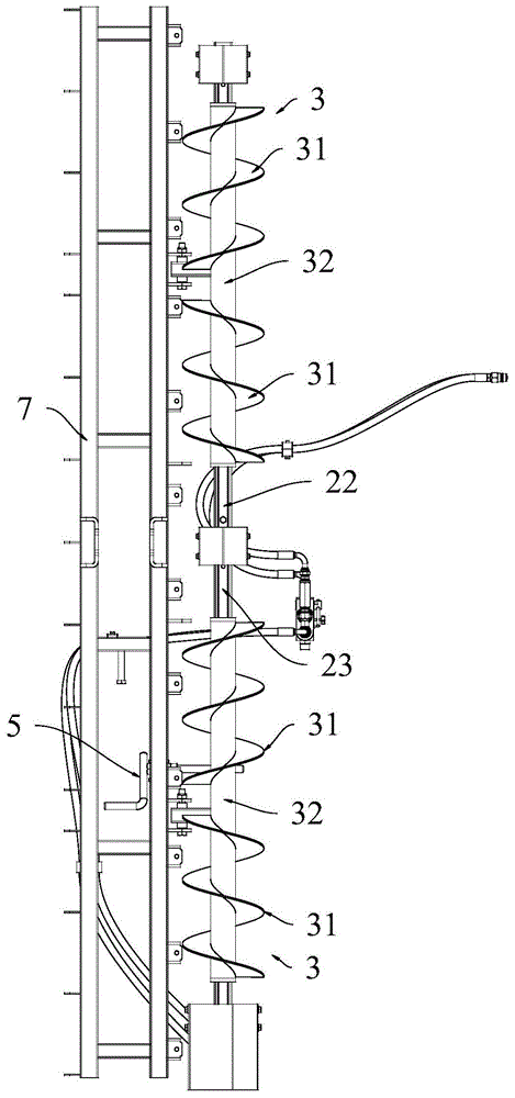
附图5为第二实施例之耕播机械用轮辙处理机构的结构图;Accompanying
附图6为第二实施例之耕播机械用轮辙处理机构的剖视图;Accompanying
附图7为松软度探测装置的结构图。FIG. 7 is a structural diagram of the softness detection device.
图中:1-搅龙支架;2-搅龙轴;21-方轴段;22-第一轴段;23-第二轴段;3-搅龙组件;31-螺旋部;32-中管部;321-圆管部;322-端板;33-顶紧螺钉;4-动力单元;41-液压马达;42-比例阀;5-调节机构;51-手柄座;52-调节手柄;53-螺套转节;6-牵引支架;7-主支架;8-浮动结构;81-第一连杆;82-第二连杆;83-第三连杆;84-第四连杆;85-过渡杆;86-转轴;87-拉簧;88-弹性连接器;881-弹簧筒;882-拉杆;883-压簧;9-松软度探测装置;91-装置架体;92-止推板;93-弹性减震器;94-位移传感器。In the figure: 1- auger support; 2- auger shaft; 21- square shaft segment; 22- first shaft segment; 23- second shaft segment; 3- auger assembly; 31- screw part; 32- middle pipe 321-round pipe part; 322-end plate; 33-top screw; 4-power unit; 41-hydraulic motor; 42-proportional valve; 5-adjustment mechanism; 51-handle seat; 52-adjustment handle; 53 -screw sleeve swivel; 6-traction bracket; 7-main bracket; 8-floating structure; 81-first link; 82-second link; 83-third link; 84-fourth link; 85 -Transition rod; 86-rotating shaft; 87-tension spring; 88-elastic connector; 881-spring cylinder; 882-tie rod; 883-compression spring; 9-softness detection device; 91-device frame; 92-thrust plate; 93 - elastic shock absorber; 94 - displacement sensor.
具体实施方式Detailed ways
下面结合附图对本发明作更进一步的说明。The present invention will be further described below in conjunction with the accompanying drawings.
如附图1与附图2所示的耕播机械用轮辙处理机构,其包括搅龙支架1、搅龙轴2、搅龙组件3以及动力单元4。As shown in FIG. 1 and FIG. 2 , the wheel track processing mechanism for tillage and seeding machinery includes an
其中,搅龙轴2相对于所述搅龙支架1转动安装,其转动由动力单元4驱动。所述动力单元4包括液压马达41,所述液压马达41通过油管连接比例阀42,所述比例阀42通过油管连接压力油源,压力油源包括油缸与油泵。液压马达41相对于传统电机,其更耐恶劣环境,适用于耕播这种场合,可靠性高,故障率低。通过比例阀42可调节液压马达41的运转速度。The
所述搅龙支架1上安装有三处转动支承结构,三处所述转动支承结构分别对所述搅龙轴2的两端及中央进行支承。上述转动支承结构具备轴承,如此不仅搅龙轴2可相对于搅龙支架1顺滑转动,而且搅龙轴2得到了有效的支承,其不会由于过长而产生弯曲。The
搅龙轴2的左右两侧对称安装有两组搅龙组件3,两组搅龙组件3分别位于处于中间的转动支承结构的两侧。如附图2所示,每个搅龙组件3包含两个对称设置的螺旋部31,且两个所述螺旋部31的螺旋方向相反;两个螺旋部31之间具有一定的间隔;每组所述搅龙组件3均可在所述搅龙轴2的长度方向上调节位置。Two sets of
上述结构中,两组搅龙组件3分别用于处理拖拉机等牵引机械产生的两道轮辙。对于同一搅龙组件3,使用时使两个螺旋部31之间的间隔对着牵引机械的轮子,如此牵引机械的轮子压出的轮辙位于两个螺旋部31之间,由于两个螺旋部31的螺旋方向相反,当搅龙轴2转动时,两个螺旋部31分别可从左、右两侧推动土地表层的浮土并将浮土汇聚到两个螺旋部31之间将轮辙填上,双向推动浮土有效提升了单位时间输入浮土的体积,可有效将轮辙填实。此外螺旋部31推动浮土运动的同时相当于将地表刮了一遍,可起到使土地进行初步平土的作用。由于搅龙组件3可在搅龙轴2的长度方向上调节位置,因此,当不同型号的牵引机械牵引农业耕播机械时,可预先根据牵引机械的轮距对两个搅龙组件3的位置进行调节,以使得搅龙组件3的中部对准轮辙达到最佳的处理效果,如此可大大提升对轮辙的处理效果,使得搅龙结构适应不同型号的牵引机械。In the above structure, the two groups of
优选地,所述搅龙轴2对应于每个所述搅龙组件3均设有方轴段21,所述搅龙组件3包括中管部32,所述中管部32套设在所述方轴段21上,且所述中管部32上安装有用于顶紧所述方轴段21外壁的顶紧螺钉33。需要调节搅龙组件3的位置时,仅需松开顶紧螺钉33并移动搅龙组件3,调节好位置后,将顶紧螺钉33拧紧使其端部顶住方轴段21,调节方便、结构简单、实现成本低。Preferably, the
具体地,如附图4所示,所述中管部32包括圆管部321,所述圆管部321的两端各固定有中心具有方孔的端板322;所述端板322中部的方孔与所述方轴段21滑动配合,如此,中管部32不需要设置将其整个贯穿的方形孔,仅依靠两个端板322上的方形孔就能达到导向以及传动扭矩的作用。Specifically, as shown in FIG. 4 , the
此外,所述搅龙轴2由第一轴段22与第二轴段23两个轴构成,两个轴传动连接,且两者分别置于中间的所述转动支承结构的两侧,第一轴段22与第二轴段23上均具备方轴段21,两个搅龙组件3分别安装在两个轴上。如此可降低搅龙轴2的加工与装配难度。In addition, the
在进一步的实施例中,由于土壤的松软程度不一,对于不同松软程度的土壤,需要调节螺旋部31的入土深度以达到较好的处理效果。因此,搅龙结构还包括主支架7,所述搅龙支架1转动安装在所述主支架7的前端,且所述搅龙支架1相对于所述主支架7的俯仰角度可通过调节机构5调节。In a further embodiment, since soils have different degrees of softness, for soils with different degrees of softness, it is necessary to adjust the depth of soil penetration of the
具体地,如附图3所示,所述主支架7上转动安装有手柄座51,所述手柄座51上转动安装有调节手柄52,所述调节手柄52具有螺杆部;所述搅龙支架1上转动安装有螺套转节53,所述螺杆部与所述螺套转节53呈螺纹副配合。通过该结构,通过摇动调节手柄52,可使螺杆部转动,使得螺套转节53相对于调节手柄52的尾部靠近或远离,以实现对搅龙支架1俯仰角度的调节。当土地越松软,拖拉机压出的轮辙越深,需要的浮土越多,需要将搅龙支架1调节得越低,螺旋部31的入土深度越深;反之,当土地越硬,拖拉机压出的轮辙越浅,需要的浮土越少,需要将搅龙支架1调节得越高,螺旋部31的入土深度越浅。Specifically, as shown in FIG. 3 , a
在更进一步的实施例中,由于拖拉机在不平整的土地上运动时其颠簸幅度较大,若直接将主支架7与拖拉机刚性连接,会导致搅龙支架1一端翘起的情况,如此搅龙组件3也就不能完全作用于土地。为了避免上述情况发生,在优选的第二实施例中,如附图5-6所示,搅龙机构还包括牵引支架6,所述主支架7通过浮动结构8连接所述牵引支架6,牵引支架6连接拖拉机等牵引机械。所述浮动结构8包括四连杆机构、弹性连接器88以及拉簧87。四连杆机构包括第一连杆81、第二连杆82、第三连杆83以及第四连杆84,且四连杆机构为平行四边形连杆结构。其中,第三连杆83固定在牵引支架6上;第一连杆81与第二连杆82平行设置,两者的两端均分别与第三连杆83以及第四连杆84转动连接。弹性连接器88安装在第一连杆81与牵引支架6之间以使得第一连杆81具有向下摆动运动的趋势。第四连杆84上固定连接有过渡杆85,所述主支架7的中部通过转轴86铰接在过渡杆85上,且转轴86的两侧对称设置有若干对拉簧87。In a further embodiment, since the tractor has a relatively large bump when it moves on uneven ground, if the
通过上述结构,可使得过渡杆85可在牵引支架6的后侧上下弹性浮动,且主支架7可相对于过渡杆85左右弹性摆动。如此主支架7可相对于牵引支架6上下弹性浮动以及左右弹性摆动,弹性连接器88与拉簧87的弹力使得主支架7可适应地形自行调节位姿,滤除牵引机械的颠簸振动,保证搅龙组件3及主支架7上安装的其他部件(如平土板、开槽器、出料管等,图中未示出)时刻作用于地面。Through the above structure, the
上述弹性连接器88包括弹簧筒881以及拉杆882;拉杆882的第一端置于弹簧筒881内,且其第二端可从弹簧筒881的第一端穿出。弹簧筒881与拉杆882之间设置有压簧883,压簧883使得拉杆882具有缩入弹簧筒881的运动趋势;拉杆882的第二端与弹簧筒881的第二端分别转动安装在牵引支架6与主支架7上。The above-mentioned
优选地,牵引支架6通过三点悬挂装置连接牵引机械,三点悬挂装置被液压举升油缸驱动相对于牵引机械升降,如此液压举升油缸可调节牵引支架6的升降,由于主支架7及其上安装有部件的自重关系,当牵引支架6在一定范围内升降时,主支架7不会随着升降,此时,当牵引支架6被液压举升油缸抬高,四连杆机构变形使得拉杆882与弹簧筒881产生相对位移,压簧883的预压缩量变大,压簧883的刚性即变大,如此过渡杆85及主支架7的上下浮动幅度变小;当牵引支架6被液压举升油缸降低,四连杆机构变形使得拉杆882与弹簧筒881产生相对位移,压簧883的预压缩量变小,压簧883的刚性即变小,如此过渡杆85及主支架7的上下浮动幅度变大。如此,通过液压举升油缸对压簧883的预压缩量进行调节,以调节主支架7的上下运动的浮动幅度,使得主支架7可适应不同松软度的土壤。当土壤越松软,液压举升油缸将所述牵引支架6降得越低;当土壤越硬,液压举升油缸将所述牵引支架6升的越高。Preferably, the
由于调节主支架7的弹性浮动幅度需要依赖用户的经验才能取得较好的效果,为了减少用户经验对轮辙处理质量的影响,可设置自动调节单元对主支架7的弹性浮动幅度进行自动调节,具体地,自动调节单元包括控制器,控制器与液压举升油缸控制连接,控制器可控制液压举升油缸的举升量,此外,控制器还连接用于探测泥土松软度的松软度探测装置9;所述松软度探测装置9安装在牵引主机上,且松软度探测装置9安装在牵引主机的车轮的侧边;如附图7所示,松软度探测装置9包括装置架体91与止推板92,所述止推板92始终与地面接触,所述装置架体91与止推板92之间设有弹性减震器93以及位移传感器94,所述位移传感器94连接控制器。通过上述松软度探测装置9,当拖拉机等牵引主机在田地中运动,由于拖拉机较重,可通过探测拖拉机压出的轮辙的深度作为泥土松软度的测量指标,采用上述结构,将松软度探测装置9设置在牵引主机的轮子侧边,止推板92可直接压紧轮子旁的地面,可以准确测得轮辙深度,由于弹性减震器93的压力作用,止推板92可起到将浮土压得较实的作用,使得测得的轮辙深度更具参考性,由于拖拉机在左右方向上可能歪斜,可在拖拉机左右轮子旁各设一组松软度探测装置9,控制器将采集得到的两个位移传感器94的值取平均数得到平均轮辙深度,控制器根据预设的平均轮辙深度与土壤松软度的对应关系曲线可得到土壤松软度,并根据预设的土壤松软度与液压举升油缸的位移关系曲线可得到液压举升油缸的目标位移量,再根据目标位移量驱动液压举升油缸运转,实现对主支架7的弹性浮动幅度的调节。优选地,上述松软度探测装置9中,弹性减震器93有两组,两组弹性减震器93设置在止推板92的前后两侧,位移传感器94置于止推板92的中部。Since adjusting the elastic floating range of the
同理,可对拉簧87的预拉伸量进行调节以调节主支架7的左右摆动幅度。Similarly, the pre-stretching amount of the
本发明的耕播机械用轮辙处理机构通过设置可调节搅龙支架相对于主支架俯仰角度的调节机构,使得搅龙组件上螺旋部的入土深度可调节,从而可根据不同松软程度的土壤调节螺旋部的入土深度以满足处理轮辙对浮土体积的需求,保证轮辙处理质量。The wheel rut treatment mechanism for tillage and seeding machinery of the present invention is provided with an adjustment mechanism that can adjust the pitch angle of the auger support relative to the main support, so that the depth of soil penetration of the screw part on the auger assembly can be adjusted, so that it can be adjusted according to soils with different degrees of softness The depth of soil penetration of the helical part can meet the requirements for the volume of regolith for the treatment of wheel ruts and ensure the quality of wheel rut treatment.
以上所述仅是本发明的优选实施方式,应当指出:对于本技术领域的普通技术人员来说,在不脱离本发明原理的前提下,还可以做出若干改进和润饰,这些改进和润饰也应视为本发明的保护范围。The above is only the preferred embodiment of the present invention, it should be pointed out that: for those skilled in the art, without departing from the principle of the present invention, several improvements and modifications can also be made, and these improvements and modifications are also It should be regarded as the protection scope of the present invention.
Claims (8)
Priority Applications (1)
| Application Number | Priority Date | Filing Date | Title |
|---|---|---|---|
| CN202010512425.6A CN111567160B (en) | 2020-06-08 | 2020-06-08 | Wheel track processing mechanism for tilling and sowing machinery |
Applications Claiming Priority (1)
| Application Number | Priority Date | Filing Date | Title |
|---|---|---|---|
| CN202010512425.6A CN111567160B (en) | 2020-06-08 | 2020-06-08 | Wheel track processing mechanism for tilling and sowing machinery |
Publications (2)
| Publication Number | Publication Date |
|---|---|
| CN111567160A true CN111567160A (en) | 2020-08-25 |
| CN111567160B CN111567160B (en) | 2021-06-25 |
Family
ID=72125724
Family Applications (1)
| Application Number | Title | Priority Date | Filing Date |
|---|---|---|---|
| CN202010512425.6A Active CN111567160B (en) | 2020-06-08 | 2020-06-08 | Wheel track processing mechanism for tilling and sowing machinery |
Country Status (1)
| Country | Link |
|---|---|
| CN (1) | CN111567160B (en) |
Cited By (2)
| Publication number | Priority date | Publication date | Assignee | Title |
|---|---|---|---|---|
| CN113303042A (en) * | 2021-04-15 | 2021-08-27 | 农业农村部南京农业机械化研究所 | Rut earthing device for agricultural machinery |
| CN118355747A (en) * | 2024-04-15 | 2024-07-19 | 农业农村部南京农业机械化研究所 | A wheel track covering mechanism capable of multi-dimensional adjustment |
Citations (9)
| Publication number | Priority date | Publication date | Assignee | Title |
|---|---|---|---|---|
| CN2103880U (en) * | 1991-10-18 | 1992-05-13 | 上海市嘉定县农县研究所 | Paddy field leveling machine |
| CN2371769Y (en) * | 1999-05-19 | 2000-04-05 | 殷志明 | Multifunctional three-shared mounted plough |
| CN203327496U (en) * | 2013-06-13 | 2013-12-11 | 四川农业大学 | Rice planter wheel imprint filling device |
| WO2016145490A1 (en) * | 2015-03-16 | 2016-09-22 | Tynab Pty Ltd | Wheel track renovator and method of use |
| CN205694135U (en) * | 2016-04-29 | 2016-11-23 | 汤本文 | Seeder is with taking off flat spin |
| CN206226934U (en) * | 2016-10-13 | 2017-06-09 | 青海省畜牧兽医科学院 | A kind of tractor bull wheel impression arrester |
| CN207443357U (en) * | 2017-10-20 | 2018-06-05 | 金塔县金农机械制造有限公司 | A kind of novel rotary cultivator |
| CN207476133U (en) * | 2017-11-04 | 2018-06-12 | 郁永田 | A kind of agricultural grader |
| CN208016266U (en) * | 2017-12-22 | 2018-10-30 | 河北锦禾农业机械有限公司 | A kind of rice transplanter rut covers leveling device |
-
2020
- 2020-06-08 CN CN202010512425.6A patent/CN111567160B/en active Active
Patent Citations (9)
| Publication number | Priority date | Publication date | Assignee | Title |
|---|---|---|---|---|
| CN2103880U (en) * | 1991-10-18 | 1992-05-13 | 上海市嘉定县农县研究所 | Paddy field leveling machine |
| CN2371769Y (en) * | 1999-05-19 | 2000-04-05 | 殷志明 | Multifunctional three-shared mounted plough |
| CN203327496U (en) * | 2013-06-13 | 2013-12-11 | 四川农业大学 | Rice planter wheel imprint filling device |
| WO2016145490A1 (en) * | 2015-03-16 | 2016-09-22 | Tynab Pty Ltd | Wheel track renovator and method of use |
| CN205694135U (en) * | 2016-04-29 | 2016-11-23 | 汤本文 | Seeder is with taking off flat spin |
| CN206226934U (en) * | 2016-10-13 | 2017-06-09 | 青海省畜牧兽医科学院 | A kind of tractor bull wheel impression arrester |
| CN207443357U (en) * | 2017-10-20 | 2018-06-05 | 金塔县金农机械制造有限公司 | A kind of novel rotary cultivator |
| CN207476133U (en) * | 2017-11-04 | 2018-06-12 | 郁永田 | A kind of agricultural grader |
| CN208016266U (en) * | 2017-12-22 | 2018-10-30 | 河北锦禾农业机械有限公司 | A kind of rice transplanter rut covers leveling device |
Cited By (2)
| Publication number | Priority date | Publication date | Assignee | Title |
|---|---|---|---|---|
| CN113303042A (en) * | 2021-04-15 | 2021-08-27 | 农业农村部南京农业机械化研究所 | Rut earthing device for agricultural machinery |
| CN118355747A (en) * | 2024-04-15 | 2024-07-19 | 农业农村部南京农业机械化研究所 | A wheel track covering mechanism capable of multi-dimensional adjustment |
Also Published As
| Publication number | Publication date |
|---|---|
| CN111567160B (en) | 2021-06-25 |
Similar Documents
| Publication | Publication Date | Title |
|---|---|---|
| US4430952A (en) | Planter gauge wheels with adjustable equalizer mechanism | |
| US20240032456A1 (en) | Trailing arm device and assembly with parallel linkage | |
| US4493274A (en) | Furrow forming apparatus for a seed planter | |
| CN103098590B (en) | Paddy field direct sowing machine synchronous in covering soil, ditching and ridging powered by wheeled tractor | |
| US4356780A (en) | Equalized furrow forming apparatus for a seed planter | |
| CN105594327A (en) | Land leveling system for paddy field rotary cultivator | |
| CN107318339B (en) | Driven cutting and pressing adjustment device for potato harvesters | |
| CN111587618B (en) | Live operation device of agricultural live broadcast machine | |
| CN111567160A (en) | A wheel track processing mechanism for tillage and sowing machinery | |
| CN204206734U (en) | Single-point hangs feeler mechanism | |
| CN203086954U (en) | Paddy field synchronous earthing, ditching and ridging direct seeding machine using roller tractor as power | |
| CN218868630U (en) | Combined rotary tillage seeding and fertilizing combined machine | |
| CN205623114U (en) | Suppress no -tillage seeder | |
| CN212650042U (en) | Sowing and fertilizing device for agricultural machinery | |
| CN222302366U (en) | A rice direct seeding machine | |
| CN209897599U (en) | Novel towed sesame seeder | |
| CN201504410U (en) | Traction type potato planter | |
| CN217905079U (en) | A soil-covering disc mechanism | |
| CN206294513U (en) | A kind of primary transmission precision cotton drilling device | |
| CN212650034U (en) | A mud auger structure of a tillage and sowing machine | |
| CN107787629A (en) | The two level guide wheel mechanism of the agriculture cultivated evener of pine | |
| CN211297592U (en) | Ridging ditching component and ridging ditching mechanism | |
| CN111567169A (en) | A ground conformal frame for agricultural tillage and sowing machinery | |
| CN114080880A (en) | Self-walking small corn seeder | |
| CN2819732Y (en) | Improved grain seeder |
Legal Events
| Date | Code | Title | Description |
|---|---|---|---|
| PB01 | Publication | ||
| PB01 | Publication | ||
| SE01 | Entry into force of request for substantive examination | ||
| SE01 | Entry into force of request for substantive examination | ||
| GR01 | Patent grant | ||
| GR01 | Patent grant | ||
| TR01 | Transfer of patent right | ||
| TR01 | Transfer of patent right |
Effective date of registration: 20221227 Address after: 251199 South, 300m west of the intersection of Qizhong Avenue and Mingjia West Road, Qihe Economic Development Zone, Dezhou, Shandong Patentee after: Shandong younia Agricultural Machinery Co.,Ltd. Address before: No. 100, Liuying, Zhongshan Gate, Xuanwu District, Nanjing, Jiangsu Province, 210000 Patentee before: NANJING Research Institute FOR AGRICULTURAL MECHANIZATION MINISTRY OF AGRICULTURE |
|
| PE01 | Entry into force of the registration of the contract for pledge of patent right | ||
| PE01 | Entry into force of the registration of the contract for pledge of patent right |
Denomination of invention: A wheel track processing mechanism for tillage and broadcasting machinery Granted publication date: 20210625 Pledgee: China Postal Savings Bank Co.,Ltd. Qihe County sub branch Pledgor: Shandong younia Agricultural Machinery Co.,Ltd. Registration number: Y2024980039947 |