CN111567155B - Heat radiator - Google Patents
Heat radiator Download PDFInfo
- Publication number
- CN111567155B CN111567155B CN201880076912.3A CN201880076912A CN111567155B CN 111567155 B CN111567155 B CN 111567155B CN 201880076912 A CN201880076912 A CN 201880076912A CN 111567155 B CN111567155 B CN 111567155B
- Authority
- CN
- China
- Prior art keywords
- heat sink
- heat
- fins
- radiation fin
- heat radiation
- Prior art date
- Legal status (The legal status is an assumption and is not a legal conclusion. Google has not performed a legal analysis and makes no representation as to the accuracy of the status listed.)
- Active
Links
Images


Classifications
-
- H—ELECTRICITY
- H05—ELECTRIC TECHNIQUES NOT OTHERWISE PROVIDED FOR
- H05K—PRINTED CIRCUITS; CASINGS OR CONSTRUCTIONAL DETAILS OF ELECTRIC APPARATUS; MANUFACTURE OF ASSEMBLAGES OF ELECTRICAL COMPONENTS
- H05K1/00—Printed circuits
- H05K1/02—Details
- H05K1/0201—Thermal arrangements, e.g. for cooling, heating or preventing overheating
- H05K1/0203—Cooling of mounted components
- H05K1/0209—External configuration of printed circuit board adapted for heat dissipation, e.g. lay-out of conductors, coatings
-
- H—ELECTRICITY
- H05—ELECTRIC TECHNIQUES NOT OTHERWISE PROVIDED FOR
- H05K—PRINTED CIRCUITS; CASINGS OR CONSTRUCTIONAL DETAILS OF ELECTRIC APPARATUS; MANUFACTURE OF ASSEMBLAGES OF ELECTRICAL COMPONENTS
- H05K7/00—Constructional details common to different types of electric apparatus
- H05K7/20—Modifications to facilitate cooling, ventilating, or heating
- H05K7/2039—Modifications to facilitate cooling, ventilating, or heating characterised by the heat transfer by conduction from the heat generating element to a dissipating body
- H05K7/20509—Multiple-component heat spreaders; Multi-component heat-conducting support plates; Multi-component non-closed heat-conducting structures
-
- H10W40/226—
-
- H10W40/60—
-
- H—ELECTRICITY
- H05—ELECTRIC TECHNIQUES NOT OTHERWISE PROVIDED FOR
- H05K—PRINTED CIRCUITS; CASINGS OR CONSTRUCTIONAL DETAILS OF ELECTRIC APPARATUS; MANUFACTURE OF ASSEMBLAGES OF ELECTRICAL COMPONENTS
- H05K2201/00—Indexing scheme relating to printed circuits covered by H05K1/00
- H05K2201/06—Thermal details
- H05K2201/066—Heatsink mounted on the surface of the printed circuit board [PCB]
Landscapes
- Engineering & Computer Science (AREA)
- Microelectronics & Electronic Packaging (AREA)
- Physics & Mathematics (AREA)
- Thermal Sciences (AREA)
- Cooling Or The Like Of Electrical Apparatus (AREA)
- Shielding Devices Or Components To Electric Or Magnetic Fields (AREA)
- Cooling Or The Like Of Semiconductors Or Solid State Devices (AREA)
- Chemical & Material Sciences (AREA)
- Materials Engineering (AREA)
- Condensed Matter Physics & Semiconductors (AREA)
- General Physics & Mathematics (AREA)
- Computer Hardware Design (AREA)
- Power Engineering (AREA)
Abstract
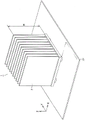
散热器(1)具备基部(3)、间隙确保构件(5)、散热片(7)以及上部金属板(9)。散热片(7)分别在X方向上具有宽度(W),在Z方向上延伸而具有长度(H)。散热片(7)分别具有隔开长度(H)地对置的第1端部(7a)以及第2端部(7b)。散热片(7)的第1端部(7a)被固定于基部(3),第2端部(7b)侧设为开放端侧。以使一个散热片(7)的第2端部(7b)与另一散热片(7)的第2端部(7b)连接的形态将上部金属板(9)连接于散热片(7)的第2端部(7b)。上部金属板(9)在Y方向上延伸。

The heat sink (1) includes a base (3), a gap securing member (5), a heat sink (7), and an upper metal plate (9). The fins (7) each have a width (W) in the X direction, and extend in the Z direction to have a length (H). The fins (7) each have a first end portion (7a) and a second end portion (7b) opposed to each other at a distance (H) from each other. The first end portion (7a) of the heat sink (7) is fixed to the base portion (3), and the second end portion (7b) side is defined as the open end side. The upper metal plate (9) is connected to the heat sink (7) in such a manner that the second end (7b) of one heat sink (7) is connected to the second end (7b) of the other heat sink (7). The second end (7b). The upper metal plate (9) extends in the Y direction.
Description
技术领域technical field
本发明涉及散热器,特别涉及具备散热片的散热器。The present invention relates to a heat sink, in particular to a heat sink provided with cooling fins.
背景技术Background technique
近年来,伴随电子设备的显著的高密度化或者高频化,在中央运算处理装置(CPU:Central Processing Unit,中央处理单元)所代表的大规模集成电路(LSI:Large-ScaleIntegration)等电子部件中,从电子部件产生的热成为设计时的担忧事项。为了使从电子部件产生的热消散,充分地利用散热器。In recent years, with the significant increase in density or frequency of electronic equipment, electronic components such as large-scale integrated circuits (LSI: Large-Scale Integration) represented by central processing units (CPU: Central Processing Unit, central processing unit) Among them, heat generated from electronic components becomes a concern at the time of design. In order to dissipate heat generated from electronic components, a heat sink is fully utilized.
能够利用散热器使所产生的热消散,另一方面,散热器有时因使热消散的散热片的长度所引起的波长的频率而发生电共振。以往,系统的时钟信号的频率对散热器造成电性的影响是有限制的。The generated heat can be dissipated by the heat sink. On the other hand, the heat sink may electrically resonate at a frequency of a wavelength due to the length of the fins that dissipate the heat. In the past, the frequency of the clock signal of the system has limited electrical impact on the heat sink.
然而,在近年的系统中,多时钟信号且高频化发展,散热器作为电磁噪声的放射源进行动作。即,有时印刷基板的噪声传导到散热器,或者,噪声例如由于印刷基板上的部件或者布线与散热器的耦合而重叠到散热器,散热器作为天线进行动作,使噪声二次辐射,从而产生系统的误动作。However, in recent systems, multiple clock signals and higher frequencies have been developed, and heat sinks operate as radiation sources of electromagnetic noise. That is, the noise of the printed board may be conducted to the heat sink, or the noise may be superimposed on the heat sink due to the coupling of parts or wiring on the printed board and the heat sink, and the heat sink acts as an antenna to radiate the noise twice, thereby generating System malfunction.
另外,有时散热器不仅作为噪声的放射源进行动作,有时还作为良好的噪声的接收天线进行动作。因此,有时无法满足各种EMC(Electro-Magnetic Compatibility,电磁兼容性)认证试验的标准值。因此,在散热器的设计中,不仅要求确保作为本来的目的的散热性,还要求考虑了电磁噪声的设计,提出了各种建议。In addition, the radiator may not only operate as a noise radiation source, but also may operate as a good noise receiving antenna. Therefore, standard values of various EMC (Electro-Magnetic Compatibility, electromagnetic compatibility) certification tests may not be satisfied. Therefore, in the design of the heat sink, not only securing the heat dissipation performance which is the original purpose, but also a design in consideration of electromagnetic noise is required, and various proposals have been made.
例如,在专利文献1中,提出了一种散热器,该散热器被设定成使散热片的长度与系统的信号频率或者该信号频率的高次谐波频率的1/2波长的长度不一致。另外,在专利文献2中,提出了具备使共振频率分散的散热片的散热器。For example, in
现有技术文献prior art literature
专利文献patent documents
专利文献1:日本特开2000-156578号公报(日本专利第3008942号公报)Patent Document 1: Japanese Patent Laid-Open No. 2000-156578 (Japanese Patent No. 3008942)
专利文献2:日本特开2000-305273号公报Patent Document 2: Japanese Patent Laid-Open No. 2000-305273
发明内容Contents of the invention
如上所述,在近年的系统中,利用大量的时钟信号进行动作。另外,根据各种数字I/F(Inter Face,接口)的基本频率进行数据的收发。因此,成为难以以与时钟信号等基准信号或者其高次谐波频率不一致的方式设计散热片的长度的状况。As described above, in recent systems, operations are performed using a large number of clock signals. In addition, data is transmitted and received based on the basic frequency of various digital I/F (Inter Face, interface). Therefore, it becomes difficult to design the length of the heat sink so as not to match the frequency of a reference signal such as a clock signal or its harmonic frequency.
具体而言,在散热片的长度短的情况下,有时损害作为散热器的本来的目的即散热性。另一方面,在散热片的长度变长的情况下,有时需要例如对框体进行重新设计等。因此,在专利文献1提出的散热器中,当想要实现确保散热性和降低电磁噪声这双方时,预计设计上的制约增加,难以进行自由度高的设计。Specifically, when the length of the heat sink is short, the heat dissipation performance which is the original purpose of the heat sink may be impaired. On the other hand, when the length of the heat sink becomes longer, it may be necessary to redesign the housing, for example. Therefore, in the heat sink proposed in
另一方面,在专利文献2提出的散热器中,需要设计长度及金属材料不同的散热片,所以预计散热器的设计和制造变得复杂。On the other hand, in the heat sink proposed in Patent Document 2, heat sinks having different design lengths and metal materials are required, so that design and manufacture of the heat sink are expected to become complicated.
本发明是鉴于上述问题点而完成的,其目的在于提供一种散热器,该散热器实现设计的自由度且实现电磁噪声的降低。The present invention has been made in view of the above-mentioned problems, and an object of the present invention is to provide a heat sink that achieves a degree of freedom in design and reduces electromagnetic noise.
本发明的散热器具有基部和多个散热片。基部搭载于印刷基板,电连接于印刷基板的信号接地电位、框架接地电位以及地线中的任意方。多个散热片相互隔开间隔地配置于基部,与基部电连接。在多个散热片中的与被安装于基部的一侧相反一侧的开放端侧,多个散热片中的一个散热片的一部分与另一散热片的一部分通过导电性构件电连接。The heat sink of the present invention has a base and a plurality of fins. The base is mounted on the printed circuit board, and is electrically connected to any one of the signal ground potential, the frame ground potential, and the ground of the printed circuit board. A plurality of cooling fins are arranged on the base at intervals, and are electrically connected to the base. A part of one of the plurality of heat sinks is electrically connected to a part of the other heat sink through a conductive member at an open end side opposite to the side attached to the base of the plurality of heat sinks.
根据本发明的散热器,在多个散热片中的开放端侧,多个散热片中的一个散热片的一部分与另一散热片的一部分通过导电性构件电连接。由此,在散热器中,能够降低多个散热片的开放端侧的阻抗,并且能够使电磁噪声返回到印刷基板的信号接地电位、框架接地电位以及地线中的任意方。其结果,作为散热器,不会受到电磁波的波长的制约,另外不会受到散热片的材料的制约,能够实现设计的自由度,且能够降低电磁噪声的强度。According to the heat sink of the present invention, on the open end side of the plurality of fins, a part of one of the plurality of fins is electrically connected to a part of the other fin through the conductive member. Accordingly, in the heat sink, the impedance of the open end sides of the plurality of heat sinks can be reduced, and electromagnetic noise can be returned to any one of the signal ground potential, the frame ground potential, and the ground line of the printed circuit board. As a result, the heat sink is not restricted by the wavelength of electromagnetic waves, and is not restricted by the material of the heat sink, so that the degree of freedom in design can be realized and the intensity of electromagnetic noise can be reduced.
附图说明Description of drawings
图1是示出本发明的实施方式1的散热器搭载于印刷基板的状态的一个例子的立体图。1 is a perspective view showing an example of a state where a heat sink according to
图2是示出在该实施方式中散热器搭载于印刷基板的状态的一个例子的侧视图。FIG. 2 is a side view showing an example of a state in which a heat sink is mounted on a printed circuit board in this embodiment.
图3是示出该实施方式中散热片与上部金属板的连接形态的局部放大立体图。Fig. 3 is a partially enlarged perspective view showing a connection form of a heat sink and an upper metal plate in the embodiment.
图4是示出比较例的散热器搭载于印刷基板的状态的立体图。4 is a perspective view showing a state in which a heat sink of a comparative example is mounted on a printed circuit board.
图5是示出本发明的实施方式2的散热器搭载于印刷基板的状态的一个例子的立体图。5 is a perspective view showing an example of a state where a heat sink according to Embodiment 2 of the present invention is mounted on a printed circuit board.
图6是示出本发明的实施方式3的第1例的散热器搭载于印刷基板的状态的一个例子的立体图。6 is a perspective view showing an example of a state in which a heat sink according to a first example of
图7是该实施方式中散热片的局部放大立体图。Fig. 7 is a partial enlarged perspective view of the heat sink in this embodiment.
图8是示出该实施方式中散热片与突起部的连接形态的局部放大立体图。FIG. 8 is a partially enlarged perspective view showing a connection form of a heat sink and a protrusion in this embodiment.
图9是示出本发明的实施方式3的第2例的散热器搭载于印刷基板的状态的一个例子的立体图。9 is a perspective view showing an example of a state where a heat sink according to a second example of
图10是示出该实施方式中散热片与突起部的连接形态的局部放大立体图。FIG. 10 is a partially enlarged perspective view showing a connection form of a heat sink and a protrusion in this embodiment.
图11是示出本发明的实施方式4的散热器搭载于印刷基板的状态的一个例子的立体图。11 is a perspective view showing an example of a state where a heat sink according to Embodiment 4 of the present invention is mounted on a printed circuit board.
图12是示出在该实施方式中连接构件的一个例子的放大立体图。FIG. 12 is an enlarged perspective view showing an example of a connection member in this embodiment.
图13是示出该实施方式中连接构件的其它例子的放大立体图。Fig. 13 is an enlarged perspective view showing another example of the connection member in this embodiment.
图14是示出本发明的实施方式5的散热器搭载于印刷基板的状态的一个例子的立体图。14 is a perspective view showing an example of a state where a heat sink according to
(附图标记说明)(Description of Reference Signs)
1:散热器;3:基部;5:间隙确保构件;7:散热片;7a:第1端部;7b:第2端部;7bb:上端面;7c:第3端部;7d:第4端部;9;11:上部金属板;13、15:突起部;13a、15a:跨接部;13b、15b:开口部;13c、15c:卡合部;17:连接构件;17a:跨接部;17b:卡合部;19:侧面金属板;51:印刷基板;53:放热部件;55:接地布线。1: radiator; 3: base; 5: gap securing member; 7: fin; 7a: first end; 7b: second end; 7bb: upper end; 7c: third end; 7d: fourth End; 9; 11: upper metal plate; 13, 15: protrusion; 13a, 15a: bridging portion; 13b, 15b: opening; 13c, 15c: engaging portion; 17: connecting member; 17a:
具体实施方式Detailed ways
实施方式1.
说明实施方式1的散热器。The radiator of
如图1以及图2所示,散热器1例如搭载于印刷基板51。在印刷基板51安装有电子部件53。散热器1被配置成与电子部件53接触。从大规模集成电路等电子部件53产生的热经由散热器1消散。详细地说明该散热器1的构造。As shown in FIGS. 1 and 2 , the
散热器1具备基部3、间隙确保构件5、多个散热片7以及作为导电性构件的上部金属板9。基部3为平板状,具有一定的厚度。间隙确保构件5确保基部3与印刷基板51的间隔以使基部3与电子部件53接触或者接近。此外,在无法应用金属制的间隙确保构件5的情况下,也可以另外设置螺钉、板上触点(on-board contact)或者垫片等导电性的构件,从而使基部3与印刷基板51电连接。The
多个散热片7分别在X方向上具有宽度W,在Z方向上延伸,具有长度H。多个散热片7分别具有隔开长度H而对置的第1端部7a和第2端部7b。多个散热片7在Y方向上相互隔开间隔地配置于基部3。散热片7的第1端部7a固定于基部3。散热片7的第2端部7b侧成为开放端侧。Each of the plurality of
多个散热片7由导热率高且导电性高的相同的金属材料形成。另外,多个散热片7最好由相同尺寸形成。此外,相同尺寸并不意味着完全相同,包含制造上的误差。散热片7最好由例如铝、铝合金或者铜等形成。The plurality of
以使相互相邻的一个散热片7的第2端部7b与另一散热片7的第2端部7b连接的形态将上部金属板9连接于多个散热片7的第2端部7b。上部金属板9在Y方向上延伸。此外,即使在一个散热片7与另一散热片7未相互相邻的情况下,作为多个散热片7的整体,也只要开放端侧通过上部金属板9电连接即可。The
与散热片7同样地,基部3、间隙确保构件5以及上部金属板9最好由导热率高且导电性高的金属材料形成,例如由铝、铝合金或者铜等形成。Like the
多个散热片7的开放端侧通过上部金属板9电连接。在散热片7的开放端侧,上部金属板9需要至少在一个部位处连接。为了降低散热片7的阻抗,最好在散热片7的多个部位处通过上部金属板9连接。另外,如后所述,还最好增宽上部金属板9的宽度。在此,如图3所示,两个上部金属板9连接于第2端部7b的端面7bb。Open end sides of the plurality of
上部金属板9例如通过焊接或者利用具有导电性的粘接剂连接于散热片7的第2端部7b。另外,也可以通过一体化成型形成上部金属板9和散热片7。The
多个散热片7经由基部3以及间隙确保构件5而例如与形成于印刷基板51的接地布线55电连接。基部3(间隙确保构件5)与接地布线55需要至少在一个部位处连接。为了降低散热器1相对于接地布线55的接地电位(地线)的阻抗,基部3与接地布线55最好在多个部位处连接。The plurality of
此外,在各实施方式中,将多个散热片7与接地布线55(地线)电连接的情况举为一个例子而进行说明,但多个散热片7电连接于接地电位即可。接地电位因搭载散热器的系统的接地设计而不同,有信号接地电位、框架接地电位以及地线。信号接地电位是指作为电路的基准的接地电位。框架接地电位是指包括散热器1的框体的接地电位。因而,多个散热片7电连接于信号接地电位、框架接地电位以及地线中的任意方即可。In addition, in each embodiment, the case where the plurality of
在上述散热器1中,多个散热片7的开放端侧通过上部金属板9电连接。由此,能够降低电磁噪声的强度。关于该情况,与比较例的散热器进行比较而进行说明。In the
在图4中,作为比较例的散热器,示出未配置上部金属板的一般的散热器1。在此,将比较例的散热器1的散热片7的Z方向的长度设为H,将电磁波的波长设为λ。于是,认为散热器1(多个散热片7)与在与λ=4L对应的频率和该频率的奇数倍的频率处产生共振的λ/4单极天线等效。从散热片7放射在与该波长相应的频率和其高次谐波频率处频谱强度高的电磁噪声。In FIG. 4 , a
相对于比较例,在实施方式1的散热器1中,多个散热片7的开放端侧通过上部金属板9电连接。另外,多个散热片7经由基部3以及间隙确保构件5而与印刷基板51的接地布线55电连接。In contrast to the comparative example, in the
因此,在散热器1中,能够降低多个散热片7的开放端侧的阻抗。进而,能够使传导到散热器1的电磁噪声经由基部3以及间隙确保构件5返回到地线。Therefore, in the
由此,即便散热片7的长度H为如与λ/4单极天线等效那样的尺寸关系,也能够抑制电磁噪声的放射,降低电磁噪声的强度。即,作为散热器1,不会受到电磁波的波长的制约,另外,不会受到散热片7的材料的制约,能够实现设计的自由度且降低电磁噪声的强度。Thereby, even if the length H of the
另外,当在比较例的散热器1中进行强制空气冷却的情况下,设想以与散热片7对置的方式配置风扇(未图示)的情况。在该情况下,有时由于由风扇产生的空气的流动而散热片7振动,该振动经由印刷基板传递到电子部件。In addition, when forced air cooling is performed in the
相对于比较例,在实施方式1的散热器1中,多个散热片7的开放端侧通过上部金属板9电性地且物理性地连接。由此,即便因风扇(未图示)而产生空气的流动,作为由上部金属板9带来的附属效果,也能够抑制散热片7的振动。In contrast to the comparative example, in the
实施方式2.Implementation mode 2.
说明实施方式2的散热器。A heat sink according to Embodiment 2 will be described.
如图5所示,作为导电性构件,宽度宽的上部金属板11配置于散热器1。以使相互相邻的一个散热片7的第2端部7b与另一散热片7的第2端部7b连接的形态,以从散热片7的第2端部7b的X方向上的一端横跨到另一端且堵塞开放端侧的一个散热片7与另一散热片7之间的空隙的方式配置上部金属板11。As shown in FIG. 5 , a wide upper metal plate 11 is arranged on the
上部金属板11例如通过焊接或者利用具有导电性的粘接剂连接于散热片7的第2端部7b。另外,也可以使上部金属板11与基部3以及散热片7一起通过一体成型形成。此外,关于除此以外的结构,与图1等所示的散热器1的结构相同,所以对相同构件附加相同的附图标记,除了必要的情况,不重复其说明。The upper metal plate 11 is connected to the
在上述散热器1中,被配置成宽幅的上部金属板11从散热片7的第2端部7b的X方向上的一端横跨到另一端且堵塞开放端侧。因此,与宽度窄的上部金属板9(图1等)相比,能够更加降低散热片7的开放端侧的阻抗。另外,如前所述,能够使传导到散热器1的电磁噪声经由基部3以及间隙确保构件5返回到地线。In the
由此,即便散热片7的长度H为如与λ/4单极天线等效那样的尺寸,也能够可靠地抑制电磁噪声的放射,降低电磁噪声的强度。Accordingly, even if the length H of the
即,在实施方式2的散热器1中,不会受到电磁波的波长的制约,另外,不会受到散热片7的材料的制约,能够实现设计的自由度,且能够降低电磁噪声的强度。That is, in the
另外,与实施方式1的散热器1同样地,在实施方式2的散热器1中,多个散热片7的开放端侧通过上部金属板11电性地且物理性地连接。由此,即便因风扇(未图示)而产生空气的流动,作为由上部金属板11带来的附属效果,也能够抑制散热片7的振动。In addition, like the
实施方式3.
(第1例)(1st case)
说明实施方式3的散热器的第1例。A first example of the heat sink according to
如图6所示,作为导电性构件,宽度比较窄的突起部13配置于散热器1。如图7所示,突起部13以向Y方向突出的方式设置于散热片7的第2端部7b。在突起部13例如设置有跨接部13a、开口部13b以及卡合部13c。As shown in FIG. 6 , as a conductive member, a
如图8所示,跨接部13a被配置成跨接相互相邻的一个散热片7与另一散热片7之间。将一个散热片7的突起部13的卡合部13c插入到另一散热片7的突起部13的开口部13b,从而突起部13彼此铆接,一个散热片与另一散热片相互卡合。以下,同样地,多个散热片7的开放端侧相互卡合。此外,关于除此以外的结构,与图1等所示的散热器1的结构相同,所以对相同构件附加相同的附图标记,除了必要的情况,不重复其说明。As shown in FIG. 8 , the bridging
在上述散热器1中,利用宽度比较窄的突起部13而多个散热片7的开放端侧相互卡合。因此,能够降低散热片7的开放端侧的阻抗。另外,如在实施方式1中说明那样,能够使传导到散热器1的电磁噪声经由基部3以及间隙确保构件5返回到地线。In the
由此,即便散热片7的长度H为如与λ/4单极天线等效那样的尺寸,也能够抑制电磁噪声的放射,降低电磁噪声的强度。Accordingly, even if the length H of the
即,在实施方式3的第1例的散热器1中,不会受到电磁波的波长的制约,另外,不会受到散热片7的材料的制约,能够实现设计的自由度且降低电磁噪声的强度。That is, in the
另外,与实施方式1的散热器1同样地,在实施方式3的第1例的散热器1中,多个散热片7的开放端侧通过突起部13电性地且物理性地连接。由此,即便因风扇(未图示)而产生空气的流动,作为由突起部13带来的附属效果,也能够抑制散热片7的振动。In addition, similar to the
此外,在上述散热器1中,将在X方向上相互隔开间隔地设置有两个突起部13的情况举为例子,但作为突起部13,在X方向的所期望的位置处至少设置有1个即可。In addition, in the above-mentioned
(第2例)(case 2)
说明实施方式3的散热器的第2例。A second example of the heat sink according to
如图9所示,作为导电性构件,宽度比较宽的突起部15配置于散热器1。如图10所示,突起部15以向Y方向突出的方式设置于散热片7的第2端部7b。在突起部15例如设置有跨接部15a、开口部15b以及卡合部15c。As shown in FIG. 9 , as a conductive member, a
跨接部15a被配置成跨接相互相邻的一个散热片7与另一散热片7之间。跨接部15a以从散热片7的第2端部7b的X方向上的一端横跨到另一端且堵塞开放端侧的一个散热片7与另一散热片7之间的空隙的方式配置。The bridging
将一个散热片7的突起部15的卡合部15c插入到另一散热片7的突起部15的开口部15b,从而突起部15彼此铆接,一个散热片与另一散热片相互卡合。以下,同样地,多个散热片7的开放端侧相互卡合。此外,关于除此以外的结构,与图1等所示的散热器1的结构相同,所以对相同构件附加相同的附图标记,除了必要的情况,不重复其说明。By inserting the engaging
在上述散热器1中,以利用宽度比较宽的突起部15来堵塞多个散热片7的开放端侧的方式,多个散热片7的开放端侧相互卡合。由此,能够更加降低散热片7的开放端侧的阻抗。另外,如在实施方式1中说明那样,能够使传导到散热器1的电磁噪声经由基部3以及间隙确保构件5返回到地线。In the
由此,即便散热片7的长度H为如与λ/4单极天线等效那样的尺寸,也能够可靠地抑制电磁噪声的放射,降低电磁噪声的强度。Accordingly, even if the length H of the
即,在实施方式3的第2例的散热器1中,不会受到电磁波的波长的制约,另外,不会受到散热片7的材料的制约,能够实现设计的自由度且降低电磁噪声的强度。That is, in the
另外,与实施方式1的散热器1同样地,在实施方式3的第2例的散热器1中,多个散热片7的开放端侧通过突起部13电性地且物理性地连接。由此,即便因风扇(未图示)而产生空气的流动,作为由突起部13带来的附属效果,也能够抑制散热片7的振动。In addition, similarly to the
实施方式4.Implementation mode 4.
说明实施方式4的散热器。A heat sink according to Embodiment 4 will be described.
如图11所示,作为导电性构件,连接构件17配置于散热器1。图12示出连接构件17的一个例子。图12所示的连接构件17设置有跨接部17a、卡合部17b以及卡合部17c。As shown in FIG. 11 , connecting
如图11以及图12所示,连接构件17被配置成跨接相互相邻的一个散热片7与另一散热片7之间。跨接部17a被配置成跨接一个散热片7与另一散热片7之间。卡合部17b卡合一个散热片7,卡合部17c卡合另一散热片7。As shown in FIG. 11 and FIG. 12 , the connecting
多个连接构件17配置于不相互干扰的X方向位置。此外,关于除此以外的结构,与图1等所示的散热器1的结构相同,所以对相同构件附加相同的附图标记,除了必要的情况,不重复其说明。The plurality of
在上述散热器1中,多个散热片7的开放端侧利用连接构件17相互卡合。因此,能够更加降低散热片7的开放端侧的阻抗。另外,如前所述,能够使传导到散热器1的电磁噪声经由基部3以及间隙确保构件5返回到地线。In the
由此,即便散热片7的长度H为如与λ/4单极天线等效那样的尺寸,也能够可靠地抑制电磁噪声的放射,降低电磁噪声的强度。Accordingly, even if the length H of the
即,在实施方式4的散热器1中,不会受到电磁波的波长的制约,另外,不会受到散热片7的材料的制约,能够实现设计的自由度且降低电磁噪声的强度。That is, in the
另外,与实施方式1的散热器1同样地,在实施方式4的散热器1中,多个散热片7的开放端侧通过突起部13电性地且物理性地连接。由此,即便因风扇(未图示)而产生空气的流动,作为由连接构件17带来的附属效果,也能够抑制散热片7的振动。In addition, like the
此外,作为连接构件17,除了可以为图12所示的连接构件17之外,例如也可以如图13所示为卡合部17b与卡合部17c对称地配置的连接构件17。In addition, as the
实施方式5.
说明实施方式5的散热器。A heat sink according to
如图14所示,作为导电性构件,一对侧面金属板19配置于散热器1。多个散热片7分别具有隔着宽度W而对置的第3端部7c和第4端部7d。一对侧面金属板19中的一方的侧面金属板19配置于多个散热片7各自的第3端部7c处的位于开放端侧的部分。另一方的侧面金属板19配置于多个散热片7各自的第4端部7d处的位于开放端侧的部分。As shown in FIG. 14 , a pair of
在此,一方的侧面金属板19从第3端部7c的与第2端部7b连结的部分以所期望的宽度向第1端部7a侧配置。另一方的侧面金属板19也从第4端部7d的与第2端部7b连结的部分以所期望的宽度向第1端部7a侧配置。侧面金属板19例如通过焊接或者利用具有导电性的粘接剂连接于散热片7的第3端部7c和第4端部7d。此外,关于除此以外的结构,与图1等所示的散热器1的结构相同,所以对相同构件附加相同的附图标记,除了必要的情况,不重复其说明。Here, one
在上述散热器1中,多个散热片7的第3端部7c与第4端部7d通过侧面金属板19电连接。因此,能够降低散热片7的开放端侧的阻抗。另外,如前所述,能够使传导到散热器1的电磁噪声经由基部3以及间隙确保构件5返回到地线。In the
由此,即便散热片7的长度H为如与λ/4单极天线等效那样的尺寸,也能够可靠地抑制电磁噪声的放射,降低电磁噪声的强度。Accordingly, even if the length H of the
即,在实施方式5的散热器1中,不会受到电磁波的波长的制约,另外不会受到散热片7的材料的制约,能够实现设计的自由度,且能够降低电磁噪声的强度。That is, in the
此外,侧面金属板19为上部金属板9、11等的替代,所以作为配置侧面金属板19的位置,最好为散热片7的第3端部7c以及第4端部7d各自的上部。Since the
根据降低散热片7的阻抗的观点,一般认为即使将侧面金属板19配置于散热片7的第3端部7c以及第4端部7d各自的中央部,也能够得到降低电磁噪声的效果。因而,作为配置侧面金属板19的位置,最好为散热片7的第3端部7c以及第4端部7d各自的中央部至上端部的范围内。From the viewpoint of reducing the impedance of the
另外,与实施方式1的散热器1同样地,在实施方式5的散热器1中,多个散热片7的开放端侧通过侧面金属板19电性地且物理性地连接。由此,即便因风扇(未图示)而产生空气的流动,作为由侧面金属板19带来的附属效果,也能够抑制散热片7的振动。In addition, similarly to the
此外,在各实施方式中,作为导电性构件,主要将板状的构件举为例子而进行了说明,但只要能够使多个散热片电连接,就不限于板状的构件,例如,也可以为具有导电性的带状的构件。In addition, in each embodiment, as a conductive member, a plate-shaped member is mainly taken as an example and described, but as long as a plurality of heat sinks can be electrically connected, it is not limited to a plate-shaped member, for example, may be It is a conductive strip-shaped member.
关于在各实施方式中说明的、具备作为导电性构件的上部金属板等的散热器1,能够根据需要进行各种组合。Various combinations are possible as necessary regarding the
本次公开的实施方式是例示,并不限于此。本发明不是通过在上述中说明的范围示出,而是通过权利要求示出,意图包含与权利要求等同的意义以及范围的所有的变更。Embodiment disclosed this time is an illustration, and is not limited to this. The present invention is shown not by the range described above but by the claims, and it is intended that all changes within the meanings and ranges equivalent to the claims are included.
工业上的可利用性Industrial availability
本发明有效地用于具备多个散热片的散热器。The present invention is effectively used for a heat sink provided with a plurality of fins.
Claims (4)
Applications Claiming Priority (1)
| Application Number | Priority Date | Filing Date | Title |
|---|---|---|---|
| PCT/JP2018/000746 WO2019138564A1 (en) | 2018-01-15 | 2018-01-15 | Heat-sink |
Publications (2)
| Publication Number | Publication Date |
|---|---|
| CN111567155A CN111567155A (en) | 2020-08-21 |
| CN111567155B true CN111567155B (en) | 2022-11-08 |
Family
ID=67218536
Family Applications (1)
| Application Number | Title | Priority Date | Filing Date |
|---|---|---|---|
| CN201880076912.3A Active CN111567155B (en) | 2018-01-15 | 2018-01-15 | Heat radiator |
Country Status (5)
| Country | Link |
|---|---|
| JP (1) | JP7004746B2 (en) |
| KR (1) | KR102434571B1 (en) |
| CN (1) | CN111567155B (en) |
| TW (1) | TWI664896B (en) |
| WO (1) | WO2019138564A1 (en) |
Families Citing this family (1)
| Publication number | Priority date | Publication date | Assignee | Title |
|---|---|---|---|---|
| JP2025150877A (en) * | 2024-03-27 | 2025-10-09 | 株式会社デンソー | electronic equipment |
Citations (2)
| Publication number | Priority date | Publication date | Assignee | Title |
|---|---|---|---|---|
| JPH09139592A (en) * | 1995-11-15 | 1997-05-27 | Nec Corp | Heat dissipation structure of electronic device |
| JP2003249611A (en) * | 2002-02-26 | 2003-09-05 | Fujikura Ltd | Finned heat sink |
Family Cites Families (18)
| Publication number | Priority date | Publication date | Assignee | Title |
|---|---|---|---|---|
| JPH0621251Y2 (en) * | 1989-01-26 | 1994-06-01 | 三菱アルミニウム株式会社 | Heat sink for electric element |
| JPH02132993U (en) * | 1989-04-07 | 1990-11-05 | ||
| JPH09116061A (en) * | 1995-10-13 | 1997-05-02 | Mitsubishi Materials Corp | Cooling device for electronic components |
| JP2000305273A (en) | 1998-11-19 | 2000-11-02 | Applied Materials Inc | Deep UV dry photolithography |
| JP3008942B1 (en) | 1998-11-20 | 2000-02-14 | 日本電気株式会社 | Heat dissipation structure of electronic device |
| JP4063025B2 (en) * | 2002-09-19 | 2008-03-19 | ティアック株式会社 | heatsink |
| US7408778B2 (en) * | 2006-09-11 | 2008-08-05 | International Business Machines Corporation | Heat sinks for dissipating a thermal load |
| JP2007281504A (en) | 2007-06-04 | 2007-10-25 | Fujikura Ltd | Heat sink and fin module |
| CN101325862A (en) * | 2008-08-01 | 2008-12-17 | 北京星网锐捷网络技术有限公司 | Cabinet, radiating device and method for installing the radiating device |
| US20120132400A1 (en) * | 2009-08-07 | 2012-05-31 | Furukawa-Sky Aluminum Corp. | Heat Sink |
| JP5236772B2 (en) * | 2011-04-18 | 2013-07-17 | 株式会社ソニー・コンピュータエンタテインメント | Heat sink and electronic device including heat sink |
| US8765287B2 (en) * | 2011-08-09 | 2014-07-01 | Samsung Sdi Co., Ltd. | Battery module |
| CN105051892B (en) * | 2013-09-05 | 2018-06-15 | 富士电机株式会社 | Semiconductor Modules for Power |
| TWM504269U (en) * | 2014-11-19 | 2015-07-01 | 技嘉科技股份有限公司 | Plate fixing structure |
| JP6582717B2 (en) * | 2015-08-18 | 2019-10-02 | 富士電機株式会社 | Electronic electrical equipment |
| JP2017084883A (en) * | 2015-10-23 | 2017-05-18 | スタンレー電気株式会社 | Heat sink using graphite and light emitting device |
| JP6274709B2 (en) | 2016-01-21 | 2018-02-07 | 株式会社Uacj | Heat exchanger heat sink and heat exchanger provided with the heat sink |
| TWM547822U (en) * | 2017-05-17 | 2017-08-21 | 至良科技股份有限公司 | Radiator fixing structure and electric connector housing combination |
-
2018
- 2018-01-15 KR KR1020207019646A patent/KR102434571B1/en active Active
- 2018-01-15 JP JP2019564257A patent/JP7004746B2/en active Active
- 2018-01-15 WO PCT/JP2018/000746 patent/WO2019138564A1/en not_active Ceased
- 2018-01-15 CN CN201880076912.3A patent/CN111567155B/en active Active
- 2018-04-26 TW TW107114247A patent/TWI664896B/en active
Patent Citations (2)
| Publication number | Priority date | Publication date | Assignee | Title |
|---|---|---|---|---|
| JPH09139592A (en) * | 1995-11-15 | 1997-05-27 | Nec Corp | Heat dissipation structure of electronic device |
| JP2003249611A (en) * | 2002-02-26 | 2003-09-05 | Fujikura Ltd | Finned heat sink |
Also Published As
| Publication number | Publication date |
|---|---|
| CN111567155A (en) | 2020-08-21 |
| KR20200095542A (en) | 2020-08-10 |
| TW201933977A (en) | 2019-08-16 |
| WO2019138564A1 (en) | 2019-07-18 |
| JPWO2019138564A1 (en) | 2020-11-26 |
| TWI664896B (en) | 2019-07-01 |
| JP7004746B2 (en) | 2022-01-21 |
| KR102434571B1 (en) | 2022-08-19 |
Similar Documents
| Publication | Publication Date | Title |
|---|---|---|
| CN107197588B (en) | Electronic device and the method for assembling the electronic device | |
| CN201336790Y (en) | Radiating device | |
| JPH1174427A (en) | Heat dissipation structure of circuit element | |
| JPWO2017022221A1 (en) | Heat dissipation structure and electronic equipment | |
| CN112514547B (en) | Electronic control device | |
| TWI892206B (en) | Antenna structure and heat dissipation device | |
| CN111567155B (en) | Heat radiator | |
| JP6452482B2 (en) | Electronic module | |
| CN209767906U (en) | Printed circuit boards and electronic equipment | |
| JP2017041493A (en) | Electronic electrical equipment | |
| JPWO2008035540A1 (en) | Electronic device-equipped equipment and its resonance suppression method | |
| CN100471373C (en) | electronic device | |
| JP5590713B2 (en) | Wiring board and manufacturing method thereof | |
| JP3008942B1 (en) | Heat dissipation structure of electronic device | |
| CN111988945A (en) | Signal transmission device | |
| JP2006245869A (en) | Antenna device and wireless apparatus | |
| US20200300560A1 (en) | Heat sink, board module, transmission device, and method of manufacturing the heat sink | |
| JP7372810B2 (en) | electronic control unit | |
| JP5777175B2 (en) | Electronic circuit board and its assembly method | |
| JP7283041B2 (en) | Heat dissipation components and electrical equipment | |
| CN109119379B (en) | Semiconductor device with a plurality of semiconductor chips | |
| WO2024241567A1 (en) | Electronic control device | |
| JP2024140118A (en) | Heat dissipation member and electronic device | |
| CN103188915A (en) | Radiator and electronic device with same | |
| CN106922101B (en) | Electronic device |
Legal Events
| Date | Code | Title | Description |
|---|---|---|---|
| PB01 | Publication | ||
| PB01 | Publication | ||
| SE01 | Entry into force of request for substantive examination | ||
| SE01 | Entry into force of request for substantive examination | ||
| GR01 | Patent grant | ||
| GR01 | Patent grant |