CN111562681A - Shape memory alloy wire attachment structure for suspension assembly - Google Patents
Shape memory alloy wire attachment structure for suspension assembly Download PDFInfo
- Publication number
- CN111562681A CN111562681A CN202010257836.5A CN202010257836A CN111562681A CN 111562681 A CN111562681 A CN 111562681A CN 202010257836 A CN202010257836 A CN 202010257836A CN 111562681 A CN111562681 A CN 111562681A
- Authority
- CN
- China
- Prior art keywords
- suspension assembly
- attachment structure
- space
- base layer
- conductive
- Prior art date
- Legal status (The legal status is an assumption and is not a legal conclusion. Google has not performed a legal analysis and makes no representation as to the accuracy of the status listed.)
- Granted
Links
Images


Classifications
-
- G—PHYSICS
- G02—OPTICS
- G02B—OPTICAL ELEMENTS, SYSTEMS OR APPARATUS
- G02B27/00—Optical systems or apparatus not provided for by any of the groups G02B1/00 - G02B26/00, G02B30/00
- G02B27/64—Imaging systems using optical elements for stabilisation of the lateral and angular position of the image
- G02B27/646—Imaging systems using optical elements for stabilisation of the lateral and angular position of the image compensating for small deviations, e.g. due to vibration or shake
-
- F—MECHANICAL ENGINEERING; LIGHTING; HEATING; WEAPONS; BLASTING
- F03—MACHINES OR ENGINES FOR LIQUIDS; WIND, SPRING, OR WEIGHT MOTORS; PRODUCING MECHANICAL POWER OR A REACTIVE PROPULSIVE THRUST, NOT OTHERWISE PROVIDED FOR
- F03G—SPRING, WEIGHT, INERTIA OR LIKE MOTORS; MECHANICAL-POWER PRODUCING DEVICES OR MECHANISMS, NOT OTHERWISE PROVIDED FOR OR USING ENERGY SOURCES NOT OTHERWISE PROVIDED FOR
- F03G7/00—Mechanical-power-producing mechanisms, not otherwise provided for or using energy sources not otherwise provided for
- F03G7/06—Mechanical-power-producing mechanisms, not otherwise provided for or using energy sources not otherwise provided for using expansion or contraction of bodies due to heating, cooling, moistening, drying or the like
- F03G7/061—Mechanical-power-producing mechanisms, not otherwise provided for or using energy sources not otherwise provided for using expansion or contraction of bodies due to heating, cooling, moistening, drying or the like characterised by the actuating element
- F03G7/0614—Mechanical-power-producing mechanisms, not otherwise provided for or using energy sources not otherwise provided for using expansion or contraction of bodies due to heating, cooling, moistening, drying or the like characterised by the actuating element using shape memory elements
- F03G7/06143—Wires
-
- F—MECHANICAL ENGINEERING; LIGHTING; HEATING; WEAPONS; BLASTING
- F03—MACHINES OR ENGINES FOR LIQUIDS; WIND, SPRING, OR WEIGHT MOTORS; PRODUCING MECHANICAL POWER OR A REACTIVE PROPULSIVE THRUST, NOT OTHERWISE PROVIDED FOR
- F03G—SPRING, WEIGHT, INERTIA OR LIKE MOTORS; MECHANICAL-POWER PRODUCING DEVICES OR MECHANISMS, NOT OTHERWISE PROVIDED FOR OR USING ENERGY SOURCES NOT OTHERWISE PROVIDED FOR
- F03G7/00—Mechanical-power-producing mechanisms, not otherwise provided for or using energy sources not otherwise provided for
- F03G7/06—Mechanical-power-producing mechanisms, not otherwise provided for or using energy sources not otherwise provided for using expansion or contraction of bodies due to heating, cooling, moistening, drying or the like
- F03G7/061—Mechanical-power-producing mechanisms, not otherwise provided for or using energy sources not otherwise provided for using expansion or contraction of bodies due to heating, cooling, moistening, drying or the like characterised by the actuating element
- F03G7/0616—Mechanical-power-producing mechanisms, not otherwise provided for or using energy sources not otherwise provided for using expansion or contraction of bodies due to heating, cooling, moistening, drying or the like characterised by the actuating element characterised by the material or the manufacturing process, e.g. the assembly
-
- F—MECHANICAL ENGINEERING; LIGHTING; HEATING; WEAPONS; BLASTING
- F03—MACHINES OR ENGINES FOR LIQUIDS; WIND, SPRING, OR WEIGHT MOTORS; PRODUCING MECHANICAL POWER OR A REACTIVE PROPULSIVE THRUST, NOT OTHERWISE PROVIDED FOR
- F03G—SPRING, WEIGHT, INERTIA OR LIKE MOTORS; MECHANICAL-POWER PRODUCING DEVICES OR MECHANISMS, NOT OTHERWISE PROVIDED FOR OR USING ENERGY SOURCES NOT OTHERWISE PROVIDED FOR
- F03G7/00—Mechanical-power-producing mechanisms, not otherwise provided for or using energy sources not otherwise provided for
- F03G7/06—Mechanical-power-producing mechanisms, not otherwise provided for or using energy sources not otherwise provided for using expansion or contraction of bodies due to heating, cooling, moistening, drying or the like
- F03G7/066—Actuator control or monitoring
- F03G7/0665—Actuator control or monitoring controlled displacement, e.g. by using a lens positioning actuator
-
- F—MECHANICAL ENGINEERING; LIGHTING; HEATING; WEAPONS; BLASTING
- F16—ENGINEERING ELEMENTS AND UNITS; GENERAL MEASURES FOR PRODUCING AND MAINTAINING EFFECTIVE FUNCTIONING OF MACHINES OR INSTALLATIONS; THERMAL INSULATION IN GENERAL
- F16F—SPRINGS; SHOCK-ABSORBERS; MEANS FOR DAMPING VIBRATION
- F16F1/00—Springs
- F16F1/02—Springs made of steel or other material having low internal friction; Wound, torsion, leaf, cup, ring or the like springs, the material of the spring not being relevant
- F16F1/025—Springs made of steel or other material having low internal friction; Wound, torsion, leaf, cup, ring or the like springs, the material of the spring not being relevant characterised by having a particular shape
- F16F1/027—Planar, e.g. in sheet form; leaf springs
-
- F—MECHANICAL ENGINEERING; LIGHTING; HEATING; WEAPONS; BLASTING
- F16—ENGINEERING ELEMENTS AND UNITS; GENERAL MEASURES FOR PRODUCING AND MAINTAINING EFFECTIVE FUNCTIONING OF MACHINES OR INSTALLATIONS; THERMAL INSULATION IN GENERAL
- F16F—SPRINGS; SHOCK-ABSORBERS; MEANS FOR DAMPING VIBRATION
- F16F15/00—Suppression of vibrations in systems; Means or arrangements for avoiding or reducing out-of-balance forces, e.g. due to motion
- F16F15/005—Suppression of vibrations in systems; Means or arrangements for avoiding or reducing out-of-balance forces, e.g. due to motion using electro- or magnetostrictive actuation means
-
- G—PHYSICS
- G02—OPTICS
- G02B—OPTICAL ELEMENTS, SYSTEMS OR APPARATUS
- G02B7/00—Mountings, adjusting means, or light-tight connections, for optical elements
- G02B7/02—Mountings, adjusting means, or light-tight connections, for optical elements for lenses
- G02B7/023—Mountings, adjusting means, or light-tight connections, for optical elements for lenses permitting adjustment
-
- G—PHYSICS
- G02—OPTICS
- G02B—OPTICAL ELEMENTS, SYSTEMS OR APPARATUS
- G02B7/00—Mountings, adjusting means, or light-tight connections, for optical elements
- G02B7/02—Mountings, adjusting means, or light-tight connections, for optical elements for lenses
- G02B7/04—Mountings, adjusting means, or light-tight connections, for optical elements for lenses with mechanism for focusing or varying magnification
- G02B7/08—Mountings, adjusting means, or light-tight connections, for optical elements for lenses with mechanism for focusing or varying magnification adapted to co-operate with a remote control mechanism
-
- G—PHYSICS
- G02—OPTICS
- G02B—OPTICAL ELEMENTS, SYSTEMS OR APPARATUS
- G02B7/00—Mountings, adjusting means, or light-tight connections, for optical elements
- G02B7/02—Mountings, adjusting means, or light-tight connections, for optical elements for lenses
- G02B7/04—Mountings, adjusting means, or light-tight connections, for optical elements for lenses with mechanism for focusing or varying magnification
- G02B7/09—Mountings, adjusting means, or light-tight connections, for optical elements for lenses with mechanism for focusing or varying magnification adapted for automatic focusing or varying magnification
-
- H—ELECTRICITY
- H05—ELECTRIC TECHNIQUES NOT OTHERWISE PROVIDED FOR
- H05K—PRINTED CIRCUITS; CASINGS OR CONSTRUCTIONAL DETAILS OF ELECTRIC APPARATUS; MANUFACTURE OF ASSEMBLAGES OF ELECTRICAL COMPONENTS
- H05K1/00—Printed circuits
- H05K1/02—Details
- H05K1/0277—Bendability or stretchability details
- H05K1/028—Bending or folding regions of flexible printed circuits
-
- H—ELECTRICITY
- H05—ELECTRIC TECHNIQUES NOT OTHERWISE PROVIDED FOR
- H05K—PRINTED CIRCUITS; CASINGS OR CONSTRUCTIONAL DETAILS OF ELECTRIC APPARATUS; MANUFACTURE OF ASSEMBLAGES OF ELECTRICAL COMPONENTS
- H05K7/00—Constructional details common to different types of electric apparatus
- H05K7/14—Mounting supporting structure in casing or on frame or rack
- H05K7/1417—Mounting supporting structure in casing or on frame or rack having securing means for mounting boards, plates or wiring boards
-
- H—ELECTRICITY
- H05—ELECTRIC TECHNIQUES NOT OTHERWISE PROVIDED FOR
- H05K—PRINTED CIRCUITS; CASINGS OR CONSTRUCTIONAL DETAILS OF ELECTRIC APPARATUS; MANUFACTURE OF ASSEMBLAGES OF ELECTRICAL COMPONENTS
- H05K7/00—Constructional details common to different types of electric apparatus
- H05K7/14—Mounting supporting structure in casing or on frame or rack
- H05K7/1422—Printed circuit boards receptacles, e.g. stacked structures, electronic circuit modules or box like frames
Landscapes
- Physics & Mathematics (AREA)
- Engineering & Computer Science (AREA)
- General Physics & Mathematics (AREA)
- Optics & Photonics (AREA)
- Chemical & Material Sciences (AREA)
- Combustion & Propulsion (AREA)
- General Engineering & Computer Science (AREA)
- Mechanical Engineering (AREA)
- Manufacturing & Machinery (AREA)
- Acoustics & Sound (AREA)
- Aviation & Aerospace Engineering (AREA)
- Supporting Of Heads In Record-Carrier Devices (AREA)
- Adjustment Of Camera Lenses (AREA)
- Lens Barrels (AREA)
- Studio Devices (AREA)
Abstract
Description
本申请是申请日为2016年3月7日、申请号为201680025323.3、发明 名称为“用于悬置组件的形状记忆合金线附接结构”的中国发明专利申请 的分案申请。This application is a divisional application of a Chinese invention patent application whose application date is March 7, 2016, the application number is 201680025323.3, and the invention title is "shape memory alloy wire attachment structure for suspension components".
相关申请的交叉引用CROSS-REFERENCE TO RELATED APPLICATIONS
本申请要求于2015年3月6日提交的名称为“具有集成电引线的两件 式照相机镜头悬置器”、申请号为62/129,562的美国临时申请的权益,其全 部内容通过引用结合于此并用于所有目的。This application claims the benefit of US Provisional Application No. 62/129,562, filed March 6, 2015, entitled "Two-Piece Camera Lens Mount with Integrated Electrical Leads," the entire contents of which are incorporated by reference in this and for all purposes.
技术领域technical field
本发明的实施例大体上涉及使用形状记忆合金(SMA)线的悬置组件。 具体地,本发明的实施例涉及压接SMA线的附接结构,该SMA线将悬置 组件的支撑构件联接至悬置组件的活动构件。Embodiments of the present invention generally relate to suspension assemblies using shape memory alloy (SMA) wire. In particular, embodiments of the present invention relate to attachment structures for crimping SMA wires that couple a support member of a suspension assembly to a movable member of the suspension assembly.
背景技术Background technique
各种悬置组件利用SMA线来将悬置组件的支撑构件联接至悬置组件 的活动构件。例如,可以在照相机镜头悬置系统中找到利用SMA线的悬置 器。PCT国际申请公开WO 2014/083318和WO 2013/175197号公开了一种 照相机镜头光学稳像(OIS)悬置系统,该系统具有被位于固定支撑组件上 的挠曲元件或弹簧板支撑的活动组件(照相机镜头元件可安装至该活动组 件)。由诸如磷青铜的金属形成的挠曲元件具有活动板和挠曲部。挠曲部在 活动板和固定支撑组件之间延伸并起到弹簧的作用,从而能使活动组件相 对于固定支撑组件运动。除了这种机械作用外,挠曲部提供从支撑组件到 被安装至移动组件的诸如照相机镜头元件的结构的电连接。活动组件和支 撑组件通过在这些组件之间延伸的形状记忆合金(SMA)线联接。SMA线 中的每个具有附接至支撑组件的一端以及附接至活动组件的相反端。通过 向SMA线施加电驱动信号来致动悬置器。出于所有目的,上述PCT公开 以引用的方式并入本文。Various suspension assemblies utilize SMA wires to couple the support member of the suspension assembly to the movable member of the suspension assembly. For example, mounts utilizing SMA wire can be found in camera lens mount systems. PCT International Application Publication Nos. WO 2014/083318 and WO 2013/175197 disclose a camera lens optical image stabilization (OIS) mount system having a movable assembly supported by a flexure element or a spring plate on a fixed support assembly (The camera lens element can be mounted to the movable assembly). A flexure element formed of a metal such as phosphor bronze has a movable plate and a flexure. The flexure extends between the movable plate and the stationary support assembly and acts as a spring to move the movable assembly relative to the stationary support assembly. In addition to this mechanical action, the flexure provides an electrical connection from the support assembly to structures such as camera lens elements that are mounted to the moving assembly. The movable and support components are connected by shape memory alloy (SMA) wires extending between the components. Each of the SMA wires has one end attached to the support assembly and an opposite end attached to the movable assembly. The suspension is actuated by applying an electrical drive signal to the SMA wire. The aforementioned PCT publications are incorporated herein by reference for all purposes.
存在对改进的镜头悬置器的持续需求。具体地,需要具有改进的结构 的悬置结构以用于在悬置器使用时将电信号联接在悬置器上而不损坏 SMA线和/或对SMA线的损伤较小。将会特别期望获得这些高度实用、耐 用且高效制造的类型的悬置结构。There is a continuing need for improved lens mounts. In particular, there is a need for a suspension structure with an improved structure for coupling electrical signals to the suspension without damaging and/or less damage to the SMA wire when the suspension is in use. It would be particularly desirable to obtain these types of suspension structures that are highly practical, durable and efficient to manufacture.
发明内容SUMMARY OF THE INVENTION
本发明的实施例涉及改进的悬置器,该悬置器具有以可以减小损伤 SMA线的可能性的方式联接SMA线的电迹线。该悬置器是实用、耐用且 高效制造的。Embodiments of the present invention relate to improved hangers having electrical traces that couple SMA wires in a manner that reduces the likelihood of damage to the SMA wires. The hanger is practical, durable and efficient to manufacture.
在实施例中,一种悬置组件,包括:支撑构件,该支撑构件包括金属 基底层,其中,该金属基底层包括第一附接结构,该第一附接结构包括: 第一部分,该第一部分包括间隔第一空间的第一导电迹线以及在该基底层 和该第一迹线之间的电介质;以及第二部分,该第二部分被构造以与该第 一部分压接在一起,该第二部分包括间隔第二空间的第二导电迹线以及在 该基底层和该第二迹线之间的电介质,其中,该第一空间大体上与该第二 迹线对准,并且该第一迹线大体上与该第二空间对准;以及活动构件,该 活动构件可移动地联接至该支撑构件,该活动构件包括板,其中,该板包 括第二附接结构;以及形状记忆合金线,该形状记忆合金线联接至该第一 部分和该第二部分以及该第二附接结构。In an embodiment, a suspension assembly includes a support member including a metal base layer, wherein the metal base layer includes a first attachment structure including: a first portion, the first attachment structure a portion including a first conductive trace spaced apart by a first space and a dielectric between the base layer and the first trace; and a second portion configured to be crimped together with the first portion, the The second portion includes a second conductive trace spaced apart by a second space and a dielectric between the base layer and the second trace, wherein the first space is substantially aligned with the second trace, and the first space is substantially aligned with the second trace a trace generally aligned with the second space; and a movable member movably coupled to the support member, the movable member including a plate, wherein the plate includes a second attachment structure; and a shape memory alloy A wire, the shape memory alloy wire is coupled to the first portion and the second portion and the second attachment structure.
在另一实施例中,一种悬置组件,包括:支撑构件,该支撑构件包括 金属基底层,其中,该金属基底层包括第一附接结构;活动构件,该活动 构件可移动地联接至该支撑构件,该活动构件包括板,其中,该板包括第 二附接结构,该第二附接结构包括:第一部分,该第一部分包括间隔第一 空间的第一介电构件;以及第二部分,该第二部分被构造以与该第一部分 压接在一起,该第二部分包括间隔第二空间的第二介电构件,其中,该第 一空间大体上与该第二构件对准,并且该第一构件大体上与该第二空间对 准;以及形状记忆合金线,该形状记忆合金线联接至该第一附接结构以及 该第一部分和该第二部分。In another embodiment, a suspension assembly includes: a support member including a metal base layer, wherein the metal base layer includes a first attachment structure; a movable member movably coupled to The support member, the movable member includes a plate, wherein the plate includes a second attachment structure including: a first portion including a first dielectric member spaced apart by a first space; and a second portion, the second portion is configured to be crimped together with the first portion, the second portion includes a second dielectric member spaced apart by a second space, wherein the first space is substantially aligned with the second member, and the first member is generally aligned with the second space; and a shape memory alloy wire coupled to the first attachment structure and the first and second portions.
在又一实施例中,一种悬置组件,包括:支撑构件,该支撑构件包括 金属基底层,其中,该基底层包括第一附接结构;活动构件,该活动构件 可移动地联接至该支撑构件,该活动构件包括板,其中,该板包括第二附 接结构,该第二附接结构包括:第一部分;和第二部分,该第二部分被构 造以与该第一部分压接在一起,其中,该第一部分和该第二部分中的至少 一个包括至少一个蚀刻凹部;以及形状记忆合金线,该形状记忆合金线联 接至该第一附接结构以及该第一部分和该第二部分。In yet another embodiment, a suspension assembly includes: a support member including a metal base layer, wherein the base layer includes a first attachment structure; a movable member movably coupled to the a support member, the movable member including a plate, wherein the plate includes a second attachment structure including: a first portion; and a second portion configured to be crimped with the first portion together, wherein at least one of the first portion and the second portion includes at least one etched recess; and a shape memory alloy wire coupled to the first attachment structure and the first portion and the second portion .
在又一实施例中,一种悬置组件,包括:支撑构件,该支撑构件包括: 金属基底层,其中,该基底层包括第一附接结构,该第一附接结构包括: 第一部分,该第一部分包括凹部、平台以及在该凹部和该平台之间的第一 边缘;以及第二部分,该第二部分构造以与该第一部分压接在一起,该第 二部分包括相对于该第一边缘偏移的第二边缘,当该第一部分和该第二部 分被压接在一起时,该第一边缘和该第二边缘形成切削刃;活动构件,该 活动构件可移动地联接到该支撑构件,该活动构件包括板,其中,该板包 括第二附接结构;以及形状记忆合金线,该形状记忆合金线联接至该第二 结构以及该第一部分和该第二部分。In yet another embodiment, a suspension assembly includes: a support member, the support member including: a metal base layer, wherein the base layer includes a first attachment structure including: a first portion, The first portion includes a recess, a platform, and a first edge between the recess and the platform; and a second portion configured to be crimped together with the first portion, the second portion including relative to the first portion an edge-offset second edge that forms a cutting edge when the first and second parts are crimped together; and a movable member movably coupled to the A support member, the movable member including a plate, wherein the plate includes a second attachment structure; and a shape memory alloy wire coupled to the second structure and the first portion and the second portion.
在又一实施例中,一种悬置组件,包括:支撑构件,该支撑构件包括 金属基底层,其中,该基底层包括第一附接结构;活动构件,该活动构件 可移动地联接到该支撑构件,该活动构件包括板,其中,该板包括第二附 接结构,该第二附接结构包括:第一部分;第二部分,该第二部分被构造 以与该第一部分压接在一起;以及从该第一部分和该第二部分在该第一部 分和该第二部分被压接在一起时的至少一侧延伸的构件;以及形状记忆合 金线,该形状记忆合金线联接至该第一附接结构、该第一部分和该第二部 分、以及该机械接合构件。In yet another embodiment, a suspension assembly includes: a support member including a metal base layer, wherein the base layer includes a first attachment structure; a movable member movably coupled to the a support member, the movable member including a plate, wherein the plate includes a second attachment structure including: a first portion; a second portion configured to be crimped together with the first portion and a member extending from at least one side of the first portion and the second portion when the first portion and the second portion are crimped together; and a shape memory alloy wire coupled to the first portion An attachment structure, the first portion and the second portion, and the mechanical engagement member.
在又一实施例中,一种悬置组件,包括:支撑构件,该支撑构件包括 金属基底层,其中,该基底层包括第一附接结构;活动构件,该活动构件 可移动地联接到该支撑构件,该活动构件包括:包括第一部分的板;以及 第二部分,该第二部分被构造以与该第一部分压接在一起,其中,该第二 部分不与该第一部分成一体,并且利用粘合剂、焊缝和焊接接头中的至少 一种联接在一起;以及形状记忆合金线,该形状记忆合金线联接至该第一 附接结构以及该第一部分和该第二部分。In yet another embodiment, a suspension assembly includes: a support member including a metal base layer, wherein the base layer includes a first attachment structure; a movable member movably coupled to the a support member, the movable member comprising: a plate including a first portion; and a second portion configured to be crimped together with the first portion, wherein the second portion is not integral with the first portion, and coupled together with at least one of an adhesive, a weld, and a welded joint; and a shape memory alloy wire coupled to the first attachment structure and the first and second portions.
支撑构件包括金属基底层、在该基底层上的导电迹线、在该基底层和 该迹线之间的电介质、以及形状记忆合金线附接结构。活动构件包括板、 从该板延伸并联接至该活动构件的挠曲臂、在该板和该挠曲臂中的金属基 底层、该挠曲臂以及可选的该板的基底层上的导电迹线、在该基底层和该 迹线之间的电介质、以及形状记忆合金线附接结构。该挠曲臂的导电迹线 电连接至该支撑构件上的导电迹线。The support member includes a metal base layer, conductive traces on the base layer, a dielectric between the base layer and the traces, and a shape memory alloy wire attachment structure. The movable member includes a plate, a flexure arm extending from the plate and coupled to the movable member, a metal base layer in the plate and the flexure arm, the flexure arm and optionally a conductive layer on the base layer of the plate Traces, a dielectric between the base layer and the traces, and a shape memory alloy wire attachment structure. The conductive traces of the flexure arm are electrically connected to the conductive traces on the support member.
附图说明Description of drawings
图1A是根据本发明的实施例的悬置器的俯视等距视图。1A is a top isometric view of a hanger according to an embodiment of the present invention.
图1B是图1A所示的悬置器的俯视平面图。FIG. 1B is a top plan view of the suspension shown in FIG. 1A .
图2A是图1A所示的悬置器的支撑构件的俯视等距视图。2A is a top isometric view of a support member of the suspension shown in FIG. 1A.
图2B是图2A所示支撑构件的仰视平面图。Figure 2B is a bottom plan view of the support member shown in Figure 2A.
图3A是图2A所示的支撑构件的安装区域的详细俯视等距视图。Figure 3A is a detailed top isometric view of the mounting area of the support member shown in Figure 2A.
图3B是图2A所示的支撑构件的安装区域的详细仰视等距视图。Figure 3B is a detailed bottom isometric view of the mounting area of the support member shown in Figure 2A.
图4A是图1A所示的悬置器的活动构件的俯视等距视图。4A is a top isometric view of a movable member of the suspension shown in FIG. 1A.
图4B是图4A所示的活动构件的仰视平面图。Figure 4B is a bottom plan view of the movable member shown in Figure 4A.
图5是图4A所示的活动构件的挠曲臂安装区域和线附接部的详细俯视 等距视图。Figure 5 is a detailed top isometric view of the flexure arm mounting area and wire attachment portion of the movable member shown in Figure 4A.
图6是图4A所示的活动构件的挠曲臂安装区域和线附接部的详细俯视 等距视图。Figure 6 is a detailed top isometric view of the flexure arm mounting area and wire attachment portion of the movable member shown in Figure 4A.
图7是图1A所示的悬置器的支撑构件安装区域和挠曲臂安装区域的详 细俯视等距视图。Figure 7 is a detailed top isometric view of the support member mounting area and the flexure arm mounting area of the suspension shown in Figure 1A.
图8至图14是悬置器的实施例的注释图。8-14 are annotated views of an embodiment of a hanger.
图15A是根据本发明的实施例的能够结合到支撑构件中的附接结构的 俯视等距视图。Figure 15A is a top isometric view of an attachment structure that can be incorporated into a support member according to an embodiment of the present invention.
图15B是图15A所示的附接结构的俯视平面图。Figure 15B is a top plan view of the attachment structure shown in Figure 15A.
图16示出了能够结合到图15A至图15B所示的附接结构中的压接部 的横截面图。Figure 16 shows a cross-sectional view of a crimp that can be incorporated into the attachment structure shown in Figures 15A-15B.
图17示出了包括示意性的切割垫的附接构件的俯视等距视图。Figure 17 shows a top isometric view of an attachment member including a schematic cutting pad.
图18示出了包括另一示意性的切割垫的附接构件的俯视等距视图。18 shows a top isometric view of an attachment member including another illustrative cutting pad.
图19示出了能够结合到活动构件中的附接结构。Figure 19 shows an attachment structure that can be incorporated into a movable member.
图20A至图20C示出了能够结合到本文公开的附接结构中的压接部的 实施例。20A-20C illustrate embodiments of crimps that can be incorporated into the attachment structures disclosed herein.
图21示出了根据本发明的实施例的活动构件的基底层。Figure 21 shows a base layer of a movable member according to an embodiment of the present invention.
图22A至24B示出了能够被蚀刻到本文公开的附接结构中的局部蚀刻 图案的实施例。22A-24B illustrate embodiments of localized etch patterns that can be etched into the attachment structures disclosed herein.
图25A至图25C示出了能够结合到活动构件中的附接结构。25A-25C illustrate attachment structures that can be incorporated into the movable member.
图26A至图26B示出了能够结合到本文公开的附接结构中的压接部的 另一实施例。26A-26B illustrate another embodiment of a crimp that can be incorporated into the attachment structures disclosed herein.
图27A至图27C示出了能够结合到本文公开的附接结构中的压接部的 又一实施例。Figures 27A-27C illustrate yet another embodiment of a crimp that can be incorporated into the attachment structures disclosed herein.
图28A至图28B示出了能够结合到本文公开的附接结构中的压接部的 再一实施例。Figures 28A-28B illustrate yet another embodiment of a crimp that can be incorporated into the attachment structures disclosed herein.
图29示出了根据本发明的实施例的活动构件的另一基底层。Figure 29 shows another base layer of a movable member according to an embodiment of the present invention.
具体实施方式Detailed ways
图1A和图1B示出了根据本发明的实施例的悬置组件10。如图所示, 悬置组件10包括柔性印刷电路(FPC)或支撑构件12以及联接至该支撑 构件的弹簧压接电路或活动构件14。形状记忆合金(SMA)线15在支撑 构件12和活动构件14之间延伸,并且可以被电致动以移动和控制该活动 构件相对于支撑构件的位置。在实施例中,悬置组件10是可以结合在例如 移动电话、平板电脑、膝上型计算机中的照相机镜头光学稳像(OIS)装置。1A and 1B illustrate a
图2A、图2B、图3A和图3B更详细地示出了支撑构件12。如图所示, 支撑构件12包括基底层16和位于该基底层上的导体层内的诸如迹线 18a-18d的多个导电迹线18。电介质20的层位于导电迹线18与基底层16 之间,以使迹线与基底层16电绝缘。诸如压接部24的多个线附接结构(即 静态压接部,所示的实施例中示出四个压接部)位于基底层16上。在所示的实施例中,压接部24组成两对相邻的结构,该结构整体地形成于基底层 16中处于与基底层16的主平面部分26(例如在z方向上)隔开的高度处 的突出部25上。其它实施例(未示出)包括其它线附接结构(例如,焊垫) 和/或组成其它排布(例如单个地而非成对地)的线附接结构。在实施例中, 支承件保持凹部28形成于基底层16的部分26中。凹部28中的支承件(未示出)可以与活动构件14接合并相对于支撑构件12可运动地支撑该活动 构件。迹线18包括位于基底层16上的导体层中的端子30和接触垫32。迹 线18中的每个将端子30联接至接触垫32。例如,接触垫32a和接触垫32b 处于支撑构件12的第一安装区域33,迹线18a和迹线18b分别将端子30a 和端子30b联接至垫32a和垫32b。处于第二安装区域35的接触垫32类似地通过迹线18附接至端子30。在所示的实施例中,接触垫32位于压接部 24中的每个处,并且接触垫中的每个通过单独的迹线联接至单独的端子30 (例如,迹线18d将端子30d联接至垫32d)。端子30所处的基底层16的 部分形成于主平面部分26的平面以外(例如,在所示的实施例中垂直于主 平面部分的平面)。Figures 2A, 2B, 3A and 3B illustrate the
图3A和图3B更详细地示出支撑构件12的安装区域33的实施例。如 图所示,安装区域33包括第一安装垫40和第二安装垫42。安装垫42包括 位于基底层16中并与该基底层的其它部分电隔离的岛或垫部分44。岛状垫 部分44可以通过电介质20的在岛状垫部分与基底层的邻近部分之间延伸 的区域被部分地从基底层16的邻近部分支撑。迹线18a和接触垫32a延伸 至岛状垫部分44,并在实施例中通过诸如在安装垫42处贯穿电介质20的 经镀覆的或其它的过孔46的电连接部来电连接至岛状垫部分44。其它实施 例包括用于代替或补充过孔46的其它电连接部,其它电连接部诸如为在接 触垫32a与岛状垫部分44之间延伸跨越电介质20边缘的导电粘合剂。安 装垫40邻近安装垫42并且包括:垫部分48,该垫部分48位于基底层16 中(在实施例中起到电接地或公共结构的作用);以及诸如过孔50的电连 接部,该电连接部将接触垫32b连接至垫部分48。安装区域35可以类似于 安装区域33。3A and 3B illustrate an embodiment of the mounting
图4A、图4B、图5、图6和图7更详细地示出活动构件14的实施例。 如图所示,活动构件14包括板60以及从板60伸出的弹簧或挠曲臂62。在 所示的实施例中,板60是矩形构件,每个挠曲臂62是具有沿着该板的周 边的两侧延伸的第一部分64和第二部分66的细长构件。板60和挠曲臂62 形成于诸如不锈钢的弹簧金属基底层68中。活动构件14还包括诸如压接 部70(活动压接部;所示的实施例中示出成对地组织的四个压接部)的SMA 线附接结构。在所示的实施例中,压接部70与板60成一体并由与板60相 同的弹簧金属基底层68形成(即,在从该板伸出的臂72的端部)。在其它 实施例中,活动构件14构造得不同。例如,在其它实施例(未示出)中, 挠曲臂62可以不同地成形、数量不同、不同地组织并且/或者可以从板60 上的其它位置延伸。在其它实施例(未示出)中,压接部70可以形成为附 接至板60的单独结构(即,不与该板成一体)。其它实施例(未示出)包 括其它类型的线附接结构(例如,焊垫)和/或组成其它排布(例如单个地 而非成对地)的线附接结构。4A, 4B, 5, 6 and 7 illustrate embodiments of the
挠曲臂62的端部具有安装区域74,该安装区域构造成安装至支撑构件 12的安装区域33和安装区域35。基底层68上的导电迹线76从安装区域 74开始在挠曲臂62上延伸。在实施例中,迹线76还在基底层68上延伸越 过板60的部分。在所示的实施例中,迹线76还延伸至板60上的臂72上 的接触垫77。在所示的实施例中,接触垫77位于从板60的主平面伸出的 平台上。在其它实施例(未示出)中,接触垫位于(例如板60上的)其它 位置。电介质78的层位于导电迹线76与基底层68之间以使迹线与基底层 电绝缘。安装区域74包括第一安装垫80和第二安装垫82。每个安装垫82 包括位于基底层68中并与该基底层的其它部分电隔离的岛或垫部分84。每 个迹线76从安装垫82伸出、越过安装垫80(并与安装垫80电绝缘)。在 所示的实施例中,迹线76的在安装垫80和安装垫82之间延伸的部分在迹 线的位于挠曲臂62上的部分上扩大,以便为基底层68中的岛状垫部分84 提供支撑。迹线76延伸至岛状垫部分84,并在实施例中通过诸如在安装垫 82处贯穿电介质78的经镀覆的或其它的过孔86的电连接部来电连接至岛 状垫部分。其它实施例包括用于代替或补充过孔86的其它电连接部,其它 电连接部诸如为在电介质78的边缘上在迹线76与岛状垫部分84之间延伸 的导电粘合剂。安装垫80包括位于基底层68中并通过电介质78与迹线76 电隔离的垫部分90。尽管在所示的实施例中迹线76的位于安装垫80和安 装垫82上的部分是圆形的并且在中心开口,但在其它实施例(未示出)中 采用其它形式。The ends of the
或许最佳地如图1A和图7所示,活动构件挠曲臂62的安装区域74 机械地附接至支撑构件12的安装区域33和安装区域35。挠曲臂62上的迹 线76电连接至支撑构件12上的相关联的迹线18。在实施例中,机械连接 部由活动构件14的基底层68中的垫部分84及垫部分90与支撑构件12的 基底层16中相应的垫部分44及垫部分48之间的焊接部制成。该焊接部可 以例如经由垫部分84和垫部分90处的迹线76中的开口制成。该焊接部还 能确保活动构件14的垫部分84及垫部分90与支撑构件12的相应的垫部 分44及垫部分48之间的电连接。通过这些电连接,活动构件14的金属基 底层68、并且因而活动压接部70共同地电连接至相关联的迹线18(即, 例如经由过孔50电连接至迹线18b)。类似地,每个挠曲臂迹线76电连接至相关联的迹线18(即,例如经由过孔46电连接至迹线18a)。本发明的 其它实施例(未示出)具有用以将挠曲臂62机械地安装至支撑构件12和/ 或用以将挠曲臂上的迹线76电连接至支撑构件上的相关联的迹线18的其 它结构。在所示的实施例中,导电金属区域94直接定位在位于压接部70 处的活动构件14的金属基底层68上(即,导电金属区域与金属基底层之间没有电介质或其它绝缘材料),以便增强金属基底层与压接部所接合的 SMA线15之间的电连接。As perhaps best shown in FIGS. 1A and 7 , the mounting
如下文更详细地描述的,支撑构件12和活动构件14可以利用加成(增 材)法和/或减成(减材)法形成。在实施例中,基底层16和/或基底层68 是不锈钢。在其它实施例中,基底层16和/或基底层68是其它金属或诸如 磷青铜的材料。迹线18和迹线76、端子30和接触垫32可以由铜、铜合金 或其它导体形成。聚酰亚胺或其它绝缘材料可以用作电介质20和电介质 78。支撑构件12和/或活动构件14的其它实施例(未示出)具有更多或更 少的迹线18和迹线76,并且迹线可以布置成不同的布局图。除了压接部 24以外的诸如焊接部的结构可以用于将SMA线15附接至基底层16。本发 明的其它实施例(未示出)具有更多或更少的压接部24和压接部70,并且 压接部可以分别位于支撑构件12和活动构件14上的不同位置。As described in more detail below, the
图8至图14是根据本发明的实施例的改进的照相机镜头悬置组件的注 释图。悬置组件具有两个主要部件——基底或支撑构件(在图8至图14中 被称为静态FPC(柔性印刷电路))以及活动/弹簧构件(在图8至图14中 被称为弹簧压接电路)。在所示的实施例中,静态FPC(基底构件)和弹簧 压接电路(活动构件)都是整体式引线结构,其中,它们具有形成于基底 金属(在所示的实施例中是不锈钢(SST))上的(例如位于铜“Cu”或铜 合金层中的)诸如引线、接触垫和端子的电气结构。绝缘体(例如,聚酰 亚胺或“聚合物(poly)”)的层将电气结构的要与SST电隔离的各部分隔 开(Cu层的其它部分连接至或直接位于SST层上)。在一些位置,电气结 构可以通过经由聚合物层中的开口从Cu迹线或引线层延伸至SST层的电连接部(例如“过孔”)电连接至SST层。在实施例中,镜头可以安装至弹 簧压接电路。在其它实施例中,支撑着镜头的自动对焦系统可以安装至弹 簧压接电路。8-14 are annotated views of an improved camera lens mount assembly according to an embodiment of the present invention. The suspension assembly has two main components - a base or support member (referred to as a static FPC (flexible printed circuit) in Figures 8-14) and a movable/spring member (referred to as a spring in Figures 8-14) crimp circuit). In the embodiment shown, both the static FPC (base member) and the spring crimp circuit (moving member) are monolithic lead structures in which they have a wire formed on the base metal (stainless steel (SST in the embodiment shown) )) (eg in copper "Cu" or copper alloy layers) such as leads, contact pads and terminals. A layer of insulator (e.g., polyimide or "poly") separates parts of the electrical structure that are to be electrically isolated from the SST (other parts of the Cu layer are connected to or directly on the SST layer). In some locations, the electrical structures may be electrically connected to the SST layer by electrical connections (e.g., "vias") extending from the Cu trace or lead layer to the SST layer through openings in the polymer layer. In an embodiment, the lens may be mounted to a spring crimp circuit. In other embodiments, the autofocus system supporting the lens may be mounted to a spring-loaded circuit.
如上所述,静态FPC和弹簧压接电路可以由基底金属(例如,诸如SST 的弹簧金属)、聚合物和Cu(即“迹线”层)的铺层形成。可以在Cu的全 部或一部分上施加绝缘覆盖层(covercoat)。可以在迹线层的部分上镀覆或 以其它方式施加诸如金(Au)和/或镍(Ni)的耐腐蚀金属,以便提供耐腐 蚀性。可以使用诸如湿式(例如,化学)蚀刻和干式(例如,等离子)蚀 刻、与照相平版印刷术相关的电镀法和非电镀法及溅射法(例如,使用形 成图案的和/或未形成图案的光致抗蚀剂掩膜)以及机械形成法(例如,使 用冲压机和模板)的常规加成沉积法和/或减成法来制造根据本发明的实施 例的静态FPC和弹簧压接电路。这些类型的加成法和减成法例如已知并结 合磁盘驱动头悬置器的制造来使用,并且一般地在如下美国专利中被公开: 在Bennin等人名下的名称为“用于双级驱动磁盘驱动悬置器的低电阻接地 接头”的美国专利8,885,299号、在Rice等人名下的名称为“具有多个迹 线构造的集成引线悬置器”的美国专利8,169,746号、在Hentges等人名下 的名称为“用于集成引线悬置器的多层接地平面结构”的美国专利8,144,430 号、在Hentges等人名下的名称为“用于集成引线悬置器的多层接地平面 结构”的美国专利7,929,252号、在Swanson等人名下的名称为“制造用于 悬置组件的贵金属导线的方法”的美国专利7,388,733号、在Peltoma等人 名下的名称为“用于集成引线悬置器的电镀接地特征”的美国专利7,384,531 号;出于所有目的,上述美国专利全部以引用的方式并入本文。As mentioned above, static FPC and spring crimp circuits may be formed from layups of base metal (eg, spring metal such as SST), polymer, and Cu (ie, the "trace" layer). An insulating covercoat can be applied over all or a portion of the Cu. Corrosion resistant metals such as gold (Au) and/or nickel (Ni) may be plated or otherwise applied over portions of the trace layers to provide corrosion resistance. Methods such as wet (eg, chemical) etching and dry (eg, plasma) etching, electroplating and electroless plating associated with photolithography, and sputtering (eg, using patterned and/or unpatterned) methods can be used. photoresist mask) and conventional additive and/or subtractive methods of mechanical formation (eg, using punches and templates) to fabricate static FPCs and spring press circuits in accordance with embodiments of the present invention . These types of additive and subtractive methods are known and used in connection with the manufacture of disk drive head suspensions, for example, and are generally disclosed in the following US patents: Bennin et al. US Patent No. 8,885,299 in the name of Rice et al. entitled "Integrated Lead Suspension with Multiple Trace Configurations," US Patent No. 8,169,746 in the name of Hentges et al. U.S. Patent No. 8,144,430 entitled "Multilayer Ground Plane Structure for Integrated Leaded Suspension" under the name of Hentges et al. "Multilayered Ground Plane Structure for Integrated Leaded Suspension" Patent No. 7,929,252 to Swanson et al., entitled "Method of Making Precious Metal Wires for Suspension Assemblies," U.S. Patent No. 7,388,733 to Peltoma et al. Features" US Pat. No. 7,384,531; all of which are incorporated herein by reference for all purposes.
在所示的实施例中,静态FPC是单件式构件并且在该构件的两个对角 的角部中的每个上具有两个静态压接部(附接结构)(总计4个静态压接部)。 端子垫区段包括位于迹线层中的端子垫,端子垫连接至在该构件的表面上 延伸的迹线。如图所示,例如,单独的迹线延伸至四个静态压接部中的每 个。在静态压接部中的每个处具有由迹线层和聚合物层形成的电触点或端 子。从静态FPC构件的上表面延伸的成形凹坑接合弹簧压接电路构件的背面,并起到滑动界面支承件的作用,从而能使弹簧压接电路构件相对于静 态FPC进行低摩擦运动。静态FPC上的迹线还将端子垫联接至静态FPC 上的电垫点(electrical padlocation),这些电垫点电气地并机械地联接至弹 簧压接电路构件(例如,用以向自动对焦(AF)组件提供电信号并向弹簧 压接电路构件的SST层提供共同的或接地信号路径)。过孔将静态FPC上 的相应迹线联接至SST层的连接至脚部的部分。In the embodiment shown, the static FPC is a one-piece component and has two static crimps (attachment structures) on each of the two diagonal corners of the component (4 static crimps in total). connection). The terminal pad section includes terminal pads in a trace layer that are connected to traces extending on the surface of the member. As shown, for example, separate traces extend to each of the four static crimps. At each of the static crimps there is an electrical contact or terminal formed by the trace layer and the polymer layer. Formed pockets extending from the upper surface of the static FPC member engage the backside of the spring crimp circuit member and act as a sliding interface support to enable low friction movement of the spring crimp circuit member relative to the static FPC. The traces on the static FPC also couple the terminal pads to electrical padlocations on the static FPC that are electrically and mechanically coupled to the spring crimp circuit members (eg, to provide feedback to autofocus (AF). ) components provide electrical signals and provide a common or ground signal path to the SST layers of the spring crimp circuit components). Vias connect corresponding traces on the static FPC to the portion of the SST layer that connects to the foot.
在所示的实施例中,弹簧压接电路是单件式构件、并包括用于支撑镜 头或自动对焦系统的中心构件以及从该中心构件伸出的一个或多个(在所 示的实施例中为两个)弹簧臂。弹簧压接构件具有位于该构件的两个对角 的角部中的每个上的两个活动压接部(共计四个活动压接部)。SST层中的 柱脚或脚部(在所示的实施例中位于弹簧臂的背对中心构件的端部)构造 成焊接或以其它方式附接至静态FPC上的对应位置。弹簧压接构件上的迹 线构造成(例如,经由脚部)电联接至静态FPC上的迹线并将信号联接至 诸如联接至自动对焦(AF)端子垫的端子垫。在所示的实施例中,弹簧压 接电路的SST层用作通向附接至活动压接部的SMA线的端部的信号路径。 相应的端子垫与静态FPC上通向弹簧压接电路的SST层的迹线之间的电连 接由弹簧臂的脚部与静态FPC的SST层之间的连接来提供(即,实施例中的这两个构件的SST层电联接并处于共同的接地电位)。In the embodiment shown, the spring crimp circuit is a one-piece member and includes a central member for supporting the lens or autofocus system and one or more (in the embodiment shown) extending from the central member. two) spring arms. The spring crimping member has two movable crimping portions (four movable crimping portions in total) on each of the two diagonal corners of the member. The studs or feet in the SST layer (in the embodiment shown at the ends of the spring arms facing away from the central member) are configured to be welded or otherwise attached to corresponding locations on the static FPC. The traces on the spring crimp members are configured to electrically couple (e.g., via the feet) to the traces on the static FPC and to couple signals to terminal pads such as to autofocus (AF) terminal pads. In the embodiment shown, the SST layer of the spring crimp circuit serves as the signal path to the end of the SMA wire attached to the movable crimp. The electrical connection between the corresponding terminal pads and the traces on the static FPC to the SST layer of the spring crimp circuit is provided by the connection between the feet of the spring arms and the SST layer of the static FPC (i.e., the The SST layers of the two components are electrically coupled and at a common ground potential).
根据实施例的具有在活动构件挠曲臂上的迹线的悬置器提供重要的优 势。例如,它们可以被高效地制造和装配。迹线是用以将电信号联接至被 安装到活动构件的板或其它部分的结构的有效结构。Suspensions with traces on the active member flexure arms according to embodiments provide important advantages. For example, they can be manufactured and assembled efficiently. Traces are an effective structure for coupling electrical signals to structures that are mounted to a board or other portion of the moving member.
如上所述,悬置组件10包括在支撑构件12和活动构件14之间延伸的 SMA线15。SMA线15通过附接结构联接至支撑构件12和活动构件14。 附接结构可包括例如分别在图2A至图2B及图4A至图4B中示出的压接 部24和压接部70的压接部。在实施例中,分别如图1B和图4B所示,支 撑构件12和活动构件14各自包括在两个对角的角部上的附接结构。As mentioned above, the
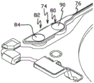
图15A至图15B示出了根据本发明的实施例的附接结构91。在实施例 中,附接结构91被结合到支撑构件12的一个或多个对角的角部中。例如, 附接结构91可以被结合到支撑构件12的两个对角的角部中。此外,附接 结构91被构造成利用一个或多个压接部92a和92b压接诸如SMA线15a 和15b的一个或多个SMA线15。15A-15B illustrate an
如图所示,附接结构91与基底层16成一体,并且包括两个压接部92a 和92b。两个压接部92a和92b形成于基底层16中处于与主平面部分26(如 图2A和图2B所示)(例如在z方向上)隔开的高度处的突出部25上。如 图所示,每个压接部92a和92b包括第一部分94a、94b和第二部分96a、96b。第一部分94a、94b被构造成大体上沿着相应的轴线97a、97b折叠, 以将第一部分94a、94b与第二部分96a、96b压接在一起。一旦被压接在 一起,第一部分94a、94b与第二部分96a、96b将SMA线15a、15b如通 过压接部92b和SMA线15b所示地保持在位。如上面在图1A和图1B中 所示的,SMA线15的另一端联接至活动构件14。As shown, the
如图所示,第一部分94a、94b和第二部分96a、96b是整件材料。然 而,在实施例中,第一部分94a、94b和第二部分96a、96b可以是非整体 式的,并且利用粘合剂、焊缝、焊接接头和/或类似物联接在一起。As shown, the
如通过压接部92a所示,压接部92a的第一部分94a包括一组导电迹 线98,并且第二部分96a包括一组导电迹线99。在实施例中,导电迹线99 从导电迹线18a伸出。压接部92b可以具有类似的构型。如上所述,导电 迹线18a和18b可以分别联接至单独的端子垫30a和30b。此外,电介质 100的一个或多个层位于导电迹线98、99和基底层16之间,以使迹线98、99与基底层16电绝缘。在实施例中,位于导电迹线98和99之间的电介质 100可以是单件电介质;或者可替代地,位于导电迹线98和99之间的电介 质100可以具有分别沿着轴线97a和97b的间断(如图15B的压接部92a 所示),以帮助沿着轴线97a和97b折叠第一部分94a和94b。此外,在实 施例中,如图15B所示,迹线98和迹线99的长度可以交错。使迹线98 和迹线99的长度交错可以减小SMA线15接触第一部分98和第二部分99 之间的弯曲的可能性,这种接触可能使SMA线15短路至基底层16。在实 施例中,迹线98和迹线99可以由铜、铜合金或其它导体形成。在实施例 中,可以在迹线98和迹线99的全部或部分上施加绝缘覆盖层。可以在迹 线98和迹线99的部分上镀覆或以其它方式施加诸如金(Au)和/或镍(Ni) 的耐腐蚀金属,以便提供耐腐蚀性。可以将聚酰亚胺或其它绝缘材料用作 电介质100。The
由于电介质100的层将迹线98和迹线99与基底层16隔离,并且由于 导电迹线18a和导电迹线18b可以分别联接至单独的端子垫30a和端子垫 30b,所以每个SMA线15a和15b可以被独立地致动以移动和控制活动构 件14。由于这种构型,因此基底层16可以是单件式。相比之下,传统的实 施例可能需要被分为四块的基底层以使得每个SMA线15可被彼此独立地 致动。由于在本文所呈现的实施例中基底层16可以由单件制成,因此与传 统的实施例中使用的基底层相比,基底层16可具有更多的结构完整性和刚 性。Since the layer of
如图所示,迹线98在其间包括空间(空隙)102,并且迹线99也在其 间包括空间(空隙)104。在实施例中,空间102中的一个或多个与迹线99 中的一个或多个对准,并且空间104中的一个或多个与迹线98中的一个或 多个对准。在实施例中,迹线98和迹线99可包括例如指部、薄片、杆部 和/或类似物的细长特征。迹线98和迹线99例如以交织、交插、交错和/ 或类似的关系相对彼此偏移,使得在第一部分94a和第二部分96a被压接 在一起时迹线98位于空间104中并且迹线99位于空间102中。压接部92b 可包括与压接部92a类似的迹线和空间构型。如上所述,在实施例中,如 图15A所示,导电迹线99可以从导电迹线18a伸出。因此,如图16所示, 当第一部分94a、94b与第二部分96a、96b被压接在一起时,SMA线15被绕着导电迹线98和导电迹线99弯曲。As shown, traces 98 include spaces (voids) 102 therebetween, and traces 99 also include spaces (voids) 104 therebetween. In an embodiment, one or more of
图16示出了压接部92b的横截面图。在实施例中,当压接部92a的第 一部分94a和第二部分96a被压接在一起时,压接部92a可以具有类似的 构型。如图所示,当第一部分94b和第二部分96b被压接在一起时,导电 迹线98和导电迹线99提供垂直于SMA线15的纵向轴线的力。因此,迹 线98和迹线90使SMA线15变形并进入到空间102和空间104中。由于 这种构型,相比于如果SMA线15被两件平坦的材料保持在位,SMA线 15可以被压接部92b更牢固地保持在位。FIG. 16 shows a cross-sectional view of the crimping
在实施例中,导电迹线98和导电迹线99的宽度106、空间102和空间 104的宽度108、以及导电迹线98与导电迹线99之间的距离110可以取决 于SMA线15的挠性而改变。例如,如果第一SMA线15比第二SMA线 15更硬并且正在使用第一SMA线15,则空间104的宽度108以及导电迹 线98和导电迹线99之间的距离110可以比如果正在使用第二SMA线15 时更大。作为另一示例,如果正在使用第一SMA线15,则迹线98的宽度 106可以比如果正在使用第二SMA线15时更小,以便在SMA线15上提 供更局部的垂直力。In an embodiment, the
在实施例中,在一个或多个SMA线15被压接在压接部92a和压接部 92b之间后,可能需要从SMA线15的线轴切断SMA线15。附加地或可 选择地,可能需要移除延伸超出压接部92a和压接部92b的边缘的多余SMA 线15。在实施例中,可以使用按压位于基底层16和/或使迹线18与基底层 16分开的电介质100中的线的工具来对SMA线15进行剪切。然而,在一 些情况下,这可能导致SMA线15接触并短接至基底层16。因此,在实施 例中,可以将垫放置在电介质的顶部、SMA线15下方。In an embodiment, after one or
图17和图18示出了根据本发明的实施例的分别包括示例性的切割垫 112a和112b的附接构件。如上所述,切割垫112a和112b可用于从线轴切 断SMA线15和/或切断不需要的任何多余的SMA线15。这可以减小SMA 线15短接至基底层16的可能性。在实施例中,垫112a和垫112b可分别 位于凸缘25上邻近压接部92a的边缘113a和压接部92b的边缘113b的位置。垫112a和垫112b可以定位在压接部92a和压接部92b的外部以使得 当压接部92a和压接部92b被压接时垫112a和垫112b被暴露出来、和/或 垫112a和垫112b可包括延伸超出压接部92a的边缘113a和压接部92b的 边缘113b的部分以使得当压接部92a和压接部92b被压接时垫112a和垫 112b被暴露出来。17 and 18 illustrate attachment members including
在实施例中,垫112a和垫112b可以由金属制成。例如,垫112a和垫 112b可以由与迹线18相同的诸如铜、铜合金或其它导体的材料制成。因此, 如图17所示,垫112a可以联接至迹线18。可替代地,如图18所示,垫 112b可以不与迹线18联接。在其它实施例中,垫112a和垫112b可以由非 金属材料制成和/或包括覆于该垫上的覆盖层。In an embodiment, the
图19示出了根据本发明的实施例的能够结合到活动构件14中的附接 结构114。如图所示,附接结构114包括两个压接部115。两个压接部115 与板60成一体,并且每个压接部115包括第一部分116和第二部分118。 第一部分116被构造成大体上沿着相应的轴线120a和轴线120b折叠,以 便使第一部分116和第二部分118被压接在一起。当第一部分116和第二 部分118被压接在一起时,它们将SMA线15保持在位。如上面在图1A 和图1B中示出的,SMA线15的另一端联接至支撑构件12。Figure 19 shows an
第一部分116和第二部分118包括设置在板60上的细长特征(部) 122a-122d。此外,细长特征122a-122d在其间包括空间124a-124d。在实施 例中,空间124a-124d中的一个或多个与细长特征122a-122d中的一个或多 个对准。在实施例中,细长特征122a-122d可以是例如指部、薄片、杆部 和/或类似物。细长特征122a及122b和细长特征122c及122d例如以交织、 交插、交错和/或类似的关系相对彼此偏移,使得当第一部分116和第二部 分118被压接在一起时细长特征122a和122b位于空间124c和124d中、 并且细长特征122c和122d位于空间124a和124b中。因此,当第一部分 116与第二部分118被压接在一起时,细长特征122a-122d提供垂直于SMA 线15的纵向轴线的力。因此,细长特征122a-122d使SMA线15变形并进 入到空间124a-124d中。由于这种构型,相比于如果SMA线15被两件平 坦的材料保持在位,SMA线15可以被压接部115更牢固地保持在位。The
在实施例中,细长特征122a-122d可以由导电材料或电介质制成。例 如,细长特征122a-122d可以由铜、铜合金或其它导体、或者聚酰亚胺或 其它绝缘材料形成。In an embodiment, the
在实施例中,导电层126可以设置在细长特征122上。然而,由于细 长特征122的部分包括空间124a-124d,因此当细长特征122a-122d由电介 质制成时,SMA线15可以经由导电层126电联接至板60。类似于上面讨 论的空间104的宽度108以及导电迹线98和导电迹线99之间的距离110, 细长特征122a-122d的宽度和空间124a-124d的宽度可以取决于SMA的挠 性而改变。在实施例中,导电层126可以由铜、铜合金或其它导体形成。 在实施例中,可以在导电层126的全部或部分上施加绝缘覆盖层。可以在 导电层126的部分上镀覆或以其它方式施加诸如金(Au)和/或镍(Ni)的 耐腐蚀金属,以便提供耐腐蚀性。可以将聚酰亚胺或其它绝缘材料用作细 长特征122。In an embodiment,
图20A至图20C示出可以结合到上述附接结构中的一个或多个中的压 接部128的另一实施例。在实施例中,多个压接部128可以结合到活动构 件14的一个或多个对角的角部中的每个中。例如,如图21所示,四个压 接部128能够以每个对角的角部两个压接部128来结合到活动构件14的两 个对角的角部。Figures 20A-20C illustrate another embodiment of a
如图所示,压接部128与板60成一体,并且包括第一部分130和第二 部分132。第一部分130被构造成大体上沿着轴线134折叠,以便将第一部 分130和第二部分132压接在一起。如图20B和图20C所示,当第一部分 130和第二部分132被压接在一起时,它们将SMA线15保持在位。如上 面在图1A和图1B示出的,SMA线15的另一端联接至支撑构件12。As shown, the
在该实施例中,压接部128包括凹部136。如图20A所示,可以从板 60的第二部分132蚀刻出凹部136。此外,第一部分130可包括多个细长 构件138、140,它们在其间包括空间。虽然示出了三个细长构件138、140, 但是可替代的实施例可包括更多个或更少个细长构件138、140。当第一部 分130和第二部分132被压接在一起时,细长构件中的至少一个、例如细 长构件140延伸到凹部136中。虽然仅一个细长构件140被示出延伸到凹 部136中,但是在其它实施例中其它细长构件可以延伸到相应的凹部或同 一凹部中。此外,如图20B和图20C所示,当第一部分130和第二部分132 被压接在一起时,细长构件138可接触第二部分132的顶部。在实施例中, 凹部136的边缘和细长构件138及140的边缘可以是倒圆的,使得当SMA 线15被细长构件140压入凹部136中时,SMA线15不太可能受损伤。In this embodiment, the
由于细长构件140延伸到凹部136中,因此当第一部分130和第二部 分132被压接在一起时,细长构件140提供垂直于SMA线15的纵向轴线 的力。因此,细长构件140使SMA线15变形并进入到凹部136中。由于 这种构型,相比于如果SMA线15被两件平坦的材料保持在位,SMA线 15可以被压接部128更牢固地保持在位。Because the
在实施例中,细长构件140可包括在细长构件140的底侧143(未示出) 和/或顶侧144(如图20C所示)上的附加的材料层142,使得细长构件140 延伸到凹部136中和/或使得细长构件140比细长构件140在其它方式中更 进一步延伸到凹部136中。因此,可以使用平坦的压接工具将第一部分130 和第二部分132压接在一起。In embodiments, the
图21示出了根据本发明的实施例的活动构件14的基底层60。如图所 示,基底层60可以是大体上平坦的,并且包括附接结构146。在实施例中, 板60的两个对角的角部148可包括两个附接结构146。每个附接结构146 可包括例如分别如图19及图20A至图20C所示的压接部115和压接部128 的压接部。附加地或可选择地,板60的附接结构146可包括例如多个凹部 的阵列、一个或多个蚀刻图案和/或局部蚀刻图案的阵列的一个或多个凹 部。相比于如果SMA线15被两件平坦的材料保持在位,被包括在附接结 构146中的一个或多个凹部可以更牢固地保持SMA线15。可以使用以上 关于图8至图14描述的蚀刻方法中的一种或多种来形成蚀刻图案。在实施 例中,可以在蚀刻图案上设置介电层和导电层。在制作蚀刻图案后,局部 蚀刻图案的角部可以是倒圆的,以减小损伤SMA线15的可能性。FIG. 21 shows the
图22A至图24B示出了可以蚀刻到附接结构146中的局部蚀刻图案的 实施例。在如图22A至图24B所示的实施例中的每个中,可以通过局部蚀 刻图案使被紧固至附接结构146的SMA线15变形。因此,相比于如果SMA 线15被两件平坦的材料保持在位,SMA线15可以被附接结构146更牢固 地保持在位。22A-24B illustrate an embodiment of a partial etch pattern that may be etched into the
作为示例,如图22A至图22B所示,局部蚀刻图案150可以是交错的 线性凹部。在实施例中,当被包括在附接结构146中的压接部被压接时, 局部蚀刻图案150可以例如以交织、交插、交错和/或类似的关系相对彼此 偏移。作为另一示例,如图23A至图23B所示,局部蚀刻图案152可以是 凹部的阵列。作为又一示例,如图24A至图24B所示,局部蚀刻图案154可以是平行的锯齿形(zig-zag)。As an example, as shown in Figures 22A-22B, the
图25A至图25C示出了根据本发明的实施例的能够被结合到活动构件 14中的另一附接结构160。在实施例中,下面所讨论的附接结构160的特 征可以被结合到本文所讨论的其它附接结构中。如图所示,附接结构160 包括两个压接部162。压接部162与板60成一体,并且包括第一部分164 和第二部分166。第一部分164被构造成大体上沿着轴线168折叠,以便将 第一部分164和第二部分166压接在一起。当第一部分164和第二部分166 被压接在一起时,它们能够将SMA线15保持在位。如上面在图1A和图 1B中所示的,SMA线15的另一端联接至支撑构件12。Figures 25A-25C illustrate another
如图所示,第一部分164包括凹部170,并且第二部分166包括细长构 件172。当第一部分164和第二部分166被压接在一起时,细长构件172 延伸到凹部170中。当第一部分164和第二部分166被压接在一起时,细 长构件172使SMA线15变形并进入到凹部170中。由于这种构型,相比 于如果SMA线15被两件平坦的材料保持在位,SMA线15可以被压接部 162更牢固地保持在位。在实施例中,如图25B和图25C所示,边缘176 可包括延伸超出边缘174的部分177,使得当第一部分164和第二部分166 被压接在一起时,第一部分164配合到第二部分166。As shown, the
此外,第一部分164包括边缘174,并且第二部分166包括相对于边缘 174偏移的边缘176。当第一部分164和第二部分166被压接在一起时,边 缘174和边缘176被构造以形成能够切断SMA线15的切削刃。图25B示 出了两个压接部162都闭合的附接结构160,图25C示出了在边缘174和 边缘176切断SMA线15的端部部分后的附接结构160。Additionally, the
图26A至图26B示出了根据本发明的实施例的压接部178的另一实施 例。类似于上述压接部,压接部178可以被结合到活动构件14和/或上述 的附接结构中。压接部178与板60成一体,并且包括被构造以折叠在一起 的第一部分180和第二部分182。如图26B所示,当第一部分180和第二 部分182被折叠在一起时,它们能够将SMA线15压接在位。26A-26B illustrate another embodiment of a
如图所示,压接部178包括蚀刻出的凹部184。凹部184大体上位于压 接部178在第一部分180和第二部分182被压接在一起时的弯曲部位186。 而且,凹部184位于该弯曲部位186的外部部分上。凹部184可以降低弯 曲部位186上的应力,这可以减小板60在第一部分180和第二部分182被 压接在一起时开裂的可能性。在实施例中,当板60由更厚的金属制成时和 /或当板60由塑性(延性)较低和/或延展性较低的金属制成时,这可能是 有利的。在实施例中,可以通过诸如上面关于图8至图14描述的蚀刻方法 的蚀刻形成凹部184。As shown, the
在实施例中,与蚀刻出的凹部184类似的蚀刻出的凹部可以被包括在 支撑构件12中。即,该蚀刻出的凹部例如可以大体上位于压接部92a和压 接部92b在第一部分94a及94b和第二部分96a及96b被压接在一起时的 弯曲部位。In an embodiment, an etched recess similar to the etched
图27A至图27C示出了根据本发明的实施例的压接部187的另一实施 例。类似于上述压接部,压接部187可以被结合到支撑构件12、活动构件 14和/或上面分别关于支撑构件12和活动构件14所示的附接结构中。压接 部187与板60成一体,并且包括被构造以折叠在一起的第一部分188和第 二部分190。如图所示,当第一部分164和第二部分166被折叠在一起时, 它们能够将SMA线15压接在位。27A to 27C illustrate another embodiment of a
压接部187包括从压接部187的至少一侧延伸并支撑SMA线15和/ 或在SMA线15上提供压接力的应变消除构件192。如图所示,应变消除 构件192从压接部187的两侧延伸;然而,在其它实施例中,应变消除构 件192仅从压接部187的一侧延伸。The
在传统的实施例中,当悬置组件10受到应力时,由于SMA离开压接 部的侧面的区域是固有的高应力区域,SMA线15可能在邻近SMA线离开 压接部的侧面的区域受损伤和/或断开。在悬置组件10受到应力时,由于 应变消除构件192可以与SMA线15一起弯曲,因此应变消除构件192减 小了SMA线15上的应力,从而增加SMA线15的弯曲半径。即,替代例 如具有宽度x的可能以角度θ弯曲的一段SMA线15,应变消除构件192 可以使以角度θ弯曲的段的宽度增加至例如2*x、3*x、4*x等。这使得SMA 线15上的应力分布在SMA线15的较大部分上。在实施例中,应变消除构 件192从压接部187的侧面伸出的距离可以根据取决于SMA线15所使用 的材料的类型、刚度和/或厚度而改变。In conventional embodiments, when the
在实施例中,应变消除构件192可以由金属制成。例如,应变消除构 件192可以由与迹线18相同的诸如铜、铜合金或其它导体的材料制成。因 此,应变消除构件192可以联接至迹线18。在实施例中,可以在应变消除 层192的全部或部分上施加绝缘覆盖层。可以在应变消除层192的部分上 镀覆或以其它方式施加诸如金(Au)和/或镍(Ni)的耐腐蚀金属,以便提 供耐腐蚀性。附加地或可替代地,应变消除构件192可以由电介质制成。 例如,应变消除构件192可以由与电介质78相同的材料制成。电介质的示 例可包括聚酰亚胺或其它绝缘材料。附加地或可替代地,如图27B和图27C 所示,应变消除构件192可包括在应变消除的内部上的金属垫194。在实施 例中,金属垫194可以帮助夹紧SMA线15并减小SMA线15从应变消除 构件192滑出的可能性。In an embodiment, the
图28A至图28B示出了根据本发明的实施例的压接部196的另一实施 例。类似于上述压接部,压接部196可以被结合到支撑构件12、活动构件 14和/或上面分别关于支撑构件12和活动构件14示出的附接结构。压接部 196包括两个部分:第一部分198和第二部分200,它们被构造以折叠在一 起。当第一部分198和第二部分200被折叠在一起时,它们能够将SMA线 15压接在位。当支撑构件10受到应力时,可以将上述实施例中的一个或多 个结合到压接部196中以增大压接部196的保持强度和/或减小SMA线15 上的应变。28A-28B illustrate another embodiment of a
第二部分200可以与板60成一体。第一部分198不与第二部分200成 一体,但是可以利用粘合剂、焊缝、焊接接头和/或类似物联接至第二部分 200。第一部分198和第二部分200可以在SMA线15的任一侧上联接在一 起。即,在实施例中,第一部分198和第二部分200可以在压接196的内 侧202或该压接部的外侧204上联接。The
图29示出了根据本发明的实施例的活动构件14的基底层60。如图所 示,基底层60可以是大体上平坦的,并且包括附接结构206。在实施例中, 板60的两个对角的角部208可包括两个附接结构206。每个附接结构206 可包括例如图28A至图28B所示的压接部196的压接部210。例如,被包 括在附接结构206中的压接部210可包括不与第二部分214成一体但是利 用粘合剂、焊缝、焊接接头和/或类似物联接至第二部分214的第一部分212。 附加地或可替代地,板60的附接结构206可包括蚀刻图案。相比于如果 SMA线15被两件平坦的材料保持在位,被包括在附接结构206中的蚀刻 图案可以更牢固地保持SMA线15。可以使用上面关于图8至图14描述的 蚀刻方法中的一种或多种来形成蚀刻图案。在实施例中,介电层和导电层 可以设置在蚀刻图案上。在制作蚀刻图案后,局部蚀刻图案的角部可以是 倒圆的,以减小损伤SMA线15的可能性。Figure 29 shows the
虽然已经参考优选的实施例描述了本发明的实施例,但是本领域技术 人员将认识到,在不脱离本发明的精神和范围的情况下,可以在形式和细 节上进行改变。例如,尽管所示的实施例包括位于挠曲臂与支撑构件(即, 在迹线的顶侧上)相反的侧面上的迹线,但是其它实施例能够可替代地或 额外地包括在挠曲臂面向活动构件(即,在迹线的底侧上)的侧面上的迹 线。Although embodiments of the present invention have been described with reference to preferred embodiments, workers skilled in the art will recognize that changes may be made in form and detail without departing from the spirit and scope of the invention. For example, while the illustrated embodiment includes traces on the opposite side of the flexure arm from the support member (ie, on the top side of the traces), other embodiments can alternatively or additionally include traces on the flexure arm The arm faces the trace on the side of the movable member (ie, on the bottom side of the trace).
Claims (24)
Priority Applications (1)
| Application Number | Priority Date | Filing Date | Title |
|---|---|---|---|
| CN202010257836.5A CN111562681B (en) | 2015-03-06 | 2016-03-07 | Shape memory alloy wire attachment structures for suspended components |
Applications Claiming Priority (5)
| Application Number | Priority Date | Filing Date | Title |
|---|---|---|---|
| US201562129562P | 2015-03-06 | 2015-03-06 | |
| US62/129,562 | 2015-03-06 | ||
| CN201680025323.3A CN107532574B (en) | 2015-03-06 | 2016-03-07 | Shape memory alloy wire attachment structure for suspension assembly |
| CN202010257836.5A CN111562681B (en) | 2015-03-06 | 2016-03-07 | Shape memory alloy wire attachment structures for suspended components |
| PCT/US2016/021230 WO2016144895A1 (en) | 2015-03-06 | 2016-03-07 | Shape memory alloy wire attachment structures for a suspension assembly |
Related Parent Applications (1)
| Application Number | Title | Priority Date | Filing Date |
|---|---|---|---|
| CN201680025323.3A Division CN107532574B (en) | 2015-03-06 | 2016-03-07 | Shape memory alloy wire attachment structure for suspension assembly |
Publications (2)
| Publication Number | Publication Date |
|---|---|
| CN111562681A true CN111562681A (en) | 2020-08-21 |
| CN111562681B CN111562681B (en) | 2024-03-15 |
Family
ID=56849866
Family Applications (2)
| Application Number | Title | Priority Date | Filing Date |
|---|---|---|---|
| CN201680025323.3A Active CN107532574B (en) | 2015-03-06 | 2016-03-07 | Shape memory alloy wire attachment structure for suspension assembly |
| CN202010257836.5A Active CN111562681B (en) | 2015-03-06 | 2016-03-07 | Shape memory alloy wire attachment structures for suspended components |
Family Applications Before (1)
| Application Number | Title | Priority Date | Filing Date |
|---|---|---|---|
| CN201680025323.3A Active CN107532574B (en) | 2015-03-06 | 2016-03-07 | Shape memory alloy wire attachment structure for suspension assembly |
Country Status (6)
| Country | Link |
|---|---|
| US (3) | US9454016B1 (en) |
| EP (1) | EP3265678B1 (en) |
| JP (2) | JP7185400B2 (en) |
| KR (1) | KR102619009B1 (en) |
| CN (2) | CN107532574B (en) |
| WO (1) | WO2016144895A1 (en) |
Cited By (2)
| Publication number | Priority date | Publication date | Assignee | Title |
|---|---|---|---|---|
| CN114200627A (en) * | 2020-08-26 | 2022-03-18 | 阿尔卑斯阿尔派株式会社 | Lens driver and camera module |
| CN115943257A (en) * | 2019-12-01 | 2023-04-07 | 剑桥机电有限公司 | actuator assembly |
Families Citing this family (37)
| Publication number | Priority date | Publication date | Assignee | Title |
|---|---|---|---|---|
| GB201412848D0 (en) | 2014-07-18 | 2014-09-03 | Cambridge Mechatronics Ltd | Suspension system for a camera lens element |
| US9366879B1 (en) | 2014-12-02 | 2016-06-14 | Hutchinson Technology Incorporated | Camera lens suspension with polymer bearings |
| US9454016B1 (en) | 2015-03-06 | 2016-09-27 | Hutchinson Technology Incorporated | Camera lens suspension with integrated electrical leads |
| US10670878B2 (en) | 2016-05-19 | 2020-06-02 | Hutchinson Technology Incorporated | Camera lens suspensions |
| WO2017214583A1 (en) | 2016-06-09 | 2017-12-14 | Hutchinson Technology Incorporated | Shape memory alloy wire attachment structures with adhesive for a suspension assembly |
| JP2020515881A (en) | 2016-12-16 | 2020-05-28 | ハッチンソン テクノロジー インコーポレイテッドHutchinson Technology Incorporated | Sensor shift structure in optical image stabilization suspension |
| EP3555470A4 (en) | 2016-12-16 | 2020-12-09 | Hutchinson Technology Incorporated | SENSOR DISPLACEMENT STRUCTURES IN SUSPENSIONS FOR THE STABILIZATION OF OPTICAL IMAGES |
| US12147059B2 (en) | 2016-12-16 | 2024-11-19 | Hutchinson Technology Incorporated | Sensor shift structures in optical image stabilization suspensions |
| KR102400118B1 (en) * | 2017-08-14 | 2022-05-19 | 엘지이노텍 주식회사 | A lens moving unit, and camera module and optical instrument including the same |
| CN110662999B (en) | 2017-04-06 | 2021-12-24 | Lg伊诺特有限公司 | Lens driving unit, and image pickup device module and optical device including the same |
| GB201707542D0 (en) * | 2017-05-11 | 2017-06-28 | Cambridge Mechatronics Ltd | Compact SMA shutter actuator |
| WO2018211047A1 (en) * | 2017-05-17 | 2018-11-22 | Cambridge Mechatronics Limited | Electrical connections for sma actuators |
| CN109212710B (en) | 2017-06-29 | 2021-01-15 | 台湾东电化股份有限公司 | Lens driving system and circuit module thereof |
| KR102148513B1 (en) | 2017-09-28 | 2020-08-26 | 주식회사 엘지화학 | A carbon -surfur complex, manufacturing method thereof and lithium secondary battery comprising the same |
| US10634929B2 (en) * | 2017-10-19 | 2020-04-28 | Tdk Taiwan Corp. | Optical driving mechanism |
| CN108247309B (en) * | 2017-12-20 | 2020-05-22 | 东莞市亚登电子有限公司 | Memory alloy wire installation method for miniature optical camera module |
| CN108111724B (en) * | 2017-12-20 | 2020-05-19 | 东莞市亚登电子有限公司 | Memory alloy wire implantation method for miniature optical camera module |
| GB2583854B (en) | 2018-01-22 | 2023-02-01 | Cambridge Mechatronics Ltd | Shape memory alloy actuation apparatus |
| US11019266B1 (en) | 2018-08-31 | 2021-05-25 | Apple Inc. | Blunting optical suspension springs for particle reduction |
| JP2020056379A (en) * | 2018-10-03 | 2020-04-09 | フォスター電機株式会社 | Actuator |
| US11226466B2 (en) * | 2019-02-01 | 2022-01-18 | Tdk Taiwan Corp. | Optical element driving mechanism |
| GB201907018D0 (en) * | 2019-05-17 | 2019-07-03 | Cambridge Mechatronics Ltd | Actuator assembly |
| WO2020243861A1 (en) * | 2019-06-01 | 2020-12-10 | 瑞声光学解决方案私人有限公司 | Automatic focusing lens assembly |
| US11503211B2 (en) | 2019-08-16 | 2022-11-15 | Hutchinson Technology Incorporated | Stabilization suspensions and methods of manufacture |
| GB2587906A (en) * | 2019-08-16 | 2021-04-14 | Hutchinson Technology | Stabilization suspensions and methods of manufacture |
| CN110703404A (en) * | 2019-09-11 | 2020-01-17 | 瑞声科技(新加坡)有限公司 | lens module |
| CN112698462B (en) | 2019-10-18 | 2024-12-27 | 新思考电机有限公司 | Optical component driving device, camera device, and electronic device |
| CN112752013B (en) * | 2019-10-30 | 2025-02-11 | 晋城三赢精密电子有限公司 | Anti-shake device, camera module and electronic device |
| CN110908066B (en) * | 2019-12-12 | 2024-11-29 | 河南皓泽电子股份有限公司昆山分公司 | Multi-axis optical anti-shake and focusing device, camera module and electronic equipment |
| CN212211175U (en) * | 2020-06-23 | 2020-12-22 | 新思考电机有限公司 | OIS motor drive structure, OIS motor, camera device |
| US11582389B2 (en) * | 2020-08-11 | 2023-02-14 | Apple Inc. | Electrical traces in suspension assemblies |
| CN216595833U (en) | 2020-09-02 | 2022-05-24 | 哈钦森技术股份有限公司 | Guided autofocus assembly |
| US11194115B1 (en) | 2020-09-02 | 2021-12-07 | Hutchinson Technology Incorporated | Guided autofocus assembly |
| GB2602627B (en) * | 2020-12-31 | 2023-06-07 | Cambridge Mechatronics Ltd | Actuator assemblies |
| GB2607269A (en) * | 2021-04-14 | 2022-12-07 | Cambridge Mechatronics Ltd | SMA actuator assembly |
| CN113109916B (en) * | 2021-05-10 | 2024-12-20 | 中山联合光电科技股份有限公司 | Positioning structure and optical zoom lens |
| US12498537B1 (en) * | 2022-09-14 | 2025-12-16 | Apple Inc. | Flexure module component configurations for camera with moveable image sensor |
Citations (4)
| Publication number | Priority date | Publication date | Assignee | Title |
|---|---|---|---|---|
| US5687479A (en) * | 1994-04-15 | 1997-11-18 | Hutchinson Technology Incorporated | Electrical trace interconnect assembly |
| US20100119863A1 (en) * | 2006-06-22 | 2010-05-13 | Robert Bogursky | Apparatus and methods for filament crimping and manufacturing |
| US20110179786A1 (en) * | 2008-07-30 | 2011-07-28 | Cambridge Mechatronics Limited | Shape memory alloy actuation apparatus |
| WO2014083318A1 (en) * | 2012-11-27 | 2014-06-05 | Cambridge Mechatronics Limited | Suspension system for a camera lens element |
Family Cites Families (111)
| Publication number | Priority date | Publication date | Assignee | Title |
|---|---|---|---|---|
| CH457131A (en) | 1967-09-06 | 1968-05-31 | Koch Carl | Photographic focusing screen camera |
| US3776447A (en) | 1969-06-30 | 1973-12-04 | Texas Instruments Inc | Automatic semiconductor bonding machine |
| US3734386A (en) | 1971-06-30 | 1973-05-22 | Ibm | Wiring apparatus with wire path forming means |
| US4140265A (en) | 1975-06-26 | 1979-02-20 | Kollmorgen Technologies Corporation | Method and apparatus for positioning the end of a conductive filament at a predetermined and repeatable geometric location for coupling to a predetermined terminal area of an element |
| JPS5698900A (en) | 1980-01-07 | 1981-08-08 | Hitachi Ltd | Device for automatically wiring printed circuit board |
| JPS57201739U (en) | 1981-06-19 | 1982-12-22 | ||
| JPS59104565U (en) | 1982-12-29 | 1984-07-13 | 日本メクトロン株式会社 | flexible circuit board |
| EP0203597B1 (en) | 1985-05-31 | 1990-07-11 | Emhart Industries, Inc. | Bonding head |
| US5743654A (en) | 1987-05-29 | 1998-04-28 | Kmc, Inc. | Hydrostatic and active control movable pad bearing |
| JPS6473754A (en) | 1987-09-16 | 1989-03-20 | Nec Corp | Manufacture of lead frame for semiconductor device |
| JPH01186577A (en) | 1988-01-13 | 1989-07-26 | Shin Nippon Koki Kk | Connector connection tool |
| US4984581A (en) | 1988-10-12 | 1991-01-15 | Flexmedics Corporation | Flexible guide having two-way shape memory alloy |
| JPH0358464A (en) | 1989-07-26 | 1991-03-13 | Nec Corp | Semiconductor device |
| JPH05283146A (en) | 1992-03-31 | 1993-10-29 | Toshiba Lighting & Technol Corp | Thick film resistance heating element |
| US5269810A (en) | 1992-06-19 | 1993-12-14 | W. L. Gore & Associates, Inc. | Patch electrode |
| JP2959322B2 (en) | 1993-03-09 | 1999-10-06 | 住友電装株式会社 | Harness electric wire manufacturing apparatus and manufacturing method |
| JPH06275325A (en) | 1993-03-24 | 1994-09-30 | Mitsubishi Electric Home Appliance Co Ltd | Connecting structure for conducting wire |
| US5667884A (en) | 1993-04-12 | 1997-09-16 | Bolger; Justin C. | Area bonding conductive adhesive preforms |
| JPH07259725A (en) | 1994-03-17 | 1995-10-09 | Olympus Optical Co Ltd | Flexible tube curing device |
| DE19549174A1 (en) * | 1995-10-28 | 1997-07-03 | Bosch Gmbh Robert | Contact element with crimp section |
| US5831820A (en) | 1996-12-30 | 1998-11-03 | Huang; James | Peripheral docking module using a shape memory alloy actuator wire |
| US6149742A (en) | 1998-05-26 | 2000-11-21 | Lockheed Martin Corporation | Process for conditioning shape memory alloys |
| JP3488100B2 (en) | 1998-10-13 | 2004-01-19 | 矢崎総業株式会社 | Automatic cutting and crimping equipment |
| MXPA02001452A (en) | 1999-08-12 | 2003-07-21 | Manomuscle Inc | MEMORY ALLOY ACTUATORS OF FORM AND CONTROL METHODS. |
| US6639411B1 (en) | 2000-09-05 | 2003-10-28 | Hutchinson Technology Incorporated | Microactuated suspension motor failure detection system |
| JP2002130114A (en) | 2000-10-20 | 2002-05-09 | Toshiba Corp | Actuator device |
| EP1364125A1 (en) | 2001-01-17 | 2003-11-26 | M 2 Medical A/S | Shape memory alloy actuator |
| JP4406707B2 (en) | 2001-06-06 | 2010-02-03 | ソニー株式会社 | Two-axis device for optical disk device |
| JP4278364B2 (en) | 2002-11-08 | 2009-06-10 | パイオニア株式会社 | Actuator for pickup device |
| US6916115B1 (en) | 2003-03-04 | 2005-07-12 | University Of Kentucky Research Foundation | System and device for characterizing shape memory alloy wires |
| EP1711860A1 (en) | 2004-02-06 | 2006-10-18 | Koninklijke Philips Electronics N.V. | Camera arrangement, mobile phone comprising a camera arrangement, method of manufacturing a camera arrangement |
| JP2005227365A (en) | 2004-02-10 | 2005-08-25 | Sony Corp | Manufacturing method of optical components |
| US7384531B1 (en) | 2004-02-19 | 2008-06-10 | Hutchinson Technology Incorporated | Plated ground features for integrated lead suspensions |
| JP2007537562A (en) | 2004-05-14 | 2007-12-20 | ハッチンソン テクノロジー インコーポレーティッド | Method for producing noble metal conductive lead for suspension assembly |
| US7679647B2 (en) | 2004-07-21 | 2010-03-16 | Hewlett-Packard Development Company, L.P. | Flexible suspension for image stabilization |
| KR100725341B1 (en) | 2004-08-12 | 2007-06-07 | 가부시키가이샤 무라타 세이사쿠쇼 | Piezoelectric Acoustic Transducer |
| JP4186907B2 (en) | 2004-10-14 | 2008-11-26 | ソニー株式会社 | Electronics |
| JP2007092556A (en) | 2005-09-27 | 2007-04-12 | Konica Minolta Opto Inc | Drive device and its manufacturing method |
| US7777782B2 (en) | 2005-11-04 | 2010-08-17 | Nokia Corporation | Stabilization of an image produced by optics |
| JP4737756B2 (en) | 2006-02-27 | 2011-08-03 | Necトーキン株式会社 | Solid electrolytic capacitor |
| GB0606425D0 (en) | 2006-03-30 | 2006-05-10 | 1 Ltd | Camera lens actuation apparatus |
| ATE523806T1 (en) | 2006-03-30 | 2011-09-15 | Cambridge Mechatronics Ltd | CAMERA LENS ACTUATOR |
| US8175449B2 (en) | 2006-05-30 | 2012-05-08 | Konica Minolta Opto, Inc. | Driving device, driving mechanism, and image sensing apparatus |
| US7832082B1 (en) | 2006-10-10 | 2010-11-16 | Hutchinson Technology Incorporated | Method for manufacturing an integrated lead suspension component |
| US7929252B1 (en) | 2006-10-10 | 2011-04-19 | Hutchinson Technology Incorporated | Multi-layer ground plane structures for integrated lead suspensions |
| JP4816397B2 (en) | 2006-10-12 | 2011-11-16 | 住友電気工業株式会社 | Photoelectric conversion module |
| AU2008210504B2 (en) | 2007-01-29 | 2012-07-26 | Spinal Modulation, Inc. | Sutureless lead retention features |
| GB0702676D0 (en) * | 2007-02-12 | 2007-03-21 | 1 Ltd | Method of driving a shape memory alloy actuator |
| GB2457860B (en) | 2007-02-12 | 2010-06-30 | Cambridge Mechatronics Ltd | Shape memory alloy actuation apparatus |
| GB0702835D0 (en) | 2007-02-14 | 2007-03-28 | Johnson Electric Sa | Lens module |
| JP2008233526A (en) | 2007-03-20 | 2008-10-02 | Tamron Co Ltd | Actuator for preventing image shake and camera equipped therewith |
| US7974025B2 (en) | 2007-04-23 | 2011-07-05 | Cambridge Mechatronics Limited | Shape memory alloy actuation apparatus |
| EP2140138B1 (en) | 2007-04-23 | 2012-04-11 | Cambridge Mechatronics Limited | Shape memory alloy actuation apparatus |
| JP5194622B2 (en) | 2007-08-02 | 2013-05-08 | コニカミノルタアドバンストレイヤー株式会社 | Drive mechanism, drive device, and lens drive device |
| CN101408655B (en) | 2007-10-11 | 2011-07-27 | 鸿富锦精密工业(深圳)有限公司 | Lens module |
| JP5101984B2 (en) | 2007-10-23 | 2012-12-19 | セイコーインスツル株式会社 | Drive module |
| JP4355742B2 (en) | 2007-10-31 | 2009-11-04 | 三菱電機エンジニアリング株式会社 | Short-circuit plate |
| KR20090081855A (en) | 2008-01-25 | 2009-07-29 | 이-핀 옵티칼 인더스트리 컴퍼니 리미티드 | Lens Displacement Mechanism Using Shape Memory Alloy |
| US8388773B2 (en) | 2008-03-07 | 2013-03-05 | GM Global Technology Operations LLC | Apparatus for and method of conditioning shape memory alloy wire |
| US8169746B1 (en) | 2008-04-08 | 2012-05-01 | Hutchinson Technology Incorporated | Integrated lead suspension with multiple trace configurations |
| US20110107758A1 (en) | 2008-07-11 | 2011-05-12 | Seiko Instruments Inc. | Drive module, method of assembling the same, and electronic apparatus |
| EP2326984A2 (en) | 2008-09-12 | 2011-06-01 | Cambridge Mechatronics Limited | Optical image stabilisation comprising shape memory alloy actuators |
| JP2010128262A (en) | 2008-11-28 | 2010-06-10 | Mitsumi Electric Co Ltd | Lens drive unit and connection method |
| US8441749B2 (en) | 2009-02-09 | 2013-05-14 | Cambridge Mechatronics Limited | Shape memory alloy actuation apparatus |
| EP2394425B1 (en) | 2009-02-09 | 2017-05-31 | Cambridge Mechatronics Limited | Optical image stabilisation |
| JP2010192036A (en) | 2009-02-18 | 2010-09-02 | Funai Electric Co Ltd | Objective lens actuator |
| EP2409355B1 (en) | 2009-03-16 | 2017-09-13 | Energizer Brands, LLC | Oxygen-consuming battery with improved high rate capability |
| US8421908B2 (en) | 2009-03-25 | 2013-04-16 | Konica Minolta Opto, Inc. | Actuator, drive device, and imaging device |
| CN101876742A (en) * | 2009-04-28 | 2010-11-03 | 三美电机株式会社 | Lens driver |
| JP2011039485A (en) | 2009-07-14 | 2011-02-24 | Seiko Instruments Inc | Drive module and electronic device |
| JP4804564B2 (en) | 2009-07-14 | 2011-11-02 | キヤノン株式会社 | Optical apparatus having shake correction device |
| JP5846346B2 (en) | 2009-08-21 | 2016-01-20 | ミツミ電機株式会社 | Camera shake correction device |
| JP2011107413A (en) | 2009-11-17 | 2011-06-02 | Morioka Seiko Instruments Inc | Actuator, drive module, and electronic equipment |
| JP2011175160A (en) | 2010-02-25 | 2011-09-08 | Mitsumi Electric Co Ltd | Lens driving device |
| CN102770804B (en) | 2010-02-26 | 2015-09-23 | 剑桥机电有限公司 | SMA actuator |
| US9999763B2 (en) | 2012-06-13 | 2018-06-19 | Mainstay Medical Limited | Apparatus and methods for anchoring electrode leads adjacent to nervous tissue |
| US8885299B1 (en) | 2010-05-24 | 2014-11-11 | Hutchinson Technology Incorporated | Low resistance ground joints for dual stage actuation disk drive suspensions |
| JP2012032470A (en) | 2010-07-29 | 2012-02-16 | Sony Corp | Lens module and camera |
| KR101893229B1 (en) * | 2010-08-09 | 2018-08-29 | 캠브리지 메카트로닉스 리미티드 | Camera apparatus |
| WO2012038703A2 (en) | 2010-09-22 | 2012-03-29 | Cambridge Mechatronics Limited | Optical image stabilisation |
| GB201019532D0 (en) | 2010-11-18 | 2010-12-29 | Cambridge Mechatronics Ltd | Optical image stablisation drive |
| SG190201A1 (en) | 2010-11-22 | 2013-06-28 | Senseair Ab | Method for the wafer-level integration of shape memory alloy wires |
| US8851443B2 (en) | 2010-12-15 | 2014-10-07 | Autosplice, Inc. | Memory alloy-actuated apparatus and methods for making and using the same |
| JP5821356B2 (en) | 2011-07-15 | 2015-11-24 | ミツミ電機株式会社 | Lens drive device |
| KR101920502B1 (en) | 2011-12-29 | 2018-11-20 | 존슨 일렉트릭 에스.에이. | Bearing holder and actuator |
| JP2013178457A (en) | 2012-02-01 | 2013-09-09 | Seiko Instruments Inc | Drive module and electronic apparatus |
| US9288394B2 (en) | 2012-02-01 | 2016-03-15 | Ricoh Imaging Company, Ltd. | Stage apparatus and camera shake correction apparatus |
| WO2013121225A1 (en) | 2012-02-16 | 2013-08-22 | Cambridge Mechatronics Limited | Shape memory alloy actuation apparatus |
| KR20130098635A (en) | 2012-02-28 | 2013-09-05 | 삼성전자주식회사 | Capillary exchange system of semiconductor wire bond |
| GB201206490D0 (en) | 2012-04-12 | 2012-05-30 | Cambridge Mechatronics Ltd | Compact camera |
| JP2013238848A (en) | 2012-04-20 | 2013-11-28 | Hoya Corp | Imaging apparatus |
| US9518566B2 (en) * | 2012-05-25 | 2016-12-13 | Cambridge Mechatronics Limited | Shape memory alloy actuation apparatus |
| JP5967366B2 (en) | 2012-09-11 | 2016-08-10 | Smk株式会社 | Flat shape memory cable body and driving device using the same |
| GB201220485D0 (en) | 2012-11-14 | 2012-12-26 | Cambridge Mechatronics Ltd | Control of an SMA actuation apparatus |
| WO2014100516A1 (en) | 2012-12-20 | 2014-06-26 | Bynlac Laboratories Llc | Voice coil motor optical image stabilization |
| JP2014225378A (en) | 2013-05-16 | 2014-12-04 | 株式会社日立製作所 | Sealant for tab lead, tab lead and lithium ion secondary battery |
| KR101569345B1 (en) | 2013-07-25 | 2015-11-16 | 크루셜텍 (주) | Actuator Using Shape Memory Alloy Wire |
| US9277789B2 (en) * | 2013-09-10 | 2016-03-08 | Texas Instruments Incorporated | Current, temperature or electromagnetic field actuated fasteners |
| US10834301B2 (en) | 2013-09-12 | 2020-11-10 | Cambridge Mechatronics Limited | Insulation of SMA actuator wires in a miniature camera |
| JP2015128267A (en) | 2013-12-27 | 2015-07-09 | セイコーエプソン株式会社 | Vibrating piece, vibrator, oscillator, electronic device, sensor and moving body |
| GB201403803D0 (en) | 2014-03-04 | 2014-04-16 | Cambridge Mechatronics Ltd | SMA actuator |
| GB201412848D0 (en) | 2014-07-18 | 2014-09-03 | Cambridge Mechatronics Ltd | Suspension system for a camera lens element |
| US9366879B1 (en) | 2014-12-02 | 2016-06-14 | Hutchinson Technology Incorporated | Camera lens suspension with polymer bearings |
| US9454016B1 (en) * | 2015-03-06 | 2016-09-27 | Hutchinson Technology Incorporated | Camera lens suspension with integrated electrical leads |
| JP6447819B2 (en) | 2015-03-10 | 2019-01-09 | セイコーエプソン株式会社 | Head and liquid ejecting apparatus |
| CN107533990B (en) | 2015-04-02 | 2020-09-22 | 哈钦森技术股份有限公司 | Lead Feed and Attachment System for Camera Lens Mounts |
| GB201517202D0 (en) | 2015-09-29 | 2015-11-11 | Cambridge Mechatronics Ltd | OIS actuator improvements |
| CN116055845A (en) | 2015-10-28 | 2023-05-02 | 剑桥机电有限公司 | Camera components that provide optical image stabilization |
| US10670878B2 (en) | 2016-05-19 | 2020-06-02 | Hutchinson Technology Incorporated | Camera lens suspensions |
| WO2017214583A1 (en) | 2016-06-09 | 2017-12-14 | Hutchinson Technology Incorporated | Shape memory alloy wire attachment structures with adhesive for a suspension assembly |
| CN111405743B (en) | 2019-01-03 | 2023-09-05 | 新科实业有限公司 | Suspension assembly of optical image stabilizer |
-
2015
- 2015-09-23 US US14/863,046 patent/US9454016B1/en active Active
-
2016
- 2016-03-07 WO PCT/US2016/021230 patent/WO2016144895A1/en not_active Ceased
- 2016-03-07 CN CN201680025323.3A patent/CN107532574B/en active Active
- 2016-03-07 KR KR1020177027642A patent/KR102619009B1/en active Active
- 2016-03-07 EP EP16762309.9A patent/EP3265678B1/en active Active
- 2016-03-07 CN CN202010257836.5A patent/CN111562681B/en active Active
- 2016-03-07 US US15/063,151 patent/US11782286B2/en active Active
- 2016-03-07 JP JP2017546796A patent/JP7185400B2/en active Active
- 2016-09-26 US US15/276,115 patent/US10036897B2/en active Active
-
2021
- 2021-04-15 JP JP2021068927A patent/JP7200286B2/en active Active
Patent Citations (4)
| Publication number | Priority date | Publication date | Assignee | Title |
|---|---|---|---|---|
| US5687479A (en) * | 1994-04-15 | 1997-11-18 | Hutchinson Technology Incorporated | Electrical trace interconnect assembly |
| US20100119863A1 (en) * | 2006-06-22 | 2010-05-13 | Robert Bogursky | Apparatus and methods for filament crimping and manufacturing |
| US20110179786A1 (en) * | 2008-07-30 | 2011-07-28 | Cambridge Mechatronics Limited | Shape memory alloy actuation apparatus |
| WO2014083318A1 (en) * | 2012-11-27 | 2014-06-05 | Cambridge Mechatronics Limited | Suspension system for a camera lens element |
Cited By (3)
| Publication number | Priority date | Publication date | Assignee | Title |
|---|---|---|---|---|
| CN115943257A (en) * | 2019-12-01 | 2023-04-07 | 剑桥机电有限公司 | actuator assembly |
| CN114200627A (en) * | 2020-08-26 | 2022-03-18 | 阿尔卑斯阿尔派株式会社 | Lens driver and camera module |
| CN114200627B (en) * | 2020-08-26 | 2024-01-09 | 阿尔卑斯阿尔派株式会社 | Lens driving device and camera module |
Also Published As
| Publication number | Publication date |
|---|---|
| JP2018514679A (en) | 2018-06-07 |
| CN107532574B (en) | 2020-05-05 |
| US9454016B1 (en) | 2016-09-27 |
| JP2021193443A (en) | 2021-12-23 |
| US11782286B2 (en) | 2023-10-10 |
| CN107532574A (en) | 2018-01-02 |
| EP3265678B1 (en) | 2020-08-19 |
| US10036897B2 (en) | 2018-07-31 |
| US20170131562A1 (en) | 2017-05-11 |
| WO2016144895A1 (en) | 2016-09-15 |
| US20160258425A1 (en) | 2016-09-08 |
| CN111562681B (en) | 2024-03-15 |
| EP3265678A1 (en) | 2018-01-10 |
| KR102619009B1 (en) | 2023-12-29 |
| JP7200286B2 (en) | 2023-01-06 |
| US20160259177A1 (en) | 2016-09-08 |
| JP7185400B2 (en) | 2022-12-07 |
| KR20170125909A (en) | 2017-11-15 |
| EP3265678A4 (en) | 2018-08-29 |
Similar Documents
| Publication | Publication Date | Title |
|---|---|---|
| CN111562681B (en) | Shape memory alloy wire attachment structures for suspended components | |
| JP7382368B2 (en) | Shape Memory Alloy Wire Mounting Structure with Adhesive for Suspension Assembly | |
| CN107003538B (en) | Integrated camera lens mount | |
| JP4944210B2 (en) | Communication jack with multi-layer plug interface contacts |
Legal Events
| Date | Code | Title | Description |
|---|---|---|---|
| PB01 | Publication | ||
| PB01 | Publication | ||
| SE01 | Entry into force of request for substantive examination | ||
| SE01 | Entry into force of request for substantive examination | ||
| GR01 | Patent grant | ||
| GR01 | Patent grant |